EP2805647A1 - Transportbox - Google Patents
Transportbox Download PDFInfo
- Publication number
- EP2805647A1 EP2805647A1 EP20130168738 EP13168738A EP2805647A1 EP 2805647 A1 EP2805647 A1 EP 2805647A1 EP 20130168738 EP20130168738 EP 20130168738 EP 13168738 A EP13168738 A EP 13168738A EP 2805647 A1 EP2805647 A1 EP 2805647A1
- Authority
- EP
- European Patent Office
- Prior art keywords
- wall panel
- compartment
- transport box
- handle
- panel
- Prior art date
- Legal status (The legal status is an assumption and is not a legal conclusion. Google has not performed a legal analysis and makes no representation as to the accuracy of the status listed.)
- Withdrawn
Links
- 235000013305 food Nutrition 0.000 claims description 46
- 230000035622 drinking Effects 0.000 claims description 10
- 239000000463 material Substances 0.000 claims description 10
- 210000000689 upper leg Anatomy 0.000 description 26
- 230000000694 effects Effects 0.000 description 6
- 235000015220 hamburgers Nutrition 0.000 description 5
- 210000002414 leg Anatomy 0.000 description 3
- 235000013361 beverage Nutrition 0.000 description 2
- 239000000123 paper Substances 0.000 description 2
- 230000000284 resting effect Effects 0.000 description 2
- 238000003860 storage Methods 0.000 description 2
- 239000000853 adhesive Substances 0.000 description 1
- 230000001070 adhesive effect Effects 0.000 description 1
- 235000021270 cold food Nutrition 0.000 description 1
- 238000007796 conventional method Methods 0.000 description 1
- 238000005520 cutting process Methods 0.000 description 1
- 230000000881 depressing effect Effects 0.000 description 1
- 230000009977 dual effect Effects 0.000 description 1
- 238000004049 embossing Methods 0.000 description 1
- 235000013410 fast food Nutrition 0.000 description 1
- 239000006261 foam material Substances 0.000 description 1
- 235000021268 hot food Nutrition 0.000 description 1
- 235000021056 liquid food Nutrition 0.000 description 1
- 238000004519 manufacturing process Methods 0.000 description 1
- 239000007769 metal material Substances 0.000 description 1
- 238000000034 method Methods 0.000 description 1
- 238000004806 packaging method and process Methods 0.000 description 1
- 239000004033 plastic Substances 0.000 description 1
- 238000004080 punching Methods 0.000 description 1
- 239000004576 sand Substances 0.000 description 1
- 238000000926 separation method Methods 0.000 description 1
- 235000014214 soft drink Nutrition 0.000 description 1
- 239000007787 solid Substances 0.000 description 1
- 230000006641 stabilisation Effects 0.000 description 1
- 238000011105 stabilization Methods 0.000 description 1
- 230000000087 stabilizing effect Effects 0.000 description 1
- 235000021269 warm food Nutrition 0.000 description 1
Images


Classifications
-
- B—PERFORMING OPERATIONS; TRANSPORTING
- B65—CONVEYING; PACKING; STORING; HANDLING THIN OR FILAMENTARY MATERIAL
- B65D—CONTAINERS FOR STORAGE OR TRANSPORT OF ARTICLES OR MATERIALS, e.g. BAGS, BARRELS, BOTTLES, BOXES, CANS, CARTONS, CRATES, DRUMS, JARS, TANKS, HOPPERS, FORWARDING CONTAINERS; ACCESSORIES, CLOSURES, OR FITTINGS THEREFOR; PACKAGING ELEMENTS; PACKAGES
- B65D5/00—Rigid or semi-rigid containers of polygonal cross-section, e.g. boxes, cartons or trays, formed by folding or erecting one or more blanks made of paper
- B65D5/42—Details of containers or of foldable or erectable container blanks
- B65D5/44—Integral, inserted or attached portions forming internal or external fittings
- B65D5/46—Handles
- B65D5/46072—Handles integral with the container
- B65D5/4612—Handles integral with the container formed by extensions of side flaps or by side flaps of a container formed by folding-up portions connected to a central panel from all sides
- B65D5/46128—Handles integral with the container formed by extensions of side flaps or by side flaps of a container formed by folding-up portions connected to a central panel from all sides two opposite closure flaps being provided with handle elements which are in contact with each other
- B65D5/46144—Handles integral with the container formed by extensions of side flaps or by side flaps of a container formed by folding-up portions connected to a central panel from all sides two opposite closure flaps being provided with handle elements which are in contact with each other either the handle elements being formed with lugs which engage with the other side walls or closure flaps, or the other closure flaps folding over a part of the handle to maintain the handle in position
-
- B—PERFORMING OPERATIONS; TRANSPORTING
- B65—CONVEYING; PACKING; STORING; HANDLING THIN OR FILAMENTARY MATERIAL
- B65D—CONTAINERS FOR STORAGE OR TRANSPORT OF ARTICLES OR MATERIALS, e.g. BAGS, BARRELS, BOTTLES, BOXES, CANS, CARTONS, CRATES, DRUMS, JARS, TANKS, HOPPERS, FORWARDING CONTAINERS; ACCESSORIES, CLOSURES, OR FITTINGS THEREFOR; PACKAGING ELEMENTS; PACKAGES
- B65D5/00—Rigid or semi-rigid containers of polygonal cross-section, e.g. boxes, cartons or trays, formed by folding or erecting one or more blanks made of paper
- B65D5/02—Rigid or semi-rigid containers of polygonal cross-section, e.g. boxes, cartons or trays, formed by folding or erecting one or more blanks made of paper by folding or erecting a single blank to form a tubular body with or without subsequent folding operations, or the addition of separate elements, to close the ends of the body
- B65D5/029—Rigid or semi-rigid containers of polygonal cross-section, e.g. boxes, cartons or trays, formed by folding or erecting one or more blanks made of paper by folding or erecting a single blank to form a tubular body with or without subsequent folding operations, or the addition of separate elements, to close the ends of the body the tubular body presenting a special shape
-
- B—PERFORMING OPERATIONS; TRANSPORTING
- B65—CONVEYING; PACKING; STORING; HANDLING THIN OR FILAMENTARY MATERIAL
- B65D—CONTAINERS FOR STORAGE OR TRANSPORT OF ARTICLES OR MATERIALS, e.g. BAGS, BARRELS, BOTTLES, BOXES, CANS, CARTONS, CRATES, DRUMS, JARS, TANKS, HOPPERS, FORWARDING CONTAINERS; ACCESSORIES, CLOSURES, OR FITTINGS THEREFOR; PACKAGING ELEMENTS; PACKAGES
- B65D5/00—Rigid or semi-rigid containers of polygonal cross-section, e.g. boxes, cartons or trays, formed by folding or erecting one or more blanks made of paper
- B65D5/42—Details of containers or of foldable or erectable container blanks
- B65D5/64—Lids
- B65D5/66—Hinged lids
- B65D5/6602—Hinged lids formed by folding one or more extensions hinged to the upper edge of a tubular container body
- B65D5/6605—Hinged lids formed by folding one or more extensions hinged to the upper edge of a tubular container body the lid being formed by two mating halves joined to opposite edges of the container body
Definitions
- the present invention relates to a transport box configured so that it can be transformed into a lap tray, where the transport box comprises a compartment with an opening for accessing the compartment and a lid, where the lid comprises a first lid part and an opposite second lid part that extend from at least a part of a circumferential edge of the opening.
- the present invention also relates to an insert for the transport box, blanks that are foldable into the transport box and the insert, and use of the transport box as a lap tray and for transporting one or more objects such as food and/or beverages.
- the transport box is a food transport box.
- Boxes for transporting food that are made from e.g. a foldable cardboard blank and are able to be positioned on the thighs of a seated user when consuming the food by opening the box, are well-known. However, in such a position the box could easily tilt or slide off the thighs of the user in case he moves his thighs, is seated inside a moving vehicle or accidentally pushed the box.
- a blank i.e. a piece of e.g. cardboard or carton
- the blanks of the present invention are made by cutting the cardboard into the desired shape and making the needed fold lines.
- the blanks could also be provided with a pleasant color or a logo via printing, embossing, via labels or combinations of these, and/or it could be laminated.
- the blanks are shipped in the flat form, and afterwards folded into the final shape by a machine or by hand.
- US patent no. 5,127,339 discloses a foldable lap tray made from a corrugated cardboard blank.
- the top portion is provided with a circular hole for holding a cup and vertical flaps for counteracting objects from sliding off the tray.
- the tray is provided with bottom portions extending underneath the seated persons thighs and interlocked together for providing stability to the tray.
- the top portion is only kept horizontal as long as the user does not move his thighs, which is not likely during the time period it takes to e.g. consume a burger and a beverage in a car or at a sporting event.
- US patent no. 5,425,445 discloses a foldable lap tray made from a corrugated cardboard blank, where the bottom of the tray is provided with inverted V-shaped support legs that the user can grip with his thighs in order to stabilize the tray when seated.
- the thighs of a seated person may not be parallel, which means that the support legs do not follow the natural position of the thighs.
- the known lap trays mentioned above do not provide an optimal stabilization of the tray. Furthermore, they do not provide means for ensuring that the food is kept on the tray, and they are not convertible from a transport box for transporting the food before the user is seated and begins consuming the food.
- a closed transport box that can be transformed into a lap tray.
- a lap tray with means for stabilizing the lap tray when positioned between the thighs of a user.
- a transport box having means for conveniently carrying the box.
- a lap tray having means for keeping the objects on the tray.
- a blank for manufacturing the lap tray which blank does not take up substantial space during storage and transport, and which blank can be transformed immediate before use, and be made into a blank again.
- first and second lid parts are configured for serving as a handle when they are joined in the transport state of the transport box, and that the first and second lid parts are configured for serving as a lap tray when they are folded away from each other in transformed state of the transport box.
- the main advantage of the invention is the dual effect of the lid parts, as they in the transport state define a handle for carrying the transport box, and in the transformed state define a lap tray providing a surface to put e.g. food on when eating.
- the lid is preferably adapted to close the opening of the compartment in the transport state, which has the effect that the object(s), e.g. food, is kept inside the compartment, no external objects (such as rain drops, leaves etc.) may accidentally enter the compartment and contaminate the food, and the heat transfer to/from the compartment is reduced, which is important when the food e.g. is a hot burger.
- the object(s) e.g. food
- no external objects such as rain drops, leaves etc.
- the handle provides an easy and convenient way of grabbing hold of and transporting the transport box.
- the hand(s) of the user is kept at a distance from the compartment itself, which means that the hand is subjected to less heat in case of hot food (and less cold in case of cold food) than if the hand had to be close to the compartment or on the compartment itself in order to grab the transport box.
- the lid parts extend from the circumferential edge of the compartment the user has easy and convenient access to the object(s) in the interior of the compartment via the opening of the compartment, as the opening is uncovered when the lid parts are folded away from each other.
- the lid parts By folding the first and second lid parts away from each other, e.g. into a horizontal position in the transformed state where the lid parts can extends substantially flush on opposite sides of the opening, the lid parts can define two substantially horizontal tray surfaces to put e.g. the food on when eating, i.e. the lid parts serve as a lap tray.
- the size of the lid parts are adapted so that they in the transformed state extend over the width of the thighs of a seated average adult person, which reduces the likelihood of food (e.g. dressing from a burger) accidentally spilled during eating to land on the thighs of the person eating or on the surface on which the person is seated.
- the user is able to exert a horizontal force on the side walls of the compartment by slightly squeezing his thighs together, so that the lap tray in kept in place. This is especially useful for preventing the transport box from sliding away from its intended position due to e.g. the movements of a moving vehicle.
- the transport box between the transport state and the transformed state several times, which means that the user is able to open the box, manipulate its content, e.g. eat some of the food, close the box and possibly transport it to another location, and then continue manipulation, such as eating.
- manipulate its content e.g. eat some of the food
- close the box and possibly transport it to another location, and then continue manipulation, such as eating.
- the compartment comprises two opposite facing side walls having diverging faces.
- the degree of divergence of the side walls and the distance between the side walls are advantageously adapted so that the compartment fits between the thighs of an average seated adult person when at least a main part of the bottom of the compartment rests on the surface on which the person is seated, which makes it easier, safer and more convenient to hold the compartment by means of the thighs or without the means of the thighs if possible.
- the compartment, when held between the thighs is preferably positioned as close as possible to the crotch of the person. The person can keep the compartment in place by exerting a horizontal force on the side walls of the compartment by slightly squeezing his thighs together.
- the interior angle between at least one of the side walls and the bottom of the compartment is equal to or at least 45°, more preferred equal to or at least 75°, and most preferred is equal to or at least 90°.
- the area of the opening of the compartment is smaller than the area of the bottom of the compartment, which reduces the likelihood of object accidentally falling out of the compartment and enables the person to exert a partly downwards force on the compartment via his thighs.
- said interior angle is close to 90°, or indeed 90°, which means that the side walls of the compartment have a vertical disposition in relation to the bottom when the compartment rests on a horizontal surface.
- the height (e.g. about 15 cm) of the side walls of the compartment preferably corresponds to the average height of the thighs of a seated average adult person, which has the effect that the opposite lid parts are able to rest on top of the thighs of a seated person while having a substantially horizontal orientation in which they are supported by the person's thighs.
- the compartment can be fitted into any appropriate gap and the lid parts folded away from each other to rest on surfaces surrounding the gap, hole or other cavity, whether such being made for the purpose, e.g a depression dug in the sand on the beach or being an existing gap, hole or other cavity, e.g. in baby carriage, a garden table or similar.
- a horizontal orientation of the lid parts is desired in the transformed state, as it thus is possible for the user to put objects on the lid parts and minimize any horizontal movement of such objects, which e.g. could be food, a scorecard in case the person is watching a sporting event, or playthings of a child.
- a cross-section of the compartment in a plane parallel to the bottom of the compartment may have a substantially isosceles trapezoidal shape.
- the horizontal cross-section of the compartment when positioned on a horizontal surface, has a substantially isosceles trapezoidal shape.
- a rear wall is facing the seated person, a front wall opposite the rear wall is facing away from the person, where the front wall is longer than the rear wall.
- the cross-sectional shape of the compartment could also have other shapes, as well as the shape of the walls of the compartment could be e.g. curved.
- the above-mentioned substantially isosceles trapezoidal shape of the cross-section of the compartment is combined with an interior angle between the rear wall, front wall and the side walls of the compartment that is substantially 90°.
- the at least one rim extends along all or substantially all of the free edges of the lid part. It is noted that the free edges of a lid part may comprise all its edges except the edge where the lid part is connected to the compartment.
- the grabbing hold of and transportation of the transport box can be further facilitated when at least one of the first and second lid parts comprises an opening with a hinged flap, where the flap is adapted to cover said opening in the transformed state and is movable between an open position for carrying the transport box in the transport state, and a closed position in the transformed state.
- both lid parts can comprise an opening with a hinged flap, where the flaps are located opposite each other in the transport state.
- the flaps In the open position the flaps can be bend inwards and thus define a hole through the handle in the transport state.
- the flaps By placing the flaps at a convenient distance from the upper edge of the lid parts is obtained the advantage that the user is able to grab around the part of the handle defined by the upper edge of the lid parts and the hole through the handle, which allows the user to conveniently carry the transport box.
- the flaps are situated in same plane as the surrounding remaining lid part and is able to be held at this position due to friction between the flap and the surround lid part, so that the lid part is able to functions as a lap tray without a hole, which means that spillage through the lap tray is inhibited.
- the flap can e.g. be made by punching of a lid part.
- each of the lid parts is defined by a top part hingedly extending from the circumferential edge of the opening of the compartment, and a handle part extending from the opposite edge of the top part, where the top part is oriented substantially horizontal and the handle part is oriented substantially vertical when the compartment rests on a horizontal surface in the transport state of the transport box.
- the transport box further comprises an insert being positionable inside the compartment at a position where its top wall is located at a distance from the bottom of the compartment and is provided with one or more openings for holding a corresponding number of objects.
- Raising the top wall of the insert from the bottom of the compartment has the effect that the wall of e.g. a drinking cup, at some distance from the bottom of the cup, is able to engage the wall of the opening of the insert, thereby preventing the cup from moving in the horizontal plane, so that the cup is held firmly in place in opening of the insert but still protrudes sufficiently up beyond the insert in order for being conveniently grasped.
- a drinking cup at some distance from the bottom of the cup
- the opening is preferably circular.
- the transport box can e.g. be used for transporting a typical fast food meal in the form of a burger wrapped in paper and a soft drink in a cup, in which case the burger can rest on the top wall of the insert and the opening of the insert can hold the cup.
- cups typically are sold in different sizes, it is preferred to have a number of insert with varying radius of said opening of the top wall that can be positioned inside a compartment, and/or inserts configured to be positioned more or less close to the bottom of the compartment.
- the vertical distance between the bottom of the compartment and the lid at the location of the circular opening of the insert could be chosen to correspond to the height of the drinking cup intended to be used, so that unintended vertical movement of the cup is also prevented.
- the top wall of the insert is preferably raised from the bottom of the compartment by having at least one support member extending from the edge of the top wall at an angle of about 90° between the top wall and the support member.
- the insert comprises one or more support members extending down from the edge(s) of the top wall at an angle of about 90°, where substantially all of the circumference of the top wall is supported by said one or more support members in order to maintain the desired position of the top wall inside the compartment.
- the top wall of the insert has a shape, which is the same or corresponding to the cross-sectional shape of the compartment, which e.g. can be a substantially isosceles trapezoidal shape.
- the effect is that the food or objects are kept on the upper surface of the top wall of the insert.
- the insert and the compartment has the substantially isosceles trapezoidal shape
- the insert comprises one support member extending down from each of the four edges of its top wall at an angle of about 90 degrees, where substantially all of the circumference of the top wall is supported by these four support members in combination.
- the at least one support member of any of the embodiments is preferably a support wall, and preferably of the same material as the top wall, but could also be a support pillar or some other kind of support member that is able to maintain the top wall in a raised position in relation to the bottom of the compartment.
- the top wall of the insert may together with the support wall be frictionally engaged inside the compartment.
- the insert is a solid body provided with at least one upper recess, preferably circular, for holding a corresponding number of objects, such as drinking cups.
- the shape of the at least one opening or recess of the insert could have other shapes than circular, such as e.g. rectangular or triangular.
- top wall of the insert has a substantially isosceles trapezoidal shape only one of the two parallel edges of the top wall is provided with at least one support member in order to raise said edge of the top wall from the bottom of the compartment, while the opposite of the two parallel edges is resting on the bottom of the compartment. This would naturally require that the material of the top wall is sufficient rigid in order not to bend due to the weight of the food to be placed on the insert.
- the transport box according to the present invention is advantageously formed from a first blank comprising a number of panels interconnected via fold lines.
- the panels comprise:
- Such a blank does not take up much space when stored and can be folded into the shape of the transport state of the transport box in good time prior to use, or just before use. Once the transport box has been use it can be folded back again into a flat structure for disposal or reuse if not soiled.
- the first top wall panel and the first handle wall panel define the previously mentioned first lid part of the transport box, and the second top wall panel and second handle wall panel define the second lid part of the transport box.
- top wall panels and handle wall panels serve the purpose of closing the opening of the compartment in the transport state of the transport box, which will be discussed in more details in connection with the drawings.
- the panels of the first blank have been folded into the form of the transport box of the present invention, where the mutual orientation of the panels are maintained using all four connection means.
- the third and fourth connection means are not in use as the first blank can be partly unfolded to serve as the lap tray as shown in the drawings.
- first and second bottom wall panels are replaced with a single bottom wall panel, which is either connected to the first side wall panel where the first connection means is provided on the single bottom wall panel and the second side wall panel, or connected to the second side wall panel where the first connection means is provided on the single bottom wall panel and the first side wall panel.
- connection means is further explained in connection with the drawings.
- other kinds of connection means could be used, which e.g. could be an adhesive, velcro or snap-fit arrangement. It is however required that at least the third and fourth connection means provides a releasable type of connection.
- the front wall panel could be connected to the second side wall panel opposite the rear wall panel, in which case the second connection means connects the front wall panel to the first side wall panel.
- At least one of the first and second handle wall panels of the first blank advantageously comprises:
- first and second rim panel When the first and second rim panel are folded and assembled by means of the assembly means they can preferably be oriented substantially parallel, and the two tuck-in tabs can be tucked in between the first and second rim panel, so that the first, second, third and fourth rim panel form a non-interrupted rim.
- a preferably non-interrupted rim can be extending along all edges of the handle wall panel except along the edge where the handle wall panel is connected to the top wall panel.
- At least one of the first and second handle wall panels may comprises an opening with a hinged flap panel adapted to cover said opening.
- the hinged flap is preferably created by making a cut and a fold line in the material of the handle wall panel at a convenient distance from the edge of the handle wall panel connected to the first rim panel. This means that the flap can be held in a closed position in the plane of the handle wall panel due to friction between the flap and the handle wall panel.
- both handle wall panels comprises an openings with a hinged flap, said two openings being positioned opposite each other in the transport state of the transport box.
- the insert of the transport box is advantageously formed from a second blank comprising a top wall panel having substantially the same shape and dimensions as the compartment of the folded first blank, and at least one support panel connected to the top wall panel via a fold line, where the top wall panel is provided with an opening.
- top wall of the second blank has at least one support wall connected to each of the four edges of the top wall via fold lines.
- the second blank can be folded into its use configuration and back again to the blank configuration just as the first blank.
- the advantages of the insert formed from the second blank are the same as the previous mentioned advantages of the insert being positionable inside the compartment at a position where its top wall is located at a distance from the bottom of the compartment and is provided with at least one opening.
- the transport box, the insert, the first blank and/or the second blank is/are preferably made from a foldable material, such as cardboard, carton or paper, but could also be made from another kind of foldable material, such as e.g. a plastic, metal or foam material.
- the foldable material is preferably sufficiently thin so that it is easy to fold, cheap and does not take up to much space in the completely unfolded state during storage, while the material at the same time is sufficient rigid in order to be able to main the desired shape of the transport box and lap tray.
- the fold lines of the first and second blanks are provided in order to enable folding the wall panels in relation to each other, and are created using any conventional technique, e.g. by scoring the fold lines, embossment, depressing techniques, etc.
- the fold lines are preferably made so that the transport box has a build-in capability to assume the three-dimensional configuration of transportation state and transformed state of the transport box.
- the first and second blank are able to be stored and transported in a space saving and thus cost efficient manner, and then being folded into the transport box and insert on site when they are to be used.
- the transport box of the present invention is especially suitable for being used as a lap tray in a moving vehicle, such as e.g. a car, bus or train.
- the shape/dimensions of the lid parts, the distance between the two opposite side walls of the compartment, and the height of the side walls of the compartment can be adapted to e.g. an average child.
- Increased friction between the outer surface of the side walls of the compartment and the thighs of the user can be obtained by e.g. providing at least a part of said outer surfaces with a layer of a material that has this ability.
- the invention is described in the drawings under the assumption that - seen in relation to a horizontal surface on which the food compartment is placed - the side walls of the food compartment have a vertical disposition, the horizontal cross-section of the food compartment has a isosceles trapezoidal shape, and the rim of the lid parts has a vertical disposition.
- other dispositions of the side walls, other shapes of the horizontal cross-section of the food compartment and/or other dispositions of the rim of the lid parts are able to provide the intended technical effects of the overall invention.
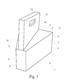
- Fig. 1 shows the transport box 1 having a food compartment 2 and a lid 3.
- the shape and mutual position of the rear wall 4, front wall 5 and the first and second side wall 6,7 of the food compartment 2 define the isosceles trapezoidal shape of its cross-section.
- the lid 3 has a first lid part 8 hingedly extending from the top edge 10 of the first side wall 6, and an opposite second lid part 9 hingedly extending from the top edge 11 of the second side wall 7.
- the first and second lid parts 8,9 will be described in more details in connection with fig. 2 .
- the lid parts 8,9 extend into and define an upright handle 12 (the upright part of the first lid part 8 is not visible in fig. 1 ) that a user can grab hold on and thereby conveniently carry the transport box.
- the second lid part 9 is shown with its swing flap 15 hingedly extending from an inside edge 16 of the second lid part 9 and in a position between the open and closed position of the swing flap 15.
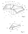
- Fig. 2 shows the transport box 1 in the transformed state, where the user via the opening 17 of the food compartment 2 has access to the food (not shown) located in the food compartment 2. This access is obtained as the first and second lid parts 8, 9 have been folded away from each other.
- top wall 18 and handle wall 20 of the first lid part 8, as well as the top wall 19 and handle wall 21 of the second lid part 9 are shown in the position where they are substantially horizontal, and thus able to function as a lap tray in combination with the food compartment 2.
- the food compartment 2 is intended to be positioned between and held in place by the thighs of the seated user with the rear wall 4 touching or at least located close to the crotch of the user, and where the first lid part 8 is extending over the left thigh of the user and the second lid part 9 is extending over the right thigh of the user.
- the first lid part 8 has a first top wall 18 hingedly extending from the top edge 10 of the first side wall 6, a first handle wall 20 extending from an inside edge 22 of the first top wall 18, an upright rim 24a extending from the free edges 26 of the first handle wall 20, an upright rim 24b hingedly extending from the front edge 28 of the first top wall 18, and a first swing flap 13 hingedly extending from an inside edge 14 of the first handle wall 20.
- the second lid part 9 has a correspondingly second top wall 19, hingedly extending from the top edge 11 of the second side wall 7, a second handle wall 21 extending from an inside edge 23 of the second top wall 19, an upright rim 25a extending from the free edges 27 of the second handle wall 21, an upright rim 25b hingedly extending from the front edge 29 of the second top wall 19, and a second swing flap 15 hingedly extending from an inside edge 16 (not visible) of the second handle wall 21.
- the upright rims 24a,25a of the handle walls 20,21 are locked at an interior angle of substantially 90° with respect to the handle walls 20,21, as is described in connection with fig. 6 .
- the upright rims 24b,25b of the top walls 18,19 are able to bend with respect to the top walls 18,19, but will assume an interior angle of substantially 90° (or close to 90°) with respect to the top walls 18,19 due to the build-in capability of the material to assume the intended three-dimensional form.
- the upright rims 24b,25b of the top walls 18,19 are not shown with their intended interior angle of 90° with respect to the top walls 18,19.
- the swing flaps 13,15 are shown in their closed position where they are parallel with the surface of the handle walls 20,21.
- Fig. 3 shows the insert 30 that can be placed at the bottom of the food compartment 2 via the opening 17 of the food compartment 2.
- the insert 30 has four support members 31a,31b,31c,31d (shown in the form of support walls) hingedly extending from its top wall 32, which has a circular opening 33 for holding a drinking cup.
- the edges of the top wall 32 are intended to touch the rear 4, front 5 and side walls 6,7 of the food compartment 2.
- each of the four support members 31a,31b,31c,31d in relation to the top wall 32 when the insert is placed in the food compartment is 90 degrees.
- Fig. 3 does not shown this angle for illustrative purposes. However, with this intended angle it is easily understood that the top wall 32 is raised from the bottom of the food compartment 2 and the insert 30 rests stable on the bottom of the food compartment 2.
- the height of the first and second support member 31b,31d increases towards the end of the top wall 32 where the circular opening 33 is located, and that the height of the rear support member 31a is higher than the height of the front support member 31c (more clearly shown in fig. 6 ).
- This variation in the height of the support members 31a,31b,31c,31d causes the top wall 32 to be tilted, so that food or other object located on the top wall 32 will tend to be moved away from the drinking cup in case e.g. the transport box 1 is moved around. Separation of the drinking cup from the food/objects is desirable in order to e.g. minimize any heat transfer between the typically cold drinking cup and any warm food.
- Fig. 4 shows an alternative embodiment of the insert 30' where the support members 31a',31b',31c',31d' has the same height.
- Fig. 5 shows the insert 30 seen in fig. 3 positioned inside the food compartment 2 of the transport box 1 shown in fig. 1 , where the support members 31a,31b,31c,31d are resting on the bottom of the food compartment 2.
- first and second blank 34,102 refers to the orientation of the first and second blank 34,102 when folded as shown in figures 1 and 2 .
- Fig. 6 shows the first blank 34 in its unfolded and flat state, where the first and second side wall 6,7 extend from the first and second fold line 35,36 of the rear wall 4, respectively.
- the front wall 5 extends from the front fold line 37 of the first side wall 7.
- the first and second bottom walls 38,39 extend from the bottom fold line 40,41 of the first and second side wall 6,7, respectively.
- the first connection means consists of three protruding flaps 42a,42b,42c extending from the interior edge 43 of the first bottom wall 38 and four protruding flaps 44a,44b,44c,44d extending from the interior edge 45 of the second bottom wall 39, where the flaps 42a,42b,42c,44a,44b,44c,44d are arranged so that when the two bottom walls 38,39 are brought together upon folding of the transport box 1 the flaps 42a,42b,42c,44a,44b,44c,44d are bend a bit upwards so that the flaps 42a,42b,42c of the first bottom wall 38 overlaps the second bottom wall 39, and vice versa. In this way the bottom walls 38,39 are able to engage each other in an interlocking manner.
- the first blank 34 has a rear bottom wall 46 extending from the bottom fold line 47 of the rear wall 4, and a front bottom wall 48 extending from the bottom fold line 49 of the front wall 5, where the rear and front bottom wall 46,48 in the folded state of the transport box 1 are positioned over the first and second bottom walls 38,39.
- This has the effect that there is no gap between the first/second bottom wall 38,39 and the rear/front wall 4,5 in the folded state, which inhibits e.g. liquid food from running down along the rear or front wall 4,5 and through any small gap between the rear/front wall and the bottom walls 38,39.
- the second connection means consists of the flap 50 extending from the fold line 51 of the front wall 5, the flap 52 extending from the fold line 53 on the front side of the second side wall 7, and the flap 54 hingedly extending from the fold line 55 of the second side wall 7.
- the flap 54 is made by performing a U-shaped cut 56 partly in the second side wall 7 and partly in the flap 52 as shown in fig. 6 .
- the flap 52 is bend into an angle parallel with the front wall 5 in its the folded state, the flap 50 is inserted into the slit created due to the cuts 56a,56b performed in the flap 52, and the flap 54 is afterwards bend into the slit created due to the cut 57 performed in the flap 50. In this way the front wall 5 and the second side wall 7 are connected to each other.
- a flap 58 is extending from the top fold line 59 of the front wall 5 and provided with two cut-out holes 60,61.
- the flap 58 is bend inwards into a position parallel with the front wall 5, which is provided with two cut-out holes 62,63 places opposite the holes 60,61 of the flap 58 as shown in fig. 6 .
- the first and second top wall 18,19 are extending from the top fold line 10 of the first side wall 6 and the top fold line 11 of the second side wall 7, respectively.
- Each of the first and second top wall 18,19 has a first flap 64,65 extending from the front fold line 28,29 of the first and second top wall 18,19, respectively, and a second flap 66,67 extending from the bottom fold line 68,69 of the first and second flap 64,65, respectively.
- the next folding step is to fold the first and second top walls 18,19 over the opening 17 of the food compartment 2 and inserting the left second flap 66 into the left holes 60,62 and the right second flap 67 into the right holes 61,63.
- the third connection means consists of the first and second flaps 64,65,66,67 and the cut-out holes 60,61,62,63.
- the first and second handle wall 20,21 are extending from the interior fold line 22,23 of the first and second top wall 18,19, respectively.
- Each of the handle walls 20,21 has a front flap 70,71 extending from the front fold line 72,73 of the handle wall 20,21, where each of the front flaps 70,71 has a tuck-in tab 74,75 extending from the top fold line 76,77 of the front flap 70,71.
- Each of the handle walls 20,21 also has a rear flap 78,79 extending from a rear fold line 80,81 of the handle wall 20,21, where each of the rear flaps 78,79 has a tuck-in tab 82,83 extending from a top fold line 84,85 of the rear flap 78,79.
- each of the handle walls 20,21 has a first top flap 86,87 extending from a top fold line 88,89 of the handle wall 20,21, where a second top flap 90,91 is extending from the top fold line 92,93 of each of the first top flaps 86,87.
- the upright rim 24a of the first handle wall 20 is made by folding the rear and front flaps 70,78 into a position perpendicular to the handle wall 20, and folding the tuck-in tabs 74,82 into a position parallel with the top fold line 88 of the first handle wall 20.
- the rear and front flaps 70,78 and the tuck-in tabs 74,82 are held in this position by firstly folding the first top flap 86 into a position perpendicular to the handle wall 20, secondly folding the second top flap 90 into a position parallel with the first flap 86, and thirdly inserting the small flaps 94,95 of the second top flap 90 into the correspondingly shaped cut-out holes 96,97 in the handle wall 20.
- the rear 78, front 70, first and second top flaps 86,90 are interlocked and form the upright rim 24a shown in fig. 2 and 5 .
- the upright rim 25a of the second handle wall 21 is, in the same way, made by folding the rear 79, front 71, first and second 87,91 flaps, folding the tuck-in tabs 75,83 and interlocking them using the small flaps 98,99 and the cut-out holes 100,101.
- the first handle wall 20 and its upright rim 24a is able to fit into the second handle wall 21 and its upright rim 25a when the transport box 1 is in its transport state.
- These lengths A,B and heights C,D are adapted so that the there is friction between the upright rims 24a,25a, where this friction holds the first and second handle walls 20,21 together, and thus forms the upright handle 12 shown in fig. 1 .
- This length/height difference constitutes the fourth connection means of the embodiment shown in fig. 6 .
- Fig. 7 shows the second blank 102 in its unfolded and flat state, where the top wall 32 has a circular opening 33, and each of the support walls 31a,31b,31c,31d is extending from a fold line 103,104,105,106 of the top wall 32.
Landscapes
- Engineering & Computer Science (AREA)
- Mechanical Engineering (AREA)
- Cartons (AREA)
Priority Applications (10)
| Application Number | Priority Date | Filing Date | Title |
|---|---|---|---|
| EP20130168738 EP2805647A1 (de) | 2013-05-22 | 2013-05-22 | Transportbox |
| RU2015154728A RU2015154728A (ru) | 2013-05-22 | 2014-05-12 | Транспортировочный короб |
| EP14725664.8A EP2999379B1 (de) | 2013-05-22 | 2014-05-12 | Transportbox |
| US14/892,564 US10292515B2 (en) | 2013-05-22 | 2014-05-12 | Transport box |
| DK14725664.8T DK2999379T3 (da) | 2013-05-22 | 2014-05-12 | Transportkasse |
| JP2016514326A JP2016524573A (ja) | 2013-05-22 | 2014-05-12 | トランスポートボックス |
| CN201480041521.XA CN105407766B (zh) | 2013-05-22 | 2014-05-12 | 运输盒 |
| CA2912976A CA2912976A1 (en) | 2013-05-22 | 2014-05-12 | A transport box |
| AU2014270638A AU2014270638B2 (en) | 2013-05-22 | 2014-05-12 | A transport box |
| PCT/EP2014/059635 WO2014187691A1 (en) | 2013-05-22 | 2014-05-12 | A transport box |
Applications Claiming Priority (1)
| Application Number | Priority Date | Filing Date | Title |
|---|---|---|---|
| EP20130168738 EP2805647A1 (de) | 2013-05-22 | 2013-05-22 | Transportbox |
Publications (1)
| Publication Number | Publication Date |
|---|---|
| EP2805647A1 true EP2805647A1 (de) | 2014-11-26 |
Family
ID=48446183
Family Applications (1)
| Application Number | Title | Priority Date | Filing Date |
|---|---|---|---|
| EP20130168738 Withdrawn EP2805647A1 (de) | 2013-05-22 | 2013-05-22 | Transportbox |
Country Status (1)
| Country | Link |
|---|---|
| EP (1) | EP2805647A1 (de) |
Citations (5)
| Publication number | Priority date | Publication date | Assignee | Title |
|---|---|---|---|---|
| US5127339A (en) | 1991-08-16 | 1992-07-07 | Hood Jr John J | Foldable lap tray |
| US5425445A (en) | 1989-08-01 | 1995-06-20 | United States Surgical Corporation | Retainer for a combined surgical suture-needle device |
| GB2436791A (en) * | 2006-04-05 | 2007-10-10 | John Frederick Barnes | Box blank and connected cloth for use as picnic hamper and mat |
| DE202009011049U1 (de) * | 2009-09-24 | 2009-12-31 | Cofresco Frischhalteprodukte Gmbh & Co. Kg | Behälter |
| US20130034314A1 (en) * | 2011-02-18 | 2013-02-07 | Peacock C Glen | Convertible fast food package |
-
2013
- 2013-05-22 EP EP20130168738 patent/EP2805647A1/de not_active Withdrawn
Patent Citations (5)
| Publication number | Priority date | Publication date | Assignee | Title |
|---|---|---|---|---|
| US5425445A (en) | 1989-08-01 | 1995-06-20 | United States Surgical Corporation | Retainer for a combined surgical suture-needle device |
| US5127339A (en) | 1991-08-16 | 1992-07-07 | Hood Jr John J | Foldable lap tray |
| GB2436791A (en) * | 2006-04-05 | 2007-10-10 | John Frederick Barnes | Box blank and connected cloth for use as picnic hamper and mat |
| DE202009011049U1 (de) * | 2009-09-24 | 2009-12-31 | Cofresco Frischhalteprodukte Gmbh & Co. Kg | Behälter |
| US20130034314A1 (en) * | 2011-02-18 | 2013-02-07 | Peacock C Glen | Convertible fast food package |
Similar Documents
| Publication | Publication Date | Title |
|---|---|---|
| US10292515B2 (en) | Transport box | |
| EP1303441B1 (de) | Träger für getränke und nahrungsmittel | |
| US4705173A (en) | Carryout tray with diverse apertures | |
| US8186530B2 (en) | Food tray | |
| US7232055B1 (en) | Folding serving tray | |
| AU2001273027A1 (en) | Beverage and food carrier | |
| US4562926A (en) | Compartmented food placemat | |
| US4489879A (en) | Multi-compartmented food serving tray and blank therefor | |
| US20090321503A1 (en) | Foldable Container for Picnics | |
| US20060214075A1 (en) | Beverage holder adapters for non-cylindrical, multi-sided food containers | |
| US2679971A (en) | Automatic serving tray | |
| US20120228319A1 (en) | Portable Carrier | |
| KR101010242B1 (ko) | 용기 | |
| JPH09220153A (ja) | タックエンドカートン型ハンドトレー | |
| EP2246268B1 (de) | An einer Behälterseite hängender Träger | |
| JPS607295Y2 (ja) | 食事用外装箱 | |
| US20070012754A1 (en) | Slanted Clamshell Container with Sauce Holder | |
| US20050263576A1 (en) | Fast food container with separable bottom trough | |
| US20150216345A1 (en) | Food tray having improved lap placement characteristics | |
| GB2297313A (en) | Packaging trays | |
| JPS607296Y2 (ja) | 食事用外装箱 | |
| WO2017064738A1 (en) | Food box convertible into a two-level tray | |
| ITPD20100156A1 (it) | Contenitore per alimenti in particolare per cibi da asporto | |
| HK1148509B (en) | Carrier formed of foldable sheet material |
Legal Events
| Date | Code | Title | Description |
|---|---|---|---|
| PUAI | Public reference made under article 153(3) epc to a published international application that has entered the european phase |
Free format text: ORIGINAL CODE: 0009012 |
|
| 17P | Request for examination filed |
Effective date: 20130522 |
|
| AK | Designated contracting states |
Kind code of ref document: A1 Designated state(s): AL AT BE BG CH CY CZ DE DK EE ES FI FR GB GR HR HU IE IS IT LI LT LU LV MC MK MT NL NO PL PT RO RS SE SI SK SM TR |
|
| AX | Request for extension of the european patent |
Extension state: BA ME |
|
| RAP1 | Party data changed (applicant data changed or rights of an application transferred) |
Owner name: TABLEBOX APS |
|
| RIN1 | Information on inventor provided before grant (corrected) |
Inventor name: TABLEBOX APS |
|
| STAA | Information on the status of an ep patent application or granted ep patent |
Free format text: STATUS: THE APPLICATION IS DEEMED TO BE WITHDRAWN |
|
| 18D | Application deemed to be withdrawn |
Effective date: 20150527 |