EP2805307B1 - Procédé et appareil de compression d'informations de texture de modèles tridimensionnels (3d) - Google Patents
Procédé et appareil de compression d'informations de texture de modèles tridimensionnels (3d) Download PDFInfo
- Publication number
- EP2805307B1 EP2805307B1 EP12866302.8A EP12866302A EP2805307B1 EP 2805307 B1 EP2805307 B1 EP 2805307B1 EP 12866302 A EP12866302 A EP 12866302A EP 2805307 B1 EP2805307 B1 EP 2805307B1
- Authority
- EP
- European Patent Office
- Prior art keywords
- texture
- instance
- pattern
- mode
- bitstream
- Prior art date
- Legal status (The legal status is an assumption and is not a legal conclusion. Google has not performed a legal analysis and makes no representation as to the accuracy of the status listed.)
- Active
Links
- 238000000034 method Methods 0.000 title claims description 40
- 230000003252 repetitive effect Effects 0.000 claims description 20
- 230000009466 transformation Effects 0.000 claims description 16
- 239000011159 matrix material Substances 0.000 claims description 8
- 238000009877 rendering Methods 0.000 claims 5
- 230000001131 transforming effect Effects 0.000 claims 1
- 230000000875 corresponding effect Effects 0.000 description 25
- 230000005540 biological transmission Effects 0.000 description 11
- 230000006835 compression Effects 0.000 description 11
- 238000007906 compression Methods 0.000 description 11
- 238000010586 diagram Methods 0.000 description 10
- 238000012545 processing Methods 0.000 description 10
- 230000008569 process Effects 0.000 description 6
- 230000008901 benefit Effects 0.000 description 3
- 238000013507 mapping Methods 0.000 description 3
- 238000007781 pre-processing Methods 0.000 description 3
- 238000013519 translation Methods 0.000 description 3
- 239000000969 carrier Substances 0.000 description 2
- 239000003086 colorant Substances 0.000 description 2
- 238000004891 communication Methods 0.000 description 2
- 238000012937 correction Methods 0.000 description 2
- 230000002596 correlated effect Effects 0.000 description 2
- 210000000887 face Anatomy 0.000 description 2
- 230000006870 function Effects 0.000 description 2
- 238000013139 quantization Methods 0.000 description 2
- 229920001690 polydopamine Polymers 0.000 description 1
- 230000008707 rearrangement Effects 0.000 description 1
- 238000001228 spectrum Methods 0.000 description 1
- 238000000844 transformation Methods 0.000 description 1
- 238000012800 visualization Methods 0.000 description 1
Images


Classifications
-
- H—ELECTRICITY
- H04—ELECTRIC COMMUNICATION TECHNIQUE
- H04N—PICTORIAL COMMUNICATION, e.g. TELEVISION
- H04N13/00—Stereoscopic video systems; Multi-view video systems; Details thereof
- H04N13/10—Processing, recording or transmission of stereoscopic or multi-view image signals
- H04N13/106—Processing image signals
- H04N13/161—Encoding, multiplexing or demultiplexing different image signal components
-
- G—PHYSICS
- G06—COMPUTING; CALCULATING OR COUNTING
- G06T—IMAGE DATA PROCESSING OR GENERATION, IN GENERAL
- G06T15/00—3D [Three Dimensional] image rendering
- G06T15/04—Texture mapping
-
- G—PHYSICS
- G06—COMPUTING; CALCULATING OR COUNTING
- G06T—IMAGE DATA PROCESSING OR GENERATION, IN GENERAL
- G06T9/00—Image coding
- G06T9/001—Model-based coding, e.g. wire frame
-
- H—ELECTRICITY
- H04—ELECTRIC COMMUNICATION TECHNIQUE
- H04N—PICTORIAL COMMUNICATION, e.g. TELEVISION
- H04N19/00—Methods or arrangements for coding, decoding, compressing or decompressing digital video signals
- H04N19/20—Methods or arrangements for coding, decoding, compressing or decompressing digital video signals using video object coding
- H04N19/23—Methods or arrangements for coding, decoding, compressing or decompressing digital video signals using video object coding with coding of regions that are present throughout a whole video segment, e.g. sprites, background or mosaic
Definitions
- This invention relates to a method and apparatus for generating a bitstream representative of a 3D model, and a method and apparatus for decoding the same.
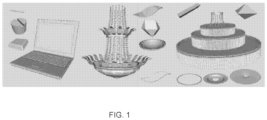
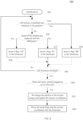
- 3D models consist of a large number of connected components. These multi-component 3D models usually contain many repetitive structures in various transformations, as shown in FIG. 1 .
- Compression algorithms for multi-component 3D models that take advantage of repetitive structures in the input models are known. Repetitive structures of a 3D model are discovered in various positions, orientations, and scaling factors. The 3D model is then organized into "pattern-instance" representation.
- a pattern is used to denote a representative geometry of the corresponding repetitive structure.
- Components belonging to a repetitive structure are denoted as instances of the corresponding pattern and may be represented by a pattern ID and transformation information, for example, reflection, translation, rotation and possible scaling with respect to the pattern.
- the instance transformation information may be organized into, for example, reflection part, translation part, rotation part, and possible scaling part.
- the repetitive structures may be organized into patterns and instances, wherein an instance is represented as a transformation of a corresponding pattern, for example, using a pattern ID of the corresponding pattern and a transformation matrix which contains information on translation, rotation, and scaling.
- an instance When an instance is represented by a pattern ID and a transformation matrix, the pattern ID and the transformation matrix are to be compressed when compressing the instance. Consequently, an instance may be reconstructed through the pattern ID and the decoded transformation matrix, that is, an instance may be reconstructed as transformation (from the decoded transformation matrix) of a decoded pattern indexed by the pattern ID.
- one or more texture images may be transmitted together with the geometry.
- Each face of the 3D model corresponds to a certain area of the texture image(s).
- the corresponding coordinates in the texture image(s) for each vertex is encoded to represent the mapping relationship.
- the present principles provide a method and apparatus for efficiently compressing texture information of 3D models by utilizing the redundancy between repetitive textures.
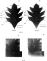
- FIG. 2A illustrates an exemplary pattern 201 and an exemplary instance 202.
- Each vertex or face is indicated by an index.
- face 240 in the pattern is indicated by an index T6, and its three vertices are indicated by indices V13, V12, and V14.
- a corresponding face 245 in the instance is indicated by an index T20, and its three vertices are indicated by indices V12, V8, and V3.
- a face or vertex in the pattern corresponds to a face or vertex in the instance, or vice versa, when they substantially overlap each other when the pattern and instance are aligned.
- the indices for corresponding faces or vertices are different for the pattern and instance.
- FIG. 2B illustrates exemplary texture images 203 and 204 for pattern 201 and instance 202 respectively.
- a 3D model can be represented by a vertex table (V0, V1, V2, ...) consisting of all vertex coordinates and a triangle table (T0, T1, T2, ...) consisting of all triangles' vertex indices in the vertex table.
- each vertex and triangle could have one or more properties, such as normal, color, and texture coordinate.
- Those vertex properties and triangle properties may be attached to vertices and triangles in the corresponding table or may be stored in additional vertex/triangle property tables following the same vertex/triangle order in the vertex/triangle table.
- TABLE 1 illustrates an exemplary 3D mesh file that contains definitions for vertices, texture coordinates, normals, and faces.
- texture coordinate indices can be used to specify texture coordinates when defining a face.
- the format is vertex index/texture coordinate index/normal index.
- each face has a three-tuple of texture coordinate indices. All these tuples form a list.
- Correspondence between a pattern and instance may be based on one-to-one vertex correspondence, which can be built by a nearest neighbor searching algorithm such as KD-tree searching.
- a nearest neighbor searching algorithm such as KD-tree searching.
- one instance should also have one-to-one triangle correspondence with the corresponding pattern, which is consistent with the one-to-one vertex correspondence. All triangles of one instance could have opposite normals with their corresponding pattern after the pattern has been aligned with the instance component, which means the instance and pattern are flipped with respect to each other. As shown in FIG. 3B , triangle T pi corresponds to T ii , however, T pi and T ii have different orientations (i.e., opposite normals).
- a pattern and instances correspond to repetitive structures, it may be possible to re-use the geometry of pattern to encode geometry information of instances.
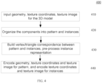
- FIG. 4 shows an exemplary method 400 for encoding a 3D model.
- the 3D model data e.g., geometry, texture coordinate, and texture image
- the 3D model data is input at step 410.
- components within the 3D model are organized into patterns and instances.
- it builds vertex and triangle correspondences between patterns and instances and pre-processes the representation of instance components.
- the 3D model is encoded. Specifically, the properties of patterns may be re-used for encoding the instances.
- TABLE 2 shows the correspondence between vertices and triangles between pattern 201 and instance 202, both shown in FIG. 2A . That is, even if a pattern and instance correspond to similar structure, their representations in 3D mesh files are different.
- a new texture image can be generated by re-arranging the corresponding triangles in the instance's initial texture image.
- the pattern's texture coordinates will be used. That is, the mapping is derived from the transformation from the instance's texture coordinates to the pattern's texture coordinates. Consequently, the instance may be able to use the texture related data from the pattern except the texture image.
- texture coordinates and indices without generating a new texture image.
- the texture coordinates may first be re-ordered according to the vertex and triangle orders of the pattern. Once repetitive structure based on purely geometrical information has been identified, this information could be used to process the texture data.
- the vertex correspondence between pattern and instance may be identified, for example, by nearest neighbor search. Once we know the vertex correspondence, the triangle correspondence may be obtained. Then, we run this procedure for all the vertices and triangles and obtain the correspondence table as shown in TABLE 2. Note that the vertex correspondence and the triangle correspondence need to be one-to-one. For example, vertex 210 (vertex index V13) in pattern 201 corresponds to vertex 215 (vertex index V12) in instance 202, and face/triangle 240 (face index T6) in the pattern corresponds to face/triangle 245 (face index T20) in the instance.
- face T6 in the pattern is described as T6: V12/TEX_12 V13/TEX_13 V14/TEX_14
- face T20 in the instance is described as T20: V3/TEX_3 V8/TEX_8 V12/TEX_12. Note that the vertex index/ texture coordinate index is used to represent the face here (i.e., normal index is not shown).
- FIGs. 5B and 5C illustrates exemplary texture coordinates before and after adjusting, respectively.
- the face definitions for the instance are based on the vertex indices and triangles indices of the instance.
- the instance uses corresponding pattern's vertex indices and triangles' order. Consequently, T20: V3/TEX_3 V8/TEX_8 V12/TEX_12 will be changed into T6: V12/TEX_8 V13/TEX_12 V14/TEX_3.
- the texture coordinates for face 245 in the instance becomes from TEX_3, TEX_8, TEX_12 (as illustrated in FIG. 5B ) to TEX_8, TEX_12, TEX_3 (as illustrated in FIG. 5C ).
- other properties, such as colors and normals are considered, they also need to be re-ordered a similar fashion.
- the property (e.g., texture, normal) of the pattern can be used to efficiently encode the instance property.
- the present principles examine the similarity between textures of a pattern and an instance. If the texture coordinates of the pattern and the instance are identical, that is, the instance uses the same texture as the pattern, no texture is to be encoded for the instance. Rather, a flag is written into the bitstream to inform the decoder to copy the texture of the pattern when reconstructing the instance. If the texture coordinates of the pattern and the instances are different, contents of corresponding areas in texture images are compared between the pattern and the instance. If the contents are different, the texture coordinate of the instance is encoded. If the contents are identical or almost identical, the region corresponding to the instance is removed from the texture images, and the decoder copies the texture of the pattern when reconstructing the instance.
- a difference image between the pattern and the instance is generated, the region corresponding to the instance in the texture images is replaced with the difference image, and a flag is written into the bitstream to inform the decoder to generate the texture for the instance by adding the difference image to the instance texture. Consequently, the texture of an instance is predictively encoded from the texture of the pattern to exploit the redundancy of the texture image.
- texture property In addition to texture property, other properties, for example, but not limited to, normals and colors, of an instance may be identical or similar to the corresponding pattern properties. Similar to texture, these properties of the instance can be predicted from the properties of the pattern, and the prediction errors instead of the properties are encoded. In the following, we use texture as an example to illustrate how we can use the similarity between a pattern and instance when encoding the instance.
- FIGs. 6A and 6B show portions of a texture image for a 3D model that corresponds to an eye of a bunny.
- the eye in FIG. 6A is quite similar to the eye in FIG. 6B and it is possible to use one eye to represent the other.
- these two eyes belong to two components A and B, wherein component B is an instance of the pattern A, and the problem is to decide whether texture of B can be represented by texture of A.
- a patch is a region in the texture image that corresponds to a set of adjacent triangles on the 3D model. It may contain one or more triangles of the component. Exactly how many triangles are in a patch may depend on the input 3D model.
- FIG. 7 illustrates an exemplary method 700 for determining the similarity of a texture patch for an instance with a corresponding texture patch for a pattern.
- Method 700 starts with an initialization step 705.
- the initialization step may divide texture images into a number of patches, each patch corresponding to a part of one or more components, whose IDs may be recorded.
- both "remove" and "replace” flags are set to 0.
- step 710 it checks if the patch represents texture of a part of a pattern or unique component. If yes, the control is passed to an end step 799. Otherwise, method 700 proceeds to examine the texture patch and it checks every instance whose texture is (partly) represented by the patch.
- step 720 it compares the texture patch with the corresponding patch used by its pattern using a certain matching criteria, for example, mean square error (MSE).
- MSE mean square error
- step 730 it checks the correlation between the instance texture and the pattern texture. If the textures are highly correlated (e.g., MSE ⁇ threshold0 ) , the instance texture is considered as identical or almost identical to the pattern texture, and it can be represented by the pattern texture. A "remove" flag is then set to 1 (i.e., the patch is tagged as to be removed) and the texture coordinates may be updated, for example, by translating the instance's texture coordinates according to the relative position between the instance texture and the pattern texture, at step 750.
- MSE mean square error
- the texture is moderately correlated (e.g., threshold0 ⁇ MSE ⁇ threshold1 )
- step 775 it checks whether there are more instances corresponding to the texture patch. If yes, the control is returned to step 720. Otherwise, when all instances using the patch are finished, it checks whether a "replace" flag is 1 at step 780. If yes, the patch is replaced with the difference between the pattern texture and the instance texture (785). Otherwise, the control is passed to end step 799.
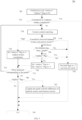
- step 840 If all texture coordinates of an instance are identical to the pattern (810), it sets the mode flag to '00' (mode 1) at step 840, indicating that the pattern and the instance share textures. If some of the patches are replaced with difference (820), it sets the mode flag to '10' (mode 3) at step 830. Otherwise, it sets the mode flag to '01' (modes2 and 4) at step 835. It checks whether all instances are processed at step 850. At step 860, it checks whether any patch has a "remove" flag set to 1. If yes, patches are re-arranged in the texture image and texture coordinates of the entire 3D model are updated (870). The mode flag is signaled in the bitstream, and the texture coordinates are transmitted if the mode flag is not '00' (880). Note that different bit strings can be used to represent the mode.
- FIG. 9 illustrates an exemplary method 900 for decoding the texture of the instances. For each instance, it decodes the mode flag at step 910. Then method 900 proceeds according to the mode flag (920).
- the mode flag is '00', it uses the texture of the pattern for the whole instance (940).
- the mode flag is '01', it decodes the texture coordinates at step 930 and finds the texture patch according to the decoded texture coordinates at step 935.
- the mode flag is '10', it decodes the texture coordinates at step 950 and it copies the texture image according to texture coordinates at step 955. Then it updates the instance texture by adding the texture image from the pattern at step 960. Method 900 ends at step 999.
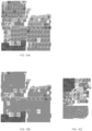
- FIG. 10A is an exemplary texture image used as the input
- FIGs. 10B and 10C are exemplary texture images after processing, for example, using methods 700 and 800.
- patches tagged to be removed is replaced with gray blocks.
- patches tagged to be removed are physically removed from the texture image.
- FIG. 10B there are many gray regions in the texture image which correspond to removed texture patches.
- FIG. 10C the patches are re-arranged, that is, the gray patches are removed, and remaining texture patches are put together, resulting in a much smaller texture image. In both cases, there is less information to be compressed, and thus, may improve the compression efficiency of the texture image.
- compr_elem_insta_texture_header is a mode flag. Its specific meaning is shown in TABLE 4. Note that the "share” mode corresponds to mode '00' in FIG. 9 , the "no_pred” mode corresponds to mode '01' in FIG. 9 , and the "texture_residual” mode corresponds to mode '10' in FIG. 9 . TABLE 4 elem_insta_t exCoord_co mpr_mode Mode Meaning 0 share The instance shares texture with the corresponding pattern. 1 ISO reserved 2 no_pred The instance has its specific texture coordinate data which is reconstructed by de-quantization and entropy decoding, without prediction.
- the texture of the reconstructed instance is to be obtained by decoding the texture coordinates from the bitstream and mapping the texture image portion indicated by the decoded texture coordinates.
- 3 texture_residual The instance has its specific texture coordinate data which is reconstructed by de-quantization and entropy decoding, without prediction.
- the texture of the reconstructed instance is to be reconstructed by compensated mode using the texture of the corresponding pattern and the texture indicated by the reconstructed texture coordinates.
- compr_elem_insta_texcoord_data includes all the texture coordinates of vertices if the mode is "no_pred” or “texture_residual.” It shall be null if the mode is "share.”
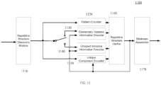
- FIG.11 depicts a block diagram of an exemplary 3D model encoder 1100.
- methods 700 and 800 may be used in encoder 1100.
- the input of apparatus 1100 may include a 3D model, quality parameter for encoding the 3D mode and other metadata.
- the 3D model first goes through the repetitive structure discovery module 1110, which outputs the 3D model in terms of patterns, instances and unique components.
- a pattern encoder1120 is employed to compress the patterns and a unique component encoded 150 is employed to encode the unique components.
- the instance component information is encoded based on a user-selected mode. If instance information group mode is selected, the instance information is encoded using grouped instance information encoder1140; otherwise, it is encoded using an elementary instance information encoder1130.
- the encoded components are further verified in the repetitive structure verifier 1160. If an encoded component does not meet its quality requirement, it will be encoded using unique component encoder 1150. Bitstreams for patterns, instances, and unique components are assembled at bitstream assembler 1170
- FIG. 12 depicts a block diagram of an exemplary 3D model decoder 1200.
- method 900 may be used in decoder 1200.
- the input of apparatus 1200 may include a bitstream of a 3D model, for example, a bitstream generated by methods 700 and 800.
- the information related to patterns in the compressed bitstream is decoded by pattern decoder1220.
- Information related to unique components is decoded by unique component decoder1250.
- the decoding of the instance information also depends on the user-selected mode.
- instance information group mode the instance information is decoded using a grouped instance information decoder1240; otherwise, it is decoded using an elementary instance information decoder1230.
- the decoded patterns, instance information and unique components are reconstructed to generate an output decoded 3D model at model reconstruction module 1260.
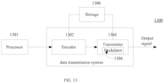
- the data transmission system or apparatus 1300 may be, for example, a head-end or transmission system for transmitting a signal using any of a variety of media, such as, for example, satellite, cable, telephone-line, or terrestrial broadcast.
- the data transmission system or apparatus 1300 also, or alternatively, may be used, for example, to provide a signal for storage.
- the transmission may be provided over the Internet or some other network.
- the data transmission system or apparatus 1300 is capable of generating and delivering, for example, video content and other content such as, for example, 3D models.
- the data transmission system or apparatus 1300 receives processed data and other information from a processor 1301.
- the processor 1301 processes geometry data of 3D models to generate "pattern-instance" representation.
- the processor 1301 may also provide metadata to 1300 indicating, for example, the pattern ID and the transformation.
- the data transmission system or apparatus 1300 includes an encoder 1302 and a transmitter 1304 capable of transmitting the encoded signal.
- the encoder 1302 receives data information from the processor 1301.
- the encoder 1302 generates an encoded signal(s).
- the encoder 1302 may include sub-modules, including for example an assembly unit for receiving and assembling various pieces of information into a structured format for storage or transmission.
- the various pieces of information may include, for example, coded or uncoded video, and coded or uncoded elements such as, for example, substream length indicator, and syntax elements.
- the encoder 1302 includes the processor 1301 and therefore performs the operations of the processor 1301.
- the transmitter 1304 receives the encoded signal(s) from the encoder 1302 and transmits the encoded signal(s) in one or more output signals.
- the transmitter 1304 may be, for example, adapted to transmit a program signal having one or more bitstreams representing encoded pictures and/or information related thereto.
- Typical transmitters perform functions such as, for example, one or more of providing error-correction coding, interleaving the data in the signal, randomizing the energy in the signal, and modulating the signal onto one or more carriers using a modulator 1306.
- the transmitter 1304 may include, or interface with, an antenna (not shown). Further, implementations of the transmitter 1304 may be limited to the modulator 1306.
- the data transmission system or apparatus 1300 is also communicatively coupled to a storage unit 1308.
- the storage unit 1308 is coupled to the encoder 1302, and stores an encoded bitstream from the encoder 1302.
- the storage unit 1308 is coupled to the transmitter 1304, and stores a bitstream from the transmitter 1304.
- the bitstream from the transmitter 1304 may include, for example, one or more encoded bitstreams that have been further processed by the transmitter 1304.
- the storage unit 1308 is, in different implementations, one or more of a standard DVD, a Blu-Ray disc, a hard drive, or some other storage device.
- the data receiving system or apparatus 1400 may be configured to receive signals over a variety of media, such as, for example, storage device, satellite, cable, telephone-line, or terrestrial broadcast.
- the signals may be received over the Internet or some other network.
- the data receiving system or apparatus 1400 may be, for example, a cell-phone, a computer, a set-top box, a television, or other device that receives encoded video and provides, for example, decoded video signal for display (display to a user, for example), for processing, or for storage.
- the data receiving system or apparatus 1400 may provide its output to, for example, a screen of a television, a computer monitor, a computer (for storage, processing, or display), or some other storage, processing, or display device.
- the data receiving system or apparatus 1400 is capable of receiving and processing data information, and the data information may include, for example, 3D models.
- the data receiving system or apparatus 1400 includes a receiver 1402 for receiving an encoded signal, such as, for example, the signals described in the implementations of this application.
- the receiver 1402 may receive, for example, a signal providing one or more of the 3D models and/or texture images, or a signal output from the data transmission system 1200 of FIG. 12 .
- the receiver 1402 may be, for example, adapted to receive a program signal having a plurality of bitstreams representing encoded pictures. Typical receivers perform functions such as, for example, one or more of receiving a modulated and encoded data signal, demodulating the data signal from one or more carriers using a demodulator 1404, de-randomizing the energy in the signal, de-interleaving the data in the signal, and error-correction decoding the signal.
- the receiver 1402 may include, or interface with, an antenna (not shown). Implementations of the receiver 1402 may be limited to the demodulator 1404.
- the data receiving system or apparatus 1400 includes a decoder 1406.
- the receiver 1402 provides a received signal to the decoder 1406.
- the signal provided to the decoder 1406 by the receiver 1402 may include one or more encoded bitstreams.
- the decoder 1406 outputs a decoded signal, such as, for example, decoded video signals including video information.
- the decoder 1406 may be, for example, decoder 1200 described in FIG. 12 .
- the data receiving system or apparatus 1400 is also communicatively coupled to a storage unit 1407.
- the storage unit 1407 is coupled to the receiver 1402, and the receiver 1402 accesses a bitstream from the storage unit 1407.
- the storage unit 1407 is coupled to the decoder 1406, and the decoder 1406 accesses a bitstream from the storage unit 1407.
- the bitstream accessed from the storage unit 1407 includes, in different implementations, one or more encoded bitstreams.
- the storage unit 1407 is, in different implementations, one or more of a standard DVD, a Blu-Ray disc, a hard drive, or some other storage device.
- the output data from the decoder 1406 is provided, in one implementation, to a processor 1408.
- the processor 1408 is, in one implementation, a processor configured for performing 3D model reconstruction.
- the decoder 1406 includes the processor 1408 and therefore performs the operations of the processor 1408.
- the processor 1408 is part of a downstream device such as, for example, a set-top box or a television.
- 3D model encoding and decoding may allow a variety of applications, such as, for example, video gaming, virtual reality, and scientific visualization.
- applications such as, for example, video gaming, virtual reality, and scientific visualization.
- variations of these implementations and additional applications are contemplated and within our disclosure, and features and aspects of described implementations may be adapted for other implementations.
- the implementations described herein may be implemented in, for example, a method or a process, an apparatus, a software program, a data stream, or a signal. Even if only discussed in the context of a single form of implementation (for example, discussed only as a method), the implementation of features discussed may also be implemented in other forms (for example, an apparatus or program).
- An apparatus may be implemented in, for example, appropriate hardware, software, and firmware.
- the methods may be implemented in, for example, an apparatus such as, for example, a processor, which refers to processing devices in general, including, for example, a computer, a microprocessor, an integrated circuit, or a programmable logic device. Processors also include communication devices, such as, for example, computers, cell phones, portable/personal digital assistants ("PDAs”), and other devices that facilitate communication of information between end-users.
- PDAs portable/personal digital assistants
- the appearances of the phrase “in one embodiment” or “in an embodiment” or “in one implementation” or “in an implementation”, as well any other variations, appearing in various places throughout the specification are not necessarily all referring to the same embodiment.
- Determining the information may include one or more of, for example, estimating the information, calculating the information, predicting the information, or retrieving the information from memory.
- Accessing the information may include one or more of, for example, receiving the information, retrieving the information (for example, from memory), storing the information, processing the information, transmitting the information, moving the information, copying the information, erasing the information, calculating the information, determining the information, predicting the information, or estimating the information.
- Receiving is, as with “accessing”, intended to be a broad term.
- Receiving the information may include one or more of, for example, accessing the information, or retrieving the information (for example, from memory).
- “receiving” is typically involved, in one way or another, during operations such as, for example, storing the information, processing the information, transmitting the information, moving the information, copying the information, erasing the information, calculating the information, determining the information, predicting the information, or estimating the information.
- implementations may produce a variety of signals formatted to carry information that may be, for example, stored or transmitted.
- the information may include, for example, instructions for performing a method, or data produced by one of the described implementations.
- a signal may be formatted to carry the bitstream of a described embodiment.
- Such a signal may be formatted, for example, as an electromagnetic wave (for example, using a radio frequency portion of spectrum) or as a baseband signal.
- the formatting may include, for example, encoding a data stream and modulating a carrier with the encoded data stream.
- the information that the signal carries may be, for example, analog or digital information.
- the signal may be transmitted over a variety of different wired or wireless links, as is known.
- the signal may be stored on a processor-readable medium.
Landscapes
- Engineering & Computer Science (AREA)
- Multimedia (AREA)
- Physics & Mathematics (AREA)
- General Physics & Mathematics (AREA)
- Theoretical Computer Science (AREA)
- Signal Processing (AREA)
- Computer Graphics (AREA)
- Image Generation (AREA)
- Compression Or Coding Systems Of Tv Signals (AREA)
- Processing Or Creating Images (AREA)
Claims (11)
- Procédé comprenant les étapes suivantes :décodage (910) à partir d'un flux binaire :- de motifs (201), chaque motif étant un maillage 3D, dans lequel chaque motif est identifié par un indice et associé à une première image de texture (203) et à des coordonnées de texture attachées aux sommets ;- d'instances (202), une instance comprenant une référence à un indice d'un modèle, une matrice de transformation et une information de mode indiquant :• un premier mode indiquant que le flux binaire ne contient ni les coordonnées de texture ni l'image de texture de l'instance ;• un deuxième mode indiquant que les coordonnées de texture de l'instance sont codées dans le flux binaire, mais que l'image de texture de l'instance est ignorée ;• un troisième mode indiquant qu'une image de différence et les coordonnées de texture de l'instance sont codées dans le flux binaire ; ou• un quatrième mode indiquant qu'une deuxième image de texture et les coordonnées de texture sont codées dans le flux binaire ; etpour une instance, le rendu de l'instance par la transformation du maillage 3D de son modèle avec la matrice de transformation, et :si l'information de mode indique le premier mode, le rendu de l'instance à l'aide des coordonnées de texture et de la première image de texture du motif référencé et de la première image de texture ;si l'information de mode indique le deuxième mode, le décodage des coordonnées de texture de l'instance à partir du flux binaire et le rendu de l'instance à l'aide de la première image de texture ;si l'information de mode indique le troisième mode, le décodage des coordonnées de texture de l'instance et de l'image de différence à partir du flux binaire, la génération d'une troisième image de texture par l'ajout de l'image de différence à la première image de texture et le rendu de l'instance à l'aide de la troisième image de texture ; etsi l'information de mode indique le quatrième mode, le décodage des coordonnées de texture de l'instance et de la deuxième image de texture à partir du flux binaire et le rendu de l'instance à l'aide de la deuxième image de texture.
- Procédé de génération d'un flux binaire représentant un modèle de maillage triangulaire 3D comprenant des structures répétitives organisées en motifs et en instances,- un motif étant un maillage 3D (201) dans lequel chaque motif est identifié par un indice et associé à une première image de texture (203) et à des coordonnées de texture attachées aux sommets ; et- une instance (202) comprenant une référence à un indice d'un motif correspondant, une matrice de transformation et étant associée à une deuxième image de texture et à des deuxièmes coordonnées de texture ;ledit procédé comprenant les étapes suivantes :codage des motifs dans le flux binaire ;pour chaque instance, codage dans le flux binaire de l'instance et d'une information de mode indiquant• un premier mode si les coordonnées de texture de l'instance sont les coordonnées de texture du motif ; ou si les coordonnées de texture de l'instance sont différentes des coordonnées de texture du motif ;• un deuxième mode si l'image de texture de l'instance est la première image de texture du motif ;• un troisième mode si l'image de texture de l'instance est différente, mais similaire à la première image de texture ;• un quatrième mode autrement ; etsi l'information de mode indique le deuxième mode, codage des deuxièmes coordonnées de texture dans le flux binaire ;si l'information de mode indique le troisième mode, codage des deuxièmes coordonnées de texture et d'une image de différence dans le flux binaire, l'image de différence étant la première image de texture moins la deuxième image de texture ; etsi l'information de mode indique le quatrième mode, codage des coordonnées de texture de l'instance et de la deuxième image de texture dans le flux binaire.
- Procédé selon la revendication 2, comprenant en outre les étapes consistant à :déterminer (730) une corrélation entre un patch de texture de l'instance dans la deuxième image de texture et un patch de texture correspondant du motif dans la première image de texture ; etdéterminer si le patch de texture de l'instance doit être codé à l'aide du patch de texture correspondant du motif,dans lequel un patch de texture est une région d'une image de texture.
- Procédé selon la revendication 3, dans lequel le patch de texture de l'instance est supprimé de la deuxième image de texture si le patch de texture de l'instance est déterminé comme étant identique au patch de texture correspondant du motif.
- Procédé selon la revendication 3, dans lequel les pixels du patch de texture de l'instance sont définis sur une couleur prédéfinie si le patch de texture de l'instance est déterminé comme étant identique au patch de texture correspondant du modèle.
- Procédé selon la revendication 3, dans lequel le patch de texture de l'instance est une région d'une image de texture qui correspond aux coordonnées de texture d'un ensemble de triangles adjacents sur le modèle 3D.
- Appareil comprenant des moyens pour générer un flux binaire selon les revendications 2 à 6.
- Support de stockage lisible sur ordinateur sur lequel sont stockées des instructions pour générer un flux binaire selon les revendications 2 à 6.
- Support de stockage lisible sur ordinateur sur lequel est stocké un flux binaire généré selon les revendications 2 à 6.
- Appareil comprenant des moyens pour décoder un flux binaire selon la revendication 1.
- Support de stockage lisible sur ordinateur sur lequel sont stockées des instructions pour décoder un flux binaire selon la revendication 1.
Applications Claiming Priority (3)
| Application Number | Priority Date | Filing Date | Title |
|---|---|---|---|
| CN2012070703 | 2012-01-21 | ||
| CN2012074356 | 2012-04-19 | ||
| PCT/CN2012/087935 WO2013107273A1 (fr) | 2012-01-21 | 2012-12-29 | Procédé et appareil de compression d'informations de texture de modèles tridimensionnels (3d) |
Publications (3)
| Publication Number | Publication Date |
|---|---|
| EP2805307A1 EP2805307A1 (fr) | 2014-11-26 |
| EP2805307A4 EP2805307A4 (fr) | 2016-07-06 |
| EP2805307B1 true EP2805307B1 (fr) | 2024-04-24 |
Family
ID=48798603
Family Applications (1)
| Application Number | Title | Priority Date | Filing Date |
|---|---|---|---|
| EP12866302.8A Active EP2805307B1 (fr) | 2012-01-21 | 2012-12-29 | Procédé et appareil de compression d'informations de texture de modèles tridimensionnels (3d) |
Country Status (5)
| Country | Link |
|---|---|
| US (1) | US9979948B2 (fr) |
| EP (1) | EP2805307B1 (fr) |
| JP (1) | JP2015512072A (fr) |
| KR (1) | KR20140116114A (fr) |
| WO (1) | WO2013107273A1 (fr) |
Families Citing this family (20)
| Publication number | Priority date | Publication date | Assignee | Title |
|---|---|---|---|---|
| EP3018630A3 (fr) * | 2014-09-15 | 2018-05-16 | Samsung Electronics Co., Ltd. | Appareil et procédé de affichage pour la reproduction des formes geometriques repetitives |
| GB2530103B (en) * | 2014-09-15 | 2018-10-17 | Samsung Electronics Co Ltd | Rendering geometric shapes |
| CN105894551B (zh) * | 2016-03-31 | 2020-02-14 | 百度在线网络技术(北京)有限公司 | 图像绘制方法及装置 |
| GB2560319B (en) * | 2017-03-06 | 2020-09-02 | Canon Kk | Improved encoding and decoding of texture mapping data in textured 3D mesh models |
| US11818401B2 (en) | 2017-09-14 | 2023-11-14 | Apple Inc. | Point cloud geometry compression using octrees and binary arithmetic encoding with adaptive look-up tables |
| US10861196B2 (en) | 2017-09-14 | 2020-12-08 | Apple Inc. | Point cloud compression |
| US11113845B2 (en) | 2017-09-18 | 2021-09-07 | Apple Inc. | Point cloud compression using non-cubic projections and masks |
| US10909725B2 (en) | 2017-09-18 | 2021-02-02 | Apple Inc. | Point cloud compression |
| JP7182863B2 (ja) | 2017-11-02 | 2022-12-05 | キヤノン株式会社 | 情報生成装置、情報処理装置、制御方法、プログラム、及びデータ構造 |
| US11010928B2 (en) | 2018-04-10 | 2021-05-18 | Apple Inc. | Adaptive distance based point cloud compression |
| US11017566B1 (en) | 2018-07-02 | 2021-05-25 | Apple Inc. | Point cloud compression with adaptive filtering |
| US11202098B2 (en) | 2018-07-05 | 2021-12-14 | Apple Inc. | Point cloud compression with multi-resolution video encoding |
| US11367224B2 (en) | 2018-10-02 | 2022-06-21 | Apple Inc. | Occupancy map block-to-patch information compression |
| US11430155B2 (en) | 2018-10-05 | 2022-08-30 | Apple Inc. | Quantized depths for projection point cloud compression |
| US11823421B2 (en) * | 2019-03-14 | 2023-11-21 | Nokia Technologies Oy | Signalling of metadata for volumetric video |
| US11711544B2 (en) | 2019-07-02 | 2023-07-25 | Apple Inc. | Point cloud compression with supplemental information messages |
| US11895307B2 (en) | 2019-10-04 | 2024-02-06 | Apple Inc. | Block-based predictive coding for point cloud compression |
| US11798196B2 (en) * | 2020-01-08 | 2023-10-24 | Apple Inc. | Video-based point cloud compression with predicted patches |
| US11948338B1 (en) | 2021-03-29 | 2024-04-02 | Apple Inc. | 3D volumetric content encoding using 2D videos and simplified 3D meshes |
| US11742877B2 (en) * | 2021-03-31 | 2023-08-29 | DRIC Software, Inc. | File compression system |
Family Cites Families (15)
| Publication number | Priority date | Publication date | Assignee | Title |
|---|---|---|---|---|
| JPH1023406A (ja) | 1996-07-05 | 1998-01-23 | Matsushita Electric Ind Co Ltd | 基準化可能な輪郭符号化における2方向頂点予測方法 |
| US6148026A (en) * | 1997-01-08 | 2000-11-14 | At&T Corp. | Mesh node coding to enable object based functionalities within a motion compensated transform video coder |
| US6668091B1 (en) | 1998-10-02 | 2003-12-23 | Samsung Electronics Co., Ltd. | 3D mesh coding/decoding method |
| US6898320B2 (en) * | 2000-03-14 | 2005-05-24 | Samsung Electronics Co., Ltd. | Method for processing nodes in 3D scene and apparatus thereof |
| US7606435B1 (en) | 2002-02-21 | 2009-10-20 | At&T Intellectual Property Ii, L.P. | System and method for encoding and decoding using texture replacement |
| US7145562B2 (en) | 2004-05-03 | 2006-12-05 | Microsoft Corporation | Integration of three dimensional scene hierarchy into two dimensional compositing system |
| KR100747489B1 (ko) | 2005-04-13 | 2007-08-08 | 한국전자통신연구원 | 3차원 메쉬 정보의 부호화/복호화 방법 및 장치 |
| KR101334173B1 (ko) * | 2006-01-11 | 2013-11-28 | 삼성전자주식회사 | 그래픽 데이터 부호화 및 복호화 방법과 장치 |
| US7853092B2 (en) | 2007-01-11 | 2010-12-14 | Telefonaktiebolaget Lm Ericsson (Publ) | Feature block compression/decompression |
| EP2446419B1 (fr) | 2009-06-23 | 2021-04-07 | InterDigital VC Holdings, Inc. | Compression de maillages 3d à motifs récurrents |
| CN101626509B (zh) * | 2009-08-10 | 2011-02-02 | 北京工业大学 | 三维网格编码、解码方法及编码、解码装置 |
| KR101637624B1 (ko) | 2009-10-15 | 2016-07-07 | 톰슨 라이센싱 | 메시 모델을 인코딩하는 방법 및 장치, 인코딩된 메시 모델, 그리고 메시 모델을 디코딩하는 방법 및 장치 |
| KR20120118482A (ko) | 2010-01-25 | 2012-10-26 | 톰슨 라이센싱 | 3d 메시 모델의 법선을 인코딩하기 위한 방법, 3d 메시 모델의 법선을 디코딩하기 위한 방법, 인코더 및 디코더 |
| CN103080982B (zh) | 2010-06-30 | 2016-07-13 | 汤姆森特许公司 | 检测三维网格模型中的重复结构的方法和设备 |
| US8736603B2 (en) * | 2011-11-02 | 2014-05-27 | Visual Technology Services Limited | Compression of texture rendered wire mesh models |
-
2012
- 2012-12-29 KR KR1020147019905A patent/KR20140116114A/ko not_active Application Discontinuation
- 2012-12-29 JP JP2014552485A patent/JP2015512072A/ja active Pending
- 2012-12-29 US US14/370,100 patent/US9979948B2/en active Active
- 2012-12-29 EP EP12866302.8A patent/EP2805307B1/fr active Active
- 2012-12-29 WO PCT/CN2012/087935 patent/WO2013107273A1/fr active Application Filing
Also Published As
| Publication number | Publication date |
|---|---|
| US20140334717A1 (en) | 2014-11-13 |
| EP2805307A4 (fr) | 2016-07-06 |
| US9979948B2 (en) | 2018-05-22 |
| WO2013107273A1 (fr) | 2013-07-25 |
| EP2805307A1 (fr) | 2014-11-26 |
| JP2015512072A (ja) | 2015-04-23 |
| KR20140116114A (ko) | 2014-10-01 |
Similar Documents
| Publication | Publication Date | Title |
|---|---|---|
| EP2805307B1 (fr) | Procédé et appareil de compression d'informations de texture de modèles tridimensionnels (3d) | |
| CN111034201B (zh) | 编码和解码体积视频的方法、设备和流 | |
| CN111279705B (zh) | 用于编码和解码体积视频的方法、设备和流 | |
| JP7431742B2 (ja) | 三次元物体を表すポイントクラウドを符号化/復号する方法及び装置 | |
| JP5981566B2 (ja) | 3dモデルを表現するビットストリームを処理するための方法及び装置 | |
| RU2769719C1 (ru) | Способ и устройство для кодирования геометрии облака точек | |
| JP7389751B2 (ja) | 三次元物体を表すポイントクラウドを符号化/復号する方法及び装置 | |
| JP7446234B2 (ja) | 投影平面の少なくとも1つの画像領域に一度直交投影された3d点のセットの深度値を符号化するための方法 | |
| US12058370B2 (en) | Point cloud data transmission device, point cloud data transmission method, point cloud data reception device, and point cloud data reception method | |
| US20230362409A1 (en) | A method and apparatus for signaling depth of multi-plane images-based volumetric video | |
| JP2021531548A (ja) | 点群のジオメトリを符号化/復号する方法及び装置 | |
| CN111433816A (zh) | 用于对表示3d对象的点云的几何形状进行编码/解码的方法和装置 | |
| CN114270863A (zh) | 一种编码和解码立体视频的方法和装置 | |
| CN104094317A (zh) | 用于压缩三维模型的纹理信息的方法及装置 | |
| CN116325731A (zh) | 点云编解码方法与系统、及点云编码器与点云解码器 | |
| US20220239946A1 (en) | Point cloud data transmission device, point cloud data transmission method, point cloud data reception device, and point cloud data reception method | |
| WO2023144445A1 (fr) | Procédé, appareil et produit-programme informatique de codage et de décodage vidéo | |
| CN108513136A (zh) | 海量空间三维图像数据的压缩方法和读取方法 | |
| WO2024145933A1 (fr) | Procédé et appareil de codage de nuage de points, procédé et appareil de décodage de nuage de points, dispositifs, et support de stockage | |
| WO2024011381A1 (fr) | Procédé et appareil de codage de nuage de points, procédé et appareil de décodage de nuage de points, dispositif et support de stockage | |
| WO2024065269A1 (fr) | Procédé et appareil de codage et de décodage de nuage de points, dispositif, et support de stockage | |
| RU2803766C2 (ru) | Способ и устройство для кодирования/реконструкции атрибутов точек облака точек | |
| WO2024145912A1 (fr) | Procédé et appareil de codage de nuage de points, procédé et appareil de décodage de nuage de points, dispositif, et support de stockage | |
| CN117751387A (zh) | 面元网格连通性编码 | |
| CN116438797A (zh) | 点云编解码方法与系统、及点云编码器与点云解码器 |
Legal Events
| Date | Code | Title | Description |
|---|---|---|---|
| PUAI | Public reference made under article 153(3) epc to a published international application that has entered the european phase |
Free format text: ORIGINAL CODE: 0009012 |
|
| 17P | Request for examination filed |
Effective date: 20140715 |
|
| AK | Designated contracting states |
Kind code of ref document: A1 Designated state(s): AL AT BE BG CH CY CZ DE DK EE ES FI FR GB GR HR HU IE IS IT LI LT LU LV MC MK MT NL NO PL PT RO RS SE SI SK SM TR |
|
| DAX | Request for extension of the european patent (deleted) | ||
| RA4 | Supplementary search report drawn up and despatched (corrected) |
Effective date: 20160606 |
|
| RIC1 | Information provided on ipc code assigned before grant |
Ipc: G06T 17/00 20060101AFI20160531BHEP |
|
| RAP1 | Party data changed (applicant data changed or rights of an application transferred) |
Owner name: INTERDIGITAL VC HOLDINGS, INC. |
|
| STAA | Information on the status of an ep patent application or granted ep patent |
Free format text: STATUS: EXAMINATION IS IN PROGRESS |
|
| 17Q | First examination report despatched |
Effective date: 20190321 |
|
| STAA | Information on the status of an ep patent application or granted ep patent |
Free format text: STATUS: EXAMINATION IS IN PROGRESS |
|
| RAP1 | Party data changed (applicant data changed or rights of an application transferred) |
Owner name: INTERDIGITAL VC HOLDINGS, INC. |
|
| STAA | Information on the status of an ep patent application or granted ep patent |
Free format text: STATUS: EXAMINATION IS IN PROGRESS |
|
| REG | Reference to a national code |
Ref country code: DE Ref legal event code: R079 Free format text: PREVIOUS MAIN CLASS: G06T0017000000 Ipc: G06T0009000000 Ref country code: DE Ref legal event code: R079 Ref document number: 602012080741 Country of ref document: DE Free format text: PREVIOUS MAIN CLASS: G06T0017000000 Ipc: G06T0009000000 |
|
| GRAP | Despatch of communication of intention to grant a patent |
Free format text: ORIGINAL CODE: EPIDOSNIGR1 |
|
| STAA | Information on the status of an ep patent application or granted ep patent |
Free format text: STATUS: GRANT OF PATENT IS INTENDED |
|
| RIC1 | Information provided on ipc code assigned before grant |
Ipc: G06T 15/04 20110101ALI20230928BHEP Ipc: G06T 9/00 20060101AFI20230928BHEP |
|
| INTG | Intention to grant announced |
Effective date: 20231019 |
|
| GRAJ | Information related to disapproval of communication of intention to grant by the applicant or resumption of examination proceedings by the epo deleted |
Free format text: ORIGINAL CODE: EPIDOSDIGR1 |
|
| STAA | Information on the status of an ep patent application or granted ep patent |
Free format text: STATUS: EXAMINATION IS IN PROGRESS |
|
| GRAP | Despatch of communication of intention to grant a patent |
Free format text: ORIGINAL CODE: EPIDOSNIGR1 |
|
| STAA | Information on the status of an ep patent application or granted ep patent |
Free format text: STATUS: GRANT OF PATENT IS INTENDED |
|
| INTC | Intention to grant announced (deleted) | ||
| INTG | Intention to grant announced |
Effective date: 20231208 |
|
| P01 | Opt-out of the competence of the unified patent court (upc) registered |
Effective date: 20240122 |
|
| GRAS | Grant fee paid |
Free format text: ORIGINAL CODE: EPIDOSNIGR3 |
|
| GRAA | (expected) grant |
Free format text: ORIGINAL CODE: 0009210 |
|
| STAA | Information on the status of an ep patent application or granted ep patent |
Free format text: STATUS: THE PATENT HAS BEEN GRANTED |
|
| AK | Designated contracting states |
Kind code of ref document: B1 Designated state(s): AL AT BE BG CH CY CZ DE DK EE ES FI FR GB GR HR HU IE IS IT LI LT LU LV MC MK MT NL NO PL PT RO RS SE SI SK SM TR |
|
| REG | Reference to a national code |
Ref country code: GB Ref legal event code: FG4D |
|
| REG | Reference to a national code |
Ref country code: CH Ref legal event code: EP |
|
| REG | Reference to a national code |
Ref country code: DE Ref legal event code: R096 Ref document number: 602012080741 Country of ref document: DE |
|
| REG | Reference to a national code |
Ref country code: IE Ref legal event code: FG4D |
|
| REG | Reference to a national code |
Ref country code: NL Ref legal event code: FP |
|
| REG | Reference to a national code |
Ref country code: LT Ref legal event code: MG9D |
|
| REG | Reference to a national code |
Ref country code: AT Ref legal event code: MK05 Ref document number: 1680445 Country of ref document: AT Kind code of ref document: T Effective date: 20240424 |