EP2804750B1 - Vorrichtung und verfahren zum wenden von kanten auf einem kalander - Google Patents
Vorrichtung und verfahren zum wenden von kanten auf einem kalander Download PDFInfo
- Publication number
- EP2804750B1 EP2804750B1 EP13700322.4A EP13700322A EP2804750B1 EP 2804750 B1 EP2804750 B1 EP 2804750B1 EP 13700322 A EP13700322 A EP 13700322A EP 2804750 B1 EP2804750 B1 EP 2804750B1
- Authority
- EP
- European Patent Office
- Prior art keywords
- calendering
- turnup
- rubber
- disc
- selvedges
- Prior art date
- Legal status (The legal status is an assumption and is not a legal conclusion. Google has not performed a legal analysis and makes no representation as to the accuracy of the status listed.)
- Active
Links
Images
Classifications
-
- B—PERFORMING OPERATIONS; TRANSPORTING
- B29—WORKING OF PLASTICS; WORKING OF SUBSTANCES IN A PLASTIC STATE IN GENERAL
- B29C—SHAPING OR JOINING OF PLASTICS; SHAPING OF MATERIAL IN A PLASTIC STATE, NOT OTHERWISE PROVIDED FOR; AFTER-TREATMENT OF THE SHAPED PRODUCTS, e.g. REPAIRING
- B29C43/00—Compression moulding, i.e. applying external pressure to flow the moulding material; Apparatus therefor
- B29C43/22—Compression moulding, i.e. applying external pressure to flow the moulding material; Apparatus therefor of articles of indefinite length
- B29C43/24—Calendering
-
- B—PERFORMING OPERATIONS; TRANSPORTING
- B26—HAND CUTTING TOOLS; CUTTING; SEVERING
- B26D—CUTTING; DETAILS COMMON TO MACHINES FOR PERFORATING, PUNCHING, CUTTING-OUT, STAMPING-OUT OR SEVERING
- B26D3/00—Cutting work characterised by the nature of the cut made; Apparatus therefor
- B26D3/003—Cutting work characterised by the nature of the cut made; Apparatus therefor specially adapted for cutting rubber
-
- B—PERFORMING OPERATIONS; TRANSPORTING
- B26—HAND CUTTING TOOLS; CUTTING; SEVERING
- B26D—CUTTING; DETAILS COMMON TO MACHINES FOR PERFORATING, PUNCHING, CUTTING-OUT, STAMPING-OUT OR SEVERING
- B26D5/00—Arrangements for operating and controlling machines or devices for cutting, cutting-out, stamping-out, punching, perforating, or severing by means other than cutting
- B26D5/007—Control means comprising cameras, vision or image processing systems
-
- B—PERFORMING OPERATIONS; TRANSPORTING
- B29—WORKING OF PLASTICS; WORKING OF SUBSTANCES IN A PLASTIC STATE IN GENERAL
- B29C—SHAPING OR JOINING OF PLASTICS; SHAPING OF MATERIAL IN A PLASTIC STATE, NOT OTHERWISE PROVIDED FOR; AFTER-TREATMENT OF THE SHAPED PRODUCTS, e.g. REPAIRING
- B29C43/00—Compression moulding, i.e. applying external pressure to flow the moulding material; Apparatus therefor
- B29C43/22—Compression moulding, i.e. applying external pressure to flow the moulding material; Apparatus therefor of articles of indefinite length
- B29C43/28—Compression moulding, i.e. applying external pressure to flow the moulding material; Apparatus therefor of articles of indefinite length incorporating preformed parts or layers, e.g. compression moulding around inserts or for coating articles
-
- B—PERFORMING OPERATIONS; TRANSPORTING
- B29—WORKING OF PLASTICS; WORKING OF SUBSTANCES IN A PLASTIC STATE IN GENERAL
- B29C—SHAPING OR JOINING OF PLASTICS; SHAPING OF MATERIAL IN A PLASTIC STATE, NOT OTHERWISE PROVIDED FOR; AFTER-TREATMENT OF THE SHAPED PRODUCTS, e.g. REPAIRING
- B29C53/00—Shaping by bending, folding, twisting, straightening or flattening; Apparatus therefor
- B29C53/02—Bending or folding
- B29C53/04—Bending or folding of plates or sheets
-
- B—PERFORMING OPERATIONS; TRANSPORTING
- B29—WORKING OF PLASTICS; WORKING OF SUBSTANCES IN A PLASTIC STATE IN GENERAL
- B29C—SHAPING OR JOINING OF PLASTICS; SHAPING OF MATERIAL IN A PLASTIC STATE, NOT OTHERWISE PROVIDED FOR; AFTER-TREATMENT OF THE SHAPED PRODUCTS, e.g. REPAIRING
- B29C53/00—Shaping by bending, folding, twisting, straightening or flattening; Apparatus therefor
- B29C53/02—Bending or folding
- B29C53/04—Bending or folding of plates or sheets
- B29C53/043—Bending or folding of plates or sheets using rolls or endless belts
-
- B—PERFORMING OPERATIONS; TRANSPORTING
- B29—WORKING OF PLASTICS; WORKING OF SUBSTANCES IN A PLASTIC STATE IN GENERAL
- B29C—SHAPING OR JOINING OF PLASTICS; SHAPING OF MATERIAL IN A PLASTIC STATE, NOT OTHERWISE PROVIDED FOR; AFTER-TREATMENT OF THE SHAPED PRODUCTS, e.g. REPAIRING
- B29C70/00—Shaping composites, i.e. plastics material comprising reinforcements, fillers or preformed parts, e.g. inserts
- B29C70/04—Shaping composites, i.e. plastics material comprising reinforcements, fillers or preformed parts, e.g. inserts comprising reinforcements only, e.g. self-reinforcing plastics
- B29C70/28—Shaping operations therefor
- B29C70/40—Shaping or impregnating by compression not applied
- B29C70/50—Shaping or impregnating by compression not applied for producing articles of indefinite length, e.g. prepregs, sheet moulding compounds [SMC] or cross moulding compounds [XMC]
- B29C70/504—Shaping or impregnating by compression not applied for producing articles of indefinite length, e.g. prepregs, sheet moulding compounds [SMC] or cross moulding compounds [XMC] using rollers or pressure bands
-
- B—PERFORMING OPERATIONS; TRANSPORTING
- B29—WORKING OF PLASTICS; WORKING OF SUBSTANCES IN A PLASTIC STATE IN GENERAL
- B29D—PRODUCING PARTICULAR ARTICLES FROM PLASTICS OR FROM SUBSTANCES IN A PLASTIC STATE
- B29D30/00—Producing pneumatic or solid tyres or parts thereof
- B29D30/06—Pneumatic tyres or parts thereof (e.g. produced by casting, moulding, compression moulding, injection moulding, centrifugal casting)
- B29D30/38—Textile inserts, e.g. cord or canvas layers, for tyres; Treatment of inserts prior to building the tyre
-
- B—PERFORMING OPERATIONS; TRANSPORTING
- B29—WORKING OF PLASTICS; WORKING OF SUBSTANCES IN A PLASTIC STATE IN GENERAL
- B29D—PRODUCING PARTICULAR ARTICLES FROM PLASTICS OR FROM SUBSTANCES IN A PLASTIC STATE
- B29D30/00—Producing pneumatic or solid tyres or parts thereof
- B29D30/06—Pneumatic tyres or parts thereof (e.g. produced by casting, moulding, compression moulding, injection moulding, centrifugal casting)
- B29D30/38—Textile inserts, e.g. cord or canvas layers, for tyres; Treatment of inserts prior to building the tyre
- B29D2030/381—Textile inserts, e.g. cord or canvas layers, for tyres; Treatment of inserts prior to building the tyre the inserts incorporating reinforcing parallel cords; manufacture thereof
-
- B—PERFORMING OPERATIONS; TRANSPORTING
- B29—WORKING OF PLASTICS; WORKING OF SUBSTANCES IN A PLASTIC STATE IN GENERAL
- B29L—INDEXING SCHEME ASSOCIATED WITH SUBCLASS B29C, RELATING TO PARTICULAR ARTICLES
- B29L2030/00—Pneumatic or solid tyres or parts thereof
- B29L2030/003—Plies; Breakers
Definitions
- the invention relates to the field of the manufacture of rubber articles intended for example to form the reinforcement elements of a tire.
- reinforcing elements are constituted, as a rule, by sections of reinforcement son embedded in rubber, said sections being parallel to each other and making a given angle with the circumferential direction of the tire.
- the carcass reinforcement threads make an angle of 90 ° with the circumferential direction.
- the reinforcing plies constituting the crown belt consist of reinforcing threads forming an angle of between 25 ° and 45 ° with the circumferential direction.
- the hooping webs when they are not obtained from continuous strips wound on several turns, are formed of sections of reinforcement son wound on one or two turns and forming a zero angle with the circumferential direction.
- these various components are themselves made from the cutting of continuous plies, formed of continuous reinforcement son coated in rubber, parallel to each other, and making a zero angle with the longitudinal direction of said continuous web, also referred to as straight web.
- the document DE 102006014142 A1 discloses a calendering device comprising at least two calender rolls forming an air gap for receiving a continuous sheet of reinforcement son interposed between two continuous sheets of rubber.
- the manufacture of a straight-wire web is generally done using a calender comprising at least two rotary calendering rolls, in the air gap of which circulate a sheet of continuous reinforcing son regularly spaced apart from each other, interposed between two continuous sheets of rubber. Passing through the air gap of the calendering rolls, the rubber sheets are pressed against each other and feed the spaces between the reinforcing threads so as to form a composite assembly of reinforcing son and rubber.
- the rubber sheets have a width slightly greater than the width of the sheet of reinforcing son. This results in the formation of lateral edges to the right of which the rubber sheets do not imprison any wire. Also, there is provided, downstream of the calendering means, a cutting and recycling device edges, so as to bring the composite sheet to the precise width reinforcement ply.
- the object of the invention is to provide an original solution to this problem.
- the invention refers to a calendering device as defined in claim 1.
- This method is characterized in that prior to the introduction of the sheet of reinforcing threads and rubber sheets in the air gap of the calender, the two selvedges of at least one of the sheets of rubber, as defined in claim 9.
- the thickness of material penetrating into the air gap of the calender is increased at the edge of the selvedge itself, and pressure is exerted on the selvedges of the upper and lower leaves one against the other when passing through the caliber air gap.
- the selvedges of the assembly are perfectly formed, and the selvedge cut edges closer to the reinforcing son positioned at the two transverse ends of the sheet is done accurately and regularly.
- the lateral edges are cut downstream of the air gap formed by the cylinders of the grille.
- the fold of the selvedges is formed at their respective half-widths.
- the sheet of reinforcing son is formed by reinforcement son parallel to each other and forming a zero angle with the longitudinal direction of said sheet.
- the invention also relates to original turning devices, formed by rotating turning discs, arranged axially on either side of the equator of a calender roll.
- Each of the turning discs has a conical surface whose generatrices form a given angle with respect to the axis of rotation of the turning disc, and wherein said turning disc is installed so that the radially distal portion of the conical surface of the turning disc is substantially tangent to the surface of the calendering roll without coming into contact with said surface.
- the angle formed by a generatrix of the conical surface with the axis of rotation of the turning disc may be between 70 ° and 80 °.
- the diameter of a turning disc may be between 15 cm and 25 cm.
- the axes of rotation of the turning discs are substantially perpendicular to the axis of rotation of the cylinder.
- the position of the turning means is adjustable in a direction parallel to the axis of the rolls.
- the turning discs are rotated so that the tangential velocity at the radially distal portion of the turning discs is directed substantially parallel to the axis of the cylinder towards the equator of said cylinder.
- the turning discs are rotated so that the circumferential speed at the radially distal portion of the turning discs is greater than the circumferential speed of said calendering roll.
- reversing devices on a calender comprising two additional cylinders cooperating respectively with each of the two calendering cylinders and forming with each of these cylinders an upper air gap and a lower air gap, each intended to produce a rubber sheet. keep on going.
- the turning means will be disposed downstream of the upper or lower gap.
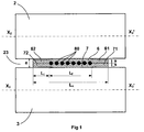
- the calendering device shown in figure 1 comprises two calender rolls 2 and 3 whose axes, respectively X 2 X 2 'and X 3 X 3 ', are substantially parallel between them.
- the space between the two cylinders defines an air gap 23, in which an upper continuous rubber sheet 6 flows, and a lower continuous rubber sheet 7.
- a sheet of reinforcing threads 80 is sandwiched between the two sheets of rubber, and the pressure generated by the cylinders at the gap, forces the rubber to enter the free spaces between the reinforcing threads so as to form, downstream of the gap, a composite product in which the reinforcing threads are coated with rubber.
- reinforcing thread 80 may be formed of reinforcing threads parallel to each other in the longitudinal direction, which is the general case, but also comprise reinforcing threads having particular provisions with respect to the longitudinal direction. , by adopting holding means such as weft threads or any other equivalent arrangement to allow the sheet of reinforcement son to circulate continuously in the air gap of the rolls of the calender.
- rubber is here understood to mean any composition comprising a non-vulcanized, diene or non-diene plastic elastomer mixture, combined with reinforcing fillers and with other elements such as vulcanizing products or any other type of additive material. .
- Each of the rubber sheets has a width L s greater than the width L f of the sheet of reinforcing threads, revealing two lateral edges respectively 61, 62 and 71, 72, of width L i , and to the right of which it there are no reinforcing wires.
- the value of the gap e is adjusted so that the thick rubber sheets s fill, under the effect of pressure, the free volume available between the reinforcing son. It is then observed that, at the edge of the selvedges, in the absence of the volume of the reinforcing threads, the pressure exerted by the rolls on the rubber sheets is low, or even zero. As a result, the joining of the rubber sheets at the selvedges is of low quality, which is likely to cause incidents during the cutting operation of the selvedges downstream of the gap, as has already been the case. indicated in the introduction to this application.
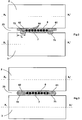
- the figure 2 illustrates a calendering device similar to the device described above.
- the method of implementation differs however in that the edges 71 and 72 of the lower rubber sheet 7 are folded on themselves and feed the volumes placed at the lateral ends of the sheet of reinforcing son 80.
- the figure 3 illustrates the general shape of the composite downstream of the gap, where there is good sealing of the edge 61 of the upper rubber sheet 61 with the edge 71 of the lower rubber sheet 7; and similarly of the edge 62 with the edge 72.
- the object of the invention is also to provide a particularly well adapted means for performing this fold of the selvedge on themselves while controlling the geometric position of the rubber sheets relative to the sheet of reinforcing son.
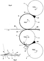
- the figure 4 illustrates a device comprising a calender formed cylinders 2 and 3 similar to the calender shown in the previous figures.
- This calender also comprises two additional cylinders respectively the cylinders 1 and 4 with axes X 1 X 1 'and X 4 X 4 ' substantially parallel to the axes X 2 X 2 'and X 3 X 3 ' of the calendering rolls 2 and 3.
- the cylinders 1 and 4 cooperate respectively with the cylinders 2 and 3 with which they form an upper air gap 12 and a lower air gap 34.
- This device which is widely used in industry, makes it possible simultaneously to manufacture continuous rubber sheets 6 and 7 in the upper and lower air gaps 12 and 34, at the input of which a continuous supply of a base material is placed.
- the manufacture of the composite product formed by the assembly of the ply of reinforcing threads 80 and the continuous rubber sheets is effected as previously in the gap 23 formed by the calendering rolls 2 and 3.
- This device comprises turning discs 9, arranged axially on either side of the lower rubber sheet 7, downstream of the gap 34, and upstream of the air gap 23 of the calendering rolls
- the figure 5 represents a detailed view of a turning disc 9, which comprises a conical surface 91 whose generatrices form a given angle ⁇ by relative to the axis of rotation xx 'of the reversing disc.
- the angle ⁇ can usefully be between 70 ° and 80 °. By way of example, good results have been obtained with an angle ⁇ of 78 °.
- the cylindrical portion of the turning disc has a height d of between 10 mm and 30 mm.
- the diameter of the disc can usefully be between 15 cm and 25 cm.
- the turning disc is intended to come into contact with the selvedges formed of a thin rubber product will avoid appear sharp corners between the different faces of the turning disc.
- the disc axis is arranged such that at the radially distal point P of the conical surface 91 of the turning disc 9 and the cylinder 3, the radially distal portion of the conical surface is substantially tangential to the surface of the cylinder 3.
- the generatrix of the conical surface is perpendicular to the radius R p of the calender roll 3.
- each turntable on a movable support (not shown) in a substantially radial direction of the calendering roll to allow an adjustable approach of the turntable to the surface of said roll.
- the support is activated a slight movement in the opposite direction over a distance corresponding to the desired game J.
- the same approach mechanism can also be used to make the system disengageable when its use is not required.
- these supports can be movable in an axial direction parallel to the axis of the calendering roll.
- the amplitude of the upturn, and consequently the position of the fold, can then be easily adjusted by changing the axial position of the flipper disc or by varying the speed of rotation of the disc.
- Each turning disc is rotated about its axis xx 'by suitable means (not shown).
- the rotational speed of the disc can be conveniently adjusted so that, at the point P, the circumferential speed of the disc is at least greater than the circumferential speed of the cylinder.
- the direction of rotation of the reversing discs is determined so that at the point of contact P the tangential speed of the disc is oriented axially towards the equator of the cylinder 3.
- this device is particularly advantageous in the case of a four-roll calender as described above, but it is possible to implement the reversing device according to the invention on a calender comprising only two calendering cylinders by adapting the feed of the calender so as to circulate upstream of the air gap 23, one of the two rubber sheets around the calender roll on which the reversing discs are mounted.
Landscapes
- Engineering & Computer Science (AREA)
- Mechanical Engineering (AREA)
- Textile Engineering (AREA)
- Life Sciences & Earth Sciences (AREA)
- Forests & Forestry (AREA)
- Chemical & Material Sciences (AREA)
- Composite Materials (AREA)
- Computer Vision & Pattern Recognition (AREA)
- Casting Or Compression Moulding Of Plastics Or The Like (AREA)
- Tyre Moulding (AREA)
Claims (15)
- Vorrichtung zum Kalandern, aufweisend mindestens zwei Kalanderwalzen (3, 4), welche einen Spalt (23) bilden, der dafür vorgesehen ist, eine kontinuierliche Bahn von Verstärkungsfäden (80), welche zwischen zwei kontinuierlichen Folien aus Kautschuk (6, 7) angeordnet sind, aufzunehmen, dadurch gekennzeichnet, dass sie stromaufwärts des Spalts (23) Mittel zum Wenden (9) aufweist, welche geeignet sind, die Seitenkanten (71, 72) mindestens einer Gummifolie (7) übereinander zusammen zu falten.
- Kalandervorrichtung nach Anspruch 1, bei welcher die Mittel zum Wenden von drehenden Wendescheiben (9) gebildet werden, welche axial beiderseits des Äquators einer Kalanderwalze (3) eingebaut sind, wobei jede der Wendescheiben eine konische Fläche (91) aufweist, deren Mantellinien einen gegebenen Winkel (α) in Bezug auf die Drehachse (xx') der Wendescheibe bilden, und bei der die Wendescheibe derartig eingebaut ist, dass der radial distale Abschnitt (P) der konischen Fläche (91) der Wendescheibe im Wesentlichen tangential zur Fläche der Kalanderwalze verläuft, ohne mit der Fläche in Kontakt zu geraten.
- Vorrichtung nach Anspruch 2, bei welcher der Abstand (j) zwischen dem radial distalen Abschnitt der Wendescheibe (P) und der Fläche der Kalanderwalze zwischen 0,1 mm und 1 mm liegt.
- Vorrichtung nach einem der Ansprüche 2 oder 3, bei welcher der Winkel (α), welcher durch die Mantellinien der konischen Fläche mit der Drehachse der Wendescheibe gebildet wird, zwischen 70° und 80° liegt.
- Kalandervorrichtung nach einem der Ansprüche 2 bis 4, bei welcher der Durchmesser einer Wendescheibe zwischen 15 cm und 25 cm liegt.
- Vorrichtung nach einem der Ansprüche 2 bis 5, bei welcher die Drehachse (xx') einer Wendescheibe im Wesentlichen senkrecht zur Drehachse (X3X3') der Kalanderwalze (3) verläuft.
- Kalandervorrichtung nach einem der Ansprüche 1 bis 6, bei welcher die Position der Wendemittel in der axialen Richtung parallel zur Achse (X3X3') der Kalanderwalzen einstellbar ist.
- Kalandervorrichtung nach einem der Ansprüche 1 bis 7, aufweisend zwei zusätzliche Walzen (1, 4), welche jeweils mit jeder der beiden Kalanderwalzen (2, 3) zusammenwirken und mit jeder dieser Walzen einen oberen Spalt (12) und einen unteren Spalt (34) bilden, welcher jeder dafür vorgesehen ist, eine Folie aus Kautschuk zu bewerkstelligen, und bei welcher die Mittel zum Wenden (9) stromabwärts vom oberen (12) oder unteren (34) Spalt angeordnet sind.
- Verfahren zum Kalandern einer kontinuierlichen Bahn aus Verstärkungsfäden (80) in dessen Verlauf:die Bahn aus Verstärkungsfäden zwischen eine obere, kontinuierliche Folie aus Kautschuk (6) und eine untere, kontinuierliche Folie aus Kautschuk (7) angeordnet wird, wobei die Folien aus Kautschuk eine Breite (Ls) besitzen, welche größer als die Breite (Lf) der Bahn aus Verstärkungsfäden ist, derartig, dass die beiden seitlichen Abschnitte der Folien aus Kautschuk, welche sich nicht gegenüber der Bahn aus Verstärkungsfäden befinden, Kanten (61, 62 und 71, 72) bilden,die im vorhergehenden Schritt gebildete Gesamtheit in den Spalt (23) eines Kalanders eingeführt wird, welcher mindestens zwei Walzen (2, 3) aufweist, um den Kautschuk in die Räume zwischen den Verstärkungsfäden eindringen zu lassen,dadurch gekennzeichnet, dass vor dem Einführen der Bahn aus Verstärkungsfäden und der Folien aus Kautschuk in den Spalt (23) des Kalanders die Kanten (71, 72) von mindestens einer der Folien aus Kautschuk (7) übereinander zusammen gefaltet werden.
- Verfahren zum Kalandern nach Anspruch 9, bei welchem die Falte der Kanten (71, 72) im Bereich ihrer jeweiligen halben Breiten gebildet wird.
- Verfahren zum Kalandern nach einem der Ansprüche 9 oder 10, bei welchem
man stromaufwärts des Spalts (23) des Kalanders eine Folie aus Kautschuk (7) um eine der Kalanderwalzen (3) sich bewegen lässt, welche mit einer Vorrichtung nach einem der Ansprüche 2 bis 8 ausgerüstet ist,
die Wendescheiben (9) axial in Drehung jeder der Kanten (71, 72) derartig näher gebracht werden, dass die Kanten durch die Wendescheibe angehoben werden und sich auf sich selbst in Richtung des Äquators der Walze unter der Einwirkung der Drehung der Wendescheibe (9) zusammenfalten. - Verfahren zum Kalandern nach Anspruch 11, bei welchem die Wendescheiben (9) derartig in Drehung versetzt werden, dass die Tangentialgeschwindigkeit im Bereich des radial distalen Abschnitts (P) der Wendescheiben im Wesentlichen parallel zur Achse (X3X3') der Walze (3) in Richtung des Äquators der Walze gerichtet wird.
- Verfahren zum Kalandern nach einem der Ansprüche 11 oder 12, bei welchem die Wendescheiben (9) derartig in Drehung versetzt werden, dass die Umfangsgeschwindigkeit im Bereich des radial distalen Abschnitts (P) der Wendescheiben größer als die Umfangsgeschwindigkeit der Kalanderwalze (3) ist.
- Verfahren zum Kalandern nach einem der Ansprüche 9 bis 13, bei welchem stromabwärts des von den Kalanderwalzen (2, 3) gebildeten Spalts (23) die Seitenkanten geschnitten werden.
- Verfahren zum Kalandern nach einem der Ansprüche 9 bis 14, bei welchem die Bahn aus Verstärkungsfäden (80) von Verstärkungsfäden gebildet wird, welche untereinander parallel sind und einen Winkel von Null mit der longitudinalen Richtung der Bahn bilden.
Applications Claiming Priority (2)
| Application Number | Priority Date | Filing Date | Title |
|---|---|---|---|
| FR1250551A FR2985937B1 (fr) | 2012-01-19 | 2012-01-19 | Dispositif et procede de retournement des lisieres sur une calandre |
| PCT/EP2013/050774 WO2013107786A1 (fr) | 2012-01-19 | 2013-01-17 | Dispositif et procede de retournement des lisieres sur une calandre |
Publications (2)
| Publication Number | Publication Date |
|---|---|
| EP2804750A1 EP2804750A1 (de) | 2014-11-26 |
| EP2804750B1 true EP2804750B1 (de) | 2016-06-29 |
Family
ID=47559510
Family Applications (1)
| Application Number | Title | Priority Date | Filing Date |
|---|---|---|---|
| EP13700322.4A Active EP2804750B1 (de) | 2012-01-19 | 2013-01-17 | Vorrichtung und verfahren zum wenden von kanten auf einem kalander |
Country Status (5)
| Country | Link |
|---|---|
| US (1) | US9566727B2 (de) |
| EP (1) | EP2804750B1 (de) |
| CN (1) | CN104053541B (de) |
| FR (1) | FR2985937B1 (de) |
| WO (1) | WO2013107786A1 (de) |
Families Citing this family (3)
| Publication number | Priority date | Publication date | Assignee | Title |
|---|---|---|---|---|
| FR3044254B1 (fr) * | 2015-12-01 | 2017-11-24 | Michelin & Cie | Installation de calandrage pour nappes de renfort pour pneumatique |
| JP7138079B2 (ja) * | 2019-05-17 | 2022-09-15 | Toyo Tire株式会社 | ビードコア被覆方法及びビードコア被覆装置 |
| FR3099890A1 (fr) * | 2019-08-12 | 2021-02-19 | Compagnie Generale Des Etablissements Michelin | Machine de Guidage et de Maintien des Fils et Méthode d’Utilisation |
Family Cites Families (5)
| Publication number | Priority date | Publication date | Assignee | Title |
|---|---|---|---|---|
| US2038328A (en) * | 1935-06-05 | 1936-04-21 | Seiberling Rubber Co | Manufacture of rubberized fabrics |
| CA970518A (en) * | 1971-09-14 | 1975-07-08 | Romain E. Loeffler | Mineral fiber mat forming apparatus |
| JP2005262672A (ja) * | 2004-03-18 | 2005-09-29 | Sumitomo Rubber Ind Ltd | スチールコードプライの製造方法、スチールコードプライ及びそれを用いた空気入りタイヤ |
| DE102006010469A1 (de) * | 2006-03-07 | 2007-09-13 | GM Global Technology Operations, Inc., Detroit | Bördeleinrichtung sowie Verfahren zum Rollbördeln von Werkstücken |
| DE102006014142A1 (de) * | 2006-03-28 | 2007-10-04 | Continental Aktiengesellschaft | Verfahren zur Herstellung einer Materialbahn und Materialbahn |
-
2012
- 2012-01-19 FR FR1250551A patent/FR2985937B1/fr not_active Expired - Fee Related
-
2013
- 2013-01-17 US US14/372,293 patent/US9566727B2/en active Active
- 2013-01-17 CN CN201380005545.5A patent/CN104053541B/zh active Active
- 2013-01-17 WO PCT/EP2013/050774 patent/WO2013107786A1/fr not_active Ceased
- 2013-01-17 EP EP13700322.4A patent/EP2804750B1/de active Active
Also Published As
| Publication number | Publication date |
|---|---|
| FR2985937A1 (fr) | 2013-07-26 |
| CN104053541A (zh) | 2014-09-17 |
| US9566727B2 (en) | 2017-02-14 |
| WO2013107786A1 (fr) | 2013-07-25 |
| FR2985937B1 (fr) | 2014-03-07 |
| US20150000828A1 (en) | 2015-01-01 |
| CN104053541B (zh) | 2016-10-26 |
| EP2804750A1 (de) | 2014-11-26 |
Similar Documents
| Publication | Publication Date | Title |
|---|---|---|
| EP1867467A1 (de) | Vorrichtung und Verfahren zum Auflegen einer Gehäuseverstärkungslage | |
| FR2991234A1 (fr) | Procede de fabrication d'une paroi flexible dans un sillon de bande de roulement pour pneumatique | |
| WO2012080629A1 (fr) | Procédé et installation de fabrication d'une pneumatique au moyen d'une nappe comprenant deux gommes et ebauche cru de pneumatique | |
| WO2010106265A1 (fr) | Dispositif de decoupe d'emballages thermoformes, a double actionneur, procede de decoupe correspondant, et machine d'emballage incorporant un tel dispositif | |
| WO2013107786A1 (fr) | Dispositif et procede de retournement des lisieres sur une calandre | |
| FR2937625A1 (fr) | Tapis de transfert de nappes comportant des renforts metalliques | |
| EP3383617B1 (de) | Kalandriereinrichtung für verstärkungslagen für reifen | |
| EP1674250B1 (de) | Aufbautrommel für Reifengürtel | |
| FR2882535A1 (fr) | Dispositif et procede de fabrication de nappes ondulees | |
| WO2009135827A1 (fr) | Installation de recyclage de pneumatiques usages comportant une tète de projection de fluide a haute pression | |
| EP2038065B1 (de) | Lochscheibe für einen fleischwolf | |
| EP2794296B1 (de) | Luftreifen und verfahren zur herstellung eines reifentriangulationsbandes | |
| EP2794252B1 (de) | Verfahren und vorrichtung zum perforierten schneiden einer verstärkungslage | |
| EP4221967B1 (de) | Verfahren zur herstellung einer optimierten schicht eines selbstdichtenden produkts | |
| EP3393742B1 (de) | Kalander umfassend eine rolle mit seitlichen vorsprüngen | |
| EP4222003B1 (de) | Reifen mit einer optimierten schicht aus selbstdichtendem produkt | |
| FR2975311A1 (fr) | Procede de reduction de granules de materiau elastomere, dispositif de reduction de granules de materiau elastomere faisant application, poudre obtenue par un tel procede et procede d'utilisation d'une telle poudre | |
| EP2254746B1 (de) | Verfahren und Vorrichtung zur Herstellung einer Verstärkung durch Wickeln eines Bands auf sich selbst | |
| EP3393772B1 (de) | Kalander umfassend eine ablösungsvorrichtung für die geformte mischung | |
| EP4601849A2 (de) | Verbesserte haltevorrichtung und zugehöriges herstellungsverfahren | |
| EP2520699A1 (de) | Roller zur Abdichtung eines Einlasses und Herstellungsverfahren | |
| WO2010052186A1 (fr) | Filiere d'extrusion a double profil |
Legal Events
| Date | Code | Title | Description |
|---|---|---|---|
| PUAI | Public reference made under article 153(3) epc to a published international application that has entered the european phase |
Free format text: ORIGINAL CODE: 0009012 |
|
| 17P | Request for examination filed |
Effective date: 20140819 |
|
| AK | Designated contracting states |
Kind code of ref document: A1 Designated state(s): AL AT BE BG CH CY CZ DE DK EE ES FI FR GB GR HR HU IE IS IT LI LT LU LV MC MK MT NL NO PL PT RO RS SE SI SK SM TR |
|
| DAX | Request for extension of the european patent (deleted) | ||
| REG | Reference to a national code |
Ref country code: DE Ref legal event code: R079 Ref document number: 602013008905 Country of ref document: DE Free format text: PREVIOUS MAIN CLASS: B29D0030380000 Ipc: B29L0030000000 |
|
| GRAP | Despatch of communication of intention to grant a patent |
Free format text: ORIGINAL CODE: EPIDOSNIGR1 |
|
| INTG | Intention to grant announced |
Effective date: 20160111 |
|
| RIC1 | Information provided on ipc code assigned before grant |
Ipc: B29L 30/00 20060101AFI20151218BHEP Ipc: B29C 53/04 20060101ALI20151218BHEP |
|
| GRAS | Grant fee paid |
Free format text: ORIGINAL CODE: EPIDOSNIGR3 |
|
| GRAA | (expected) grant |
Free format text: ORIGINAL CODE: 0009210 |
|
| AK | Designated contracting states |
Kind code of ref document: B1 Designated state(s): AL AT BE BG CH CY CZ DE DK EE ES FI FR GB GR HR HU IE IS IT LI LT LU LV MC MK MT NL NO PL PT RO RS SE SI SK SM TR |
|
| REG | Reference to a national code |
Ref country code: GB Ref legal event code: FG4D Free format text: NOT ENGLISH |
|
| REG | Reference to a national code |
Ref country code: CH Ref legal event code: EP |
|
| REG | Reference to a national code |
Ref country code: AT Ref legal event code: REF Ref document number: 808750 Country of ref document: AT Kind code of ref document: T Effective date: 20160715 |
|
| REG | Reference to a national code |
Ref country code: IE Ref legal event code: FG4D Free format text: LANGUAGE OF EP DOCUMENT: FRENCH |
|
| REG | Reference to a national code |
Ref country code: DE Ref legal event code: R096 Ref document number: 602013008905 Country of ref document: DE |
|
| REG | Reference to a national code |
Ref country code: NL Ref legal event code: FP |
|
| REG | Reference to a national code |
Ref country code: LT Ref legal event code: MG4D |
|
| PG25 | Lapsed in a contracting state [announced via postgrant information from national office to epo] |
Ref country code: FI Free format text: LAPSE BECAUSE OF FAILURE TO SUBMIT A TRANSLATION OF THE DESCRIPTION OR TO PAY THE FEE WITHIN THE PRESCRIBED TIME-LIMIT Effective date: 20160629 Ref country code: LT Free format text: LAPSE BECAUSE OF FAILURE TO SUBMIT A TRANSLATION OF THE DESCRIPTION OR TO PAY THE FEE WITHIN THE PRESCRIBED TIME-LIMIT Effective date: 20160629 Ref country code: NO Free format text: LAPSE BECAUSE OF FAILURE TO SUBMIT A TRANSLATION OF THE DESCRIPTION OR TO PAY THE FEE WITHIN THE PRESCRIBED TIME-LIMIT Effective date: 20160929 |
|
| PG25 | Lapsed in a contracting state [announced via postgrant information from national office to epo] |
Ref country code: SE Free format text: LAPSE BECAUSE OF FAILURE TO SUBMIT A TRANSLATION OF THE DESCRIPTION OR TO PAY THE FEE WITHIN THE PRESCRIBED TIME-LIMIT Effective date: 20160629 Ref country code: HR Free format text: LAPSE BECAUSE OF FAILURE TO SUBMIT A TRANSLATION OF THE DESCRIPTION OR TO PAY THE FEE WITHIN THE PRESCRIBED TIME-LIMIT Effective date: 20160629 Ref country code: LV Free format text: LAPSE BECAUSE OF FAILURE TO SUBMIT A TRANSLATION OF THE DESCRIPTION OR TO PAY THE FEE WITHIN THE PRESCRIBED TIME-LIMIT Effective date: 20160629 Ref country code: GR Free format text: LAPSE BECAUSE OF FAILURE TO SUBMIT A TRANSLATION OF THE DESCRIPTION OR TO PAY THE FEE WITHIN THE PRESCRIBED TIME-LIMIT Effective date: 20160930 Ref country code: RS Free format text: LAPSE BECAUSE OF FAILURE TO SUBMIT A TRANSLATION OF THE DESCRIPTION OR TO PAY THE FEE WITHIN THE PRESCRIBED TIME-LIMIT Effective date: 20160629 |
|
| REG | Reference to a national code |
Ref country code: AT Ref legal event code: MK05 Ref document number: 808750 Country of ref document: AT Kind code of ref document: T Effective date: 20160629 |
|
| REG | Reference to a national code |
Ref country code: FR Ref legal event code: PLFP Year of fee payment: 5 |
|
| PG25 | Lapsed in a contracting state [announced via postgrant information from national office to epo] |
Ref country code: RO Free format text: LAPSE BECAUSE OF FAILURE TO SUBMIT A TRANSLATION OF THE DESCRIPTION OR TO PAY THE FEE WITHIN THE PRESCRIBED TIME-LIMIT Effective date: 20160629 Ref country code: SK Free format text: LAPSE BECAUSE OF FAILURE TO SUBMIT A TRANSLATION OF THE DESCRIPTION OR TO PAY THE FEE WITHIN THE PRESCRIBED TIME-LIMIT Effective date: 20160629 Ref country code: IT Free format text: LAPSE BECAUSE OF FAILURE TO SUBMIT A TRANSLATION OF THE DESCRIPTION OR TO PAY THE FEE WITHIN THE PRESCRIBED TIME-LIMIT Effective date: 20160629 Ref country code: CZ Free format text: LAPSE BECAUSE OF FAILURE TO SUBMIT A TRANSLATION OF THE DESCRIPTION OR TO PAY THE FEE WITHIN THE PRESCRIBED TIME-LIMIT Effective date: 20160629 Ref country code: IS Free format text: LAPSE BECAUSE OF FAILURE TO SUBMIT A TRANSLATION OF THE DESCRIPTION OR TO PAY THE FEE WITHIN THE PRESCRIBED TIME-LIMIT Effective date: 20161029 Ref country code: EE Free format text: LAPSE BECAUSE OF FAILURE TO SUBMIT A TRANSLATION OF THE DESCRIPTION OR TO PAY THE FEE WITHIN THE PRESCRIBED TIME-LIMIT Effective date: 20160629 |
|
| PG25 | Lapsed in a contracting state [announced via postgrant information from national office to epo] |
Ref country code: AT Free format text: LAPSE BECAUSE OF FAILURE TO SUBMIT A TRANSLATION OF THE DESCRIPTION OR TO PAY THE FEE WITHIN THE PRESCRIBED TIME-LIMIT Effective date: 20160629 Ref country code: ES Free format text: LAPSE BECAUSE OF FAILURE TO SUBMIT A TRANSLATION OF THE DESCRIPTION OR TO PAY THE FEE WITHIN THE PRESCRIBED TIME-LIMIT Effective date: 20160629 Ref country code: PL Free format text: LAPSE BECAUSE OF FAILURE TO SUBMIT A TRANSLATION OF THE DESCRIPTION OR TO PAY THE FEE WITHIN THE PRESCRIBED TIME-LIMIT Effective date: 20160629 Ref country code: SM Free format text: LAPSE BECAUSE OF FAILURE TO SUBMIT A TRANSLATION OF THE DESCRIPTION OR TO PAY THE FEE WITHIN THE PRESCRIBED TIME-LIMIT Effective date: 20160629 Ref country code: PT Free format text: LAPSE BECAUSE OF FAILURE TO SUBMIT A TRANSLATION OF THE DESCRIPTION OR TO PAY THE FEE WITHIN THE PRESCRIBED TIME-LIMIT Effective date: 20161031 |
|
| REG | Reference to a national code |
Ref country code: DE Ref legal event code: R097 Ref document number: 602013008905 Country of ref document: DE |
|
| PG25 | Lapsed in a contracting state [announced via postgrant information from national office to epo] |
Ref country code: DK Free format text: LAPSE BECAUSE OF FAILURE TO SUBMIT A TRANSLATION OF THE DESCRIPTION OR TO PAY THE FEE WITHIN THE PRESCRIBED TIME-LIMIT Effective date: 20160629 Ref country code: BE Free format text: LAPSE BECAUSE OF NON-PAYMENT OF DUE FEES Effective date: 20170131 |
|
| 26N | No opposition filed |
Effective date: 20170330 |
|
| PLBE | No opposition filed within time limit |
Free format text: ORIGINAL CODE: 0009261 |
|
| STAA | Information on the status of an ep patent application or granted ep patent |
Free format text: STATUS: NO OPPOSITION FILED WITHIN TIME LIMIT |
|
| PG25 | Lapsed in a contracting state [announced via postgrant information from national office to epo] |
Ref country code: SI Free format text: LAPSE BECAUSE OF FAILURE TO SUBMIT A TRANSLATION OF THE DESCRIPTION OR TO PAY THE FEE WITHIN THE PRESCRIBED TIME-LIMIT Effective date: 20160629 Ref country code: BG Free format text: LAPSE BECAUSE OF FAILURE TO SUBMIT A TRANSLATION OF THE DESCRIPTION OR TO PAY THE FEE WITHIN THE PRESCRIBED TIME-LIMIT Effective date: 20160929 |
|
| REG | Reference to a national code |
Ref country code: CH Ref legal event code: PL |
|
| GBPC | Gb: european patent ceased through non-payment of renewal fee |
Effective date: 20170117 |
|
| PG25 | Lapsed in a contracting state [announced via postgrant information from national office to epo] |
Ref country code: MC Free format text: LAPSE BECAUSE OF FAILURE TO SUBMIT A TRANSLATION OF THE DESCRIPTION OR TO PAY THE FEE WITHIN THE PRESCRIBED TIME-LIMIT Effective date: 20160629 |
|
| PG25 | Lapsed in a contracting state [announced via postgrant information from national office to epo] |
Ref country code: CH Free format text: LAPSE BECAUSE OF NON-PAYMENT OF DUE FEES Effective date: 20170131 Ref country code: LI Free format text: LAPSE BECAUSE OF NON-PAYMENT OF DUE FEES Effective date: 20170131 |
|
| REG | Reference to a national code |
Ref country code: IE Ref legal event code: MM4A |
|
| PG25 | Lapsed in a contracting state [announced via postgrant information from national office to epo] |
Ref country code: GB Free format text: LAPSE BECAUSE OF NON-PAYMENT OF DUE FEES Effective date: 20170117 Ref country code: LU Free format text: LAPSE BECAUSE OF NON-PAYMENT OF DUE FEES Effective date: 20170117 |
|
| REG | Reference to a national code |
Ref country code: FR Ref legal event code: PLFP Year of fee payment: 6 |
|
| REG | Reference to a national code |
Ref country code: BE Ref legal event code: MM Effective date: 20170131 |
|
| PG25 | Lapsed in a contracting state [announced via postgrant information from national office to epo] |
Ref country code: IE Free format text: LAPSE BECAUSE OF NON-PAYMENT OF DUE FEES Effective date: 20170117 |
|
| PG25 | Lapsed in a contracting state [announced via postgrant information from national office to epo] |
Ref country code: MT Free format text: LAPSE BECAUSE OF FAILURE TO SUBMIT A TRANSLATION OF THE DESCRIPTION OR TO PAY THE FEE WITHIN THE PRESCRIBED TIME-LIMIT Effective date: 20160629 |
|
| PG25 | Lapsed in a contracting state [announced via postgrant information from national office to epo] |
Ref country code: AL Free format text: LAPSE BECAUSE OF FAILURE TO SUBMIT A TRANSLATION OF THE DESCRIPTION OR TO PAY THE FEE WITHIN THE PRESCRIBED TIME-LIMIT Effective date: 20160629 |
|
| PG25 | Lapsed in a contracting state [announced via postgrant information from national office to epo] |
Ref country code: HU Free format text: LAPSE BECAUSE OF FAILURE TO SUBMIT A TRANSLATION OF THE DESCRIPTION OR TO PAY THE FEE WITHIN THE PRESCRIBED TIME-LIMIT; INVALID AB INITIO Effective date: 20130117 |
|
| PG25 | Lapsed in a contracting state [announced via postgrant information from national office to epo] |
Ref country code: CY Free format text: LAPSE BECAUSE OF FAILURE TO SUBMIT A TRANSLATION OF THE DESCRIPTION OR TO PAY THE FEE WITHIN THE PRESCRIBED TIME-LIMIT Effective date: 20160629 |
|
| PG25 | Lapsed in a contracting state [announced via postgrant information from national office to epo] |
Ref country code: MK Free format text: LAPSE BECAUSE OF FAILURE TO SUBMIT A TRANSLATION OF THE DESCRIPTION OR TO PAY THE FEE WITHIN THE PRESCRIBED TIME-LIMIT Effective date: 20160629 |
|
| PG25 | Lapsed in a contracting state [announced via postgrant information from national office to epo] |
Ref country code: TR Free format text: LAPSE BECAUSE OF FAILURE TO SUBMIT A TRANSLATION OF THE DESCRIPTION OR TO PAY THE FEE WITHIN THE PRESCRIBED TIME-LIMIT Effective date: 20160629 |
|
| PGFP | Annual fee paid to national office [announced via postgrant information from national office to epo] |
Ref country code: NL Payment date: 20260121 Year of fee payment: 14 |
|
| PGFP | Annual fee paid to national office [announced via postgrant information from national office to epo] |
Ref country code: DE Payment date: 20260121 Year of fee payment: 14 |
|
| PGFP | Annual fee paid to national office [announced via postgrant information from national office to epo] |
Ref country code: FR Payment date: 20260123 Year of fee payment: 14 |