EP2804294A2 - Bobbin and rotary electric machine comprising such a bobbin - Google Patents
Bobbin and rotary electric machine comprising such a bobbin Download PDFInfo
- Publication number
- EP2804294A2 EP2804294A2 EP14158782.4A EP14158782A EP2804294A2 EP 2804294 A2 EP2804294 A2 EP 2804294A2 EP 14158782 A EP14158782 A EP 14158782A EP 2804294 A2 EP2804294 A2 EP 2804294A2
- Authority
- EP
- European Patent Office
- Prior art keywords
- winding
- bobbin
- coil wire
- coil
- end portion
- Prior art date
- Legal status (The legal status is an assumption and is not a legal conclusion. Google has not performed a legal analysis and makes no representation as to the accuracy of the status listed.)
- Withdrawn
Links
Images









Classifications
-
- H—ELECTRICITY
- H02—GENERATION; CONVERSION OR DISTRIBUTION OF ELECTRIC POWER
- H02K—DYNAMO-ELECTRIC MACHINES
- H02K3/00—Details of windings
- H02K3/46—Fastening of windings on the stator or rotor structure
- H02K3/50—Fastening of winding heads, equalising connectors, or connections thereto
-
- H—ELECTRICITY
- H02—GENERATION; CONVERSION OR DISTRIBUTION OF ELECTRIC POWER
- H02K—DYNAMO-ELECTRIC MACHINES
- H02K3/00—Details of windings
- H02K3/32—Windings characterised by the shape, form or construction of the insulation
- H02K3/34—Windings characterised by the shape, form or construction of the insulation between conductors or between conductor and core, e.g. slot insulation
- H02K3/345—Windings characterised by the shape, form or construction of the insulation between conductors or between conductor and core, e.g. slot insulation between conductor and core, e.g. slot insulation
-
- H—ELECTRICITY
- H02—GENERATION; CONVERSION OR DISTRIBUTION OF ELECTRIC POWER
- H02K—DYNAMO-ELECTRIC MACHINES
- H02K1/00—Details of the magnetic circuit
- H02K1/06—Details of the magnetic circuit characterised by the shape, form or construction
- H02K1/12—Stationary parts of the magnetic circuit
- H02K1/14—Stator cores with salient poles
- H02K1/146—Stator cores with salient poles consisting of a generally annular yoke with salient poles
- H02K1/148—Sectional cores
-
- H—ELECTRICITY
- H02—GENERATION; CONVERSION OR DISTRIBUTION OF ELECTRIC POWER
- H02K—DYNAMO-ELECTRIC MACHINES
- H02K2203/00—Specific aspects not provided for in the other groups of this subclass relating to the windings
- H02K2203/12—Machines characterised by the bobbins for supporting the windings
-
- H—ELECTRICITY
- H02—GENERATION; CONVERSION OR DISTRIBUTION OF ELECTRIC POWER
- H02K—DYNAMO-ELECTRIC MACHINES
- H02K3/00—Details of windings
- H02K3/46—Fastening of windings on the stator or rotor structure
- H02K3/52—Fastening salient pole windings or connections thereto
Definitions
- An embodiment disclosed herein relates to a bobbin and a rotary electric machine provided with the bobbin.
- a rotary electric machine that includes an armature core, teeth protruding inward from the armature core at a regular interval in a circumferential direction, armature coils wound around the teeth in a so-called concentrated winding manner in which a coil of a single pole and a single phase is concentratedly wound around each of the teeth, and bobbins mounted within slots provided between the adjacent teeth and configured to accommodate the armature coils (see, e.g., Japanese Patent Application Publication No. H09-308142 ).
- the ends of coil wires drawn out from the respective bobbins are connected by a wire connection substrate in a specified wire connection pattern. If the wire connection pattern formed in the wire connection substrate grows complex, it is necessary to use a multi-layer substrate. This may possibly lead to an increase in the size of the rotary electric machine and an increase in the costs. Accordingly, there is a need to simplify the wire connection pattern of the wire connection substrate.
- the embodiment disclosed herein provides a bobbin capable of simplifying a wire connection pattern of a wire connection substrate, and a rotary electric machine provided with the bobbin.
- a bobbin adapted to be mounted to a stator core of a rotary electric machine and configured to electrically insulate the stator core from a coil wire to be wound around the bobbin, the bobbin including: a coil winding portion around which the coil wire is to be wound; and a terminal fixing portion to which a winding starting end portion and a winding finishing end portion of the coil wire are to be fixed, wherein the terminal fixing portion includes a first groove configured to guide a winding starting section extending from the winding starting end portion of the coil wire to a winding starting position of the coil winding portion and a second groove configured to guide a winding finishing section extending from a winding finishing position of the coil winding portion to the winding finishing end portion of the coil wire to intersect the winding starting section when seen in an axial direction.
- the rotary electric machine 1 includes a stator 2 and a rotor 3.
- the rotary electric machine 1 is an inner-rotor-type motor in which the rotor 3 is arranged inside the stator 2.
- the rotary electric machine 1 may be a generator.
- the stator 2 is arranged on an inner circumferential surface of a frame 4 through a laminated core ring 5 to radially face the rotor 3.
- the stator 2 includes a laminated core ring 5, a laminated core body 6 (a stator core), a plurality of bobbins 20 mounted to the laminated core body 6 and a plurality of coil wires 7 wound on the bobbins 20.
- the bobbins 20 are made of an insulating material (a resin or the like) in order to electrically insulate the laminated core body 6 from the coil wires 7.
- a substrate 8 (a wire connection substrate) is arranged at one axial end (the left end in Fig. 1 ) of the bobbins 20.
- the circuit arranged in the substrate 8 and the coil wires 7 wound on the bobbins 20 are electrically connected to each other through two square-bar-shaped pin terminals 9. As shown in Fig. 3 , a winding starting end portion 7a and a winding finishing end portion 7b of each of the coil wires 7 are wrapped around the corresponding pin terminals 9 and are fixed by, e.g., solders (not shown).
- the rotor 3 is formed of a permanent magnet and is provided on an outer circumferential surface of a shaft 10.
- the shaft 10 is rotatably supported by a load-side bearing 12 whose outer race is fitted to a load-side bracket 11 provided at the load side (the right side in Fig. 1 ) of the frame 4 and a counter-load-side bearing 14 whose outer race is fitted to a counter-load-side bracket 13 provided at the counter-load side (the opposite side to the load side, i.e., the left side in Fig. 1 ) of the frame 4.
- An encoder 15 is provided at the counter-load-side end portion of the shaft 10.
- the encoder 15 is covered with an encoder cover 16.
- the laminated core body 6 is provided with a plurality of (e.g., twelve in Fig. 2 ) radial projections 18 which protrude radially outward.
- the bobbins 20 wound with the coil wires 7 are mounted to the respective projections 18 from the radial outer side. As shown in Fig. 2 , in each of recesses 19 between the adjacent projections 18, the side portions of the bobbins 20 mounted to the respective projections 18, at which the winding layers of the coil wires 7 face each other, are disposed in a spaced-apart relationship with each other.
- the bobbins 6 wound with the coil wires 7 are mounted to the laminated core body 6 and are then fixed to the inner circumferential surface of the laminated core ring 5 having an annular shape, thereby forming the stator 2.
- the stator 2 thus formed is mounted to the inner circumferential surface of the frame 4. Thereafter, a resin is introduced into the recesses 19, whereby the bobbins 20 and the coil wires 7 are molded with the resin.
- the rotary electric machine 1 is a rotary induction motor using a three-phase alternating current.
- slot combination in section of the rotary electric machine 1 includes ten poles and twelve slots (10P and 12S) in case of a permanent magnet synchronous motor.
- the bobbins 20 namely, the bobbins 20A and 20B
- the bobbins 20A and 20B corresponding to the coils having the same phase but differing 180 degrees in electrical angle from each other are disposed adjacent to each other.
- U, V and W designate the bobbins 20 corresponding to a U-phase, a V-phase and a W-phase.
- U , V and W designate the bobbins 20 differing 180 degrees in electrical angle from the bobbins U, V and W (This holds true in Fig. 7 ).
- the relationship of the wire connection patterns of individual phases in the substrate 8 to be described below is indicated by double-dot chain lines or single-dot chain lines.
- each of the bobbins 20 the bobbins 20 (twelve bobbins 20 in the present embodiment) mounted to the laminated core body 6 has the same structure. As shown in Figs.
- each of the bobbins 20 includes a substantially quadrilateral frame-like trunk portion (a coil winding portion) 21 wound with the coil wire 7, a first flange portion 22 formed along the edge of one end of the trunk portion 21, a second flange portion 23 formed along the edge of the other end of the trunk portion 21, and a substrate mounting portion 24 installed in the second flange portion 23 to mount thereon the substrate 8 and provided with a terminal fixing portion for fixing the winding starting end portion 7a and the winding finishing end portion 7b of the coil wire 7, which will be described later.
- the trunk portion 21 includes coil winding surfaces 21a opposite to each other in the axial direction 10a of the stator 2 (the left-right direction in Fig. 1 and the up-down direction in Fig. 4 ) and coil winding surfaces 21b opposite to each other in the circumferential direction of the stator 2.
- the trunk portion 21 is formed into a hollow prismatic shape and is provided with a hollow portion 25 into which the projection 18 of the laminated core body 6 is inserted.
- the first flange portion 22 is formed into a rectangular shape extending along the edge of the one end of the trunk portion 21 to open one end of the hollow portion 25.
- the second flange portion 23 is formed into a rectangular shape extending along the edge of the other end of the trunk portion 21 to open the other end of the hollow portion 25.
- the second flange portion 23 protrudes from the trunk portion 21 to be larger in size than the first flange portion 22.
- the substrate mounting portion 24 is provided at one short side (the upper side in Fig. 4 ) of the second flange portion 23.
- Two pin terminals 9 are inserted into the substrate mounting portion 24 to protrude from the upper surface of the substrate mounting portion 24.
- the winding starting end 7a and the winding finishing end 7b of the coil wire 7 are respectively fixed to the pin terminals 9.
- the surface of the substrate mounting portion 24 into which the pin terminals 9 are inserted will be referred to as a "terminal surface 24a".
- bobbin 20A Two kinds of coil winding methods are employed in the bobbins 20 in accordance with the present embodiment. Specifically, in the bobbin 20A shown in Fig. 7 , a winding starting section X from the winding starting end portion 7a of the coil wire 7 to a winding starting position 7c of the trunk portion 21 and a winding finishing section Y from a winding finishing position 7d of the trunk portion 21 to the winding finishing end portion 7b of the coil wire 7 intersect each other when seen in the axial direction 10a.
- the bobbin that employs this coil winding method will be sometimes referred to as "bobbin 20A" (first bobbin) herein below.
- the winding starting section X extending from the winding starting end portion 7a of the coil wire 7 to the winding starting position 7c of the trunk portion 21 and the winding finishing section Y extending from the winding finishing position 7d of the trunk portion 21 to the winding finishing end portion 7b do not intersect each other when seen in the axial direction 10a.
- the bobbin that employs this coil winding method will be sometimes referred to as "bobbin 20B" (second bobbin) herein below.
- the terminal surface 24a of the substrate mounting portion 24 has a structure that enables the winding starting section X and the winding finishing section Y of the coil wire 7 to easily intersect each other. Specifically, as shown in Figs. 4 to 6 , a first groove 24b which guides the winding starting section X of the coil wire 7 and a second groove 24c which guides the winding finishing section Y of the coil wire 7 to intersect the winding starting section X are provided in the terminal surface 24a of the substrate mounting portion 24. A third groove 24d and a fourth groove 24e, which respectively guide the winding starting section X and the winding finishing section Y of the coil wire 7 not to intersect each other, are provided in the terminal surface 24a of the substrate mounting portion 24.
- a recess 24h deeper than the grooves 24b to 24d is formed in an end portion of the third groove 24d at the side of the trunk portion 21.
- the recess 24h guides the winding starting section X of the coil wire 7 to the winding starting position 7c of the trunk portion 21.
- the coils 14 guided by the first groove 24b is fitted in the recess 24h.
- a height difference occurs between the winding starting section X and the winding finishing section Y of the coil wire 7. This makes it possible to have the winding starting section X and the winding finishing section Y intersect each other while avoiding mutual interference of the winding starting section X and the winding finishing section Y.
- pin holes 24A to 24D into which the pin terminals 9 are inserted, are formed in the terminal surface 24a of the substrate mounting portion 24.
- the two pin terminals 9 are selectively inserted into one of the pin holes 24A and 24C and one of the pin holes 24B and 24D, respectively.
- the pin holes 24A and 24C are spaced apart by a predetermined distance in the rotation direction of the rotor 3 (in the direction indicated by an arrow A in Fig. 5 ).
- the pin holes 24B and 24D are spaced apart by a predetermined distance in the rotation direction of the rotor 3 (in the direction indicated by the arrow A in Fig. 5 ).
- the pin terminal 9 (first pin) for winding the winding starting end portion 7a of the coil wire 7 is inserted into the pin hole 24A (first pin hole), and the pin terminal 9 (second pin) for winding the winding finishing end portion 7b of the coil wire 7 is inserted into the pin hole 24B (second pin hole).
- the pin terminal 9 (first pin) for winding the winding starting end portion 7a of the coil wire 7 is inserted into the pin hole 24D (first pin hole), and the pin terminal 9 (second pin) for winding the winding finishing end portion 7b of the coil wire 7 is inserted into the pin hole 24C (second pin hole).
- the insertion positions of the pin terminals 9 shown in Fig. 4 correspond to the bobbin 20B.
- the bobbin 20A and the bobbin 20B are alternately arranged to adjoin each other in the circumferential direction.
- the bobbins 20A and 20B corresponding to the coils differing 180 degrees in electrical angle from each other are disposed adjacent to each other.
- the positions of the winding starting end portion 7a and the winding finishing end portion 7b of the coil wire 7 in the bobbin 20A are opposite to those in the bobbin 20B along the rotation direction. Therefore, if the bobbin 20A and the bobbin 20B are disposed adjacent to each other, the winding finishing end portions 7b of the coil wires 7 can adjoin each other in each of the phases.
- Circuit patterns for connecting the coil wires 7 of the respective bobbins 20 in a predetermined pattern are formed in the substrate 8.
- Fig. 9 shows a circuit pattern formed on a front surface 8A of the substrate 8.
- Fig. 10 shows a circuit pattern formed on a rear surface 8B of the substrate 8.
- reference symbols PU, PV and PW designate wire connection patterns for connecting the winding finishing end portions 7b of the coil wires 7 of the adjacent bobbins 20A and 20B in each of the U-phase, the V-phase and the W-phase.
- Each of the wire connection patterns PU, PV and PW is formed by interconnecting adjacent through-holes 8a.
- each of bobbins 30 is configured such that, as in the bobbin 20B of the aforementioned embodiment, the winding starting section X and the winding finishing section Y of the coil wire 7 do not intersect each other when seen in the axial direction 10a. Further, the respective bobbins 30 employ the same coil winding method. For that reason, the positions of the winding starting end portions 7a and the winding finishing end portions 7b of the coil wires 7 in the respective bobbins 30 are in the same positional relationship along the rotation direction. As a result, the degree of freedom in arranging the wire connection patterns in the substrate 8 becomes lower, and the wire connection patterns grow complex.
- the circuit patterns of the substrate 8 into predetermined wire connection patterns by appropriately disposing the bobbins 20A and 20B (namely, by appropriately inverting the positions of the winding starting end portions 7a and the positions of the winding finishing end portions 7b).
- This makes it possible to increase the degree of freedom in arranging the wire connection patterns in the substrate 8. As a result, it becomes possible to simplify the circuit patterns of the substrate 8.
- the respective wire connection patterns PU, PV and PW are formed by interconnecting the adjacent through-holes 8a. This makes it possible to simplify the overall circuit patterns of the substrate 8.
- the substrate 8 As a result of the simplification of the circuit patterns of the substrate 8, it becomes possible, as in the present embodiment, to make the substrate 8 as a double-side substrate in which circuit patterns are formed on the opposite surfaces thereof. Therefore, as compared with a case where the substrate 8 is made from a multi-layer substrate, it is possible to reduce the size of the rotary electric machine 1 and to save the costs. Further, as a result of the simplification of the circuit patterns, it is possible to reduce the arrangement area of the circuit patterns. This makes it possible to increase the space in the substrate 8 in which a resin for molding the bobbins 20 flows. For example, in the substrate 8 shown in Figs. 9 and 10 , as compared with the substrate 38 of the comparative example shown in Figs. 12 and 13 , it is possible to increase the opening area just as much as the space S. Thus, a resin is easy to flow, which makes it possible to reduce generation of molding defects.
- the first groove 24b and the second groove 24c are formed in the terminal surface 24a of the substrate mounting portion 24.
- the first groove 24b guides the winding starting section X of the coil wire 7 of the bobbin 20A.
- the second groove 24c guides the winding finishing section Y of the coil wire 7 of the bobbin 20A.
- the substrate 8 can be mounted on the terminal surface 24a of the substrate mounting portion 24.
- the third groove 24d and the fourth groove 24e are additionally formed on the terminal surface 24a of the substrate mounting portion 24.
- the coil wire 7 can be wound using the first groove 24b and the second groove 24c such that the winding starting section X and the winding finishing section Y intersect each other when seen in the axial direction 10a.
- the coil wire 7 can be wound using the third groove 24d and the fourth groove 24e such that the winding starting section X and the winding finishing section Y do not intersect each other when seen in the axial direction 10a.
- the bobbins of the same shape provide two kinds of bobbins, namely the bobbin 20A in which the winding starting section X and the winding finishing section Y intersect each other when seen in the axial direction 10a and the bobbin 20B in which the winding starting section X and the winding finishing section Y do not intersect each other when seen in the axial direction 10a.
- the bobbins can be manufactured by one kind of mold. Therefore, as compared with a case where the bobbins are manufactured by two kinds of molds, it is possible to save the costs. Since the bobbins 20 of one kind are used, management of the bobbins 20 becomes easier.
- At least two pin holes are provided on the terminal surface 24a of the substrate mounting portion 24.
- the winding starting end portion 7a of the coil wire 7 is wrapped around the pin terminal 9 as the first pin inserted into the pin hole 24A.
- the winding finishing end portion 7b of the coil wire 7 is wrapped around the pin terminal 9 as the second pin inserted into the pin hole 24B.
- pin holes 24A to 24D are provided on the terminal surface 24a of the substrate mounting portion 24.
- Two pin holes 24A and 24C are spaced apart by a predetermined distance in the rotation direction. Accordingly, the position of the winding starting end portion 7a of the coil wire 7 in the bobbin 20A (the position of the winding finishing end portion 7b in the bobbin 20B) can be selected by inserting the pin terminal 9 into one of the pin holes 24A and 24C. Since the other second pin holes 24B and 24D are similarly arranged, it is possible to select the position of the winding finishing end portion 7b in the bobbin 20A (the position of the winding starting end portion 7a in the bobbin 20B).
- the pin hole 24B is selected in the bobbin 20A and the pin hole 24C is selected in the bobbin 20B such that the winding finishing end portions 7b of the coil wires 7 are positioned closer to each other.
- the pin hole 24A is selected for the winding starting end portion 7a of the coil wire 7 in the bobbin 20A and the pin hole 24D is selected for the winding starting end portion 7a of the coil wire 7 in the bobbin 20B such that the winding starting ends 7a of the adjacent coil wires 7 are positioned farther from each other.
- the rotary electric machine 1 is configured to have a slot combination of ten poles and twelve slots (10P-12S).
- 10P-12S ten poles and twelve slots
- the substrate 8 is mounted to the terminal surface 24a of the substrate mounting portion 24.
- a substrate mounting protrusion may be formed on the terminal surface 24a and a gap may be provided between the terminal surface 24a and the substrate 8.
- the bobbin 20' of the present modified example includes a substantially rectangular parallelepiped protrusion 26 arranged on the terminal surface 24a of the substrate mounting portion 24.
- the protrusion 26 has a mounting surface 26a to which the substrate 8 is mounted.
- a gap is formed between the terminal surface 24a and the substrate 8 mounted to the mounting surface 26a of the protrusion 26.
- the gap can be used to wrap the end portion of the coil wire 7.
- grooves 24f and 24g are formed.
- the groove 24f is a groove that guides the winding starting section X or the winding finishing section Y of the coil wire 7.
- the groove 24g is a groove that guides the winding finishing section Y of the coil wire 7.
- three pin holes 24A, 24B and 24C for the insertion of the pin terminals 9 are formed on the terminal surface 24a, and the pin hole 24D is not formed.
- Other configurations of the bobbin 20' in accordance with the present modified example are the same as the configurations of the bobbin 20 of the aforementioned embodiment and, therefore, will not be described herein.
- Fig. 16 shows a bobbin 20'A in which the winding starting section X and the winding finishing section Y of the coil wire 7 intersect each other when seen in the axial direction.
- the pin terminal 9 (the first pin) around which the winding starting end portion 7a of the coil wire 7 is wrapped is inserted into the pin hole 24A (the first pin hole).
- the pin terminal 9 (the second pin) around which the winding finishing end portion 7b of the coil wire 7 is wrapped is inserted into the pin hole 24B (the second pin hole).
- the winding starting section X of the coil wire 7 is drawn to the groove 24f around the protrusion 26 and is guided to the winding starting position 7c of the trunk portion 21 by the grooves 24f and 24h.
- the winding finishing section Y of the coil wire 7 is a section extending from the winding finishing position 7d of the trunk portion 21 corresponding to one corner of the protrusion 26 to the winding finishing end portion 7b.
- the recess 24h enables the winding starting section X and the winding finishing section Y to intersect each other while avoiding mutual interference.
- the insertion positions of the pin terminals 9 shown in Fig. 14 correspond to the bobbin 20'A.
- Fig. 17 shows a bobbin 20'B in which the winding starting section X and the winding finishing section Y of the coil wire 7 do not intersect each other when seen in the axial direction.
- the pin terminal 9 (the first pin) around which the winding starting end portion 7a of the coil wire 7 is wrapped is inserted into the pin hole 24B (the first pin hole).
- the pin terminal 9 (the second pin) around which the winding finishing end portion 7b of the coil wire 7 is wrapped is inserted into the pin hole 24C (the second pin hole).
- the bobbins 20'A and 20'B employing two kinds of coil winding methods can be provided using one kind of bobbin 20'. It is therefore possible to obtain the same effects as available in the aforementioned embodiment.
- the installation of the protrusion 26 eliminates the need to form the first groove 24b and the second groove 24c intersecting each other when seen in the axial direction 10a, which are employed in the aforementioned embodiment. This makes it possible to simplify the configuration of the bobbins.
- the bobbins 20A and 20B are provided using the common bobbins 20.
- the bobbin 20B is configured such that the winding starting section X and the winding finishing section Y of the coil wire 7 do not intersect each other when seen in the axial direction 10a
- the bobbin 20C includes two grooves 24f and 24g and two pin holes 24F and 24G.
- the winding starting section X of the coil wire 7 is guided by the groove 24f while the winding finishing section Y is guided by the groove 24g.
- the winding starting section X and the winding finishing section Y of the coil wire 7 can be configured not to intersect each other when seen in the axial direction 10a.
Landscapes
- Engineering & Computer Science (AREA)
- Power Engineering (AREA)
- Insulation, Fastening Of Motor, Generator Windings (AREA)
- Iron Core Of Rotating Electric Machines (AREA)
- Windings For Motors And Generators (AREA)
Abstract
Description
- An embodiment disclosed herein relates to a bobbin and a rotary electric machine provided with the bobbin.
- There is known a rotary electric machine that includes an armature core, teeth protruding inward from the armature core at a regular interval in a circumferential direction, armature coils wound around the teeth in a so-called concentrated winding manner in which a coil of a single pole and a single phase is concentratedly wound around each of the teeth, and bobbins mounted within slots provided between the adjacent teeth and configured to accommodate the armature coils (see, e.g., Japanese Patent Application Publication No.
H09-308142 - In the rotary electric machine, the ends of coil wires drawn out from the respective bobbins are connected by a wire connection substrate in a specified wire connection pattern. If the wire connection pattern formed in the wire connection substrate grows complex, it is necessary to use a multi-layer substrate. This may possibly lead to an increase in the size of the rotary electric machine and an increase in the costs. Accordingly, there is a need to simplify the wire connection pattern of the wire connection substrate.
- In view of the above, the embodiment disclosed herein provides a bobbin capable of simplifying a wire connection pattern of a wire connection substrate, and a rotary electric machine provided with the bobbin.
- In accordance with an aspect of the present disclosure, there is provided a bobbin adapted to be mounted to a stator core of a rotary electric machine and configured to electrically insulate the stator core from a coil wire to be wound around the bobbin, the bobbin including: a coil winding portion around which the coil wire is to be wound; and a terminal fixing portion to which a winding starting end portion and a winding finishing end portion of the coil wire are to be fixed, wherein the terminal fixing portion includes a first groove configured to guide a winding starting section extending from the winding starting end portion of the coil wire to a winding starting position of the coil winding portion and a second groove configured to guide a winding finishing section extending from a winding finishing position of the coil winding portion to the winding finishing end portion of the coil wire to intersect the winding starting section when seen in an axial direction.
- According to the present disclosure, it is possible to simplify the wire connection pattern of the wire connection substrate
-
-
Fig. 1 is a longitudinal sectional view showing the overall configuration of a rotary electric machine provided with a bobbin according to an embodiment. -
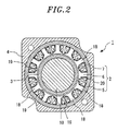
Fig. 2 is a cross sectional view taken along the line II-II inFig. 1 , showing the rotary electric machine provided with the bobbin according to the embodiment. -
Fig. 3 is an explanatory view showing one arrangement example of bobbins in the rotary electric machine according to the embodiment. -
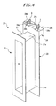
Fig. 4 is a perspective view of the bobbin according to the embodiment. -
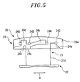
Fig. 5 is a plan view of the bobbin according to the embodiment. -
Fig. 6 is a front view of major portions of the bobbin according to the embodiment. -
Fig. 7 is a plan view of one bobbin wound with a coil wire, showing the bobbin according to the embodiment. -
Fig. 8 is a plan view of another bobbin wound with a coil wire, which is adjacent to the bobbin shown inFig. 7 , showing the bobbin according to an embodiment. -
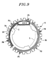
Fig. 9 is a plan view showing a front surface of a substrate in the rotary electric machine according to the embodiment. -
Fig. 10 is a plan view showing a rear surface of the substrate in the rotary electric machine according to the embodiment. -
Fig. 11 is a view for explaining an arrangement example of bobbins in a rotary electric machine according to a comparative example. -
Fig. 12 is a plan view showing a front surface of a substrate in the rotary electric machine according to the comparative example. -
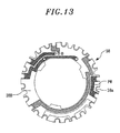
Fig. 13 is a plan view showing a rear surface of the substrate in the rotary electric machine according to the comparative example. -
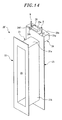
Fig. 14 is a perspective view of a bobbin according to a modified example of the embodiment, in which a substrate mounting protrusion is arranged on a terminal surface of a substrate mounting portion. -
Fig. 15 is a plan view of the bobbin according to the modified example. -
Fig. 16 is a plan view of one bobbin wound with a coil wire, showing the bobbin according to the modified example. -
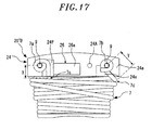
Fig. 17 is a plan view of another bobbin wound with a coil wire, which is adjacent to the bobbin shown inFig. 16 , showing the bobbin according to the modified example. -
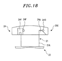
Fig. 18 is a plan view of one bobbin in a rotary electric machine according to another modified example in which two kinds of bobbins are used. -
Fig. 19 is a plan view of the bobbin wound with a coil wire, showing the bobbin shown inFig. 18 . - An embodiment will now be described in detail with reference to the accompanying drawings.
- First, the configuration of a rotary electric machine 1 in accordance with an embodiment will be described with reference to
Figs. 1 and2 . As shown inFig. 1 , the rotary electric machine 1 includes astator 2 and arotor 3. The rotary electric machine 1 is an inner-rotor-type motor in which therotor 3 is arranged inside thestator 2. The rotary electric machine 1 may be a generator. Thestator 2 is arranged on an inner circumferential surface of aframe 4 through a laminatedcore ring 5 to radially face therotor 3. - As shown in
Fig. 2 , thestator 2 includes a laminatedcore ring 5, a laminated core body 6 (a stator core), a plurality ofbobbins 20 mounted to the laminatedcore body 6 and a plurality ofcoil wires 7 wound on thebobbins 20. Thebobbins 20 are made of an insulating material (a resin or the like) in order to electrically insulate the laminatedcore body 6 from thecoil wires 7. A substrate 8 (a wire connection substrate) is arranged at one axial end (the left end inFig. 1 ) of thebobbins 20. - The circuit arranged in the
substrate 8 and thecoil wires 7 wound on thebobbins 20 are electrically connected to each other through two square-bar-shaped pin terminals 9. As shown inFig. 3 , a winding startingend portion 7a and a windingfinishing end portion 7b of each of thecoil wires 7 are wrapped around thecorresponding pin terminals 9 and are fixed by, e.g., solders (not shown). - The
rotor 3 is formed of a permanent magnet and is provided on an outer circumferential surface of ashaft 10. Theshaft 10 is rotatably supported by a load-side bearing 12 whose outer race is fitted to a load-side bracket 11 provided at the load side (the right side inFig. 1 ) of theframe 4 and a counter-load-side bearing 14 whose outer race is fitted to a counter-load-side bracket 13 provided at the counter-load side (the opposite side to the load side, i.e., the left side inFig. 1 ) of theframe 4. Anencoder 15 is provided at the counter-load-side end portion of theshaft 10. Theencoder 15 is covered with anencoder cover 16. - The laminated
core body 6 is provided with a plurality of (e.g., twelve inFig. 2 )radial projections 18 which protrude radially outward. Thebobbins 20 wound with thecoil wires 7 are mounted to therespective projections 18 from the radial outer side. As shown inFig. 2 , in each ofrecesses 19 between theadjacent projections 18, the side portions of thebobbins 20 mounted to therespective projections 18, at which the winding layers of thecoil wires 7 face each other, are disposed in a spaced-apart relationship with each other. - The
bobbins 6 wound with thecoil wires 7 are mounted to the laminatedcore body 6 and are then fixed to the inner circumferential surface of the laminatedcore ring 5 having an annular shape, thereby forming thestator 2. Thestator 2 thus formed is mounted to the inner circumferential surface of theframe 4. Thereafter, a resin is introduced into therecesses 19, whereby thebobbins 20 and thecoil wires 7 are molded with the resin. - In the present embodiment, the rotary electric machine 1 is a rotary induction motor using a three-phase alternating current. As shown in
Fig. 3 , slot combination in section of the rotary electric machine 1 includes ten poles and twelve slots (10P and 12S) in case of a permanent magnet synchronous motor. In this slot combination, as shown inFig. 3 , the bobbins 20 (namely, thebobbins - In
Fig. 3 , U, V and W designate thebobbins 20 corresponding to a U-phase, a V-phase and a W-phase. U, V and W designate thebobbins 20 differing 180 degrees in electrical angle from the bobbins U, V and W (This holds true inFig. 7 ). InFig. 3 , further, the relationship of the wire connection patterns of individual phases in thesubstrate 8 to be described below is indicated by double-dot chain lines or single-dot chain lines. - Next, the detailed structure of each of the
bobbins 20 will be described with reference toFigs. 4 to 8 . In the rotary electric machine 1, the bobbins 20 (twelvebobbins 20 in the present embodiment) mounted to thelaminated core body 6 has the same structure. As shown inFigs. 4 to 6 , each of thebobbins 20 includes a substantially quadrilateral frame-like trunk portion (a coil winding portion) 21 wound with thecoil wire 7, afirst flange portion 22 formed along the edge of one end of thetrunk portion 21, asecond flange portion 23 formed along the edge of the other end of thetrunk portion 21, and asubstrate mounting portion 24 installed in thesecond flange portion 23 to mount thereon thesubstrate 8 and provided with a terminal fixing portion for fixing the winding startingend portion 7a and the winding finishingend portion 7b of thecoil wire 7, which will be described later. - The
trunk portion 21 includescoil winding surfaces 21a opposite to each other in theaxial direction 10a of the stator 2 (the left-right direction inFig. 1 and the up-down direction inFig. 4 ) andcoil winding surfaces 21b opposite to each other in the circumferential direction of thestator 2. Thetrunk portion 21 is formed into a hollow prismatic shape and is provided with ahollow portion 25 into which theprojection 18 of thelaminated core body 6 is inserted. - The
first flange portion 22 is formed into a rectangular shape extending along the edge of the one end of thetrunk portion 21 to open one end of thehollow portion 25. Similarly, thesecond flange portion 23 is formed into a rectangular shape extending along the edge of the other end of thetrunk portion 21 to open the other end of thehollow portion 25. Thesecond flange portion 23 protrudes from thetrunk portion 21 to be larger in size than thefirst flange portion 22. - The
substrate mounting portion 24 is provided at one short side (the upper side inFig. 4 ) of thesecond flange portion 23. Twopin terminals 9 are inserted into thesubstrate mounting portion 24 to protrude from the upper surface of thesubstrate mounting portion 24. The winding startingend 7a and the winding finishingend 7b of thecoil wire 7 are respectively fixed to thepin terminals 9. In the following description, the surface of thesubstrate mounting portion 24 into which thepin terminals 9 are inserted will be referred to as a "terminal surface 24a". - Two kinds of coil winding methods are employed in the
bobbins 20 in accordance with the present embodiment. Specifically, in thebobbin 20A shown inFig. 7 , a winding starting section X from the winding startingend portion 7a of thecoil wire 7 to a windingstarting position 7c of thetrunk portion 21 and a winding finishing section Y from a windingfinishing position 7d of thetrunk portion 21 to the winding finishingend portion 7b of thecoil wire 7 intersect each other when seen in theaxial direction 10a. The bobbin that employs this coil winding method will be sometimes referred to as "bobbin 20A" (first bobbin) herein below. - In contrast, in the
bobbin 20B shown inFig. 8 , the winding starting section X extending from the winding startingend portion 7a of thecoil wire 7 to the winding startingposition 7c of thetrunk portion 21 and the winding finishing section Y extending from the windingfinishing position 7d of thetrunk portion 21 to the winding finishingend portion 7b do not intersect each other when seen in theaxial direction 10a. The bobbin that employs this coil winding method will be sometimes referred to as "bobbin 20B" (second bobbin) herein below. - The
terminal surface 24a of thesubstrate mounting portion 24 has a structure that enables the winding starting section X and the winding finishing section Y of thecoil wire 7 to easily intersect each other. Specifically, as shown inFigs. 4 to 6 , afirst groove 24b which guides the winding starting section X of thecoil wire 7 and asecond groove 24c which guides the winding finishing section Y of thecoil wire 7 to intersect the winding starting section X are provided in theterminal surface 24a of thesubstrate mounting portion 24. Athird groove 24d and afourth groove 24e, which respectively guide the winding starting section X and the winding finishing section Y of thecoil wire 7 not to intersect each other, are provided in theterminal surface 24a of thesubstrate mounting portion 24. - A
recess 24h deeper than thegrooves 24b to 24d is formed in an end portion of thethird groove 24d at the side of thetrunk portion 21. Therecess 24h guides the winding starting section X of thecoil wire 7 to the winding startingposition 7c of thetrunk portion 21. Particularly, as shown inFig. 7 , in thebobbin 20A in which the winding starting section X and the winding finishing section Y of thecoil wire 7 intersect each other when seen in theaxial direction 10a, thecoils 14 guided by thefirst groove 24b is fitted in therecess 24h. Thus, a height difference occurs between the winding starting section X and the winding finishing section Y of thecoil wire 7. This makes it possible to have the winding starting section X and the winding finishing section Y intersect each other while avoiding mutual interference of the winding starting section X and the winding finishing section Y. - Four
pin holes 24A to 24D, into which thepin terminals 9 are inserted, are formed in theterminal surface 24a of thesubstrate mounting portion 24. The twopin terminals 9 are selectively inserted into one of the pin holes 24A and 24C and one of the pin holes 24B and 24D, respectively. The pin holes 24A and 24C are spaced apart by a predetermined distance in the rotation direction of the rotor 3 (in the direction indicated by an arrow A inFig. 5 ). Similarly, the pin holes 24B and 24D are spaced apart by a predetermined distance in the rotation direction of the rotor 3 (in the direction indicated by the arrow A inFig. 5 ). - As shown in
Fig. 7 , in thebobbin 20A in which the winding starting section X and the winding finishing section Y of thecoil wire 7 intersect each other when seen in theaxial direction 10a, the pin terminal 9 (first pin) for winding the winding startingend portion 7a of thecoil wire 7 is inserted into thepin hole 24A (first pin hole), and the pin terminal 9 (second pin) for winding the winding finishingend portion 7b of thecoil wire 7 is inserted into thepin hole 24B (second pin hole). - On the other hand, as shown in
Fig. 8 , in thebobbin 20B in which the winding starting section X and the winding finishing section Y of thecoil wire 7 do not intersect each other when seen in theaxial direction 10a, the pin terminal 9 (first pin) for winding the winding startingend portion 7a of thecoil wire 7 is inserted into thepin hole 24D (first pin hole), and the pin terminal 9 (second pin) for winding the winding finishingend portion 7b of thecoil wire 7 is inserted into thepin hole 24C (second pin hole). The insertion positions of thepin terminals 9 shown inFig. 4 correspond to thebobbin 20B. - In the rotary electric machine 1, as shown in
Fig. 3 , thebobbin 20A and thebobbin 20B are alternately arranged to adjoin each other in the circumferential direction. Specifically, with respect to the U-phase, the V-phase and the W-phase, thebobbins end portion 7a and the winding finishingend portion 7b of thecoil wire 7 in thebobbin 20A are opposite to those in thebobbin 20B along the rotation direction. Therefore, if thebobbin 20A and thebobbin 20B are disposed adjacent to each other, the winding finishingend portions 7b of thecoil wires 7 can adjoin each other in each of the phases. - Circuit patterns for connecting the
coil wires 7 of therespective bobbins 20 in a predetermined pattern (in a wire connection pattern shown inFig. 3 ) are formed in thesubstrate 8.Fig. 9 shows a circuit pattern formed on afront surface 8A of thesubstrate 8.Fig. 10 shows a circuit pattern formed on arear surface 8B of thesubstrate 8. InFigs. 9 and10 , reference symbols PU, PV and PW designate wire connection patterns for connecting the winding finishingend portions 7b of thecoil wires 7 of theadjacent bobbins holes 8a. - The present embodiment will be described using a comparative example shown in
Figs. 11 to 13 . As shown inFig. 11 , in a rotaryelectric machine 1A in accordance with a comparative example, each ofbobbins 30 is configured such that, as in thebobbin 20B of the aforementioned embodiment, the winding starting section X and the winding finishing section Y of thecoil wire 7 do not intersect each other when seen in theaxial direction 10a. Further, therespective bobbins 30 employ the same coil winding method. For that reason, the positions of the winding startingend portions 7a and the winding finishingend portions 7b of thecoil wires 7 in therespective bobbins 30 are in the same positional relationship along the rotation direction. As a result, the degree of freedom in arranging the wire connection patterns in thesubstrate 8 becomes lower, and the wire connection patterns grow complex. - More specifically, as shown in
Fig. 11 , in the rotaryelectric machine 1A, the winding startingend portions 37a and the winding finishingend portions 37b of therespective bobbins 30 are alternately positioned along the circumferential direction. As a result, as shown inFigs. 12 and13 , in thesubstrate 38 of the rotaryelectric machine 1A in accordance with the comparative example, each of the wire connection patterns PU, PV and PW for interconnecting the winding startingend portions 7a or the winding finishingend portions 7b of thecoil wires 7 of theadjacent bobbins 30 in each of the U-phase, the V-phase and the W-phase becomes a wire connection pattern in which other through-hole(s) 38a is interposed between the winding startingend portions 7a or between the winding finishingend portions 7b by detouring the corresponding through-hole(s) 38a. This makes the circuit patterns complex and makes it necessary to increase a width spanning from the inner periphery of thesubstrate 38 to the outer periphery thereof. As a result, this leads to an increase in the size of the rotaryelectric machine 1A. - In the rotary electric machine 1 according to the present embodiment, as described above, there are employed two kinds of
bobbins end portions 7a and the winding finishingend portions 7b of thecoil wires 7 in thebobbins 20A are opposite to those in thebobbins 20B along the rotation direction. It is therefore possible to form the circuit patterns of thesubstrate 8 into predetermined wire connection patterns by appropriately disposing thebobbins end portions 7a and the positions of the winding finishingend portions 7b). This makes it possible to increase the degree of freedom in arranging the wire connection patterns in thesubstrate 8. As a result, it becomes possible to simplify the circuit patterns of thesubstrate 8. - Specifically, as shown in
Figs. 9 and10 , the respective wire connection patterns PU, PV and PW are formed by interconnecting the adjacent through-holes 8a. This makes it possible to simplify the overall circuit patterns of thesubstrate 8. - As a result of the simplification of the circuit patterns of the
substrate 8, it becomes possible, as in the present embodiment, to make thesubstrate 8 as a double-side substrate in which circuit patterns are formed on the opposite surfaces thereof. Therefore, as compared with a case where thesubstrate 8 is made from a multi-layer substrate, it is possible to reduce the size of the rotary electric machine 1 and to save the costs. Further, as a result of the simplification of the circuit patterns, it is possible to reduce the arrangement area of the circuit patterns. This makes it possible to increase the space in thesubstrate 8 in which a resin for molding thebobbins 20 flows. For example, in thesubstrate 8 shown inFigs. 9 and10 , as compared with thesubstrate 38 of the comparative example shown inFigs. 12 and13 , it is possible to increase the opening area just as much as the space S. Thus, a resin is easy to flow, which makes it possible to reduce generation of molding defects. - In the present embodiment, the
first groove 24b and thesecond groove 24c are formed in theterminal surface 24a of thesubstrate mounting portion 24. Thefirst groove 24b guides the winding starting section X of thecoil wire 7 of thebobbin 20A. Thesecond groove 24c guides the winding finishing section Y of thecoil wire 7 of thebobbin 20A. By guiding the winding starting section X and the winding finishing section Y of thecoil wire 7 with therespective grooves axial direction 10a. - Further, by allowing the winding starting section X and the winding finishing section Y to pass through the
respective grooves coil wire 7 and to enhance the durability of thecoil wire 7. By forming therespective grooves grooves coil wire 7. Thus, thesubstrate 8 can be mounted on theterminal surface 24a of thesubstrate mounting portion 24. - In the present embodiment, the
third groove 24d and thefourth groove 24e are additionally formed on theterminal surface 24a of thesubstrate mounting portion 24. Thus, in thebobbin 20A, thecoil wire 7 can be wound using thefirst groove 24b and thesecond groove 24c such that the winding starting section X and the winding finishing section Y intersect each other when seen in theaxial direction 10a. In thebobbin 20B, thecoil wire 7 can be wound using thethird groove 24d and thefourth groove 24e such that the winding starting section X and the winding finishing section Y do not intersect each other when seen in theaxial direction 10a. - Accordingly, it is possible to, using the bobbins of the same shape, provide two kinds of bobbins, namely the
bobbin 20A in which the winding starting section X and the winding finishing section Y intersect each other when seen in theaxial direction 10a and thebobbin 20B in which the winding starting section X and the winding finishing section Y do not intersect each other when seen in theaxial direction 10a. For that reason, the bobbins can be manufactured by one kind of mold. Therefore, as compared with a case where the bobbins are manufactured by two kinds of molds, it is possible to save the costs. Since thebobbins 20 of one kind are used, management of thebobbins 20 becomes easier. - In the present embodiment, at least two pin holes are provided on the
terminal surface 24a of thesubstrate mounting portion 24. For example, in thebobbin 20A, the winding startingend portion 7a of thecoil wire 7 is wrapped around thepin terminal 9 as the first pin inserted into thepin hole 24A. The winding finishingend portion 7b of thecoil wire 7 is wrapped around thepin terminal 9 as the second pin inserted into thepin hole 24B. By wrapping the winding startingend portion 7a and the winding finishingend portion 7b of thecoil wire 7 around thepin terminals 9 in this manner, it is possible to firmly fix the winding startingend portion 7a and the winding finishingend portion 7b through the use of a solder or the like. Use of the pins as connecting terminals makes it possible to connect the winding startingend portion 7a and the winding finishingend portion 7b of thecoil wire 7 to thesubstrate 8 in an electrically stable manner. - In the present embodiment, four
pin holes 24A to 24D are provided on theterminal surface 24a of thesubstrate mounting portion 24. Twopin holes end portion 7a of thecoil wire 7 in thebobbin 20A (the position of the winding finishingend portion 7b in thebobbin 20B) can be selected by inserting thepin terminal 9 into one of the pin holes 24A and 24C. Since the other second pin holes 24B and 24D are similarly arranged, it is possible to select the position of the winding finishingend portion 7b in thebobbin 20A (the position of the winding startingend portion 7a in thebobbin 20B). - As a result, in case where the
bobbins 20 wound with the coils of the same phase are disposed adjacent to each other to provide a wire connection pattern in which the winding finishingend portions 7b of theadjacent coil wires 7 are connected to each other as in the rotary electric machine 1 of the present embodiment, thepin hole 24B is selected in thebobbin 20A and thepin hole 24C is selected in thebobbin 20B such that the winding finishingend portions 7b of thecoil wires 7 are positioned closer to each other. Thus, it is possible to make shortest the wire connection patterns PU, PV and PW for interconnecting the winding finishingend portions 7b. This makes it possible to simplify the circuit patterns. - Further, in case where the
bobbins 20 wound with the coils of different phases are disposed adjacent to each other as in the rotary electric machine 1 of the present embodiment, thepin hole 24A is selected for the winding startingend portion 7a of thecoil wire 7 in thebobbin 20A and thepin hole 24D is selected for the winding startingend portion 7a of thecoil wire 7 in thebobbin 20B such that the winding starting ends 7a of theadjacent coil wires 7 are positioned farther from each other. - Thus, it is possible to secure a distance for the insulation between the winding starting
end portions 7a of the coils of different phases. By disposing the winding startingend portions 7a of thecoil wires 7 farther from each other in this manner, a space (agroove 8b shown inFigs. 9 and10 ) in which a resin for molding the coils flows can be formed in the corresponding position of thesubstrate 8. This makes it possible to reduce the influence of the pressure of the resin on the winding startingend portions 7a. - By forming a pair of pin holes with respect to each of the winding starting
end portion 7a and the winding finishingend portion 7b of thecoil wire 7, it is possible to make different the relative positions of thepin terminals 9 corresponding to the winding startingend portions 7a and the winding finishingend portions 7b in thebobbins 20 disposed adjacent to each other. Therefore, if thebobbins 20 are erroneously disposed (for example, if thebobbins 20A or thebobbins 20B are disposed adjacent to each other), thepin terminals 9 interfere with thesubstrate 8 without passing through the corresponding through-holes 8a of thesubstrate 8 during the course of mounting thesubstrate 8. This provides an effect in that an erroneously disposedbobbin 20 can be identified. - Further, in the present embodiment, the rotary electric machine 1 is configured to have a slot combination of ten poles and twelve slots (10P-12S). In this case, there can be provided a wire connection pattern in which the winding starting
end portions 7a or the winding finishingend portions 7b of thecoil wires 7 are connected to each other. Therefore, the bobbin configuration according to the present embodiment is particularly useful. - The present disclosure is not limited to the embodiment described above but may be differently modified without departing from the sprit and scope of the present disclosure. Various modified examples will now be described.
- In the aforementioned embodiment, the
substrate 8 is mounted to theterminal surface 24a of thesubstrate mounting portion 24. Alternatively, a substrate mounting protrusion may be formed on theterminal surface 24a and a gap may be provided between theterminal surface 24a and thesubstrate 8. The present modified example will be described with reference toFigs. 14 to 17 . - As shown in
Figs. 14 and15 , the bobbin 20' of the present modified example includes a substantiallyrectangular parallelepiped protrusion 26 arranged on theterminal surface 24a of thesubstrate mounting portion 24. Theprotrusion 26 has a mountingsurface 26a to which thesubstrate 8 is mounted. Thus, a gap is formed between theterminal surface 24a and thesubstrate 8 mounted to the mountingsurface 26a of theprotrusion 26. The gap can be used to wrap the end portion of thecoil wire 7. In the present modified example, unlike the aforementioned embodiment, instead of thefirst groove 24b and thesecond groove 24c intersecting each other when seen in theaxial direction 10a,grooves - The
groove 24f is a groove that guides the winding starting section X or the winding finishing section Y of thecoil wire 7. Thegroove 24g is a groove that guides the winding finishing section Y of thecoil wire 7. In the present modified example, threepin holes pin terminals 9 are formed on theterminal surface 24a, and thepin hole 24D is not formed. Other configurations of the bobbin 20' in accordance with the present modified example are the same as the configurations of thebobbin 20 of the aforementioned embodiment and, therefore, will not be described herein. -
Fig. 16 shows a bobbin 20'A in which the winding starting section X and the winding finishing section Y of thecoil wire 7 intersect each other when seen in the axial direction. In the bobbin 20'A, the pin terminal 9 (the first pin) around which the winding startingend portion 7a of thecoil wire 7 is wrapped is inserted into thepin hole 24A (the first pin hole). The pin terminal 9 (the second pin) around which the winding finishingend portion 7b of thecoil wire 7 is wrapped is inserted into thepin hole 24B (the second pin hole). The winding starting section X of thecoil wire 7 is drawn to thegroove 24f around theprotrusion 26 and is guided to the winding startingposition 7c of thetrunk portion 21 by thegrooves - The winding finishing section Y of the
coil wire 7 is a section extending from the windingfinishing position 7d of thetrunk portion 21 corresponding to one corner of theprotrusion 26 to the winding finishingend portion 7b. As in the aforementioned embodiment, therecess 24h enables the winding starting section X and the winding finishing section Y to intersect each other while avoiding mutual interference. The insertion positions of thepin terminals 9 shown inFig. 14 correspond to the bobbin 20'A. - On the other hand,
Fig. 17 shows a bobbin 20'B in which the winding starting section X and the winding finishing section Y of thecoil wire 7 do not intersect each other when seen in the axial direction. In the bobbin 20'B, the pin terminal 9 (the first pin) around which the winding startingend portion 7a of thecoil wire 7 is wrapped is inserted into thepin hole 24B (the first pin hole). The pin terminal 9 (the second pin) around which the winding finishingend portion 7b of thecoil wire 7 is wrapped is inserted into thepin hole 24C (the second pin hole). - According to the modified example described above, the bobbins 20'A and 20'B employing two kinds of coil winding methods can be provided using one kind of bobbin 20'. It is therefore possible to obtain the same effects as available in the aforementioned embodiment. The installation of the
protrusion 26 eliminates the need to form thefirst groove 24b and thesecond groove 24c intersecting each other when seen in theaxial direction 10a, which are employed in the aforementioned embodiment. This makes it possible to simplify the configuration of the bobbins. - In the aforementioned embodiment, the
bobbins common bobbins 20. However, since thebobbin 20B is configured such that the winding starting section X and the winding finishing section Y of thecoil wire 7 do not intersect each other when seen in theaxial direction 10a, it may be possible to use, e.g., a bobbin 20C having a structure shown inFig. 18 instead of thebobbin 20B. The bobbin 20C includes twogrooves pin holes Fig. 19 , the winding starting section X of thecoil wire 7 is guided by thegroove 24f while the winding finishing section Y is guided by thegroove 24g. Thus, the winding starting section X and the winding finishing section Y of thecoil wire 7 can be configured not to intersect each other when seen in theaxial direction 10a. - In the embodiment and the modified examples described above, description has been made on a case where the present disclosure is applied to the rotary electric machine having the slot combination of ten poles and 12 slots (10P-12S). However, it may be possible to employ other slot combinations in which coils having the same phase but differing 180 degrees in electrical angle from each other are disposed adjacent to each other. For example, the present disclosure may be effectively applied to a rotary electric machine of eight poles and nine slots (8P-9S), a rotary electric machine of ten poles and nine slots (10P-9S) or a rotary electric machine of fourteen poles and twelve slots (14P-12S).
- While the foregoing description has been made by taking, as an example, a case where the rotary electric machine 1 is an inner-rotor-type rotary electric machine having the
rotor 3 arranged inside thestator 2, the present disclosure may be applied to an outer-rotor-type rotary electric machine having therotor 3 arranged outside thestator 2. While the foregoing description has been made by taking, as an example, a case where the bobbin of the present embodiment is used in thestator 2 of the rotary electric machine 1, the bobbin may be applied to therotor 3. - In addition to the above, the embodiment and the respective modified embodiments may be appropriately combined.
- While not specifically mentioned one by one, the present embodiment may be changed in many different forms without departing from the spirit thereof.
- It should be understood by those skilled in the art that various modifications, combinations, sub-combinations and alterations may occur depending on design requirements and other factors insofar as they are within the scope of the appended claims or the equivalents thereof.
Claims (8)
- A bobbin adapted to be mounted to a stator core of a rotary electric machine and configured to electrically insulate the stator core from a coil wire to be wound around the bobbin, the bobbin comprising:a coil winding portion around which the coil wire is to be wound; anda terminal fixing portion to which a winding starting end portion and a winding finishing end portion of the coil wire are to be fixed,wherein the terminal fixing portion includes a first groove configured to guide a winding starting section extending from the winding starting end portion of the coil wire to a winding starting position of the coil winding portion and a second groove configured to guide a winding finishing section extending from a winding finishing position of the coil winding portion to the winding finishing end portion of the coil wire to intersect the winding starting section when seen in an axial direction.
- The bobbin of claim 1, wherein the terminal fixing portion includes a third groove configured to guide the winding starting section and a fourth groove configured to guide the winding finishing section not to intersect the winding starting section when seen in the axial direction.
- The bobbin of claim 1 or 2, wherein the terminal fixing portion includes at least two pin holes into which a first pin for wrapping the winding starting end portion of the coil wire and a second pin for wrapping the winding finishing end portion of the coil wire are inserted.
- The bobbin of claim 3, wherein the terminal fixing portion includes two first pin holes spaced apart from each other by a predetermined distance in a rotation direction, and two second pin holes spaced apart from each other by a predetermined distance in the rotation direction, the first pin is inserted into one of the first pin holes while the second pin is inserted into one of the second pin holes.
- A rotary electric machine comprising:a bobbin body including the bobbin of any one of claims 1 to 4 around which a coil wire is wound such that a winding starting section of the coil wire intersects a winding finishing section of the coil wire when seen in the axial direction.
- The machine of claim 5, further comprising:a stator having the stator core;a rotor; anda wire connection substrate disposed at one axial end of the bobbin and provided with a wire connection pattern for connecting the coil wire in a predetermined wire connection pattern.
- The machine of claim 6, further comprising:an additional bobbin body formed by winding an additional coil wire around an additional bobbin,wherein the additional bobbin includes an additional coil winding portion around which the additional coil wire is wound and an additional terminal fixing portion to which a winding starting end portion and a winding finishing end portion of the additional coil wire are fixed,the additional bobbin body is configured such that, when seen in an axial direction, a winding starting section extending from the winding starting end portion of the additional coil wire wound around the additional bobbin to a winding starting position of the additional coil winding portion does not intersect a winding finishing section extending from a winding finishing position of the additional coil winding portion to the winding finishing end portion of the additional coil wire, andthe bobbin and the additional bobbin are disposed adjacent to each other in a circumferential direction of the stator.
- The machine of claim 6 or 7, which has a slot combination in which coils having the same phase but differing 180 degrees in electrical angle from each other are disposed adjacent to each other.
Applications Claiming Priority (1)
| Application Number | Priority Date | Filing Date | Title |
|---|---|---|---|
| JP2013105636A JP5858245B2 (en) | 2013-05-17 | 2013-05-17 | Bobbins and rotating electrical machines |
Publications (2)
| Publication Number | Publication Date |
|---|---|
| EP2804294A2 true EP2804294A2 (en) | 2014-11-19 |
| EP2804294A3 EP2804294A3 (en) | 2016-07-20 |
Family
ID=50238274
Family Applications (1)
| Application Number | Title | Priority Date | Filing Date |
|---|---|---|---|
| EP14158782.4A Withdrawn EP2804294A3 (en) | 2013-05-17 | 2014-03-11 | Bobbin and rotary electric machine comprising such a bobbin |
Country Status (6)
| Country | Link |
|---|---|
| US (1) | US9748813B2 (en) |
| EP (1) | EP2804294A3 (en) |
| JP (1) | JP5858245B2 (en) |
| KR (1) | KR101606262B1 (en) |
| CN (1) | CN104167847B (en) |
| BR (1) | BR102014006570A2 (en) |
Cited By (1)
| Publication number | Priority date | Publication date | Assignee | Title |
|---|---|---|---|---|
| FR3094585A1 (en) * | 2019-03-25 | 2020-10-02 | Valeo Japan Co. Ltd. | Insulating element of the coil head of a rotating electric machine stator, corresponding stator and rotating electric machine. |
Families Citing this family (12)
| Publication number | Priority date | Publication date | Assignee | Title |
|---|---|---|---|---|
| US9480415B2 (en) | 2013-04-26 | 2016-11-01 | Medtronic Navigation, Inc. | Electromagnetic coil apparatuses for surgical navigation and corresponding methods |
| US11096605B2 (en) * | 2015-03-31 | 2021-08-24 | Medtronic Navigation, Inc. | Modular coil assembly |
| TW201707351A (en) * | 2015-08-13 | 2017-02-16 | 建準電機工業股份有限公司 | Coil winding set and winding socket thereof whereby the outlet part of coils can be positioned in wire slots for subsequent connection with circuit boards |
| JP6304175B2 (en) * | 2015-08-19 | 2018-04-04 | 株式会社デンソー | Electric motor |
| JP6831615B2 (en) * | 2016-07-28 | 2021-02-17 | 三星電子株式会社Samsung Electronics Co.,Ltd. | Stator and brushless motor |
| CN110034640B (en) * | 2018-01-12 | 2020-07-28 | 日本电产三协电子(东莞)有限公司 | Manufacturing method of motor |
| CN110880823A (en) * | 2018-09-05 | 2020-03-13 | 光宝电子(广州)有限公司 | Insulating sleeve, stator unit structure and servo motor structure using same |
| JP7620505B2 (en) * | 2021-06-15 | 2025-01-23 | 株式会社ミツバ | Insulator, stator and electric motor |
| WO2022269672A1 (en) * | 2021-06-21 | 2022-12-29 | 住友電気工業株式会社 | Motor and wiring member |
| FR3127656B1 (en) * | 2021-09-30 | 2023-09-29 | Valeo Systemes Dessuyage | Coil for electric motor stator, associated stator and associated manufacturing method |
| GB2619413B8 (en) * | 2023-05-18 | 2024-11-20 | High Tech Battery Inc | Axial flux machine and stator for axial flux machine |
| WO2025046972A1 (en) | 2023-08-31 | 2025-03-06 | 株式会社安川電機 | Motor and motor manufacturing method |
Citations (1)
| Publication number | Priority date | Publication date | Assignee | Title |
|---|---|---|---|---|
| JPH09308142A (en) | 1996-05-20 | 1997-11-28 | Yaskawa Electric Corp | Rotating electric machine |
Family Cites Families (16)
| Publication number | Priority date | Publication date | Assignee | Title |
|---|---|---|---|---|
| JPH09219964A (en) * | 1996-02-13 | 1997-08-19 | Yaskawa Electric Corp | Brushless motor and winding method thereof |
| JP3478744B2 (en) * | 1998-11-27 | 2003-12-15 | 松下エコシステムズ株式会社 | Motor stator |
| JP3664608B2 (en) * | 1999-05-25 | 2005-06-29 | 三菱電機株式会社 | Rotating electric machine |
| US6856055B2 (en) * | 2002-07-11 | 2005-02-15 | Emerson Electric Co. | Interconnecting ring and wire guide |
| JP4112535B2 (en) * | 2004-07-30 | 2008-07-02 | 株式会社一宮電機 | Stator and brushless motor |
| JP4931449B2 (en) | 2006-03-22 | 2012-05-16 | 日本電産サンキョー株式会社 | motor |
| JP2008263691A (en) * | 2007-04-11 | 2008-10-30 | Minebea Co Ltd | Small diameter stepping motor, its bobbin, and assembly method of motor |
| JP4962127B2 (en) * | 2007-05-02 | 2012-06-27 | 住友電気工業株式会社 | Insulator |
| RU2352048C1 (en) * | 2007-08-08 | 2009-04-10 | Закрытое акционерное общество "ИРИС" | Valve reactive inductor motor |
| JP5237049B2 (en) * | 2008-10-28 | 2013-07-17 | アスモ株式会社 | Insulator, stator and stator manufacturing method |
| JP5478117B2 (en) * | 2009-05-21 | 2014-04-23 | アスモ株式会社 | motor |
| DE102010004887A1 (en) * | 2010-01-18 | 2011-07-21 | Tyco Electronics Belgium Ec Bvba | Spool for mounting on a magnetic core, magnetic core for reluctance resolver and method of manufacture |
| US8736129B2 (en) * | 2010-10-21 | 2014-05-27 | Emerson Electric Co. | End caps for stator segments of segmented stator assemblies |
| JP2012105372A (en) * | 2010-11-05 | 2012-05-31 | Honda Motor Co Ltd | Outer rotor type electric motor |
| JP5267541B2 (en) * | 2010-11-11 | 2013-08-21 | 株式会社安川電機 | Bobbins and rotating electrical machines |
| JP5418484B2 (en) * | 2010-12-08 | 2014-02-19 | 三菱電機株式会社 | Coil bobbin of stator of rotating electric machine and winding method of stator of rotating electric machine using this coil bobbin |
-
2013
- 2013-05-17 JP JP2013105636A patent/JP5858245B2/en active Active
-
2014
- 2014-03-11 EP EP14158782.4A patent/EP2804294A3/en not_active Withdrawn
- 2014-03-17 KR KR1020140031119A patent/KR101606262B1/en active Active
- 2014-03-19 CN CN201410102471.3A patent/CN104167847B/en active Active
- 2014-03-19 BR BRBR102014006570-9A patent/BR102014006570A2/en not_active IP Right Cessation
- 2014-03-20 US US14/220,135 patent/US9748813B2/en active Active
Patent Citations (1)
| Publication number | Priority date | Publication date | Assignee | Title |
|---|---|---|---|---|
| JPH09308142A (en) | 1996-05-20 | 1997-11-28 | Yaskawa Electric Corp | Rotating electric machine |
Cited By (2)
| Publication number | Priority date | Publication date | Assignee | Title |
|---|---|---|---|---|
| FR3094585A1 (en) * | 2019-03-25 | 2020-10-02 | Valeo Japan Co. Ltd. | Insulating element of the coil head of a rotating electric machine stator, corresponding stator and rotating electric machine. |
| EP3949085A4 (en) * | 2019-03-25 | 2023-06-07 | Valeo Japan Co., Ltd. | INSULATION ELEMENT FOR COIL HEADS OF A STATOR OF A ROTATING ELECTRIC MACHINE, AND CORRESPONDING STATOR AND ROTATING ELECTRIC MACHINE |
Also Published As
| Publication number | Publication date |
|---|---|
| CN104167847B (en) | 2017-05-17 |
| US20140339935A1 (en) | 2014-11-20 |
| KR20140135913A (en) | 2014-11-27 |
| US9748813B2 (en) | 2017-08-29 |
| JP5858245B2 (en) | 2016-02-10 |
| CN104167847A (en) | 2014-11-26 |
| EP2804294A3 (en) | 2016-07-20 |
| KR101606262B1 (en) | 2016-03-24 |
| JP2014230305A (en) | 2014-12-08 |
| BR102014006570A2 (en) | 2015-06-02 |
Similar Documents
| Publication | Publication Date | Title |
|---|---|---|
| US9748813B2 (en) | Bobbin and rotary electric machine | |
| US8610328B2 (en) | Rotary electric machine | |
| EP2273654B1 (en) | Rotating electric machine and manufacturing method thereof | |
| US10536046B2 (en) | Rotary electric machine with stator having bus bars with recesses and bus bar holder with protrusions engaged with the recesses | |
| JP6033582B2 (en) | Stator and stator manufacturing method | |
| CN103548244B (en) | Electric rotating machine and manufacture method thereof | |
| EP2833520B1 (en) | Stator | |
| JP2004229459A (en) | Centralized winding stator coil for rotating electric machine | |
| KR20080021678A (en) | Armature of rotary motor, rotary motor and manufacturing method thereof | |
| WO2019004116A1 (en) | Stator, motor, and stator manufacturing method | |
| EP2031735B1 (en) | Stator and electric motor | |
| JP5998871B2 (en) | Rotating electric machine stator | |
| JP5111887B2 (en) | Rotating electric machine stator | |
| JP2019103354A (en) | Rotary electric machine | |
| KR20220007448A (en) | Bus bar unit for motor | |
| CN203722367U (en) | Rotating electromotor | |
| JP7019452B2 (en) | Stator and rotary machine | |
| WO2018168108A1 (en) | Rotating electric machine | |
| JP6488100B2 (en) | Electric motor | |
| JP2019103298A (en) | Rotating electrical machine | |
| CN110710085A (en) | Stator and Motor | |
| JP2020150715A (en) | Armature |
Legal Events
| Date | Code | Title | Description |
|---|---|---|---|
| PUAI | Public reference made under article 153(3) epc to a published international application that has entered the european phase |
Free format text: ORIGINAL CODE: 0009012 |
|
| 17P | Request for examination filed |
Effective date: 20140311 |
|
| AK | Designated contracting states |
Kind code of ref document: A2 Designated state(s): AL AT BE BG CH CY CZ DE DK EE ES FI FR GB GR HR HU IE IS IT LI LT LU LV MC MK MT NL NO PL PT RO RS SE SI SK SM TR |
|
| AX | Request for extension of the european patent |
Extension state: BA ME |
|
| PUAL | Search report despatched |
Free format text: ORIGINAL CODE: 0009013 |
|
| AK | Designated contracting states |
Kind code of ref document: A3 Designated state(s): AL AT BE BG CH CY CZ DE DK EE ES FI FR GB GR HR HU IE IS IT LI LT LU LV MC MK MT NL NO PL PT RO RS SE SI SK SM TR |
|
| AX | Request for extension of the european patent |
Extension state: BA ME |
|
| RIC1 | Information provided on ipc code assigned before grant |
Ipc: H02K 1/14 20060101ALN20160610BHEP Ipc: H02K 3/34 20060101AFI20160610BHEP |
|
| STAA | Information on the status of an ep patent application or granted ep patent |
Free format text: STATUS: THE APPLICATION IS DEEMED TO BE WITHDRAWN |
|
| 18D | Application deemed to be withdrawn |
Effective date: 20170121 |