EP2804032A1 - Quick-shutter optical device - Google Patents
Quick-shutter optical device Download PDFInfo
- Publication number
- EP2804032A1 EP2804032A1 EP20140167311 EP14167311A EP2804032A1 EP 2804032 A1 EP2804032 A1 EP 2804032A1 EP 20140167311 EP20140167311 EP 20140167311 EP 14167311 A EP14167311 A EP 14167311A EP 2804032 A1 EP2804032 A1 EP 2804032A1
- Authority
- EP
- European Patent Office
- Prior art keywords
- fabry
- spacing
- perot
- nominal
- gap
- Prior art date
- Legal status (The legal status is an assumption and is not a legal conclusion. Google has not performed a legal analysis and makes no representation as to the accuracy of the status listed.)
- Withdrawn
Links
- 230000003287 optical effect Effects 0.000 title claims description 28
- 230000005855 radiation Effects 0.000 claims abstract description 16
- 230000000737 periodic effect Effects 0.000 claims abstract description 14
- 210000001747 pupil Anatomy 0.000 claims description 9
- 238000000034 method Methods 0.000 claims description 2
- 230000005540 biological transmission Effects 0.000 description 13
- 230000010287 polarization Effects 0.000 description 5
- 241000287107 Passer Species 0.000 description 2
- 238000001514 detection method Methods 0.000 description 2
- 230000005284 excitation Effects 0.000 description 2
- 230000000712 assembly Effects 0.000 description 1
- 238000000429 assembly Methods 0.000 description 1
- 230000007123 defense Effects 0.000 description 1
- 238000005286 illumination Methods 0.000 description 1
- 230000010358 mechanical oscillation Effects 0.000 description 1
Images


Classifications
-
- G—PHYSICS
- G01—MEASURING; TESTING
- G01J—MEASUREMENT OF INTENSITY, VELOCITY, SPECTRAL CONTENT, POLARISATION, PHASE OR PULSE CHARACTERISTICS OF INFRARED, VISIBLE OR ULTRAVIOLET LIGHT; COLORIMETRY; RADIATION PYROMETRY
- G01J3/00—Spectrometry; Spectrophotometry; Monochromators; Measuring colours
- G01J3/02—Details
- G01J3/0205—Optical elements not provided otherwise, e.g. optical manifolds, diffusers, windows
- G01J3/0232—Optical elements not provided otherwise, e.g. optical manifolds, diffusers, windows using shutters
-
- H—ELECTRICITY
- H04—ELECTRIC COMMUNICATION TECHNIQUE
- H04N—PICTORIAL COMMUNICATION, e.g. TELEVISION
- H04N23/00—Cameras or camera modules comprising electronic image sensors; Control thereof
- H04N23/70—Circuitry for compensating brightness variation in the scene
- H04N23/73—Circuitry for compensating brightness variation in the scene by influencing the exposure time
-
- G—PHYSICS
- G01—MEASURING; TESTING
- G01J—MEASUREMENT OF INTENSITY, VELOCITY, SPECTRAL CONTENT, POLARISATION, PHASE OR PULSE CHARACTERISTICS OF INFRARED, VISIBLE OR ULTRAVIOLET LIGHT; COLORIMETRY; RADIATION PYROMETRY
- G01J3/00—Spectrometry; Spectrophotometry; Monochromators; Measuring colours
- G01J3/12—Generating the spectrum; Monochromators
- G01J3/26—Generating the spectrum; Monochromators using multiple reflection, e.g. Fabry-Perot interferometer, variable interference filters
-
- G—PHYSICS
- G02—OPTICS
- G02B—OPTICAL ELEMENTS, SYSTEMS OR APPARATUS
- G02B26/00—Optical devices or arrangements for the control of light using movable or deformable optical elements
- G02B26/001—Optical devices or arrangements for the control of light using movable or deformable optical elements based on interference in an adjustable optical cavity
-
- G—PHYSICS
- G02—OPTICS
- G02B—OPTICAL ELEMENTS, SYSTEMS OR APPARATUS
- G02B26/00—Optical devices or arrangements for the control of light using movable or deformable optical elements
- G02B26/02—Optical devices or arrangements for the control of light using movable or deformable optical elements for controlling the intensity of light
-
- G—PHYSICS
- G02—OPTICS
- G02B—OPTICAL ELEMENTS, SYSTEMS OR APPARATUS
- G02B5/00—Optical elements other than lenses
- G02B5/20—Filters
- G02B5/28—Interference filters
- G02B5/284—Interference filters of etalon type comprising a resonant cavity other than a thin solid film, e.g. gas, air, solid plates
-
- H—ELECTRICITY
- H04—ELECTRIC COMMUNICATION TECHNIQUE
- H04N—PICTORIAL COMMUNICATION, e.g. TELEVISION
- H04N23/00—Cameras or camera modules comprising electronic image sensors; Control thereof
- H04N23/56—Cameras or camera modules comprising electronic image sensors; Control thereof provided with illuminating means
-
- H—ELECTRICITY
- H04—ELECTRIC COMMUNICATION TECHNIQUE
- H04N—PICTORIAL COMMUNICATION, e.g. TELEVISION
- H04N23/00—Cameras or camera modules comprising electronic image sensors; Control thereof
- H04N23/70—Circuitry for compensating brightness variation in the scene
- H04N23/74—Circuitry for compensating brightness variation in the scene by influencing the scene brightness using illuminating means
-
- H—ELECTRICITY
- H04—ELECTRIC COMMUNICATION TECHNIQUE
- H04N—PICTORIAL COMMUNICATION, e.g. TELEVISION
- H04N23/00—Cameras or camera modules comprising electronic image sensors; Control thereof
- H04N23/50—Constructional details
- H04N23/55—Optical parts specially adapted for electronic image sensors; Mounting thereof
-
- H—ELECTRICITY
- H04—ELECTRIC COMMUNICATION TECHNIQUE
- H04N—PICTORIAL COMMUNICATION, e.g. TELEVISION
- H04N23/00—Cameras or camera modules comprising electronic image sensors; Control thereof
- H04N23/70—Circuitry for compensating brightness variation in the scene
- H04N23/75—Circuitry for compensating brightness variation in the scene by influencing optical camera components
Definitions
- the present invention relates to an optical fast shutter device. It also relates to an active observation system comprising such an optical quick shutter device, in particular for defense and security applications.
- an active observation system is configured to illuminate a scene of the environment using a laser source, in order to improve the quality of an image of said scene and / or to highlight some specific details, such as pointed optics for example.
- said observation system comprises a laser source with a specific beam shape generation optics and a reception camera capable of producing an image of the illuminated scene.
- a feature of an active system as considered is its ability to illuminate only a restricted portion of the space. To do this, the camera is sensitive to incoming light for a very short time, typically between 0.1 ⁇ s and 10 ⁇ s. If the laser illumination also uses a short pulse, the combination with the short exposure time of the camera results in a selection of photons which correspond to a rather limited travel time.
- the generated image corresponds to a part of the space (in distance) with respect to the position of the active system (typically from a few tens to a few hundred meters).
- the field of view can thus be defined not only in plan (according to the usual vision plane), but also according to the distance to the active system, that is to say in volume.
- some lasers require multiple exposures of very short duration to achieve the energy required to form an image with an acceptable signal-to-noise ratio.
- the present invention relates to a fast shutter optical device for providing a capacity of multiple short-term exposures to any associated optical element and in particular to cameras.
- Rapid changes in the size of the gap of the cavity allow the realization of the shutter function.
- the fast shutter device operates at the mechanical resonance of the cavity, by controlling the piezoelectric actuators with a periodic function, in particular sinusoidal.
- the resonance frequency can be managed through the shape and form factor of different parts of the Fabry-Perot cavity. It is for example possible to obtain a resonance at 5kHz.
- the cavity then becomes transparent for radiation of a given wavelength, only if the size of the spacing of the Fabry-Perot cavity goes to the corresponding appropriate value. This situation can occur several times with each cycle of the periodic control function, preferably sinusoidal, but it lasts only a short time.
- the shutter device according to the invention can open and close at high frequencies (1 khz to 50khz), each opening for a very short time (0.1 microseconds to 10 microseconds).
- Said device shutter has no optical power and achieves only a transmission function that varies rapidly.
- Said fast shutter device can be placed in front of the optics of an optical sensor and in particular a camera, close to the position of the entrance pupil, to create a capacity to generate short multiple exposures, for the light entering.
- said periodic type actuating means are configured to uniformly modify the spacing between two parallel surfaces of the Fabry-Perot cavity, in order to vary said spacing.
- said periodic type actuating means are configured to deform said Fabry-Perot cavity, in order to vary said gap.
- said optical shutter device comprises a plurality of Fabry-Perot cavities which are distributed over the same optical surface, preferably representing an entrance pupil of an optical element and notably a camera. .
- said Fabry-Perot cavities are configured to be controlled independently.
- said optical shutter device comprises a plurality of polarizers, each of which is associated with one of said Fabry-Perot cavities.
- this active observation system is remarkable in that said shutter comprises a fast shutter optical device, such as the one mentioned above, which is then placed in front of the optics of the camera, close to the position of the camera. entrance pupil, to create an ability to generate multiple short exposures for incoming light.
- a fast shutter optical device such as the one mentioned above
- the entrance pupil of the camera comprises a plurality of sub-pupils each having a Fabry-Perot cavity.
- each sub-pupil can be coupled to a polarizer in order to select only a state of polarization coming from the scene.
- the analysis of images thus polarized allows in particular a detection of hidden objects in the scene.
- the fast shutter optical device 1 according to the invention and shown schematically on the figure 1 is intended to provide a capacity for multiple short-term exposures to any associated optical element, and in particular to a camera 20 ( figure 3 ), placed between this device 1 and a laser beam emission site (including a scene returning a beam generated by a laser source).
- said piezoelectric actuators 5A of the assembly 2A are configured to vary, parallel and uniformly, the spacing (defining the spacing E) between the two surfaces 3A, 3B of the Fabry-Perot cavity 3 which are parallel .
- the spacing remains uniform between the two surfaces 3A and 3B of the cavity 3.
- another embodiment (generating a deformation of the Fabry-Perot cavity 3) is also possible, as specified below with reference to FIGS. Figures 7A and 7B .
- Said device 1 further comprises, according to the invention, a control unit 6 which is connected via a link 7 to said piezoelectric actuators 5A, 5B and which is formed so as to control said actuators 5A, 5B so that they vary the distance E according to a function F1, F2 which is periodic over time.
- this periodic function F1, F2 is of the sinusoidal type.
- a Fabry-Perot cavity 3 has a light transmission which is very sensitive to the wavelength. Depending on the value of the gap E, the transmission for a given wavelength may vary from zero transmission to full transmission. By changing the size of the gap E of the Fabry-Perot cavity 3, it is therefore easy to control the transmission for a specific wavelength. Rapid changes in the size of the gap E thus allow the implementation of a shutter function.
- the mechanical inertia of the assembly 2A, 2B only allows a response time of about 1ms.
- the device 1 operates at resonance, by controlling the piezoelectric actuators 5A, 5B with a periodic function, preferably sinusoidal.
- the resonance frequency can be managed through the shape and form factor of different parts of the Fabry-Perot 3 cavity.
- the shutter device 1 according to the invention is able to open and close at high frequencies (1 khz to 50khz).
- the fast shutter optical device 1 has no optical power and only performs a rapidly changing transmission function.
- the Fabry-Perot cavity 3 is therefore configured to become transparent at the considered wavelength of the laser pulse 4, only if the size of the gap E goes to the nominal value E 0 representative of this wavelength. This situation may occur several times during each cycle of the F1 and F2 sine function, but it lasts only a short time. Running at resonance then allows an opening time of 1 ⁇ s or less for device 1.
- said fast shutter optical device 1 also comprises adjustment means 10 which are, for example, connected by a link 11 to the control unit 6 and which allow an operator to adjust, in particular, the frequency of resonance of said Fabry-Perot cavity 3, the nominal frequency as well as the duration of opening for the nominal frequency and the duration of repetition of the opening.
- the device 1 can thus generate a function of multiple exposures of short durations.
- the excitation of the resonance prohibits the passage of this laser pulse 4 for most of the time T, but let it go to rest (nominal spacing of 20 microns).
- the opening is made approximately every 20 ⁇ s (duration repetition of the opening) and it lasts less than 1 ⁇ s (opening time).
- the excitation of the resonance allows the laser radiation to pass through the cavity 3 only when it reaches the appropriate spacing value (20 microns).
- the aperture speed is slower, but lasts longer, close to 5 ⁇ s.
- the present invention provides for using a high finesse (very wavelength selective) Fabry-Perot cavity to transform a long-period mechanical oscillation (typically millisecond or tenth of a millisecond) into a very long shutter time. faster (typically the microsecond).
- a high finesse (very wavelength selective) Fabry-Perot cavity to transform a long-period mechanical oscillation (typically millisecond or tenth of a millisecond) into a very long shutter time. faster (typically the microsecond).
- said piezoelectric actuators 5B of the assembly 2B are configured to generate a deformation of the Fabry-Perot cavity 3.
- the cavity 3 has the appropriate spacing E to let the laser beam 4 (with a parallel arrangement of the two surfaces 3A and 3B).
- the piezoelectric actuators 5B have been actuated so as to deform the cavity 3 (by acting on the surface 3A).
- This deformation (illustrated by an arrow 15) causes the inner face 14A of the surface 3A (opposite to the inner face 14B of the surface 3B) is slightly curved and convex, which modifies the spacing between the two surfaces 3A and 3B which is no longer constant.
- the spacing between the two surfaces 3A and 3B is different from the nominal spacing, at least at the passage (arrow 15) of the laser pulse 4. Said laser pulse 4 is then reflected and can not cross the Fabry-Perot cavity 3.
- the device 1 comprises a single assembly 2 which is arranged at the level of an entrance pupil P0, as shown schematically in FIG. Figure 6A .
- the fast shutter device 1 is able to create a capacity to generate multiple short exposures for the camera. laser beam 4.
- said optical shutter device 1 comprises a plurality of assemblies 2 (each comprising a Fabry-Perot cavity 3) which are distributed over an entrance pupil, in particular a camera 20.
- said Fabry-Perot cavities 3 are configured to be controlled independently.
- said optical shutter device 1 comprises a plurality of polarizers (not shown), each of which is associated with one of said Fabry-Perot cavities 3.
- the various elements 3 and 5 can be controlled independently to open one or the other sub-pupil as needed.
- each sub-pupil can thus be coupled to a polarizer in order to select only a state of polarization coming from the scene.
- the analysis of images thus polarized allows detection of hidden objects in the scene, especially when these objects have a polarization different from the natural elements (eg the vegetation of the scene).
- the fast shutter device 1 is placed in front of the optics of the camera 20, close to the position of the entrance pupil, to create a capacity to generate multiple short exposures, for the laser beam 4, as illustrated on the figure 3 .
- the camera 20 is preferably exposed during an exposure time 13 which is such that it contains several openings 8 of the device 1 and therefore several successive exposures to the laser beam 4 (emitted by the laser source and reflected by the scene to be observed) , as shown schematically on the figure 2 so that the camera 20 can receive the energy necessary to form an image with a satisfactory signal-to-noise ratio.
Landscapes
- Physics & Mathematics (AREA)
- Spectroscopy & Molecular Physics (AREA)
- General Physics & Mathematics (AREA)
- Optics & Photonics (AREA)
- Engineering & Computer Science (AREA)
- Multimedia (AREA)
- Signal Processing (AREA)
- Lasers (AREA)
- Microscoopes, Condenser (AREA)
Abstract
- Le dispositif (1) comporte au moins une cavité de Fabry-Pérot (3) présentant un écartement (E) réglable, dont une valeur d'écartement dite nominale permet un passage à travers ladite cavité de Fabry-Pérot (3) pour un rayonnement laser (4) de fréquence correspondante, des moyens d'actionnement (5A) commandables, de type piézo-électrique, aptes à faire varier ledit écartement (E), dans un domaine de valeurs d'écartement comprenant ladite valeur nominale, et une unité de commande (6) pour commander lesdits moyens d'actionnement (5A) de sorte qu'ils fassent varier l'écartement (E) selon une fonction périodique au cours du temps.- The device (1) comprises at least one Fabry-Perot cavity (3) having an adjustable spacing (E), a so-called nominal spacing value allows passage through said Fabry-Perot cavity (3) for a laser radiation (4) of corresponding frequency, controllable actuating means (5A), of piezoelectric type, able to vary said gap (E), in a range of spacing values comprising said nominal value, and a control unit (6) for controlling said actuating means (5A) so that they vary the gap (E) according to a periodic function over time.
Description
La présente invention concerne un dispositif optique d'obturation rapide. Elle concerne également un système d'observation actif comprenant un tel dispositif optique d'obturation rapide, notamment pour des applications de défense et de sécurité.The present invention relates to an optical fast shutter device. It also relates to an active observation system comprising such an optical quick shutter device, in particular for defense and security applications.
Dans le cadre de la présente invention, un système d'observation actif est configuré pour illuminer une scène de l'environnement à l'aide d'une source laser, afin d'améliorer la qualité d'une image de ladite scène et/ou pour mettre en évidence certains détails spécifiques, tels que des optiques pointées par exemple. A cet effet, ledit système d'observation comprend une source laser avec une optique spécifique de génération de forme du faisceau et une caméra de réception apte à réaliser une image de la scène illuminée. Une caractéristique d'un système actif tel que considéré est sa capacité à illuminer uniquement une partie restreinte de l'espace. Pour ce faire, la caméra est sensible à la lumière entrante pour une durée de temps très courte, typiquement entre 0,1 µs et 10µs. Si l'illumination laser utilise également une courte impulsion, la combinaison avec le temps d'exposition court de la caméra résulte en une sélection de photons qui correspondent à une durée de déplacement plutôt restreinte. Dans ce cas, l'image générée correspond à une partie de l'espace (en distance) par rapport à la position du système actif (typiquement de quelques dizaines à quelques centaines de mètres). Le champ de vision peut ainsi être défini non seulement en plan (selon le plan de vision habituel), mais également selon la distance vers le système actif, c'est-à-dire en volume.In the context of the present invention, an active observation system is configured to illuminate a scene of the environment using a laser source, in order to improve the quality of an image of said scene and / or to highlight some specific details, such as pointed optics for example. For this purpose, said observation system comprises a laser source with a specific beam shape generation optics and a reception camera capable of producing an image of the illuminated scene. A feature of an active system as considered is its ability to illuminate only a restricted portion of the space. To do this, the camera is sensitive to incoming light for a very short time, typically between 0.1 μs and 10 μs. If the laser illumination also uses a short pulse, the combination with the short exposure time of the camera results in a selection of photons which correspond to a rather limited travel time. In this case, the generated image corresponds to a part of the space (in distance) with respect to the position of the active system (typically from a few tens to a few hundred meters). The field of view can thus be defined not only in plan (according to the usual vision plane), but also according to the distance to the active system, that is to say in volume.
Dans une telle application, certains lasers requièrent de multiples expositions de très courte durée pour atteindre l'énergie nécessaire pour former une image avec un rapport signal/bruit acceptable.In such an application, some lasers require multiple exposures of very short duration to achieve the energy required to form an image with an acceptable signal-to-noise ratio.
La présente invention concerne un dispositif optique d'obturation rapide permettant de fournir une capacité de multiples expositions de courte durée à tout élément optique associé et notamment à des caméras.The present invention relates to a fast shutter optical device for providing a capacity of multiple short-term exposures to any associated optical element and in particular to cameras.
Selon l'invention, ledit dispositif optique d'obturation rapide est remarquable en ce qu'il comporte :
- au moins une cavité de Fabry-Pérot présentant un écartement réglable, dont une valeur d'écartement dite nominale permet un passage à travers ladite cavité de Fabry-Pérot pour un rayonnement (ou impulsion) laser de fréquence correspondante dite fréquence nominale ;
- des moyens d'actionnement commandables, de type piézo-électrique, aptes à faire varier ledit écartement, dans un domaine de valeurs d'écartement comprenant ladite valeur nominale ; et
- une unité de commande pour commander lesdits moyens d'actionnement de sorte qu'ils fassent varier l'écartement selon une fonction périodique au cours du temps. De préférence, ladite fonction périodique est de type sinusoïdal.
- at least one Fabry-Perot cavity having an adjustable spacing, a so-called nominal spacing value allows passage through said Fabry-Perot cavity for laser radiation (or pulse) corresponding frequency said nominal frequency;
- controllable actuating means, of piezoelectric type, able to vary said spacing, in a range of spacing values comprising said nominal value; and
- a control unit for controlling said actuating means so that the gap is varied according to a periodic function over time. Preferably, said periodic function is of the sinusoidal type.
Des changements rapides de la taille de l'écartement de la cavité (mis en oeuvre par les moyens d'actionnement) permettent la réalisation de la fonction d'obturation.Rapid changes in the size of the gap of the cavity (implemented by the actuating means) allow the realization of the shutter function.
De plus, pour obtenir un temps de réponse très court d'environ 1 µs, le dispositif d'obturation rapide conforme à l'invention fonctionne à la résonance mécanique de la cavité, en commandant les actionneurs piézo-électriques avec une fonction périodique, notamment sinusoïdale. La fréquence de résonance peut être gérée par l'intermédiaire de la forme et du facteur de forme de différentes parties de la cavité de Fabry-Pérot. Il est par exemple possible d'obtenir une résonance à 5kHz.In addition, in order to obtain a very short response time of approximately 1 μs, the fast shutter device according to the invention operates at the mechanical resonance of the cavity, by controlling the piezoelectric actuators with a periodic function, in particular sinusoidal. The resonance frequency can be managed through the shape and form factor of different parts of the Fabry-Perot cavity. It is for example possible to obtain a resonance at 5kHz.
La cavité devient alors transparente pour un rayonnement de longueur d'onde donnée, uniquement si la taille de l'écartement de la cavité de Fabry-Pérot passe à la valeur appropriée correspondante. Cette situation peut se produire plusieurs fois à chaque cycle de la fonction de commande périodique, de préférence sinusoïdale, mais elle dure un court temps uniquement.The cavity then becomes transparent for radiation of a given wavelength, only if the size of the spacing of the Fabry-Perot cavity goes to the corresponding appropriate value. This situation can occur several times with each cycle of the periodic control function, preferably sinusoidal, but it lasts only a short time.
Grâce à ces caractéristiques, le dispositif d'obturation conforme à l'invention peut s'ouvrir et se fermer à des fréquences élevées (1 khz à 50khz), chaque ouverture durant un temps très court (0,1 µs à 10µs). Ledit dispositif d'obturation n'a pas de puissance optique et réalise uniquement une fonction de transmission variant rapidement.Thanks to these characteristics, the shutter device according to the invention can open and close at high frequencies (1 khz to 50khz), each opening for a very short time (0.1 microseconds to 10 microseconds). Said device shutter has no optical power and achieves only a transmission function that varies rapidly.
Ledit dispositif d'obturation rapide peut être placé devant les optiques d'un capteur optique et notamment d'une caméra, à proximité de la position de la pupille d'entrée, pour créer une capacité de générer de courtes expositions multiples, pour la lumière entrante.Said fast shutter device can be placed in front of the optics of an optical sensor and in particular a camera, close to the position of the entrance pupil, to create a capacity to generate short multiple exposures, for the light entering.
Dans un premier mode de réalisation, lesdits moyens d'actionnement de type périodique sont configurés pour modifier uniformément l'espacement entre deux surfaces parallèles de la cavité de Fabry-Pérot, afin de faire varier ledit écartement.In a first embodiment, said periodic type actuating means are configured to uniformly modify the spacing between two parallel surfaces of the Fabry-Perot cavity, in order to vary said spacing.
Dans un second mode de réalisation, lesdits moyens d'actionnement de type périodique sont configurés pour déformer ladite cavité de Fabry-Pérot, afin de faire varier ledit écartement.In a second embodiment, said periodic type actuating means are configured to deform said Fabry-Perot cavity, in order to vary said gap.
Par ailleurs, de façon avantageuse, ledit dispositif optique d'obturation rapide comporte :
- des moyens permettant à un opérateur de régler la fréquence de résonance de ladite cavité de Fabry-Pérot ; et/ou
- des moyens permettant à un opérateur de régler la durée d'ouverture pour la fréquence nominale et la durée de répétition de l'ouverture.
- means enabling an operator to adjust the resonance frequency of said Fabry-Perot cavity; and or
- means enabling an operator to set the open time for the nominal frequency and the duration of the opening repeat.
Dans un mode de réalisation particulier, ledit dispositif optique d'obturation comporte une pluralité de cavités de Fabry-Pérot qui sont réparties sur une même surface optique, représentant de préférence une pupille d'entrée d'un élément optique et notamment d'une caméra.In a particular embodiment, said optical shutter device comprises a plurality of Fabry-Perot cavities which are distributed over the same optical surface, preferably representing an entrance pupil of an optical element and notably a camera. .
Dans ce cas, avantageusement, lesdites cavités de Fabry-Pérot sont configurées pour être commandées indépendamment. De plus, de façon avantageuse, ledit dispositif optique d'obturation comporte une pluralité de polariseurs, dont chacun est associé à l'une desdites cavités de Fabry-Pérot.In this case, advantageously, said Fabry-Perot cavities are configured to be controlled independently. In addition, advantageously, said optical shutter device comprises a plurality of polarizers, each of which is associated with one of said Fabry-Perot cavities.
La présente invention concerne également un système d'observation actif, du type comportant :
- au moins une source laser, qui est apte à émettre au moins un rayonnement (ou impulsion) laser ;
- un obturateur commandable susceptible d'être amené, de façon alternative, dans une position ouverte, dans laquelle il laisse passer ledit rayonnement laser, et une position fermée dans laquelle il empêche le passage dudit rayonnement laser ;
- une caméra susceptible de prendre l'image d'un champ de vision illuminé par ladite source laser, au travers dudit obturateur ; et
- une unité de commande qui commande simultanément ladite source laser, ledit obturateur et ladite caméra.
- at least one laser source, which is capable of emitting at least one laser radiation (or pulse);
- a controllable shutter capable of being alternatively brought into an open position, in which it passes said laser radiation, and a closed position in which it prevents the passage of said laser radiation;
- a camera capable of taking the image of a field of vision illuminated by said laser source, through said shutter; and
- a control unit which simultaneously controls said laser source, said shutter and said camera.
Selon l'invention, ce système d'observation actif est remarquable en ce que ledit obturateur comprend un dispositif optique d'obturation rapide, tel que celui précité, qui est alors placé devant les optiques de la caméra, à proximité de la position de la pupille d'entrée, pour créer une capacité de générer de courtes expositions multiples pour la lumière entrante.According to the invention, this active observation system is remarkable in that said shutter comprises a fast shutter optical device, such as the one mentioned above, which is then placed in front of the optics of the camera, close to the position of the camera. entrance pupil, to create an ability to generate multiple short exposures for incoming light.
Dans un mode de réalisation particulier, la pupille d'entrée de la caméra comprend une pluralité de sous-pupilles dont chacune comporte une cavité de Fabry-Pérot.In a particular embodiment, the entrance pupil of the camera comprises a plurality of sub-pupils each having a Fabry-Perot cavity.
Ce dernier mode de réalisation est particulièrement bien approprié à une analyse polarimétrique. En effet, chaque sous-pupille peut être couplée à polariseur afin de sélectionner uniquement un état de polarisation venant de la scène. L'analyse d'images ainsi polarisées permet notamment une détection d'objets cachés dans la scène.This latter embodiment is particularly well suited to polarimetric analysis. Indeed, each sub-pupil can be coupled to a polarizer in order to select only a state of polarization coming from the scene. The analysis of images thus polarized allows in particular a detection of hidden objects in the scene.
La présente invention concerne en outre un procédé d'obturation rapide, qui est remarquable en ce que :
- on prévoit une cavité de Fabry-Pérot présentant un écartement réglable, dont une valeur d'écartement dite nominale permet un passage à travers ladite cavité de Fabry-Pérot pour un rayonnement laser de fréquence correspondante dite fréquence nominale ; et
- on fait varier rapidement ledit écartement, par déformation ou écartement d'au moins une surface de la cavité de Fabry-Pérot, dans un domaine de valeurs d'écartement comprenant ladite valeur nominale, selon une fonction périodique au cours du temps.
Les figures du dessin annexé feront bien comprendre comment l'invention peut être réalisée. Sur ces figures, des références identiques désignent des éléments semblables.- La
figure 1 illustre très schématiquement un dispositif d'obturation rapide conforme à l'invention. - La
figure 2 illustre des durées d'ouverture du dispositif d'obturation, associées à une durée d'exposition d'une caméra. - La
figure 3 montre une caméra qui est associée à un dispositif d'obturation rapide conforme à l'invention. - Les
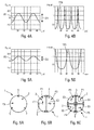
figures 4A et 4B sont des graphiques permettant d'expliquer un premier mode de réglage d'un dispositif d'obturation rapide conforme à l'invention. - Les
figures 5A et 5B sont des graphiques permettant d'expliquer un second mode de réglage d'un dispositif d'obturation rapide conforme à l'invention. - Les
figures 6A, 6B et 6C montrent différents modes de réalisation d'un dispositif d'obturation rapide conforme à l'invention. - Les
figures 7A et 7B illustrent très schématiquement un mode de réalisation particulier d'un dispositif d'obturation rapide conforme à l'invention.
- La
- there is provided a Fabry-Perot cavity having an adjustable spacing, a so-called nominal spacing value allows passage through said Fabry-Perot cavity for a laser radiation of corresponding frequency called nominal frequency; and
- said gap is rapidly varied, by deformation or spacing of at least one surface of the Fabry-Perot cavity, in a range of spacing values comprising said nominal value, according to a periodic function over time.
The figures of the appended drawing will make it clear how the invention can be realized. In these figures, identical references designate similar elements.- The
figure 1 illustrates very schematically a fast shutter device according to the invention. - The
figure 2 illustrates opening times of the shutter device, associated with a duration of exposure of a camera. - The
figure 3 shows a camera which is associated with a fast shutter device according to the invention. - The
Figures 4A and 4B are graphs for explaining a first mode of adjustment of a fast shutter device according to the invention. - The
Figures 5A and 5B are graphs for explaining a second mode of adjustment of a fast shutter device according to the invention. - The
FIGS. 6A, 6B and 6C show different embodiments of a fast shutter device according to the invention. - The
Figures 7A and 7B illustrate very schematically a particular embodiment of a fast shutter device according to the invention.
- The
Le dispositif optique d'obturation rapide 1 conforme à l'invention et représenté schématiquement sur la
Selon l'invention, ce dispositif optique d'obturation rapide 1 comporte au moins un ensemble 2A, 2B comprenant :
- une cavité de Fabry-
Pérot 3 de type usuel.Cette cavité 3 comprend, de façon usuelle, deux surfaces planes3A et 3B partiellement réfléchissantes, à coefficients de réflexions élevés.Ladite cavité 3 présente un écartement E réglable (correspondant à l'écartement entre les deux surfaces3A et 3B), dont une valeur d'écartement E0 dite nominale permet un passage à travers ladite cavité de Fabry-Pérot pourune impulsion laser 4 de fréquence correspondante dite fréquence nominale, comme précisé ci-dessous ; et - des actionneurs piézo-
électriques
- a Fabry-
Perot 3 cavity of the usual type. Thiscavity 3 comprises, in the usual way, two partially reflectiveflat surfaces cavity 3 has an adjustable spacing E (corresponding to the spacing between the twosurfaces laser pulse 4 of corresponding frequency called nominal frequency, as specified below; and -
piezoelectric actuators
Dans le mode de réalisation de la
Ledit dispositif 1 comporte de plus, selon l'invention, une unité de commande 6 qui est reliée par l'intermédiaire d'une liaison 7 auxdits actionneurs piézo-électriques 5A, 5B et qui est formée de manière à commander lesdits actionneurs 5A, 5B de sorte qu'ils fassent varier l'écartement E selon une fonction F1, F2 qui est périodique au cours du temps. De préférence, cette fonction périodique F1, F2 est de type sinusoïdal.
On sait qu'une cavité de Fabry-Pérot 3 présente une transmission de lumière qui est très sensible à la longueur d'onde. Selon la valeur de l'écartement E, la transmission pour une longueur d'onde donnée peut varier d'une transmission nulle à une transmission complète. En modifiant la taille de l'écartement E de la cavité de Fabry-Pérot 3, on peut donc facilement contrôler la transmission pour une longueur d'onde spécifique. Des changements rapides de taille de l'écartement E permettent ainsi la mise en oeuvre d'une fonction d'obturation.It is known that a Fabry-
Cependant, l'inertie mécanique de l'ensemble 2A, 2B autorise uniquement un temps de réponse d'environ 1ms. Pour obtenir un temps de réponse beaucoup plus court de l'ordre de 1µs, le dispositif 1 fonctionne à la résonance, en commandant les actionneurs piézo-électriques 5A, 5B avec une fonction périodique, de préférence sinusoïdale. La fréquence de résonance peut être gérée par l'intermédiaire de la forme et du facteur de forme de différentes parties de la cavité de Fabry-Pérot 3.However, the mechanical inertia of the
Grâce à ces caractéristiques, le dispositif d'obturation 1 conforme à l'invention est apte à s'ouvrir et se fermer à fréquences élevées (1 khz à 50khz). Chaque ouverture 8 (
La cavité de Fabry-Pérot 3 est donc configurée pour devenir transparente à la longueur d'onde considérée de l'impulsion laser 4, uniquement si la taille de l'écartement E passe à la valeur nominale E0 représentative de cette longueur d'onde. Cette situation peut se présenter plusieurs fois à chaque cycle de la fonction sinusoïdale F1 et F2, mais elle dure un court temps uniquement. Le fait de fonctionner à la résonance permet alors un temps d'ouverture de 1µs ou moins pour le dispositif 1.The Fabry-
En outre, ledit dispositif optique d'obturation rapide 1 comporte également des moyens de réglage 10 qui sont, par exemple, reliés par une liaison 11 à l'unité de commande 6 et qui permettent à un opérateur de régler, notamment, la fréquence de résonance de ladite cavité de Fabry-Pérot 3, la fréquence nominale ainsi que la durée d'ouverture pour la fréquence nominale et la durée de répétition de l'ouverture.In addition, said fast shutter
Plus précisément :
- l'ajustement des paramètres de la résonance de la cavité permet un réglage de la durée d'ouverture (ou temps pendant lequel la cavité optique 3 permet le passage du rayonnement laser monochromatique (ou impulsion laser) 4) ; et
- la forme et le facteur de forme des différentes parties du dispositif 1 permettent un réglage de la fréquence.
- adjusting the resonance parameters of the cavity allows adjustment of the opening time (or time during which the
optical cavity 3 allows the passage of monochromatic laser radiation (or laser pulse) 4); and - the shape and form factor of the different parts of the
device 1 allow adjustment of the frequency.
Le dispositif 1 peut ainsi générer une fonction d'expositions multiples de courtes durées.The
Si la cavité 3 est ajustée pour avoir une transmission totale de l'impulsion laser 4 au repos (valeur médiane) de la fonction de commande F1, l'excitation de la résonance interdit le passage de cette impulsion laser 4 pour l'essentiel du temps T, mais la laisse passer au repos (écartement nominal de 20 µm).If the
Cette situation est représentée sur les
- la variation de l'écartement E de la cavité 3 (exprimée en µm) en fonction du temps T (exprimé en µs), qui vérifie une fonction F1 de type sinusoïdale ; et
- la transmission correspondante TR1 (exprimée en dB) de l'impulsion
laser 4, àtravers l'ensemble 2, en fonction dudit temps T.
- the variation of the gap E of the cavity 3 (expressed in μm) as a function of the time T (expressed in μs), which satisfies a sinusoidal F1 function; and
- the corresponding transmission TR1 (expressed in dB) of the
laser pulse 4, through theset 2, as a function of said time T.
Dans cet exemple, pour laquelle la cavité 3 est réglée pour laisser passer l'impulsion laser 4 au repos de la fonction F1 (environ aux temps T : 12 µs, 34 µs), l'ouverture est réalisée environ toutes les 20 µs (durée de répétition de l'ouverture) et elle dure moins de 1 µs (durée d'ouverture).In this example, for which the
Si la cavité est ajustée pour avoir une transmission nulle au repos, l'excitation de la résonance permet au rayonnement laser de traverser la cavité 3 uniquement lorsqu'elle atteint la valeur d'écartement adéquate (20 µm).If the cavity is adjusted to have a zero transmission at rest, the excitation of the resonance allows the laser radiation to pass through the
Cette situation est représentée sur les
- la variation de l'écartement E de la cavité 3 (exprimée en µm) en fonction du temps T (exprimé en µs), qui vérifie une fonction F2 de type sinusoïdale ; et
- la transmission correspondante TR2 (exprimée de dB) de l'impulsion
laser 4 àtravers l'ensemble 2 en fonction dudit temps T.
- the variation of the gap E of the cavity 3 (expressed in μm) as a function of the time T (expressed in μs), which satisfies a sinusoidal function F2; and
- the corresponding transmission TR2 (expressed in dB) of the
laser pulse 4 through theset 2 as a function of said time T.
Dans cet exemple, pour laquelle la cavité 3 est réglée pour laisser passer l'impulsion laser 4 lorsque la fonction F2 atteint la valeur minimaleIn this example, for which the
(environ au temps T : 0 µs, 45 µs), la vitesse de l'ouverture est plus lente, mais elle dure plus longtemps, près de 5 µs.(At time T: 0 μs, 45 μs), the aperture speed is slower, but lasts longer, close to 5 μs.
La présente invention prévoit d'utiliser une cavité de Fabry-Pérot de forte finesse (très sélective en longueur d'onde) pour transformer une oscillation mécanique de longue période (typiquement la milliseconde ou la dixième de milliseconde) en un temps d'obturation beaucoup plus rapide (typiquement la microseconde).The present invention provides for using a high finesse (very wavelength selective) Fabry-Perot cavity to transform a long-period mechanical oscillation (typically millisecond or tenth of a millisecond) into a very long shutter time. faster (typically the microsecond).
Par ailleurs, dans un mode de réalisation particulier représenté sur les
Sur la
En revanche, dans la situation de la
Dans un mode de réalisation simplifié, le dispositif 1 comporte un seul ensemble 2 qui est agencé au niveau d'une pupille d'entrée P0, comme représenté schématiquement sur la
Comme indiqué ci-dessus en étant placé devant les optiques de la caméra 20, à proximité de la position de la pupille d'entrée, le dispositif d'obturation rapide 1, est apte à créer une capacité de générer de courtes expositions multiples pour le faisceau laser 4.As indicated above by being placed in front of the optics of the
Dans un mode de réalisation particulier, ledit dispositif optique d'obturation 1 comporte une pluralité d'ensembles 2 (comprenant chacun une cavité de Fabry-Pérot 3) qui sont répartis sur une pupille d'entrée notamment d'une caméra 20. Dans ce cas, lesdites cavités de Fabry-Pérot 3 sont configurées pour être commandées indépendamment. De plus, ledit dispositif optique d'obturation 1 comporte une pluralité de polariseurs (non représentés), dont chacun est associé à l'une desdites cavités de Fabry-Pérot 3.In a particular embodiment, said
L'architecture du dispositif 1 est ainsi divisée en plusieurs sous-pupilles, par exemple :
- en deux sous-pupilles similaires P1 et P2, comme représenté sur la
figure 6B avec des polarisations respectives E1 et E2 ; ou - en quatre sous-pupilles similaires P3 à P6, comme représenté sur la
figure 6C avec des polarisations respectives E3 à E6.
- in two similar sub-pupils P1 and P2, as shown on the
Figure 6B with respective polarizations E1 and E2; or - in four similar sub-pupils P3 to P6, as shown in FIG.
Figure 6C with respective polarizations E3 to E6.
Les différents éléments 3 et 5 peuvent être pilotés indépendamment pour ouvrir l'une ou l'autre sous-pupille selon le besoin.The
Ce mode de réalisation des
Dans une application préférée, ledit dispositif 1 fait ainsi partie d'un système d'observation actif (non représenté). Ce système d'observation actif comporte :
- au moins une source laser, qui est apte à émettre au moins une impulsion
laser 4 ; ledit dispositif 1 qui est susceptible d'être amené, de façon alternative, dans une position ouverte, dans laquelle il laisse passerladite impulsion laser 4, et une position fermée dans laquelle il empêche le passage de ladite impulsionlaser 4 ;
une caméra 20 susceptible de prendre l'image d'un champ de vision illuminé par ladite source laser, autravers dudit dispositif 1 ; et- une unité de commande qui commande simultanément ladite source laser, ledit dispositif et ladite caméra.
- at least one laser source, which is capable of emitting at least one
laser pulse 4; - said
device 1 which can be alternatively brought into an open position in which it passes saidlaser pulse 4, and a closed position in which it prevents the passage of saidlaser pulse 4;
- a
camera 20 capable of taking the image of a field of vision illuminated by said laser source, through saiddevice 1; and - a control unit which simultaneously controls said laser source, said device and said camera.
Dans ce cas, le dispositif d'obturation rapide 1 est placé devant les optiques de la caméra 20, à proximité de la position de la pupille d'entrée, pour créer une capacité de générer de courtes expositions multiples, pour le faisceau laser 4, comme illustré sur la
La caméra 20 est exposée de préférence pendant un temps d'exposition 13 qui est tel qu'il contient plusieurs ouvertures 8 du dispositif 1 et donc plusieurs expositions successives au faisceau laser 4 (émis par la source laser et réfléchie par la scène à observer), comme représenté schématiquement sur la
On notera que, grâce à l'invention, on peut utiliser sur le système actif :
- tout type de caméra ; et
- notamment une source laser de type à semi-conducteurs, qui est fiable, peut être facilement intégrée et présente un coût réduit.
- any type of camera; and
- In particular, a semiconductor-type laser source, which is reliable, can be easily integrated and has a reduced cost.
Claims (12)
caractérisé en ce que lesdits moyens d'actionnement (5A) de type piézo-électrique, sont configurés pour modifier uniformément l'espacement entre deux surfaces parallèles (3A, 3B) de la cavité de Fabry-Pérot (3), afin de faire varier ledit écartement (E).Device according to claim 1,
characterized in that said piezoelectric-type actuating means (5A) are configured to uniformly change the spacing between two parallel surfaces (3A, 3B) of the Fabry-Perot cavity (3) to vary said gap (E).
caractérisé en ce que lesdits moyens d'actionnement (5B) de type piézo-électrique, sont configurés pour déformer ladite cavité de Fabry-Pérot (3), afin de faire varier ledit écartement (E).Device according to claim 1,
characterized in that said piezoelectric type actuating means (5B) are configured to deform said Fabry-Perot cavity (3) to vary said gap (E).
caractérisé en ce que ladite fonction (F1, F2) périodique est de type sinusoïdal.Device according to one of claims 1 to 3,
characterized in that said periodic function (F1, F2) is of sinusoidal type.
caractérisé en ce que lesdites cavités de Fabry-Pérot (3) sont configurées pour être commandées indépendamment.Device according to claim 7,
characterized in that said Fabry-Perot cavities (3) are configured to be independently controlled.
caractérisé en ce qu'il comporte une pluralité de polariseurs, dont chacun est associé à l'une desdites cavités de Fabry-Pérot (3).Device according to one of claims 7 and 8,
characterized in that it comprises a plurality of polarizers, each of which is associated with one of said Fabry-Perot cavities (3).
caractérisé en ce que ledit obturateur comprend un dispositif optique d'obturation rapide (1), tel que celui spécifié sous l'une quelconque des revendications 1 à 9.
characterized in that said shutter comprises a fast shutter optical device (1), such as that specified in any one of claims 1 to 9.
caractérisé en ce que :
characterized in that
Applications Claiming Priority (1)
| Application Number | Priority Date | Filing Date | Title |
|---|---|---|---|
| FR1301100A FR3005750B1 (en) | 2013-05-14 | 2013-05-14 | OPTICAL DEVICE FOR RAPID SHUTTERING. |
Publications (1)
| Publication Number | Publication Date |
|---|---|
| EP2804032A1 true EP2804032A1 (en) | 2014-11-19 |
Family
ID=49474453
Family Applications (1)
| Application Number | Title | Priority Date | Filing Date |
|---|---|---|---|
| EP20140167311 Withdrawn EP2804032A1 (en) | 2013-05-14 | 2014-05-07 | Quick-shutter optical device |
Country Status (4)
| Country | Link |
|---|---|
| US (1) | US20140340514A1 (en) |
| EP (1) | EP2804032A1 (en) |
| FR (1) | FR3005750B1 (en) |
| IL (1) | IL232597A (en) |
Families Citing this family (3)
| Publication number | Priority date | Publication date | Assignee | Title |
|---|---|---|---|---|
| CN107611757B (en) * | 2017-09-23 | 2024-04-19 | 华南理工大学 | Two-section type weak modulation F-P cavity |
| JP2019082349A (en) * | 2017-10-30 | 2019-05-30 | セイコーエプソン株式会社 | Spectrometer and spectroscopic method |
| CN108983417A (en) * | 2018-05-25 | 2018-12-11 | 中国科学技术大学 | A kind of optical filter, Doppler anemometry laser radar and Wind field measurement method |
Citations (5)
| Publication number | Priority date | Publication date | Assignee | Title |
|---|---|---|---|---|
| US20040218187A1 (en) * | 2002-03-18 | 2004-11-04 | Cole Barrett E. | Multiple wavelength spectrometer |
| US20090027518A1 (en) * | 2007-07-24 | 2009-01-29 | Casio Computer Co., Ltd. | Image pick-up apparatus and method of controlling the image pick-up apparatus |
| EP2367044A1 (en) * | 2010-03-15 | 2011-09-21 | Seiko Epson Corporation | Optical filter, optical filter module, analytical instrument, and optical apparatus |
| EP2405294A1 (en) * | 2010-07-06 | 2012-01-11 | Seiko Epson Corporation | Optical filter, optical filter module, spectrometric measurement apparatus, and optical apparatus |
| EP2555037A1 (en) * | 2010-03-30 | 2013-02-06 | Olympus Corporation | Variable spectral element |
Family Cites Families (2)
| Publication number | Priority date | Publication date | Assignee | Title |
|---|---|---|---|---|
| US7586602B2 (en) * | 2006-07-24 | 2009-09-08 | General Electric Company | Method and apparatus for improved signal to noise ratio in Raman signal detection for MEMS based spectrometers |
| US8687983B2 (en) * | 2011-11-02 | 2014-04-01 | Hewlett-Packard Development Company, L.P. | Laser communication system |
-
2013
- 2013-05-14 FR FR1301100A patent/FR3005750B1/en active Active
-
2014
- 2014-05-07 EP EP20140167311 patent/EP2804032A1/en not_active Withdrawn
- 2014-05-13 US US14/276,437 patent/US20140340514A1/en not_active Abandoned
- 2014-05-13 IL IL232597A patent/IL232597A/en not_active IP Right Cessation
Patent Citations (5)
| Publication number | Priority date | Publication date | Assignee | Title |
|---|---|---|---|---|
| US20040218187A1 (en) * | 2002-03-18 | 2004-11-04 | Cole Barrett E. | Multiple wavelength spectrometer |
| US20090027518A1 (en) * | 2007-07-24 | 2009-01-29 | Casio Computer Co., Ltd. | Image pick-up apparatus and method of controlling the image pick-up apparatus |
| EP2367044A1 (en) * | 2010-03-15 | 2011-09-21 | Seiko Epson Corporation | Optical filter, optical filter module, analytical instrument, and optical apparatus |
| EP2555037A1 (en) * | 2010-03-30 | 2013-02-06 | Olympus Corporation | Variable spectral element |
| EP2405294A1 (en) * | 2010-07-06 | 2012-01-11 | Seiko Epson Corporation | Optical filter, optical filter module, spectrometric measurement apparatus, and optical apparatus |
Also Published As
| Publication number | Publication date |
|---|---|
| IL232597A0 (en) | 2014-08-31 |
| FR3005750A1 (en) | 2014-11-21 |
| IL232597A (en) | 2017-06-29 |
| FR3005750B1 (en) | 2016-09-16 |
| US20140340514A1 (en) | 2014-11-20 |
Similar Documents
| Publication | Publication Date | Title |
|---|---|---|
| EP2804011B1 (en) | Laser illumination device with built-in shutter | |
| WO2009153446A2 (en) | Device for projecting structured light using vcsels and phase diffractive optical components | |
| EP4090993A1 (en) | Coherent lidar imaging system | |
| FR3049719A1 (en) | DEVICES AND METHODS FOR TRANSPORTING AND CONTROLLING LUMINOUS BEAMS FOR ENDO-MICROSCOPIC IMAGING WITHOUT LENS | |
| EP2804032A1 (en) | Quick-shutter optical device | |
| FR3021111A1 (en) | WAVELENGTH-CONNECTABLE PYROMETER FOR RADIOMETRICALLY MEASURING THE TEMPERATURE OF A BODY | |
| FR3064355A1 (en) | FOURIER TRANSFORMED SPECTROMETER AND METHOD FOR MANAGING THE SAME | |
| WO2010089511A1 (en) | Double prism autocorrelation device for the time measurement of ultra-short light pulses | |
| EP3491330B1 (en) | Full-field interferential imaging systems and methods | |
| EP3936887B1 (en) | Lidar coherent system with improved signal-to-noise ratio | |
| FR2588653A1 (en) | POSITION OPTICAL SENSOR | |
| FR3058235A1 (en) | OPTICAL DE-PHASE AND PHASE-CONTROLLED OPTICAL DEVICE, AND PHASE-ADJUSTING METHOD | |
| EP2232307B1 (en) | Laser pointing system | |
| FR2892514A1 (en) | TERAHERTZ BANDWIDTH ELECTROMAGNETIC WAVE DETECTOR | |
| EP4224203A2 (en) | Imaging lidar apparatus and methods for operation in day-light conditions | |
| FR2765964A1 (en) | Optical distance measuring system using precision interferometers | |
| FR2816455A1 (en) | WAVELENGTH MONITORING DEVICE AND WAVELENGTH STABILIZATION LIGHT SOURCE | |
| FR2857756A1 (en) | Ladar type remote detection and/or measurement device for e.g. imaging device, has two control units to polarize laser cells in photo-emitter and photo-detector modes to permit cells to detect optical energy backscattered by imaging system | |
| FR3059156B1 (en) | OPTICAL DETECTION MODULE | |
| WO2005066653A1 (en) | Laser active optronic system with improved detectivity | |
| FR3098931A1 (en) | FREQUENCY CONVERSION ACTIVE IMAGING SYSTEM | |
| EP3913395A1 (en) | Improved detector with deflecting elements for coherent imaging | |
| EP0911645A1 (en) | Optical apparatus with polarisation modulation for measuring distance to, or velocity of, an object | |
| FR3004253A1 (en) | HIGH SENSITIVITY WAVEFRONT MEASUREMENT METHOD AND CORRESPONDING MEASURER | |
| FR2790336A1 (en) | Industrial rapidly deflectable laser beam optical unit having cavity generated beam mirror cavity passed and in line diffraction cavity providing commandable beam offset |
Legal Events
| Date | Code | Title | Description |
|---|---|---|---|
| PUAI | Public reference made under article 153(3) epc to a published international application that has entered the european phase |
Free format text: ORIGINAL CODE: 0009012 |
|
| 17P | Request for examination filed |
Effective date: 20140507 |
|
| AK | Designated contracting states |
Kind code of ref document: A1 Designated state(s): AL AT BE BG CH CY CZ DE DK EE ES FI FR GB GR HR HU IE IS IT LI LT LU LV MC MK MT NL NO PL PT RO RS SE SI SK SM TR |
|
| AX | Request for extension of the european patent |
Extension state: BA ME |
|
| R17P | Request for examination filed (corrected) |
Effective date: 20150511 |
|
| RBV | Designated contracting states (corrected) |
Designated state(s): AL AT BE BG CH CY CZ DE DK EE ES FI FR GB GR HR HU IE IS IT LI LT LU LV MC MK MT NL NO PL PT RO RS SE SI SK SM TR |
|
| STAA | Information on the status of an ep patent application or granted ep patent |
Free format text: STATUS: THE APPLICATION IS DEEMED TO BE WITHDRAWN |
|
| 18D | Application deemed to be withdrawn |
Effective date: 20181201 |