EP2804032A1 - Optische Vorrichtung mit Schnellverschluss - Google Patents
Optische Vorrichtung mit Schnellverschluss Download PDFInfo
- Publication number
- EP2804032A1 EP2804032A1 EP20140167311 EP14167311A EP2804032A1 EP 2804032 A1 EP2804032 A1 EP 2804032A1 EP 20140167311 EP20140167311 EP 20140167311 EP 14167311 A EP14167311 A EP 14167311A EP 2804032 A1 EP2804032 A1 EP 2804032A1
- Authority
- EP
- European Patent Office
- Prior art keywords
- fabry
- spacing
- perot
- nominal
- gap
- Prior art date
- Legal status (The legal status is an assumption and is not a legal conclusion. Google has not performed a legal analysis and makes no representation as to the accuracy of the status listed.)
- Withdrawn
Links
- 230000003287 optical effect Effects 0.000 title claims description 28
- 230000005855 radiation Effects 0.000 claims abstract description 16
- 230000000737 periodic effect Effects 0.000 claims abstract description 14
- 210000001747 pupil Anatomy 0.000 claims description 9
- 238000000034 method Methods 0.000 claims description 2
- 230000005540 biological transmission Effects 0.000 description 13
- 230000010287 polarization Effects 0.000 description 5
- 241000287107 Passer Species 0.000 description 2
- 238000001514 detection method Methods 0.000 description 2
- 230000005284 excitation Effects 0.000 description 2
- 230000000712 assembly Effects 0.000 description 1
- 238000000429 assembly Methods 0.000 description 1
- 230000007123 defense Effects 0.000 description 1
- 238000005286 illumination Methods 0.000 description 1
- 230000010358 mechanical oscillation Effects 0.000 description 1
Images


Classifications
-
- G—PHYSICS
- G01—MEASURING; TESTING
- G01J—MEASUREMENT OF INTENSITY, VELOCITY, SPECTRAL CONTENT, POLARISATION, PHASE OR PULSE CHARACTERISTICS OF INFRARED, VISIBLE OR ULTRAVIOLET LIGHT; COLORIMETRY; RADIATION PYROMETRY
- G01J3/00—Spectrometry; Spectrophotometry; Monochromators; Measuring colours
- G01J3/02—Details
- G01J3/0205—Optical elements not provided otherwise, e.g. optical manifolds, diffusers, windows
- G01J3/0232—Optical elements not provided otherwise, e.g. optical manifolds, diffusers, windows using shutters
-
- H—ELECTRICITY
- H04—ELECTRIC COMMUNICATION TECHNIQUE
- H04N—PICTORIAL COMMUNICATION, e.g. TELEVISION
- H04N23/00—Cameras or camera modules comprising electronic image sensors; Control thereof
- H04N23/70—Circuitry for compensating brightness variation in the scene
- H04N23/73—Circuitry for compensating brightness variation in the scene by influencing the exposure time
-
- G—PHYSICS
- G01—MEASURING; TESTING
- G01J—MEASUREMENT OF INTENSITY, VELOCITY, SPECTRAL CONTENT, POLARISATION, PHASE OR PULSE CHARACTERISTICS OF INFRARED, VISIBLE OR ULTRAVIOLET LIGHT; COLORIMETRY; RADIATION PYROMETRY
- G01J3/00—Spectrometry; Spectrophotometry; Monochromators; Measuring colours
- G01J3/12—Generating the spectrum; Monochromators
- G01J3/26—Generating the spectrum; Monochromators using multiple reflection, e.g. Fabry-Perot interferometer, variable interference filters
-
- G—PHYSICS
- G02—OPTICS
- G02B—OPTICAL ELEMENTS, SYSTEMS OR APPARATUS
- G02B26/00—Optical devices or arrangements for the control of light using movable or deformable optical elements
- G02B26/001—Optical devices or arrangements for the control of light using movable or deformable optical elements based on interference in an adjustable optical cavity
-
- G—PHYSICS
- G02—OPTICS
- G02B—OPTICAL ELEMENTS, SYSTEMS OR APPARATUS
- G02B26/00—Optical devices or arrangements for the control of light using movable or deformable optical elements
- G02B26/02—Optical devices or arrangements for the control of light using movable or deformable optical elements for controlling the intensity of light
-
- G—PHYSICS
- G02—OPTICS
- G02B—OPTICAL ELEMENTS, SYSTEMS OR APPARATUS
- G02B5/00—Optical elements other than lenses
- G02B5/20—Filters
- G02B5/28—Interference filters
- G02B5/284—Interference filters of etalon type comprising a resonant cavity other than a thin solid film, e.g. gas, air, solid plates
-
- H—ELECTRICITY
- H04—ELECTRIC COMMUNICATION TECHNIQUE
- H04N—PICTORIAL COMMUNICATION, e.g. TELEVISION
- H04N23/00—Cameras or camera modules comprising electronic image sensors; Control thereof
- H04N23/56—Cameras or camera modules comprising electronic image sensors; Control thereof provided with illuminating means
-
- H—ELECTRICITY
- H04—ELECTRIC COMMUNICATION TECHNIQUE
- H04N—PICTORIAL COMMUNICATION, e.g. TELEVISION
- H04N23/00—Cameras or camera modules comprising electronic image sensors; Control thereof
- H04N23/70—Circuitry for compensating brightness variation in the scene
- H04N23/74—Circuitry for compensating brightness variation in the scene by influencing the scene brightness using illuminating means
-
- H—ELECTRICITY
- H04—ELECTRIC COMMUNICATION TECHNIQUE
- H04N—PICTORIAL COMMUNICATION, e.g. TELEVISION
- H04N23/00—Cameras or camera modules comprising electronic image sensors; Control thereof
- H04N23/50—Constructional details
- H04N23/55—Optical parts specially adapted for electronic image sensors; Mounting thereof
-
- H—ELECTRICITY
- H04—ELECTRIC COMMUNICATION TECHNIQUE
- H04N—PICTORIAL COMMUNICATION, e.g. TELEVISION
- H04N23/00—Cameras or camera modules comprising electronic image sensors; Control thereof
- H04N23/70—Circuitry for compensating brightness variation in the scene
- H04N23/75—Circuitry for compensating brightness variation in the scene by influencing optical camera components
Definitions
- the present invention relates to an optical fast shutter device. It also relates to an active observation system comprising such an optical quick shutter device, in particular for defense and security applications.
- an active observation system is configured to illuminate a scene of the environment using a laser source, in order to improve the quality of an image of said scene and / or to highlight some specific details, such as pointed optics for example.
- said observation system comprises a laser source with a specific beam shape generation optics and a reception camera capable of producing an image of the illuminated scene.
- a feature of an active system as considered is its ability to illuminate only a restricted portion of the space. To do this, the camera is sensitive to incoming light for a very short time, typically between 0.1 ⁇ s and 10 ⁇ s. If the laser illumination also uses a short pulse, the combination with the short exposure time of the camera results in a selection of photons which correspond to a rather limited travel time.
- the generated image corresponds to a part of the space (in distance) with respect to the position of the active system (typically from a few tens to a few hundred meters).
- the field of view can thus be defined not only in plan (according to the usual vision plane), but also according to the distance to the active system, that is to say in volume.
- some lasers require multiple exposures of very short duration to achieve the energy required to form an image with an acceptable signal-to-noise ratio.
- the present invention relates to a fast shutter optical device for providing a capacity of multiple short-term exposures to any associated optical element and in particular to cameras.
- Rapid changes in the size of the gap of the cavity allow the realization of the shutter function.
- the fast shutter device operates at the mechanical resonance of the cavity, by controlling the piezoelectric actuators with a periodic function, in particular sinusoidal.
- the resonance frequency can be managed through the shape and form factor of different parts of the Fabry-Perot cavity. It is for example possible to obtain a resonance at 5kHz.
- the cavity then becomes transparent for radiation of a given wavelength, only if the size of the spacing of the Fabry-Perot cavity goes to the corresponding appropriate value. This situation can occur several times with each cycle of the periodic control function, preferably sinusoidal, but it lasts only a short time.
- the shutter device according to the invention can open and close at high frequencies (1 khz to 50khz), each opening for a very short time (0.1 microseconds to 10 microseconds).
- Said device shutter has no optical power and achieves only a transmission function that varies rapidly.
- Said fast shutter device can be placed in front of the optics of an optical sensor and in particular a camera, close to the position of the entrance pupil, to create a capacity to generate short multiple exposures, for the light entering.
- said periodic type actuating means are configured to uniformly modify the spacing between two parallel surfaces of the Fabry-Perot cavity, in order to vary said spacing.
- said periodic type actuating means are configured to deform said Fabry-Perot cavity, in order to vary said gap.
- said optical shutter device comprises a plurality of Fabry-Perot cavities which are distributed over the same optical surface, preferably representing an entrance pupil of an optical element and notably a camera. .
- said Fabry-Perot cavities are configured to be controlled independently.
- said optical shutter device comprises a plurality of polarizers, each of which is associated with one of said Fabry-Perot cavities.
- this active observation system is remarkable in that said shutter comprises a fast shutter optical device, such as the one mentioned above, which is then placed in front of the optics of the camera, close to the position of the camera. entrance pupil, to create an ability to generate multiple short exposures for incoming light.
- a fast shutter optical device such as the one mentioned above
- the entrance pupil of the camera comprises a plurality of sub-pupils each having a Fabry-Perot cavity.
- each sub-pupil can be coupled to a polarizer in order to select only a state of polarization coming from the scene.
- the analysis of images thus polarized allows in particular a detection of hidden objects in the scene.
- the fast shutter optical device 1 according to the invention and shown schematically on the figure 1 is intended to provide a capacity for multiple short-term exposures to any associated optical element, and in particular to a camera 20 ( figure 3 ), placed between this device 1 and a laser beam emission site (including a scene returning a beam generated by a laser source).
- said piezoelectric actuators 5A of the assembly 2A are configured to vary, parallel and uniformly, the spacing (defining the spacing E) between the two surfaces 3A, 3B of the Fabry-Perot cavity 3 which are parallel .
- the spacing remains uniform between the two surfaces 3A and 3B of the cavity 3.
- another embodiment (generating a deformation of the Fabry-Perot cavity 3) is also possible, as specified below with reference to FIGS. Figures 7A and 7B .
- Said device 1 further comprises, according to the invention, a control unit 6 which is connected via a link 7 to said piezoelectric actuators 5A, 5B and which is formed so as to control said actuators 5A, 5B so that they vary the distance E according to a function F1, F2 which is periodic over time.
- this periodic function F1, F2 is of the sinusoidal type.
- a Fabry-Perot cavity 3 has a light transmission which is very sensitive to the wavelength. Depending on the value of the gap E, the transmission for a given wavelength may vary from zero transmission to full transmission. By changing the size of the gap E of the Fabry-Perot cavity 3, it is therefore easy to control the transmission for a specific wavelength. Rapid changes in the size of the gap E thus allow the implementation of a shutter function.
- the mechanical inertia of the assembly 2A, 2B only allows a response time of about 1ms.
- the device 1 operates at resonance, by controlling the piezoelectric actuators 5A, 5B with a periodic function, preferably sinusoidal.
- the resonance frequency can be managed through the shape and form factor of different parts of the Fabry-Perot 3 cavity.
- the shutter device 1 according to the invention is able to open and close at high frequencies (1 khz to 50khz).
- the fast shutter optical device 1 has no optical power and only performs a rapidly changing transmission function.
- the Fabry-Perot cavity 3 is therefore configured to become transparent at the considered wavelength of the laser pulse 4, only if the size of the gap E goes to the nominal value E 0 representative of this wavelength. This situation may occur several times during each cycle of the F1 and F2 sine function, but it lasts only a short time. Running at resonance then allows an opening time of 1 ⁇ s or less for device 1.
- said fast shutter optical device 1 also comprises adjustment means 10 which are, for example, connected by a link 11 to the control unit 6 and which allow an operator to adjust, in particular, the frequency of resonance of said Fabry-Perot cavity 3, the nominal frequency as well as the duration of opening for the nominal frequency and the duration of repetition of the opening.
- the device 1 can thus generate a function of multiple exposures of short durations.
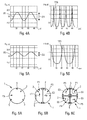
- the excitation of the resonance prohibits the passage of this laser pulse 4 for most of the time T, but let it go to rest (nominal spacing of 20 microns).
- the opening is made approximately every 20 ⁇ s (duration repetition of the opening) and it lasts less than 1 ⁇ s (opening time).
- the excitation of the resonance allows the laser radiation to pass through the cavity 3 only when it reaches the appropriate spacing value (20 microns).
- the aperture speed is slower, but lasts longer, close to 5 ⁇ s.
- the present invention provides for using a high finesse (very wavelength selective) Fabry-Perot cavity to transform a long-period mechanical oscillation (typically millisecond or tenth of a millisecond) into a very long shutter time. faster (typically the microsecond).
- a high finesse (very wavelength selective) Fabry-Perot cavity to transform a long-period mechanical oscillation (typically millisecond or tenth of a millisecond) into a very long shutter time. faster (typically the microsecond).
- said piezoelectric actuators 5B of the assembly 2B are configured to generate a deformation of the Fabry-Perot cavity 3.
- the cavity 3 has the appropriate spacing E to let the laser beam 4 (with a parallel arrangement of the two surfaces 3A and 3B).
- the piezoelectric actuators 5B have been actuated so as to deform the cavity 3 (by acting on the surface 3A).
- This deformation (illustrated by an arrow 15) causes the inner face 14A of the surface 3A (opposite to the inner face 14B of the surface 3B) is slightly curved and convex, which modifies the spacing between the two surfaces 3A and 3B which is no longer constant.
- the spacing between the two surfaces 3A and 3B is different from the nominal spacing, at least at the passage (arrow 15) of the laser pulse 4. Said laser pulse 4 is then reflected and can not cross the Fabry-Perot cavity 3.
- the device 1 comprises a single assembly 2 which is arranged at the level of an entrance pupil P0, as shown schematically in FIG. Figure 6A .
- the fast shutter device 1 is able to create a capacity to generate multiple short exposures for the camera. laser beam 4.
- said optical shutter device 1 comprises a plurality of assemblies 2 (each comprising a Fabry-Perot cavity 3) which are distributed over an entrance pupil, in particular a camera 20.
- said Fabry-Perot cavities 3 are configured to be controlled independently.
- said optical shutter device 1 comprises a plurality of polarizers (not shown), each of which is associated with one of said Fabry-Perot cavities 3.
- the various elements 3 and 5 can be controlled independently to open one or the other sub-pupil as needed.
- each sub-pupil can thus be coupled to a polarizer in order to select only a state of polarization coming from the scene.
- the analysis of images thus polarized allows detection of hidden objects in the scene, especially when these objects have a polarization different from the natural elements (eg the vegetation of the scene).
- the fast shutter device 1 is placed in front of the optics of the camera 20, close to the position of the entrance pupil, to create a capacity to generate multiple short exposures, for the laser beam 4, as illustrated on the figure 3 .
- the camera 20 is preferably exposed during an exposure time 13 which is such that it contains several openings 8 of the device 1 and therefore several successive exposures to the laser beam 4 (emitted by the laser source and reflected by the scene to be observed) , as shown schematically on the figure 2 so that the camera 20 can receive the energy necessary to form an image with a satisfactory signal-to-noise ratio.
Applications Claiming Priority (1)
| Application Number | Priority Date | Filing Date | Title |
|---|---|---|---|
| FR1301100A FR3005750B1 (fr) | 2013-05-14 | 2013-05-14 | Dispositif optique d'obturation rapide. |
Publications (1)
| Publication Number | Publication Date |
|---|---|
| EP2804032A1 true EP2804032A1 (de) | 2014-11-19 |
Family
ID=49474453
Family Applications (1)
| Application Number | Title | Priority Date | Filing Date |
|---|---|---|---|
| EP20140167311 Withdrawn EP2804032A1 (de) | 2013-05-14 | 2014-05-07 | Optische Vorrichtung mit Schnellverschluss |
Country Status (4)
| Country | Link |
|---|---|
| US (1) | US20140340514A1 (de) |
| EP (1) | EP2804032A1 (de) |
| FR (1) | FR3005750B1 (de) |
| IL (1) | IL232597A (de) |
Families Citing this family (3)
| Publication number | Priority date | Publication date | Assignee | Title |
|---|---|---|---|---|
| CN107611757B (zh) * | 2017-09-23 | 2024-04-19 | 华南理工大学 | 一种两段式弱调制f-p腔 |
| JP2019082349A (ja) * | 2017-10-30 | 2019-05-30 | セイコーエプソン株式会社 | 分光測定装置及び分光測定方法 |
| CN108983417A (zh) * | 2018-05-25 | 2018-12-11 | 中国科学技术大学 | 一种滤光器、多普勒测风激光雷达以及风场测量方法 |
Citations (5)
| Publication number | Priority date | Publication date | Assignee | Title |
|---|---|---|---|---|
| US20040218187A1 (en) * | 2002-03-18 | 2004-11-04 | Cole Barrett E. | Multiple wavelength spectrometer |
| US20090027518A1 (en) * | 2007-07-24 | 2009-01-29 | Casio Computer Co., Ltd. | Image pick-up apparatus and method of controlling the image pick-up apparatus |
| EP2367044A1 (de) * | 2010-03-15 | 2011-09-21 | Seiko Epson Corporation | Optischer Filter, optisches Filtermodul, Analyseinstrument und optische Vorrichtung |
| EP2405294A1 (de) * | 2010-07-06 | 2012-01-11 | Seiko Epson Corporation | Optischer Filter, optisches Filtermodul, spektrometrische Messvorrichtung und optische Vorrichtung |
| EP2555037A1 (de) * | 2010-03-30 | 2013-02-06 | Olympus Corporation | Variables spektralelement |
Family Cites Families (2)
| Publication number | Priority date | Publication date | Assignee | Title |
|---|---|---|---|---|
| US7586602B2 (en) * | 2006-07-24 | 2009-09-08 | General Electric Company | Method and apparatus for improved signal to noise ratio in Raman signal detection for MEMS based spectrometers |
| US8687983B2 (en) * | 2011-11-02 | 2014-04-01 | Hewlett-Packard Development Company, L.P. | Laser communication system |
-
2013
- 2013-05-14 FR FR1301100A patent/FR3005750B1/fr active Active
-
2014
- 2014-05-07 EP EP20140167311 patent/EP2804032A1/de not_active Withdrawn
- 2014-05-13 IL IL232597A patent/IL232597A/en not_active IP Right Cessation
- 2014-05-13 US US14/276,437 patent/US20140340514A1/en not_active Abandoned
Patent Citations (5)
| Publication number | Priority date | Publication date | Assignee | Title |
|---|---|---|---|---|
| US20040218187A1 (en) * | 2002-03-18 | 2004-11-04 | Cole Barrett E. | Multiple wavelength spectrometer |
| US20090027518A1 (en) * | 2007-07-24 | 2009-01-29 | Casio Computer Co., Ltd. | Image pick-up apparatus and method of controlling the image pick-up apparatus |
| EP2367044A1 (de) * | 2010-03-15 | 2011-09-21 | Seiko Epson Corporation | Optischer Filter, optisches Filtermodul, Analyseinstrument und optische Vorrichtung |
| EP2555037A1 (de) * | 2010-03-30 | 2013-02-06 | Olympus Corporation | Variables spektralelement |
| EP2405294A1 (de) * | 2010-07-06 | 2012-01-11 | Seiko Epson Corporation | Optischer Filter, optisches Filtermodul, spektrometrische Messvorrichtung und optische Vorrichtung |
Also Published As
| Publication number | Publication date |
|---|---|
| IL232597A0 (en) | 2014-08-31 |
| US20140340514A1 (en) | 2014-11-20 |
| IL232597A (en) | 2017-06-29 |
| FR3005750B1 (fr) | 2016-09-16 |
| FR3005750A1 (fr) | 2014-11-21 |
Similar Documents
| Publication | Publication Date | Title |
|---|---|---|
| EP2804011B1 (de) | Laserbeleuchtungsvorrichtung mit integrierter Verschlussblende | |
| WO2009153446A2 (fr) | Dispositif de projection de lumiere structuree au moyen de vcsel et de composants optiques diffractifs de phase | |
| FR2458830A1 (fr) | Systeme de representation optique muni d'un systeme de detection opto-electronique servant a determiner un ecart entre le plan image du systeme de representation et un second plan destine a la representation | |
| FR3019317A1 (fr) | Dispositif de visualisation d'une sequence d'images et systeme de visualisation d'une scene | |
| EP4090993A1 (de) | Kohärentes lidar-abbildungssystem | |
| FR3049719A1 (fr) | Dispositifs et methodes de transport et de controle de faisceaux lumineux pour l'imagerie endo-microscopique sans lentille | |
| EP2804032A1 (de) | Optische Vorrichtung mit Schnellverschluss | |
| FR3021111A1 (fr) | Pyrometre accordable en longueur d'onde pour la mesure par voie radiometrique de la temperature d'un corps | |
| FR3064355A1 (fr) | Spectrometre a transformee de fourier et son procede de gestion | |
| WO2010089511A1 (fr) | Dispositif autocorrelateur a biprisme pour la mesure temporelle d'impulsions de lumiere ultrabreves | |
| EP3491330B1 (de) | Interferenzielle vollfeldbildgebungssysteme und verfahren | |
| EP3936887B1 (de) | Kohärentes lidar-system mit verbessertem signal-rausch-verhältnis | |
| FR2588653A1 (fr) | Capteur optique de position | |
| FR3058235A1 (fr) | Dephaseur optique et dispositif optique a commande de phase ainsi que procede de reglage de la phase | |
| EP2232307B1 (de) | Laserzeigesystem | |
| FR2892514A1 (fr) | Detecteur d'ondes electromagnetiques a bande passante terahertz | |
| EP3615902A1 (de) | Verfahren zur räumlich-spektralen charakterisierung einer polychromatischen gepulsten laserquelle | |
| EP4224203A2 (de) | Bildgebende lidar-vorrichtung und verfahren zum betrieb in tageslichtbedingungen | |
| FR2765964A1 (fr) | Dispositif optique de mesure de distance avec une grande precision | |
| FR2857756A1 (fr) | Dispositif d'imagerie et/ou de mesure a distance, de type ladar | |
| FR3059156B1 (fr) | Module de detection optique | |
| WO2005066653A1 (fr) | Systeme optronique actif laser a detectivite amelioree | |
| FR3098931A1 (fr) | Systeme d'imagerie active a conversion de frequence | |
| EP3913395A1 (de) | Verbesserter detektor mit umlenkelementen für kohärente bildgebung | |
| EP0911645A1 (de) | Optisches Messgerät zur Feststellung der Entfernung zu einem Objekt und/oder der Geschwindigkeit eines Objekts unter Verwendung von modulierter Polarisations |
Legal Events
| Date | Code | Title | Description |
|---|---|---|---|
| PUAI | Public reference made under article 153(3) epc to a published international application that has entered the european phase |
Free format text: ORIGINAL CODE: 0009012 |
|
| 17P | Request for examination filed |
Effective date: 20140507 |
|
| AK | Designated contracting states |
Kind code of ref document: A1 Designated state(s): AL AT BE BG CH CY CZ DE DK EE ES FI FR GB GR HR HU IE IS IT LI LT LU LV MC MK MT NL NO PL PT RO RS SE SI SK SM TR |
|
| AX | Request for extension of the european patent |
Extension state: BA ME |
|
| R17P | Request for examination filed (corrected) |
Effective date: 20150511 |
|
| RBV | Designated contracting states (corrected) |
Designated state(s): AL AT BE BG CH CY CZ DE DK EE ES FI FR GB GR HR HU IE IS IT LI LT LU LV MC MK MT NL NO PL PT RO RS SE SI SK SM TR |
|
| STAA | Information on the status of an ep patent application or granted ep patent |
Free format text: STATUS: THE APPLICATION IS DEEMED TO BE WITHDRAWN |
|
| 18D | Application deemed to be withdrawn |
Effective date: 20181201 |