EP2803929B1 - Wärmetauscher mit Wärmetauscherschläuchen aus Kunststoff - Google Patents
Wärmetauscher mit Wärmetauscherschläuchen aus Kunststoff Download PDFInfo
- Publication number
- EP2803929B1 EP2803929B1 EP14154492.4A EP14154492A EP2803929B1 EP 2803929 B1 EP2803929 B1 EP 2803929B1 EP 14154492 A EP14154492 A EP 14154492A EP 2803929 B1 EP2803929 B1 EP 2803929B1
- Authority
- EP
- European Patent Office
- Prior art keywords
- heat exchanger
- exchanger according
- casing
- reinforcement means
- exchanger tubes
- Prior art date
- Legal status (The legal status is an assumption and is not a legal conclusion. Google has not performed a legal analysis and makes no representation as to the accuracy of the status listed.)
- Active
Links
- 239000000463 material Substances 0.000 title claims description 12
- 239000004033 plastic Substances 0.000 title claims description 12
- 229920003023 plastic Polymers 0.000 title claims description 12
- 239000000945 filler Substances 0.000 claims description 13
- 239000011888 foil Substances 0.000 claims description 12
- 229910052751 metal Inorganic materials 0.000 claims description 3
- 239000002184 metal Substances 0.000 claims description 3
- 230000002787 reinforcement Effects 0.000 claims 8
- 229910052500 inorganic mineral Inorganic materials 0.000 claims 1
- 239000011707 mineral Substances 0.000 claims 1
- 239000007789 gas Substances 0.000 description 9
- 229920002313 fluoropolymer Polymers 0.000 description 8
- 239000003546 flue gas Substances 0.000 description 6
- UGFAIRIUMAVXCW-UHFFFAOYSA-N Carbon monoxide Chemical compound [O+]#[C-] UGFAIRIUMAVXCW-UHFFFAOYSA-N 0.000 description 5
- 238000005192 partition Methods 0.000 description 4
- 229920011301 perfluoro alkoxyl alkane Polymers 0.000 description 4
- -1 polytetrafluoroethylene Polymers 0.000 description 4
- 229920001343 polytetrafluoroethylene Polymers 0.000 description 4
- 239000004810 polytetrafluoroethylene Substances 0.000 description 4
- 238000003466 welding Methods 0.000 description 4
- 230000015572 biosynthetic process Effects 0.000 description 3
- 230000007797 corrosion Effects 0.000 description 3
- 238000005260 corrosion Methods 0.000 description 3
- 230000006378 damage Effects 0.000 description 3
- 239000003351 stiffener Substances 0.000 description 3
- 238000005299 abrasion Methods 0.000 description 2
- 238000004140 cleaning Methods 0.000 description 2
- 230000005484 gravity Effects 0.000 description 2
- 239000000725 suspension Substances 0.000 description 2
- 238000012546 transfer Methods 0.000 description 2
- XLYOFNOQVPJJNP-UHFFFAOYSA-N water Substances O XLYOFNOQVPJJNP-UHFFFAOYSA-N 0.000 description 2
- PZZOEXPDTYIBPI-UHFFFAOYSA-N 2-[[2-(4-hydroxyphenyl)ethylamino]methyl]-3,4-dihydro-2H-naphthalen-1-one Chemical compound C1=CC(O)=CC=C1CCNCC1C(=O)C2=CC=CC=C2CC1 PZZOEXPDTYIBPI-UHFFFAOYSA-N 0.000 description 1
- 229910000831 Steel Inorganic materials 0.000 description 1
- 229910052782 aluminium Inorganic materials 0.000 description 1
- XAGFODPZIPBFFR-UHFFFAOYSA-N aluminium Chemical compound [Al] XAGFODPZIPBFFR-UHFFFAOYSA-N 0.000 description 1
- 238000013459 approach Methods 0.000 description 1
- 238000010276 construction Methods 0.000 description 1
- 239000004035 construction material Substances 0.000 description 1
- 238000013016 damping Methods 0.000 description 1
- 230000001419 dependent effect Effects 0.000 description 1
- 238000013461 design Methods 0.000 description 1
- 238000006477 desulfuration reaction Methods 0.000 description 1
- 230000023556 desulfurization Effects 0.000 description 1
- 238000011161 development Methods 0.000 description 1
- 230000018109 developmental process Effects 0.000 description 1
- 230000000694 effects Effects 0.000 description 1
- 238000005516 engineering process Methods 0.000 description 1
- 230000005284 excitation Effects 0.000 description 1
- 239000011152 fibreglass Substances 0.000 description 1
- 230000009969 flowable effect Effects 0.000 description 1
- 239000012530 fluid Substances 0.000 description 1
- 239000003779 heat-resistant material Substances 0.000 description 1
- 238000010348 incorporation Methods 0.000 description 1
- 238000009434 installation Methods 0.000 description 1
- 230000007774 longterm Effects 0.000 description 1
- 150000002739 metals Chemical class 0.000 description 1
- 239000012764 mineral filler Substances 0.000 description 1
- 230000002093 peripheral effect Effects 0.000 description 1
- 239000004576 sand Substances 0.000 description 1
- 238000000926 separation method Methods 0.000 description 1
- 239000010959 steel Substances 0.000 description 1
- 230000035882 stress Effects 0.000 description 1
- 230000008646 thermal stress Effects 0.000 description 1
Images
Classifications
-
- F—MECHANICAL ENGINEERING; LIGHTING; HEATING; WEAPONS; BLASTING
- F28—HEAT EXCHANGE IN GENERAL
- F28D—HEAT-EXCHANGE APPARATUS, NOT PROVIDED FOR IN ANOTHER SUBCLASS, IN WHICH THE HEAT-EXCHANGE MEDIA DO NOT COME INTO DIRECT CONTACT
- F28D7/00—Heat-exchange apparatus having stationary tubular conduit assemblies for both heat-exchange media, the media being in contact with different sides of a conduit wall
- F28D7/16—Heat-exchange apparatus having stationary tubular conduit assemblies for both heat-exchange media, the media being in contact with different sides of a conduit wall the conduits being arranged in parallel spaced relation
- F28D7/1615—Heat-exchange apparatus having stationary tubular conduit assemblies for both heat-exchange media, the media being in contact with different sides of a conduit wall the conduits being arranged in parallel spaced relation the conduits being inside a casing and extending at an angle to the longitudinal axis of the casing; the conduits crossing the conduit for the other heat exchange medium
-
- F—MECHANICAL ENGINEERING; LIGHTING; HEATING; WEAPONS; BLASTING
- F28—HEAT EXCHANGE IN GENERAL
- F28D—HEAT-EXCHANGE APPARATUS, NOT PROVIDED FOR IN ANOTHER SUBCLASS, IN WHICH THE HEAT-EXCHANGE MEDIA DO NOT COME INTO DIRECT CONTACT
- F28D21/00—Heat-exchange apparatus not covered by any of the groups F28D1/00 - F28D20/00
- F28D21/0001—Recuperative heat exchangers
- F28D21/0003—Recuperative heat exchangers the heat being recuperated from exhaust gases
- F28D21/001—Recuperative heat exchangers the heat being recuperated from exhaust gases for thermal power plants or industrial processes
-
- F—MECHANICAL ENGINEERING; LIGHTING; HEATING; WEAPONS; BLASTING
- F28—HEAT EXCHANGE IN GENERAL
- F28F—DETAILS OF HEAT-EXCHANGE AND HEAT-TRANSFER APPARATUS, OF GENERAL APPLICATION
- F28F21/00—Constructions of heat-exchange apparatus characterised by the selection of particular materials
- F28F21/06—Constructions of heat-exchange apparatus characterised by the selection of particular materials of plastics material
- F28F21/062—Constructions of heat-exchange apparatus characterised by the selection of particular materials of plastics material the heat-exchange apparatus employing tubular conduits
-
- F—MECHANICAL ENGINEERING; LIGHTING; HEATING; WEAPONS; BLASTING
- F28—HEAT EXCHANGE IN GENERAL
- F28F—DETAILS OF HEAT-EXCHANGE AND HEAT-TRANSFER APPARATUS, OF GENERAL APPLICATION
- F28F9/00—Casings; Header boxes; Auxiliary supports for elements; Auxiliary members within casings
- F28F9/005—Other auxiliary members within casings, e.g. internal filling means or sealing means
-
- F—MECHANICAL ENGINEERING; LIGHTING; HEATING; WEAPONS; BLASTING
- F28—HEAT EXCHANGE IN GENERAL
- F28F—DETAILS OF HEAT-EXCHANGE AND HEAT-TRANSFER APPARATUS, OF GENERAL APPLICATION
- F28F9/00—Casings; Header boxes; Auxiliary supports for elements; Auxiliary members within casings
- F28F9/007—Auxiliary supports for elements
- F28F9/013—Auxiliary supports for elements for tubes or tube-assemblies
-
- F—MECHANICAL ENGINEERING; LIGHTING; HEATING; WEAPONS; BLASTING
- F28—HEAT EXCHANGE IN GENERAL
- F28F—DETAILS OF HEAT-EXCHANGE AND HEAT-TRANSFER APPARATUS, OF GENERAL APPLICATION
- F28F9/00—Casings; Header boxes; Auxiliary supports for elements; Auxiliary members within casings
- F28F9/22—Arrangements for directing heat-exchange media into successive compartments, e.g. arrangements of guide plates
-
- F—MECHANICAL ENGINEERING; LIGHTING; HEATING; WEAPONS; BLASTING
- F28—HEAT EXCHANGE IN GENERAL
- F28F—DETAILS OF HEAT-EXCHANGE AND HEAT-TRANSFER APPARATUS, OF GENERAL APPLICATION
- F28F2225/00—Reinforcing means
-
- F—MECHANICAL ENGINEERING; LIGHTING; HEATING; WEAPONS; BLASTING
- F28—HEAT EXCHANGE IN GENERAL
- F28F—DETAILS OF HEAT-EXCHANGE AND HEAT-TRANSFER APPARATUS, OF GENERAL APPLICATION
- F28F2255/00—Heat exchanger elements made of materials having special features or resulting from particular manufacturing processes
- F28F2255/02—Flexible elements
-
- F—MECHANICAL ENGINEERING; LIGHTING; HEATING; WEAPONS; BLASTING
- F28—HEAT EXCHANGE IN GENERAL
- F28F—DETAILS OF HEAT-EXCHANGE AND HEAT-TRANSFER APPARATUS, OF GENERAL APPLICATION
- F28F2265/00—Safety or protection arrangements; Arrangements for preventing malfunction
- F28F2265/28—Safety or protection arrangements; Arrangements for preventing malfunction for preventing noise
-
- F—MECHANICAL ENGINEERING; LIGHTING; HEATING; WEAPONS; BLASTING
- F28—HEAT EXCHANGE IN GENERAL
- F28F—DETAILS OF HEAT-EXCHANGE AND HEAT-TRANSFER APPARATUS, OF GENERAL APPLICATION
- F28F2265/00—Safety or protection arrangements; Arrangements for preventing malfunction
- F28F2265/30—Safety or protection arrangements; Arrangements for preventing malfunction for preventing vibrations
Definitions
- the invention relates to a heat exchanger having the features in the preamble of patent claim 1.
- Example a fluoroplastic, in particular perfluoroalkoxylalkane (PFA) or modified polytetrafluoroethylene (mod. PTFE), which is why plastic hoses. Since this material has a lower strength and rigidity than steel, it also tends to vibrate. In addition, the tubes must be freed from attachments from time to time. This is done by means of water. In order to improve the cleaning result and to prevent the transfer of cleaning water into adjacent tube bundles, the heat exchanger is equipped in the region of side suspensions with side wall films.
- PFA perfluoroalkoxylalkane
- modified polytetrafluoroethylene modified polytetrafluoroethylene
- vibrations in the heat exchanger can occur. This is often expressed by humming or roaring, which is unpleasant for the human organism.
- mechanical vibrations on adjacent trades such. B. be transferred to housing or work platforms.
- damage to the components can also occur.
- the vibrations occur through the formation of Kármán vortex streets.
- partition walls anti-sound boards or acoustic foils
- the vibrations are thereby shifted in frequency ranges outside the natural frequency of the heat exchanger tubes.
- the partitions are installed between two adjacent rows of tubes.
- the partitions must also, as the tubing consist of a corrosion and heat resistant material. For this reason, a suitable plastic is usually used as a construction material. With a small hose distance, thicker foils (1.5 mm) are used for the partitions. At z. B. 12 mm distance between two adjacent heat exchanger tubes and a film arranged therebetween even the slightest deformation of the film to a contact between the film and the heat exchanger tube. Contact between the hoses and the foils should be avoided at all costs, because the dusty atmosphere in combination with the rubbing contact on the foils leads to abrasion on the surface Heat exchanger hose and leads to the acoustic films. The abrasions on the heat exchanger hose lead in the long term to a failure of the heat exchanger.
- the invention has for its object to show a heat exchanger with arranged in the flow direction of the gas stream film elements, which is improved in terms of stiffness of the film, so that the friction between the heat exchanger tubes and the films is reduced or avoided.
- the heat exchanger comprises a plurality of vertically extending heat exchanger hoses made of plastic, which are arranged parallel to each other in rows and are preferably positionally oriented in several planes by holding elements at a distance.
- the heat exchanger hoses are intended to be flowed across by a gas stream. It is z. B. to a heat exchanger of a flue gas desulfurization.
- At least one film element in particular as a sidewall film element, extends in the flow direction of the gas stream. It is arranged in the height range between two mutually spaced retaining elements.
- the film element is oriented by stiffening means. These stiffening means enforce the retaining elements in the same manner as the heat exchanger hoses.
- the low inherent rigidity of the film elements is significantly responsible for the abrasive contact between the heat exchanger tubes and the film element and contributes significantly to the destruction of the heat exchanger tubes.
- the use of particularly resistant and rigid materials would also lead to the destruction of the heat exchanger tubes when they come into contact with the heat exchanger tubes due to differences in hardness, surface structures, etc.
- These film elements may be sidewall films and / or acoustic films.
- the holding elements which are placed in a grid-like arrangement within the tube bundle, serve exclusively for fixing the stiffening means.
- the stiffening means in this case are struts which extend between successive holding elements.
- the stiffening means are formed by the heat exchanger tubes themselves.
- the distance of the film element to the adjacent heat exchanger tubes is also kept under high thermal stress.
- the film element is now incorporated into the pipe division.
- the number of stiffeners determines the maximum deformation of the film transverse to the gas inflow. As a result, the risk of contact between the film element and the heat exchanger tubes in an adjacent row is reduced or avoided.
- heat exchanger tubes in large-scale systems, a plurality of heat exchanger tubes is connected in parallel.
- per tube bundle 1,800 heat exchanger tubes may be provided, which are arranged in individual rows next to / behind each other.
- a holding element for the heat exchanger hoses would be used to accommodate the film, so that about 50 heat exchanger hoses would have to be omitted by the stiffening means in the form of struts.
- the heat exchanger performance is reduced even less when the stiffener is formed by the heat exchanger tubes themselves. In this case, the heat exchanger hoses stay in place, but do not participate in the heat exchange.
- the number can be slightly reduced.
- the film element which is in direct contact with the heat exchanger tubes inhibits the free flow of the affected heat exchanger tubes and reduces the heat exchange to a certain extent on at least one side, this effect results in even lower losses than in the case of bracing means which are designed as separate struts.
- the stiffening means in the form of struts are preferably designed so that they can be easily fixed to the holding elements.
- the holding elements have guide elements in the form of openings for passing through the heat exchanger tubes.
- the struts are cylindrical. They reach through these openings and have a shell.
- the sheath is preferably made of the same material as the heat exchanger hoses.
- the struts have inside a support profile or reinforced by fillers.
- the support profile should have a higher rigidity than the sheathing. The sheathing rather serves to protect the support profile from corrosive influences of the gas flow.
- the support profile may be a non-metallic or a metallic insert, in particular a wire.
- the wire is surrounded by the sheath made of plastic, in particular of fluoroplastic.
- the support profile has the function toavisteifen the casing from the inside, especially if this has a relatively small wall thickness.
- the support profile should also not be too heavy. Therefore come as a support profile also plastics, in particular glass fiber reinforced plastics in question. Support profiles of non-ferrous metals, such as Aluminum, are also suitable because of the lower weight.
- the stiffening means in the form of struts comprise a casing, wherein within the casing no substantially rigid support profile is arranged, but a filler.
- the filler consists of a flowable or pourable mass. This filler does not have to completely fill the sheath. With the filler, it depends largely on its weight. That is, it should have such a high weight that the flexible sheath is stretched and due to the stretch of the sheath a stiffener is effected.
- the filler can be selected substantially solely by its specific gravity. It preferably has a greater specific gravity than the sheath itself.
- the mass of the filler is at least as large as the mass of the sheath surrounding it.
- the jacket does not necessarily have to be completely filled with the filler.
- a filling height of one-third of the total length of the sheath may be sufficient to stretch the sheath and provide sufficient rigidity of the stiffening means.
- the weight of the filler is one to two times the weight of the surrounding shell.
- the ends of the casing may additionally be closed.
- the closed ends can also serve to fix the casing and thus the struts.
- the closed ends can be enlarged so far in diameter that the ends do not slip through the holding elements. Since it is heat exchanger tubes made of plastic in a hanging arrangement, that is essentially in a vertical orientation, the individual struts hang as it were on the upper side holding elements and are prevented by the ends of the jacket from slipping through the holding elements.
- the film element can in particular be connected in a materially bonded manner to the stiffening means. It may in particular be welded to the stiffening means.
- the welding of fluoroplastics is especially possible with modified PTFE materials, such as TFM. But the fluoroplastics MFA and PFA can be connected by welding technology.
- the welding of the film element takes place either in the upper region, so that thermal expansion downwards is possible, or alternatively in the middle region between two holding elements.
- the central area is defined as the area ranging from 40% to 60% of the vertical distance between two holding elements.
- the film elements according to the invention can be arranged several times in each plane, depending on the vibration conditions of the heat exchanger.
- a plane refers to the vertical area between two superimposed holding elements.
- the heat exchanger tubes can be arranged on both sides of the film elements, so that the film elements are in a sense located in the central region of the heat exchanger. It is also conceivable, however, an arrangement in which the heat exchanger tubes are arranged only on one side of a film element. This is not necessarily a peripheral arrangement, because it is possible to build a plurality of such heat exchanger parallel to each other, so that the individual heat exchanger with its heat exchanger tubes is indeed only arranged on one side of the film element, but on the other hand immediately adjoin the heat exchanger hoses adjacent heat exchanger ,
- the foil elements can therefore also have the function of delimiting individual regions of the tube bundle of the heat exchanger from other regions of the same heat exchanger or of an adjacent heat exchanger.
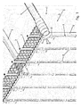
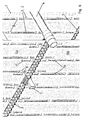
- FIG. 1 shows a perspective view of a portion of a heat exchanger 1.
- the heat exchanger 1 is, for example, a flue gas heat exchanger.
- the heat exchanger 1 has, for example, a width of 2 m and a height of 12 m. Several of these heat exchangers 1 can be arranged next to one another in modular construction, so that overall widths of, for example, 10 m result.
- Heat exchanger 1, the z. B. used in flue gas desulphurisation plants of power plants are exposed to strong corrosive influences.
- the heat exchanger tubes 2 are therefore made of plastic. Preferably, it is a fluoroplastic, in particular PTFE, MFA, PFA or TFM. The plastic has a reduced rigidity due to the increased operating temperatures.
- the holding elements 3 are preferably also made of plastic and are arranged in several height levels. In one possible embodiment, the center distance between two holding elements is 24 mm.
- the holding elements 3 extend horizontally in the flow direction S of the gas flow G. They are attached to support tubes 4 and support profiles 5 which extend transversely to the flow direction S. For reasons of clarity, only a smaller number of retaining elements 3 and the heat exchanger tubes 2 has been shown. In the practical embodiment, the holding elements 3 extend in substantially greater numbers on both sides of the illustrated heat exchanger tubes 2. Also, many of the support tubes 4 and carrier profiles 5 are arranged one above the other, for example, in vertical intervals of 50 cm to 60 cm. In the context of the invention is spoken by several levels.
- At least one film element 6 is arranged in at least one plane, preferably all planes.
- the film element 6 preferably also consists of a fluoroplastic. It has a thickness of preferably 1 mm to 3 mm and dimensions of about 500 mm in height and at least 1,000 mm in length.
- the film element 6 extends in the flow direction S.
- the special feature of the film element 6 is that it is penetrated by stiffening means 7.
- the stiffening means 7 extend vertically in the image plane.
- the number of stiffening means 7 depends essentially on the extent of the film element 6.
- the lateral extent of the film element 6 must be limited in such a way that contact with the adjacent heat exchanger tubes 2 is safely excluded.
- the stiffening means 7 are formed by the heat exchanger tubes 2. This means that the stiffening means 7 themselves extend through the holding elements 3, by the same guide elements in the form of openings, which are also provided for the heat exchanger tubes 2.
- the pockets 8 are formed by two mutually parallel slots 9, 10. These slots 9, 10 extend in the flow direction S in this embodiment.
- the length of the slots 9, 10 is selected so that the film element 6 can be issued in opposite directions, so that the heat exchanger tube 2 in its function as a stiffening means 7 through the openings in Area of the slots 9, 10 can be performed.
- the film element 6 surrounds the stiffening means 7 on both sides.
- FIG. 1 shows that each stiffening means 7 passes through a plurality of successive pockets 8 in the vertical direction.
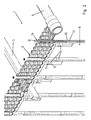
- FIG. 2 shows a further embodiment of a heat exchanger 1. It will be at FIG. 2 the too FIG. 1 introduced reference numerals used as far as identical or substantially identical components are designated.
- FIG. 2 again shows a heat exchanger 1, which differs from the design of the FIG. 1 characterized in that the stiffening means 7a are configured differently. These are not heat exchanger tubes 2, but separate stiffening means 7a in the form of struts. These stiffening means 7a do not have the function to participate in the heat exchange, but only the function tosurveyedsteifen the Fol'ienelement 6. But the stiffening elements 7a enforce also, in the same way as in FIG. 1 the heat exchanger tubes 2, the openings in the holding elements 3 in the vertical direction. The outer dimensions of the stiffening means 7a are identical except for the length. From the sectional view, however, it can be seen that the stiffening means 7a has a closed end 11. Unlike the embodiment of the FIG.
- the stiffening means 7a end the FIG. 2 at the position shown. They enforce only one film element 6 completely.
- a single heat exchanger hose 2 can pass through a plurality of film elements 6 in different planes.
- the stiffening means 7a of FIG. 2 in the form of a strut has on the outside a tubular sheath 12.
- the sheath 12 surrounds an inside support profile 13.
- the support profile 13 may be a wire or a rod.
- the support profile 13 is in particular metallic and can be protected from corrosive gases on all sides by the outer casing 12.
- the sheath 12 is preferably made of the same material as the heat exchanger tubes 1, in particular of a fluoroplastic. It is preferably a weldable fluoroplastic. In which Embodiment of FIG. 2 the end 11 of the casing 12 is closed by a plug 15.
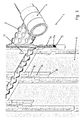
- FIG. 3 shows an alternative in which the end 11 is flattened.
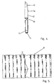
- FIG. 4 shows this embodiment in an enlarged view.
- the clipping of the upper end 11 has the advantage that the end 11 is widened.
- the diameter is larger than the diameter of the opening 12 penetrated by the sheath 12 in the holding elements 3, so that the stiffening means 7a can not slip through the holding element 3.
- the lower end 14 is closed by a plug 15.
- FIG. 3 shows how the lower ends 14 engage in pockets 8 of the film element 6. Below the pocket 8 there is a further slot 16 in the flow direction S of the gas G. As a result, the film element 6 can issue laterally transversely to the flow direction up to the slot 16 and conform to the tubular stiffening means 7a.
- FIG. 5 shows a possible embodiment of a film element 6 in a side view.
- the pockets 8 In the upper area are recesses for the support tube 4 and the support section 5, as shown in the FIGS. 1 and 2 is shown.
- An essential feature of the film element 6 are the pockets 8, several of which are arranged successively in the vertical direction.
- a further pocket 8 is additionally provided in each case. This pocket 8 is offset from the former pockets 8. It serves to receive the lower ends 11 of stiffening means, which hold another film element 6 in an overlying plane.
- FIG. 6 Finally, a variant showing a combination of the embodiments of FIGS. 1 and 2 represents.
- the stiffening means 7a are configured as struts which extend only between two successive holding elements 3. As described above, enforce the Stiffening means 7a actually provided for the heat exchanger tubes 2 openings in the holding elements 3.
- the stiffening means 7a terminate shortly above or just below the respective holding elements 3, so that the respective limited by the holding elements 3 level is completely penetrated and held the film element 6a and stiffened becomes.
- stiffening means 7 are not separate struts, but are formed by the heat exchanger tubes 2 themselves.
- the heat exchanger tubes 2 in turn extend through the pockets 8. It is therefore possible within the scope of the invention to combine different stiffening means 7, 7a in a heat exchanger with one another.
- the two variants have in common that the film element 6 is arranged substantially in the predetermined by the holding elements 3 level for the heat exchanger tubes 2 and stiffening means 7, 7a.
- the stiffening means 7, 7a By welding the film elements 6, 6a with the stiffening means 7, 7a, in particular in the central region between two holding elements 3, that is in a range corresponding to about 40% to 60% of the distance between two holding elements 3, it can be achieved that the film element 6, 6a upwards and downwards, that is evenly, expands and thus stresses within the film element 6, 6a are avoided.
- the number of stiffening means 7, 7a limits the lateral deflection of the film elements 6, 6a by thermal expansion.
- FIG. 6 shows, moreover, that the holding elements 3 can be arranged on both sides of the film element 6a or the heat exchanger tubes 2 in the holding elements 3 can accordingly run on both sides of the film element 6a. Also conceivable is a configuration in which the Heat exchanger hoses 2 are arranged only on one side of the film element 6, as for example in the FIGS. 1 and 2 can be seen.
Landscapes
- Engineering & Computer Science (AREA)
- Physics & Mathematics (AREA)
- Thermal Sciences (AREA)
- Mechanical Engineering (AREA)
- General Engineering & Computer Science (AREA)
- Heat-Exchange Devices With Radiators And Conduit Assemblies (AREA)
Priority Applications (1)
| Application Number | Priority Date | Filing Date | Title |
|---|---|---|---|
| PL14154492T PL2803929T3 (pl) | 2013-05-14 | 2014-02-10 | Wymiennik ciepła z wężami wymiennika ciepła z tworzywa sztucznego |
Applications Claiming Priority (1)
| Application Number | Priority Date | Filing Date | Title |
|---|---|---|---|
| DE102013104960 | 2013-05-14 |
Publications (3)
| Publication Number | Publication Date |
|---|---|
| EP2803929A2 EP2803929A2 (de) | 2014-11-19 |
| EP2803929A3 EP2803929A3 (de) | 2015-05-06 |
| EP2803929B1 true EP2803929B1 (de) | 2016-02-10 |
Family
ID=50072947
Family Applications (1)
| Application Number | Title | Priority Date | Filing Date |
|---|---|---|---|
| EP14154492.4A Active EP2803929B1 (de) | 2013-05-14 | 2014-02-10 | Wärmetauscher mit Wärmetauscherschläuchen aus Kunststoff |
Country Status (2)
| Country | Link |
|---|---|
| EP (1) | EP2803929B1 (pl) |
| PL (1) | PL2803929T3 (pl) |
Families Citing this family (1)
| Publication number | Priority date | Publication date | Assignee | Title |
|---|---|---|---|---|
| US11331593B2 (en) * | 2019-06-07 | 2022-05-17 | Stamicarbon B.V. | Urea plant with stripper and stripping method |
Family Cites Families (6)
| Publication number | Priority date | Publication date | Assignee | Title |
|---|---|---|---|---|
| US3263654A (en) * | 1964-06-17 | 1966-08-02 | Combustion Eng | Apparatus for eliminating destructive, self-excited vibrations in steam generators |
| US5058664A (en) * | 1990-07-13 | 1991-10-22 | Phillips Petroleum Company | Rodbaffle heat exchanger |
| GB9211413D0 (en) * | 1992-05-29 | 1992-07-15 | Cesaroni Anthony Joseph | Panel heat exchanger formed from tubes and sheets |
| DE102005012868B3 (de) * | 2003-09-18 | 2006-03-02 | Plasticon Germany Gmbh | Halte- und Führungseinrichtung für Wärmetauscherelemente |
| DE202006012164U1 (de) * | 2006-08-07 | 2006-10-12 | Babcock Borsig Service Gmbh | Abstandshalter für Wärmetauscher |
| DE102007017564A1 (de) * | 2007-04-12 | 2008-10-16 | Wallstein Ingenieur-Gesellschaft Mbh | Vorrichtung zur Distanzierung von Wärmetauscherrohren |
-
2014
- 2014-02-10 EP EP14154492.4A patent/EP2803929B1/de active Active
- 2014-02-10 PL PL14154492T patent/PL2803929T3/pl unknown
Also Published As
| Publication number | Publication date |
|---|---|
| EP2803929A2 (de) | 2014-11-19 |
| EP2803929A3 (de) | 2015-05-06 |
| PL2803929T3 (pl) | 2016-06-30 |
Similar Documents
| Publication | Publication Date | Title |
|---|---|---|
| DE102007026817B3 (de) | Kraftstoffbehälter für Kraftfahrzeuge | |
| DE3514379C2 (pl) | ||
| DE1997149U (de) | Vorrichtung zum verhindern von schwingungen in einem buendel oder in einer lage paralleler rohre | |
| DE102005029738A1 (de) | Energieabsorberelement und dieses verwendende Kraftfahrzeugkarosserie | |
| EP2547977B1 (de) | Wärmetauscher mit halteelement | |
| DE112016004865T5 (de) | Stossdämpfungsstruktur eines kraftfahrzeugs | |
| EP3106642B1 (de) | Abgasschalldämpfer zum quereinbau in ein fahrzeug | |
| EP3395598A1 (de) | Kraftstoffbehälter | |
| EP2803929B1 (de) | Wärmetauscher mit Wärmetauscherschläuchen aus Kunststoff | |
| EP1980812B1 (de) | Wärmetauscher mit Vorrichtung zur Distanzierung von Wärmetauscherrohren | |
| DE69810221T2 (de) | Stützsystem für Rohrleitungen in technischen Anlagen, insbesondere in der Nuklearindustrie | |
| DE102006034274B4 (de) | Massendurchflußmeßgerät | |
| DE19529227C2 (de) | Speicherblock für Regenerativ-Wärmetauscher | |
| DE112004000700B4 (de) | Palettencontainer mit gekreuzten Rohrstäben | |
| EP3037109B1 (de) | Behälterzellenträger zum tragen mindestens einer behälterzelle und reinigungsmaschine | |
| EP0692585B1 (de) | Schalungselement | |
| DE112015000044T5 (de) | Struktur eines Front-Längsträgers | |
| EP4169610B1 (de) | Tragrost für füllkörperpackungen | |
| DE2721653C2 (de) | Vorrichtung für die Wetterkühlung im Untertagebergbau mit an Ausbaueinheiten anbringbaren Kühlmittelträgern | |
| EP2489831A2 (de) | Tübbing mit Wärmekollektor | |
| EP3511641B1 (de) | Schalldämpfelement für eine raumlufttechnische klima- und/oder lüftungsanlage | |
| DE19526623C2 (de) | Wärmetauscher | |
| EP2256756B1 (de) | Elektrischer Transformator oder elektrische Drosselspule | |
| EP2009183B1 (de) | Schalungselement | |
| DE3628183C2 (de) | Wärmeaustauscher für den Untertagebetrieb, insbesondere Wetterkühler |
Legal Events
| Date | Code | Title | Description |
|---|---|---|---|
| PUAI | Public reference made under article 153(3) epc to a published international application that has entered the european phase |
Free format text: ORIGINAL CODE: 0009012 |
|
| 17P | Request for examination filed |
Effective date: 20140210 |
|
| AK | Designated contracting states |
Kind code of ref document: A2 Designated state(s): AL AT BE BG CH CY CZ DE DK EE ES FI FR GB GR HR HU IE IS IT LI LT LU LV MC MK MT NL NO PL PT RO RS SE SI SK SM TR |
|
| AX | Request for extension of the european patent |
Extension state: BA ME |
|
| PUAL | Search report despatched |
Free format text: ORIGINAL CODE: 0009013 |
|
| AK | Designated contracting states |
Kind code of ref document: A3 Designated state(s): AL AT BE BG CH CY CZ DE DK EE ES FI FR GB GR HR HU IE IS IT LI LT LU LV MC MK MT NL NO PL PT RO RS SE SI SK SM TR |
|
| AX | Request for extension of the european patent |
Extension state: BA ME |
|
| RIC1 | Information provided on ipc code assigned before grant |
Ipc: F28F 9/22 20060101ALI20150330BHEP Ipc: F28F 9/013 20060101ALI20150330BHEP Ipc: F28F 9/00 20060101ALI20150330BHEP Ipc: F28D 21/00 20060101ALI20150330BHEP Ipc: F28F 21/06 20060101ALI20150330BHEP Ipc: F28D 7/16 20060101AFI20150330BHEP |
|
| R17P | Request for examination filed (corrected) |
Effective date: 20150421 |
|
| GRAP | Despatch of communication of intention to grant a patent |
Free format text: ORIGINAL CODE: EPIDOSNIGR1 |
|
| INTG | Intention to grant announced |
Effective date: 20150909 |
|
| RAP1 | Party data changed (applicant data changed or rights of an application transferred) |
Owner name: WALLSTEIN INGENIEUR GMBH |
|
| GRAS | Grant fee paid |
Free format text: ORIGINAL CODE: EPIDOSNIGR3 |
|
| GRAA | (expected) grant |
Free format text: ORIGINAL CODE: 0009210 |
|
| AK | Designated contracting states |
Kind code of ref document: B1 Designated state(s): AL AT BE BG CH CY CZ DE DK EE ES FI FR GB GR HR HU IE IS IT LI LT LU LV MC MK MT NL NO PL PT RO RS SE SI SK SM TR |
|
| REG | Reference to a national code |
Ref country code: GB Ref legal event code: FG4D Free format text: NOT ENGLISH |
|
| REG | Reference to a national code |
Ref country code: AT Ref legal event code: REF Ref document number: 774860 Country of ref document: AT Kind code of ref document: T Effective date: 20160215 Ref country code: CH Ref legal event code: EP |
|
| REG | Reference to a national code |
Ref country code: IE Ref legal event code: FG4D Free format text: LANGUAGE OF EP DOCUMENT: GERMAN |
|
| REG | Reference to a national code |
Ref country code: DE Ref legal event code: R096 Ref document number: 502014000355 Country of ref document: DE |
|
| REG | Reference to a national code |
Ref country code: LT Ref legal event code: MG4D |
|
| REG | Reference to a national code |
Ref country code: NL Ref legal event code: MP Effective date: 20160210 |
|
| REG | Reference to a national code |
Ref country code: GR Ref legal event code: EP Ref document number: 20160400396 Country of ref document: GR Effective date: 20160505 |
|
| PG25 | Lapsed in a contracting state [announced via postgrant information from national office to epo] |
Ref country code: FI Free format text: LAPSE BECAUSE OF FAILURE TO SUBMIT A TRANSLATION OF THE DESCRIPTION OR TO PAY THE FEE WITHIN THE PRESCRIBED TIME-LIMIT Effective date: 20160210 Ref country code: HR Free format text: LAPSE BECAUSE OF FAILURE TO SUBMIT A TRANSLATION OF THE DESCRIPTION OR TO PAY THE FEE WITHIN THE PRESCRIBED TIME-LIMIT Effective date: 20160210 Ref country code: ES Free format text: LAPSE BECAUSE OF FAILURE TO SUBMIT A TRANSLATION OF THE DESCRIPTION OR TO PAY THE FEE WITHIN THE PRESCRIBED TIME-LIMIT Effective date: 20160210 Ref country code: NO Free format text: LAPSE BECAUSE OF FAILURE TO SUBMIT A TRANSLATION OF THE DESCRIPTION OR TO PAY THE FEE WITHIN THE PRESCRIBED TIME-LIMIT Effective date: 20160510 |
|
| PG25 | Lapsed in a contracting state [announced via postgrant information from national office to epo] |
Ref country code: NL Free format text: LAPSE BECAUSE OF FAILURE TO SUBMIT A TRANSLATION OF THE DESCRIPTION OR TO PAY THE FEE WITHIN THE PRESCRIBED TIME-LIMIT Effective date: 20160210 Ref country code: PT Free format text: LAPSE BECAUSE OF FAILURE TO SUBMIT A TRANSLATION OF THE DESCRIPTION OR TO PAY THE FEE WITHIN THE PRESCRIBED TIME-LIMIT Effective date: 20160613 Ref country code: SE Free format text: LAPSE BECAUSE OF FAILURE TO SUBMIT A TRANSLATION OF THE DESCRIPTION OR TO PAY THE FEE WITHIN THE PRESCRIBED TIME-LIMIT Effective date: 20160210 Ref country code: RS Free format text: LAPSE BECAUSE OF FAILURE TO SUBMIT A TRANSLATION OF THE DESCRIPTION OR TO PAY THE FEE WITHIN THE PRESCRIBED TIME-LIMIT Effective date: 20160210 Ref country code: LV Free format text: LAPSE BECAUSE OF FAILURE TO SUBMIT A TRANSLATION OF THE DESCRIPTION OR TO PAY THE FEE WITHIN THE PRESCRIBED TIME-LIMIT Effective date: 20160210 Ref country code: LT Free format text: LAPSE BECAUSE OF FAILURE TO SUBMIT A TRANSLATION OF THE DESCRIPTION OR TO PAY THE FEE WITHIN THE PRESCRIBED TIME-LIMIT Effective date: 20160210 Ref country code: BE Free format text: LAPSE BECAUSE OF NON-PAYMENT OF DUE FEES Effective date: 20160229 Ref country code: IS Free format text: LAPSE BECAUSE OF FAILURE TO SUBMIT A TRANSLATION OF THE DESCRIPTION OR TO PAY THE FEE WITHIN THE PRESCRIBED TIME-LIMIT Effective date: 20160610 |
|
| PG25 | Lapsed in a contracting state [announced via postgrant information from national office to epo] |
Ref country code: DK Free format text: LAPSE BECAUSE OF FAILURE TO SUBMIT A TRANSLATION OF THE DESCRIPTION OR TO PAY THE FEE WITHIN THE PRESCRIBED TIME-LIMIT Effective date: 20160210 Ref country code: EE Free format text: LAPSE BECAUSE OF FAILURE TO SUBMIT A TRANSLATION OF THE DESCRIPTION OR TO PAY THE FEE WITHIN THE PRESCRIBED TIME-LIMIT Effective date: 20160210 |
|
| REG | Reference to a national code |
Ref country code: DE Ref legal event code: R097 Ref document number: 502014000355 Country of ref document: DE |
|
| PG25 | Lapsed in a contracting state [announced via postgrant information from national office to epo] |
Ref country code: SM Free format text: LAPSE BECAUSE OF FAILURE TO SUBMIT A TRANSLATION OF THE DESCRIPTION OR TO PAY THE FEE WITHIN THE PRESCRIBED TIME-LIMIT Effective date: 20160210 Ref country code: SK Free format text: LAPSE BECAUSE OF FAILURE TO SUBMIT A TRANSLATION OF THE DESCRIPTION OR TO PAY THE FEE WITHIN THE PRESCRIBED TIME-LIMIT Effective date: 20160210 Ref country code: CZ Free format text: LAPSE BECAUSE OF FAILURE TO SUBMIT A TRANSLATION OF THE DESCRIPTION OR TO PAY THE FEE WITHIN THE PRESCRIBED TIME-LIMIT Effective date: 20160210 Ref country code: RO Free format text: LAPSE BECAUSE OF FAILURE TO SUBMIT A TRANSLATION OF THE DESCRIPTION OR TO PAY THE FEE WITHIN THE PRESCRIBED TIME-LIMIT Effective date: 20160210 |
|
| REG | Reference to a national code |
Ref country code: IE Ref legal event code: MM4A |
|
| PLBE | No opposition filed within time limit |
Free format text: ORIGINAL CODE: 0009261 |
|
| STAA | Information on the status of an ep patent application or granted ep patent |
Free format text: STATUS: NO OPPOSITION FILED WITHIN TIME LIMIT |
|
| 26N | No opposition filed |
Effective date: 20161111 |
|
| PG25 | Lapsed in a contracting state [announced via postgrant information from national office to epo] |
Ref country code: IE Free format text: LAPSE BECAUSE OF NON-PAYMENT OF DUE FEES Effective date: 20160210 |
|
| REG | Reference to a national code |
Ref country code: FR Ref legal event code: ST Effective date: 20170102 |
|
| PG25 | Lapsed in a contracting state [announced via postgrant information from national office to epo] |
Ref country code: SI Free format text: LAPSE BECAUSE OF FAILURE TO SUBMIT A TRANSLATION OF THE DESCRIPTION OR TO PAY THE FEE WITHIN THE PRESCRIBED TIME-LIMIT Effective date: 20160210 Ref country code: BG Free format text: LAPSE BECAUSE OF FAILURE TO SUBMIT A TRANSLATION OF THE DESCRIPTION OR TO PAY THE FEE WITHIN THE PRESCRIBED TIME-LIMIT Effective date: 20160510 |
|
| PG25 | Lapsed in a contracting state [announced via postgrant information from national office to epo] |
Ref country code: FR Free format text: LAPSE BECAUSE OF NON-PAYMENT OF DUE FEES Effective date: 20160411 |
|
| PG25 | Lapsed in a contracting state [announced via postgrant information from national office to epo] |
Ref country code: MT Free format text: LAPSE BECAUSE OF FAILURE TO SUBMIT A TRANSLATION OF THE DESCRIPTION OR TO PAY THE FEE WITHIN THE PRESCRIBED TIME-LIMIT Effective date: 20160210 |
|
| PG25 | Lapsed in a contracting state [announced via postgrant information from national office to epo] |
Ref country code: MC Free format text: LAPSE BECAUSE OF FAILURE TO SUBMIT A TRANSLATION OF THE DESCRIPTION OR TO PAY THE FEE WITHIN THE PRESCRIBED TIME-LIMIT Effective date: 20160210 |
|
| REG | Reference to a national code |
Ref country code: CH Ref legal event code: PL |
|
| PG25 | Lapsed in a contracting state [announced via postgrant information from national office to epo] |
Ref country code: CH Free format text: LAPSE BECAUSE OF NON-PAYMENT OF DUE FEES Effective date: 20170228 Ref country code: LI Free format text: LAPSE BECAUSE OF NON-PAYMENT OF DUE FEES Effective date: 20170228 |
|
| PG25 | Lapsed in a contracting state [announced via postgrant information from national office to epo] |
Ref country code: HU Free format text: LAPSE BECAUSE OF FAILURE TO SUBMIT A TRANSLATION OF THE DESCRIPTION OR TO PAY THE FEE WITHIN THE PRESCRIBED TIME-LIMIT; INVALID AB INITIO Effective date: 20140210 |
|
| PG25 | Lapsed in a contracting state [announced via postgrant information from national office to epo] |
Ref country code: CY Free format text: LAPSE BECAUSE OF FAILURE TO SUBMIT A TRANSLATION OF THE DESCRIPTION OR TO PAY THE FEE WITHIN THE PRESCRIBED TIME-LIMIT Effective date: 20160210 Ref country code: MK Free format text: LAPSE BECAUSE OF FAILURE TO SUBMIT A TRANSLATION OF THE DESCRIPTION OR TO PAY THE FEE WITHIN THE PRESCRIBED TIME-LIMIT Effective date: 20160210 Ref country code: LU Free format text: LAPSE BECAUSE OF NON-PAYMENT OF DUE FEES Effective date: 20160210 |
|
| GBPC | Gb: european patent ceased through non-payment of renewal fee |
Effective date: 20180210 |
|
| PG25 | Lapsed in a contracting state [announced via postgrant information from national office to epo] |
Ref country code: AL Free format text: LAPSE BECAUSE OF FAILURE TO SUBMIT A TRANSLATION OF THE DESCRIPTION OR TO PAY THE FEE WITHIN THE PRESCRIBED TIME-LIMIT Effective date: 20160210 |
|
| PG25 | Lapsed in a contracting state [announced via postgrant information from national office to epo] |
Ref country code: GB Free format text: LAPSE BECAUSE OF NON-PAYMENT OF DUE FEES Effective date: 20180210 |
|
| PGFP | Annual fee paid to national office [announced via postgrant information from national office to epo] |
Ref country code: ES Payment date: 20181203 Year of fee payment: 15 |
|
| PGFP | Annual fee paid to national office [announced via postgrant information from national office to epo] |
Ref country code: TR Payment date: 20190313 Year of fee payment: 6 Ref country code: GR Payment date: 20190301 Year of fee payment: 6 |
|
| REG | Reference to a national code |
Ref country code: AT Ref legal event code: MM01 Ref document number: 774860 Country of ref document: AT Kind code of ref document: T Effective date: 20190210 |
|
| PG25 | Lapsed in a contracting state [announced via postgrant information from national office to epo] |
Ref country code: AT Free format text: LAPSE BECAUSE OF NON-PAYMENT OF DUE FEES Effective date: 20190210 |
|
| PG25 | Lapsed in a contracting state [announced via postgrant information from national office to epo] |
Ref country code: GR Free format text: LAPSE BECAUSE OF NON-PAYMENT OF DUE FEES Effective date: 20200909 |
|
| PG25 | Lapsed in a contracting state [announced via postgrant information from national office to epo] |
Ref country code: IT Free format text: LAPSE BECAUSE OF NON-PAYMENT OF DUE FEES Effective date: 20200210 |
|
| PG25 | Lapsed in a contracting state [announced via postgrant information from national office to epo] |
Ref country code: TR Free format text: LAPSE BECAUSE OF NON-PAYMENT OF DUE FEES Effective date: 20200210 |
|
| PGFP | Annual fee paid to national office [announced via postgrant information from national office to epo] |
Ref country code: DE Payment date: 20250220 Year of fee payment: 12 |
|
| PGFP | Annual fee paid to national office [announced via postgrant information from national office to epo] |
Ref country code: PL Payment date: 20250131 Year of fee payment: 12 |