EP2803908B1 - Lamp module - Google Patents
Lamp module Download PDFInfo
- Publication number
- EP2803908B1 EP2803908B1 EP14164534.1A EP14164534A EP2803908B1 EP 2803908 B1 EP2803908 B1 EP 2803908B1 EP 14164534 A EP14164534 A EP 14164534A EP 2803908 B1 EP2803908 B1 EP 2803908B1
- Authority
- EP
- European Patent Office
- Prior art keywords
- lamp
- module
- lamp module
- luminaire
- cross bars
- Prior art date
- Legal status (The legal status is an assumption and is not a legal conclusion. Google has not performed a legal analysis and makes no representation as to the accuracy of the status listed.)
- Active
Links
Images

Classifications
-
- F—MECHANICAL ENGINEERING; LIGHTING; HEATING; WEAPONS; BLASTING
- F21—LIGHTING
- F21V—FUNCTIONAL FEATURES OR DETAILS OF LIGHTING DEVICES OR SYSTEMS THEREOF; STRUCTURAL COMBINATIONS OF LIGHTING DEVICES WITH OTHER ARTICLES, NOT OTHERWISE PROVIDED FOR
- F21V19/00—Fastening of light sources or lamp holders
- F21V19/001—Fastening of light sources or lamp holders the light sources being semiconductors devices, e.g. LEDs
- F21V19/003—Fastening of light source holders, e.g. of circuit boards or substrates holding light sources
- F21V19/004—Fastening of light source holders, e.g. of circuit boards or substrates holding light sources by deformation of parts or snap action mountings, e.g. using clips
-
- F—MECHANICAL ENGINEERING; LIGHTING; HEATING; WEAPONS; BLASTING
- F21—LIGHTING
- F21S—NON-PORTABLE LIGHTING DEVICES; SYSTEMS THEREOF; VEHICLE LIGHTING DEVICES SPECIALLY ADAPTED FOR VEHICLE EXTERIORS
- F21S4/00—Lighting devices or systems using a string or strip of light sources
- F21S4/20—Lighting devices or systems using a string or strip of light sources with light sources held by or within elongate supports
- F21S4/28—Lighting devices or systems using a string or strip of light sources with light sources held by or within elongate supports rigid, e.g. LED bars
-
- F—MECHANICAL ENGINEERING; LIGHTING; HEATING; WEAPONS; BLASTING
- F21—LIGHTING
- F21V—FUNCTIONAL FEATURES OR DETAILS OF LIGHTING DEVICES OR SYSTEMS THEREOF; STRUCTURAL COMBINATIONS OF LIGHTING DEVICES WITH OTHER ARTICLES, NOT OTHERWISE PROVIDED FOR
- F21V17/00—Fastening of component parts of lighting devices, e.g. shades, globes, refractors, reflectors, filters, screens, grids or protective cages
- F21V17/10—Fastening of component parts of lighting devices, e.g. shades, globes, refractors, reflectors, filters, screens, grids or protective cages characterised by specific fastening means or way of fastening
- F21V17/104—Fastening of component parts of lighting devices, e.g. shades, globes, refractors, reflectors, filters, screens, grids or protective cages characterised by specific fastening means or way of fastening using feather joints, e.g. tongues and grooves, with or without friction
-
- F—MECHANICAL ENGINEERING; LIGHTING; HEATING; WEAPONS; BLASTING
- F21—LIGHTING
- F21V—FUNCTIONAL FEATURES OR DETAILS OF LIGHTING DEVICES OR SYSTEMS THEREOF; STRUCTURAL COMBINATIONS OF LIGHTING DEVICES WITH OTHER ARTICLES, NOT OTHERWISE PROVIDED FOR
- F21V19/00—Fastening of light sources or lamp holders
- F21V19/001—Fastening of light sources or lamp holders the light sources being semiconductors devices, e.g. LEDs
- F21V19/003—Fastening of light source holders, e.g. of circuit boards or substrates holding light sources
- F21V19/0035—Fastening of light source holders, e.g. of circuit boards or substrates holding light sources the fastening means being capable of simultaneously attaching of an other part, e.g. a housing portion or an optical component
-
- F—MECHANICAL ENGINEERING; LIGHTING; HEATING; WEAPONS; BLASTING
- F21—LIGHTING
- F21V—FUNCTIONAL FEATURES OR DETAILS OF LIGHTING DEVICES OR SYSTEMS THEREOF; STRUCTURAL COMBINATIONS OF LIGHTING DEVICES WITH OTHER ARTICLES, NOT OTHERWISE PROVIDED FOR
- F21V19/00—Fastening of light sources or lamp holders
- F21V19/001—Fastening of light sources or lamp holders the light sources being semiconductors devices, e.g. LEDs
- F21V19/003—Fastening of light source holders, e.g. of circuit boards or substrates holding light sources
- F21V19/0045—Fastening of light source holders, e.g. of circuit boards or substrates holding light sources by tongue and groove connections, e.g. dovetail interlocking means fixed by sliding
-
- F—MECHANICAL ENGINEERING; LIGHTING; HEATING; WEAPONS; BLASTING
- F21—LIGHTING
- F21Y—INDEXING SCHEME ASSOCIATED WITH SUBCLASSES F21K, F21L, F21S and F21V, RELATING TO THE FORM OR THE KIND OF THE LIGHT SOURCES OR OF THE COLOUR OF THE LIGHT EMITTED
- F21Y2103/00—Elongate light sources, e.g. fluorescent tubes
- F21Y2103/10—Elongate light sources, e.g. fluorescent tubes comprising a linear array of point-like light-generating elements
-
- F—MECHANICAL ENGINEERING; LIGHTING; HEATING; WEAPONS; BLASTING
- F21—LIGHTING
- F21Y—INDEXING SCHEME ASSOCIATED WITH SUBCLASSES F21K, F21L, F21S and F21V, RELATING TO THE FORM OR THE KIND OF THE LIGHT SOURCES OR OF THE COLOUR OF THE LIGHT EMITTED
- F21Y2115/00—Light-generating elements of semiconductor light sources
- F21Y2115/10—Light-emitting diodes [LED]
Definitions
- the invention relates to a luminaire module for holding at least one luminaire element for mounting and fixing the luminaire element in a luminaire.
- a generic lighting module is from the EP 2 557 359 known.
- Such conventional luminaires comprise a luminaire housing, in which luminaire elements, such as lamps or optical elements, are mounted and fixed. This is usually done by screwing the lamp elements with the lamp housing.
- luminaire elements such as lamps or optical elements
- boards with LEDs are often used as lighting means, being screwed by holes provided in the board screws with a thread on the lamp housing for fixing the board.
- optical elements for generating a certain radiation characteristics of the lamp are often mounted in the luminaire housing by screws or clamps that the lamps provided in the lamp housing can emit light through the optical element, so that the desired radiation characteristic of the lamp by the relative arrangement of optical element and light source is guaranteed.
- a first approach for such a modular design is to provide self-contained modules in which lamp elements are mounted on a support unit, these finished modules can be used in large recesses in the lamp housing and bolted to the lamp housing. This has the advantages of facilitating the maintenance of the luminaire and of making the modules separate from the luminaire, making the assembly of the luminaire simpler and less expensive.
- the invention is therefore an object of the invention to provide a lamp module for holding at least one lamp element for mounting and fixing the lamp element in a luminaire, which at least partially overcomes the above-mentioned disadvantages of known modules and can contribute to a simple, inexpensive and easy to maintain construction of a lamp ,
- the stated object is achieved by providing a luminaire module which comprises two longitudinal side by side, in particular parallel side walls, which are interconnected by transversely extending transverse webs, wherein the side walls are vertical to that of the longitudinal direction and the transverse direction extend defined level.
- the side walls do not necessarily have to run continuously in the longitudinal direction of the luminaire module.
- the side walls can also be represented by side wall elements arranged side by side in the longitudinal direction and spaced from one another, which are connected to one another in the longitudinal direction, wherein the side wall elements can be cuboid or cylindrical, for example.
- such side wall elements are arranged linearly next to one another in a straight line, so that the side wall formed by the side wall elements runs straight in the longitudinal direction.
- the side wall elements can also be arranged next to one another in such a way that a longitudinally curved profile of the side wall formed by the side wall elements results. Accordingly, a continuously formed side wall in the longitudinal direction can run straight or curved.
- a straight course of the side wall can bring the advantage that a lamp element is particularly easy to insert between the side walls.
- a curved course of a side wall can have the advantage bring themselves that a inserted between the side walls lamp element is particularly well managed.
- the course of the two side walls in one exemplary embodiment does not necessarily have to be identical.
- the course of the side walls in the longitudinal direction is identical.
- At least one lateral web is arranged, which extends in the transverse direction and vertically from the transverse webs, d. H. vertical to the plane defined by the longitudinal direction and the transverse direction.
- the lateral web does not necessarily have to run continuously over the longitudinal extent of the luminaire module.
- the web may comprise longitudinally spaced-apart web elements.
- the transverse webs, the side walls and the at least one lateral web or the lateral webs are arranged to each other so that they comprise a gap at least in sections, in which the lamp element is inserted in the longitudinal direction, wherein the gap has planar openings between the transverse webs are arranged.
- the at least one lateral web has a holding element for holding the lamp element, which is resilient in the direction of the transverse webs and for generating a contact pressure on the lamp element to the transverse webs, wherein a fixing element, in particular on the at least one lateral web, vertically spaced from the transverse webs is provided for holding the lamp element, wherein the fixing element is resilient in the direction of the transverse webs, wherein the fixing element is further removed from the side wall on which the lateral web is arranged, as the holding element.
- the luminaire module according to the invention is designed so that a lamp element to be held in the intermediate space may possibly be held in pressure contact between the holding element and transverse webs in the luminaire module.
- the holding element can exert a contact pressure on him nearest lamp element, the contact pressure of this lamp element at least partially to at least one of the other Luminaire elements for holding the at least one further luminaire element can be passed.
- the holding element can exert on the space to be held in the space lamp element or arranged in the space lamp elements a contact pressure against a force exerted externally by the surface openings vertically on the lamp module force, whereby the lamp module can be pressed against a force generating device this device ,
- the holding element can be designed differently.
- the holding element can be formed continuously in the longitudinal direction or else also comprise holding element sections which are spaced apart from one another in the longitudinal direction.
- the holding element can be arranged as an additional component on the lateral web.
- the retaining element may be formed integrally with the lateral web.
- the holding element can be realized by the shape of the lateral web itself.
- the holding element can be realized for example by the side facing the transverse webs side of the web page.
- the lateral web may have a corresponding profiling, which represents the holding element.
- the holding element several, in particular in the longitudinal direction comprise spaced apart, integrated in the web bending springs.
- the bending springs can thus represent the holding element sections.
- such bending springs may be integrally formed with the web, for example by integrated into the web, hook-like projections which are elastic to the web.
- the intermediate space is not enclosed by the transverse webs, the side walls and the at least one lateral web. Rather, the gap on planar openings, which are arranged between the transverse webs.
- the planar openings may be defined by the transverse webs and the side walls, so that the planar openings between two adjacent transverse webs and the side walls are closed in a flat manner.
- the areal openings are formed so large that the surface occupied jointly by the entire areal openings of the luminaire module make up a substantial portion of the cross section of the luminaire module in the plane defined by the longitudinal direction and the transverse direction, in particular a proportion of more than 50% of this cross section , in particular a proportion of more than 70%, in particular a proportion of more than 90% of this cross section.
- the luminaire module according to the invention has the advantage that luminaire elements can be introduced into the luminaire module in a particularly simple manner and held in the luminaire module.
- associated lighting elements without additional fixation measures are required to be inserted laterally into the gap of the lamp module, wherein a sufficient holding force for holding the lamp element is ensured in the lamp module by the interaction of transverse webs and retaining element.
- the transverse webs give the lamp module according to the invention a sufficient Stability.
- the lamp module As a result, a particularly high stability of the lamp module is required for a reliable and durable installation of a lamp element by means of the lamp module in a lamp housing, as brought in a fixation of the lamp module with a lamp module arranged in the lamp element, the lamp element on the flat openings in direct contact with the lamp housing can be.
- the lamp element when the lamp element is designed as a board with LEDs, a cooling contact between the lamp housing and lamp element can be ensured on the surface openings. For this purpose, in particular the provision of correspondingly large area openings may be advantageous.
- the luminaire module according to the invention further comprises, in particular on the lateral web, a fixing element for holding a lamp element, wherein the fixing element is vertically spaced from the transverse webs and is resilient in the direction of the transverse webs.
- the fixing element may be arranged, for example, on a further lateral web or directly on the side wall.
- the fixing element like the retaining element also allows the fixing thus a reliable holding of the lamp element in the Interspace, by being able to generate a contact pressure on the lamp element to the transverse webs out.
- the lighting element between fixing and transverse bars can be maintained.
- the fixing can be formed continuously or interrupted in the longitudinal direction. For example, a luminaire element can be held in the luminaire module at the same time by fixing element and retaining element.
- the holding element holds a first luminaire element and the fixing element holds a second luminaire element.
- two lamp elements may be provided in the lamp module, which are arranged one above the other, wherein the holding element can exert a contact pressure on the first lamp element for holding the first lamp element, and wherein the fixing element can exert a contact pressure on the second lamp element, whereby the second lamp element on the first lamp element and on the transverse webs or, for example, on a protruding through the planar openings in the intermediate device to which the lamp module is attached, may be pressed.
- the fixing element is further removed from the side wall, on which the lateral web is arranged, as the holding element.
- This can be ensured, for example, holding a lamp element in the lamp module, in which the holding element exerts a contact pressure on the lamp element close to the side wall and the fixing near the transverse center of the lamp module exerts a contact pressure on the lamp element, so that the lamp element evenly by holding element and Fixing a contact pressure, for example, learns on the transverse webs.
- a first lamp element can be pressed by the closer to the side wall holding member to the transverse webs, while a second lamp element by the fixing is pressed closer to the transverse center of the lamp module to the transverse webs.
- the corresponding arrangement may also be advantageous if the fixing element exerts a contact pressure on a second lamp element and also on a first lamp element, wherein the lamp element is additionally held by the holding element, so that a uniform contact pressure is ensured to the transverse webs.
- the luminaire module according to the invention thus enables a reliable fixation of the luminaire element or the luminaire elements by the guidance and holding of a luminaire element or the luminaire elements and can be produced particularly cost-effectively because of its fiction-specific structure, since no particularly high demands are placed on the stability of the luminaire module have to.
- the luminaire module according to the invention can be designed to hold at least one standardized luminaire element. By providing standardized luminaire elements, the production of luminaires can be further simplified and discounted. For example, standard dimensions can be provided for standardized luminaire elements, which are matched to the dimensions of the luminaire module according to the invention, so that a standardized luminaire element can be held in the luminaire module.
- luminaire module thus enables on the one hand the cost-effective production of luminaires and, on the other hand, the simple replacement of luminaire elements for the maintenance of the luminaire.
- the luminaire module is integrally formed, in particular as an injection molded part.
- the luminaire module is particularly cost-effective getting produced.
- no assembly of the lamp module is required. Due to its design as a plastic, in particular as an injection molded part sufficient flexibility and stability of the lamp module is guaranteed.
- the transverse webs and the side walls are formed integrally together, in a further embodiment, the transverse webs, the side walls, the lateral webs and the holding elements, in a further embodiment, the fixing elements.
- the one-piece components may each be an injection molded part.
- each of the side walls has a lateral web.
- the two lateral webs can be formed identically in one embodiment and each comprise an identical holding element and possibly also an identical fixing element.
- the lateral webs, which are each arranged on a side wall can also have a different design, for example, a lateral web can have only one retaining element and the other lateral web holding and fixing element.
- a particularly uniform contact pressure on one or more lighting elements can be ensured.
- the fixing element is designed as a profile in the lateral web.
- the fixing element can be integrated directly in the lateral web or the lateral web directly act as a fixing.
- the fixing element may be arranged on the side wall opposite the end of the lateral web. This can be between a lamp element to be held and the fixing a Form interface over which presses the fixing element on the lamp element, which promotes in particular a slight insertion of the lamp element in the lamp module.
- fixing element and retaining element on the lateral web are so far apart from each other that they can exert a spring force on a lamp element to the transverse webs substantially independently of each other.
- the at least one lateral web is subdivided into separate longitudinal sections.
- a better elastic property of the lateral web can be ensured, which can be advantageous in particular for the spring force exerted by the fixing element and / or the retaining element on a lamp element.
- latching lugs are arranged on the side facing away from the gap side of the side walls for latching a lamp cover to the lamp module.
- the detents may be formed as recesses into which projections arranged on the lamp cover can engage.
- the locking lugs may be formed as projections which can engage in arranged on the lamp cover recesses. Projections and recesses correspond respectively.
- the transverse webs are arranged at a constant distance parallel to each other and / or each have the same geometric dimensions.
- the geometric dimensions relate to the height, length, width and / or shape of the transverse webs.
- a blocking element is provided on at least one of the side walls and / or on at least one of the transverse webs and / or at least one of the lateral webs for blocking the longitudinal mobility of at least one of the lamp elements held in the lamp module.
- a blocking element may for example be formed as a projection which forms a stop for the lamp element when inserting the lamp element into the lamp module.
- a blocking element may for example be formed as a projection which can engage in a recess or recess of a corresponding, to be inserted luminous element.
- a head piece is provided on at least one of the longitudinal ends of the lamp module, which limits the intermediate space as a boundary wall.
- the head piece can thus complete the associated longitudinal side of the lamp module.
- a head piece at one longitudinal end of the luminaire module can be formed integrally with the luminaire module, so that the head piece forms a stop for the luminaire element when a luminaire element is inserted into the luminaire module.
- such a lockable head piece may be provided at each of the two longitudinal ends of the lamp module.
- a lamp element inserted into the lamp module can be reliably secured against longitudinal displacement in the lamp module.
- head pieces can also form an optical termination, which can be advantageous in particular if a luminaire consists essentially of a luminaire module and a luminaire cover as a luminaire body in a simple manner.
- the luminaire module may further comprise a first latch unit for latching the luminaire module in a luminaire housing, wherein the latching unit may be configured such that when latched to a corresponding second latch unit disposed on the luminaire housing, it applies a force to the luminaire module with a component vertically from the lateral rib generated towards the transverse webs.
- the first latching unit may in particular comprise latching hooks.
- a particularly good fixation of a luminaire element to a luminaire housing via the interaction of the luminaire module with the luminaire housing can be ensured.
- this can also be a be made particularly good thermal contact between the lamp element and the lamp housing, so that heat from the lamp element to the lamp housing and can be dissipated to the outside.
- First latch unit and second latch unit correspond to each other.
- the first latching unit may comprise latching hooks, while the second latching unit comprises recesses.
- the first latching unit may comprise recesses, while the second latching unit comprises latching hooks.
- the locking units may comprise both recesses and latching hooks, wherein in each case a latching hook corresponds with a recess.
- end edges may be provided with which the respective latching hooks can lock.
- the latching hooks may have a cross section which tapers in sections in the direction from the lateral web to the transverse webs.
- latching hooks from which the first latching unit may be wholly or partially, extend vertically beyond the side walls at the vertical end of the side walls on which the transverse webs are arranged.
- the first latching unit comprises external latching elements.
- the second latching unit comprises external latching elements.
- the second latching unit may further comprise recesses in which external latching elements can be fixed, for example latched.
- the fixed in the recesses external locking elements can lock with the first locking unit by the external locking elements correspond to the first locking unit according to the above explained.
- the external locking elements may comprise a spring steel element.
- the invention further relates to a luminaire housing, which corresponds to a luminaire module according to the invention for receiving the luminaire module.
- the invention thus relates to a luminaire housing, which is related to a lamp module according to the invention, wherein the luminaire housing according to the invention and the luminaire module according to the invention complement each other and are designed to cooperate with each other.
- the luminaire housing according to the invention is designed such that it corresponds to a luminaire module for receiving the luminaire module, wherein the luminaire module for holding at least one standardized luminaire element for the Mounting and fixing of the lamp element is formed in a lamp, the lamp module comprising two longitudinally side by side, in particular mutually parallel side walls which are interconnected by transversely extending transverse webs, wherein the side walls are vertical to the plane defined by the longitudinal direction and the transverse direction wherein at least one lateral web is arranged on at least one of the side walls and extends transversely and is vertically spaced from the transverse webs, the transverse webs, the side walls and the lateral web being arranged relative to one another at least in sections, in which the lamp element in the longitudinal direction can be inserted, wherein the intermediate space has surface openings which are arranged between the transverse webs, wherein the lateral web has a holding element for holding the lamp element, which in the direction of the transverse webs h is formed in resilient and in particular for generating a
- the invention relates to the luminaire housing as a separate component of the lamp module, which is designed to interact with the lamp module.
- the invention relates to the combination of the luminaire housing and the luminaire module.
- the invention relates to a set comprising the luminaire housing and the luminaire module.
- the luminaire housing has receiving recesses for receiving the Transverse webs of the luminaire module.
- the luminaire housing can have a latching device, which in particular comprises latching recesses, in particular for simultaneous fixation of the luminaire module in the luminaire housing when receiving the transverse webs in the receiving recesses.
- the receiving recesses correspond to the transverse webs of the lamp module with respect to the geometric dimension, the distance of the transverse webs and the successive arrangement of the transverse webs.
- the receiving recesses have such a vertical depth that the lamp module can be arranged with the transverse webs in the receiving recesses in the lamp housing, that close the gap defining vertical ends of the transverse webs flush with a surface of the lamp housing.
- the latching device may comprise Verrastaussparungen example.
- the latching device may comprise latching hooks, for example.
- the latching device may be at least one element of the second latching unit described above, which corresponds to a first latching unit, described above, which is arranged on the luminaire module.
- the latching device comprise Verrastaussparungen, wherein the fixing of the lamp module via external latching elements, which are arranged in the Verrastaussparungen.
- the latching device may comprise latching hooks, which correspond to the fixing of the lamp module with recesses in the lamp module.
- the latching device may comprise latching recesses which correspond to latching hooks arranged on the luminaire module.
- the Verrastaussparungen can be formed, for example, as two Aussparungslinien, between which the lamp module can be arranged, wherein the receiving recesses are arranged at least partially in the transverse direction between the Verrastaussparept.
- This makes it possible, for example, a lamp module to which no latching hooks are provided on the side walls, first use the transverse webs in the receiving recesses and then via external locking elements, which are attached to the outside of the lamp module for locking with the lamp housing, with the lamp housing fix.
- This also makes it possible, for example, to lock a luminaire module with latching hooks provided on the outside of the side walls in the luminaire housing, wherein the latching can take place simultaneously with the insertion of the transverse webs into the receiving recesses.
- This can allow a particularly simple assembly of a luminaire or a luminaire module with a luminaire housing.
- the invention further comprises a circuit board which corresponds to a luminaire module according to the invention.
- the board has a width which corresponds to the distance of the side walls of the lamp module from each other, wherein the board in the lamp module between the side walls can be arranged and thereby can be guided by the side walls.
- LEDs are arranged in an LED area, wherein the LED area in the arrangement of the board according to the invention in the inventive Luminaire module in the transverse direction outside of the holding elements and in particular the fixing elements, wherein the lateral web is in the arrangement of the board in the lamp module in the transverse direction offset from the LED area.
- the board according to the invention ensures that the emission of light by the LEDs arranged on the board is not impaired by a lateral web or fixing or retaining elements.
- inventive board with inventive lamp module it is ensured by the interaction of inventive board with inventive lamp module that the board is securely held with the LEDs in the lamp module.
- the invention comprises an optical element which corresponds to a luminaire module according to the invention.
- the optical element has mounting areas, which correspond to the fixing element and / or the retaining element of the luminaire module, wherein the mounting areas extend linearly along the longitudinal extent of the optical element.
- the optical element according to the invention can thus be inserted in the longitudinal direction in the lamp module according to the invention, wherein fixing and / or holding element exert a contact force on the optical element in the direction of the transverse webs, whereby the optical element can be held in the lamp module.
- the optical element, the circuit board and the luminaire module can be formed corresponding to one another, so that the circuit board and the optical element can be inserted one above the other into the luminaire module according to the invention and can be held in the luminaire module by holding and / or fixing elements.
- the optical element may have fixing sections which are provided with fixing elements of the Luminaire module correspond.
- the optical element may have flat standing areas which, in the installation position of the optical element in the luminaire module, indicate the transverse webs and which are designed such that a flat and non-destructive contact pressure on an element, such as transverse webs or printed circuit board, can be generated by the optical element.
- a corresponding board and a corresponding optical element can be held, the board and the optical element can be held in a predefined position to each other.
- the optical element can thus be assigned predetermined on the board LEDs, so that with the choice of a particular optical element, a certain radiation characteristics of the arrangement comprising the lamp module, board and optical element can be selected.
- the optical element may for example consist of a plastic.
- the luminaire module according to the invention, the circuit board according to the invention and the optical element according to the invention are particularly suitable for series production of luminaires, wherein certain optical elements and circuit boards according to the invention can be combined with one another in a luminaire module according to the invention, so that a modular kit can be provided comprising luminaire modules, circuit boards and optical elements, wherein, depending on the lamp to be produced, a luminaire module according to the invention can be combined with a desired board according to the invention and a desired optical element according to the invention.
- the equipped lighting module can then be quickly and inexpensively, in particular automated, used in the luminaire housing and locked to the luminaire housing.
- the invention relates to a luminaire comprising a luminaire housing according to the invention.
- the invention relates to a luminaire, which further comprises a luminaire module, which is designed to hold at least one standardized luminaire element for mounting and fixing the luminaire element in a luminaire, the luminaire module comprising two side by side in the longitudinal direction, in particular mutually parallel side walls passing through transversely extending transverse webs are connected to each other, wherein the side walls extend vertically to the plane defined by the longitudinal direction and the transverse direction, wherein at least one lateral web is arranged on at least one of the side walls, which extends in the transverse direction and is vertically spaced from the transverse webs, wherein the transverse webs, the side walls and the lateral web are arranged to one another such that they comprise a gap at least in sections, in which the lamp element is inserted in the longitudinal direction, wherein the intermediate space has planar openings which are arranged between the transverse webs, wherein the lateral web has a holding element for
- the luminaire according to the invention comprises a luminaire housing according to the invention, wherein the transverse webs of the luminaire module are arranged in the receiving recesses and the luminaire module is fixed to the luminaire housing via the latching devices, wherein the latching device applies a contact pressure to the luminaire module to the luminaire housing to fix the luminaire module the luminaire housing is guaranteed.
- the locking device may be formed as an edge, are latched to the arranged on the lamp module latching hooks.
- the latching device comprise Verrastaussparept in which arranged on the lamp module latching hooks are locked.
- the latching device may comprise latching hooks which are latched to the luminaire module.
- the lamp according to the invention may also comprise a plurality of lamp elements, which are arranged in the same lamp module, wherein the lamp elements are arranged vertically one above the other in the lamp module and held by fixing and / or holding element.
- the luminaire according to the invention comprises a circuit board according to the invention as a luminaire element, wherein the circuit board is held in the luminaire module by the holding element.
- the luminaire according to the invention comprises an optical element according to the invention as a luminaire element which is held in the lamp module via the holding element or the fixing element.
- the luminaire according to the invention comprises both a circuit board according to the invention and an optical element according to the invention, wherein the circuit board according to the invention is held in the luminaire module by the holding element and, moreover, the optical element is arranged above the circuit board and is held over the fixing element, wherein the fixing element presses the optical element against the board, whereby the board is also held by the fixing element.
- the invention relates to a method for producing a luminaire according to the invention.
- a board and / or an optical element is inserted as a lamp element in a lamp module in the longitudinal direction.
- the transverse webs of the lamp module are arranged in the receiving recesses of the lamp housing and the lamp module at least with a component vertically, in particular vertically, locked to the plane defined by the longitudinal direction and the transverse direction in the lamp, thereby applying a contact pressure on the lamp element the luminaire housing is generated.
- the board and the optical element can be inserted, for example, simultaneously or one after the other in the longitudinal direction in the lamp module.
- Characterized in that the second step is carried out with the vertical latching of the lamp module after optical element and / or board were introduced into the lamp module, can be generated by the latching of the lamp module with the lamp housing, a contact pressure on the lamp elements to the lamp housing. This results in the above advantages.
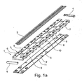
- FIG. 1a in each case an exemplary embodiment of a luminaire module 1 according to the invention, a circuit board 2 according to the invention and an optical element 3 according to the invention are shown.
- the luminaire module 1 is designed so that the side walls 7, the transverse webs 8, the lateral webs 9, the holding elements 5 and the fixing elements 6 and the latching hooks 10 are formed as a one-piece component.
- this includes in FIG. 1a shown lamp module 1 two head pieces 4, each complete a longitudinal end of the lamp module 1. While in FIG. 1a the lamp module 1, the board 2 and the optical element 3 as are shown separate components, is in FIG.
- the lamp module 1 is shown after the optical element 3 and the board 2 were inserted into the lamp module 1 in the longitudinal direction and the head pieces 4 were fixed to the longitudinal ends of the lamp module 1 by latching on the lamp module 1.
- the respectively in the FIGS. 1a and 1b shown components are identical.
- the lamp module 1 comprises two longitudinally parallel side walls 7, wherein on the side walls 7 latching hooks 10 are arranged, wherein the side walls 7 at the height of the latching hooks 10 in sections has recesses to ensure the elasticity of the latching hooks 10.
- the side walls 7 are interconnected by transverse webs 8.
- transverse webs 8 At the transverse web 8 facing away from the vertical end of the side walls 7 are each a lateral web 9 is arranged, which extends in the transverse direction.
- the lateral webs 9 do not extend from the side wall 7 to the transverse center of the lamp module 1, so that the lateral webs 9 are spaced from each other.
- the transverse webs 8, the side walls 7 and the lateral webs 9 comprise the gap in sections and not closed.
- the gap in the area in which the lateral webs 9 are spaced from each other is open.
- the gap has planar openings which are arranged between the transverse webs 8. The planar openings extend in a closed area between two adjacent transverse webs 8.
- the side walls 7 and arranged on the respective side walls 7 lateral webs 9 are each formed identically.
- the lateral webs 9 are divided into separate longitudinal sections.
- an elastic property of the side webs 9 is ensured.
- This elastic property means that the lateral webs 9 under the action of a vertical force, ie a Force acting perpendicular to the plane formed by the longitudinal extent and the transverse extent of the lamp module, can be deflected at an angle to the side walls 7.
- the lateral webs 9 each comprise a holding element 5.
- the holding element 5 is formed integrally with the associated lateral web 9 and comprises a plurality of integrated in the lateral web 9 bending springs 55.
- the torsion springs 55 are discussed below in connection with FIG. 2a explained in more detail.
- a fixing element 6 is also provided.
- the fixing element 6 is incorporated as a profile in the lateral web 9.
- the head pieces 4 locking devices with which they can be locked to the side walls 7 of the lamp module 1.
- the head pieces 4 lock the optical element 2 and the board 3 after being pushed into the intermediate space of the luminaire module 1 against movement in the longitudinal direction.
- FIG. 1a Furthermore, a circuit board 2 according to the invention with LEDs 11 is shown.
- the LEDs 11 are arranged linearly in a row.
- the corresponding optical element 3 is also linear, ie straight, so that the optical element 3 can be arranged above the LEDs 11 of the board 2 and thus can specify the emission characteristic of the LEDs 11 of the board 2.
- FIG. 1b are luminaire module 1, board 2 and optical element 3 assembled shown.
- the head pieces 4 are latched to the longitudinal ends of the lamp module 1, so that the optical element 3 and 2 board in the longitudinal direction not can move.
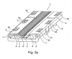
- the assembly situation of luminaire module 1, board 2 and optical element 3 is in the FIGS. 2a and 2 B shown in more detail.
- the holding elements 5 and the fixer elements 6 do not directly exert a contact pressure on the board 2 and the optical element 3 on the transverse webs 8 in the assembled state of the luminaire module 1, the board 2 and the optical element 3. Rather, a small clearance is provided between the transverse webs 8 and the board 2 in the assembled state of rest.
- retaining elements 5 and fixing elements 6 hold the optical element 3 and the board 2 in the luminaire module 1, since they limit the vertical movement of the board 2 and the optical element 3.
- the fixing elements 6 are formed as an oblique profile on the lateral webs 9. As a result, a centering of the optical element 3 is ensured in the desired position in the lamp module 1.
- the optical element 3 is arranged above the LEDs 11 of the board 2, in order to predetermine the Abstrahlchärakterizing the LEDs 11, with which the LEDs 11 can radiate through the area resulting from the distance of the lateral webs 9 from each other.
- the optical element 3 has corresponding sections to the fixing elements 6, which ensure reliable together with the fixing elements 6 of the centering of the optical element 3 in the lamp module 1.
- the optical element 3 has standing areas 33 with which the optical element 3 can rest flat on the circuit board 2. As a result, destruction of the board 2 is reliably prevented. From the FIGS.
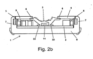
- a fixing element 6 is further away from its associated side wall 7 than the holding element 5, which is arranged on the same lateral web 9. Because of its small distance from the side wall 7, the holding element 5 experiences hardly any elastic restoring force of the lateral web 9 at a load of the holding member 5 in the vertical direction. In contrast, the fixing element 6 is arranged on the side wall 7 opposite the end of the lateral web 9, so that the lateral web 9 provides the resilient action of the fixing element 6. It is obvious that the resilient effects of the holding element 5 and the fixing element 6 are each independently of one another and that the holding element 5 and the fixing element 6 do not essentially influence each other.
- the torsion springs 55 of the retaining element 5 are integrated in the lateral web 9 and point like a hook on the transverse webs 8.
- the bending springs 55 of the holding element 5 provide a spring action per se.
- retaining elements 5 and fixing elements 6 in the assembled idle state of luminaire module 1, circuit board 2 and optical element 3 do not exert any contact pressure on optic element 3 and circuit board 2.
- the final fixation of board 2 and optical element 3 in the lamp module 1 thus takes place only when the luminaire module 1 with board 2 and optical element 3 in a luminaire housing according to the invention. In this case, the board 2 and the optical element 3 are pressed over the flat openings of the intermediate space to the lamp housing.
- the contact force required for this purpose is provided by the interaction of latching hooks 10 with holding elements 5 and fixing elements 6.
- the latching hooks 10 are formed so that it generates a force on the lamp module 1 with a component vertically from the lateral web 9 to the transverse webs 8 during the latching in Verrastaussparept 13 of the lamp housing.
- the luminaire module 1 with the circuit board 2 can be pressed against a luminaire housing.
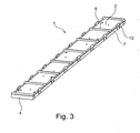
- FIG. 3 the rear view of an embodiment of a luminaire module 1 according to the invention with a circuit board 2 and an optical element 3 is shown.
- FIG. 3 It can be seen that the back of the board 2 are accessible through the surface openings between the adjacent transverse webs 8 from the back. Accordingly becomes out FIG. 3 clearly that through the interaction of latching hooks 10 and retaining elements 5 and fixing elements 6, the board 2 can be pressed against a luminaire housing with their surfaces which are arranged in the surface openings of the intermediate space, when the transverse webs 8 received in receiving recesses 12 of the lamp housing become.
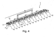
- FIG. 4 the use of a luminaire module 1 according to the invention with optical element 3 according to the invention and circuit board 2 according to the invention is shown in a luminaire housing according to the invention.
- the luminaire housing has receiving recesses 12 and locking recesses 13.
- a robot arm 14 is shown with suction cups. About the suction cups of the robot arm 14 engages the lamp module 1, in which board 2 and optical element 3 are located, and locks the lamp module 1 with the lamp housing.
- the latching hooks 10 engage in the latching recesses 13, while at the same time the transverse webs 8 are received by the receiving recesses 12 and sink into these receiving recesses 12.
- holding elements 5 and fixing elements 6 already exert a contact pressure on the optical element 3 and the printed circuit board 2 on the transverse webs 8 in the assembled idle state.
- the invention enables a modular assembly and a modular construction of luminaires.
- a luminaire module 1 can be combined with different boards 2 and different optical elements 3, wherein a particularly favorable structure can be achieved by the special design of the components according to the invention, since the board 2 can be pressed directly to the luminaire housing, so no high demands on the Stability of the lamp module 1 must be made to accommodate board 2 and 3 optical element.
- the modular construction according to the invention is particularly suitable for automatic industrial series production, wherein in pre-punched receiving recesses and Verrastaussparitch 12, 13, the fully populated lamp module 1 can be inserted and locked with the lamp housing.
Description
Die Erfindung betrifft ein Leuchtenmodul zum Halten von zumindest einem Leuchtenelement für die Montage und Fixierung des Leuchtenelements in einer Leuchte.The invention relates to a luminaire module for holding at least one luminaire element for mounting and fixing the luminaire element in a luminaire.
Ein gattungsgemäße Leuchtenmodul ist aus der
Herkömmliche Leuchten werden in mehreren Arbeitsschritten zusammengebaut. Solche herkömmlichen Leuchten umfassen ein Leuchtengehäuse, in dem Leuchtenelemente, wie beispielsweise Leuchtmittel oder Optikelemente, montiert und fixiert werden. Üblicherweise erfolgt dies durch Verschrauben der Leuchtenelemente mit dem Leuchtengehäuse. Beispielsweise werden häufig Platinen mit LEDs als Leuchtmittel verwendet, wobei durch in der Platine vorgesehene Löcher Schrauben mit einem Gewinde an dem Leuchtengehäuse verschraubt werden zur Fixierung der Platine. Ebenso werden häufig Optikelemente zur Erzeugung einer bestimmten Abstrahlcharakteristik der Leuchte so in dem Leuchtengehäuse durch Schrauben oder Klemmvorrichtungen montiert, dass die in dem Leuchtengehäuse vorgesehenen Leuchtmittel durch das Optikelement Licht abstrahlen können, so dass durch die relative Anordnung von Optikelement und Leuchtmittel die gewünschte Abstrahlcharakteristik der Leuchte gewährleistet ist.Conventional luminaires are assembled in several steps. Such conventional luminaires comprise a luminaire housing, in which luminaire elements, such as lamps or optical elements, are mounted and fixed. This is usually done by screwing the lamp elements with the lamp housing. For example, boards with LEDs are often used as lighting means, being screwed by holes provided in the board screws with a thread on the lamp housing for fixing the board. Likewise, optical elements for generating a certain radiation characteristics of the lamp are often mounted in the luminaire housing by screws or clamps that the lamps provided in the lamp housing can emit light through the optical element, so that the desired radiation characteristic of the lamp by the relative arrangement of optical element and light source is guaranteed.
Es hat sich herausgestellt, dass der herkömmliche Zusammenbau von Leuchten mittels Verschrauben von Leuchtenelementen in dem Leuchtengehäuse der Leuchte kostenintensiv ist, was zum einen durch die Materialkosten der Schrauben und zum anderen durch den hohen Zeitaufwand, den das Verschrauben mit sich bringt, bedingt ist. Darüber hinaus gestaltet sich die Wartung einer solchen Leuchte, insbesondere der Austausch von Leuchtmitteln in der Leuchte, als schwierig, da hierzu sämtliche Schraubverbindungen gelöst werden müssen und das neue Leuchtmittel aufwendig in die richtige Position in der Leuchte gebracht werden muss, bevor dann das erneute Verschrauben erfolgen kann.It has been found that the conventional assembly of luminaires by screwing lamp elements in the luminaire housing of the luminaire is cost-intensive, on the one hand by the material costs the screws and on the other by the high amount of time that the screwing brings with it. In addition, the maintenance of such a lamp, in particular the replacement of bulbs in the lamp, as difficult, since this all screw must be solved and the new bulbs consuming in the correct position in the lamp must be brought before then re-screwing can be done.
Vor diesem Hintergrund gibt es Bestrebungen, Leuchten modular aufzubauen, um damit zum einen die Herstellungskosten der Leuchte zu verringern und zum anderen die Wartung der Leuchte zu erleichtern. Ein erster Ansatz für einen solchen modularen Aufbau besteht darin, in sich geschlossene Module vorzusehen, bei denen Leuchtenelemente auf einer Trägereinheit montiert sind, wobei diese fertigen Module in großflächige Aussparungen in dem Leuchtengehäuse eingesetzt und mit dem Leuchtengehäuse verschraubt werden können. Daraus ergeben sich die Vorteile, dass die Wartung der Leuchte erleichtert ist und dass die Module getrennt von der Leuchte hergestellt werden können, wodurch der Zusammenbau der Leuchte einfacher und günstiger wird. Allerdings ist bei diesem Ansatz weiterhin ein aufwendiger Zusammenbau des Moduls erforderlich, in dem die Leuchtenelemente mit der Trägereinheit aufwendig, beispielsweise durch Verschrauben, fixiert werden müssen, und darüber hinaus muss das in die Aussparung eingesetzte Modul in sich selbst tragend sein, damit bei dem Einsetzen des Moduls in die großflächige Aussparung des Leuchtengehäuses eine ausreichende Stabilität sichergestellt ist, und weiterhin müssen an dem Modul selbst insbesondere dann, wenn Platinen mit LEDs als Leuchtmittel verwendet werden, Kühlelemente vorgesehen sein. Der entsprechend kostenintensive Aufbau eines solchen Moduls bedingt es, dass die Kostenersparnis bei der Herstellung einer Leuchte bei dem genannten Ansatz eines modularen Aufbaus gering ist.Against this background, there are efforts to build modular luminaires, so on the one hand to reduce the cost of the lamp and on the other to facilitate the maintenance of the lamp. A first approach for such a modular design is to provide self-contained modules in which lamp elements are mounted on a support unit, these finished modules can be used in large recesses in the lamp housing and bolted to the lamp housing. This has the advantages of facilitating the maintenance of the luminaire and of making the modules separate from the luminaire, making the assembly of the luminaire simpler and less expensive. However, in this approach, a complex assembly of the module is still required in which the lamp elements with the support unit consuming, for example by screwing, must be fixed, and moreover, the module inserted into the recess must be self-supporting, so when inserting the module in the large-area recess of the lamp housing sufficient stability is ensured, and further must be provided on the module itself, especially when boards are used with LEDs as lighting means cooling elements. The corresponding cost-intensive construction of such a module requires that the cost savings in the manufacture of a lamp in the mentioned approach of a modular structure is low.
Der Erfindung liegt somit die Aufgabe zugrunde, ein Leuchtenmodul zum Halten von zumindest einem Leuchtenelement für die Montage und Fixierung des Leuchtenelements in einer Leuchte bereitzustellen, das die obengenannten Nachteile bekannter Module zumindest teilweise überwindet und zu einem einfachen, kostengünstigen und wartungsfreundlichen Aufbau einer Leuchte beitragen kann.The invention is therefore an object of the invention to provide a lamp module for holding at least one lamp element for mounting and fixing the lamp element in a luminaire, which at least partially overcomes the above-mentioned disadvantages of known modules and can contribute to a simple, inexpensive and easy to maintain construction of a lamp ,
Gemäß der Erfindung wird die genannte Aufgabe durch die Bereitstellung eines Leuchtenmoduls gelöst, das zwei in Längsrichtung nebeneinander, insbesondere parallel zueinander verlaufende Seitenwände umfasst, die durch in Querrichtung verlaufende Querstege miteinander verbunden sind, wobei die Seitenwände sich vertikal zu der von der Längsrichtung und der Querrichtung definierten Ebene erstrecken. Die Seitenwände müssen dabei in Längsrichtung des Leuchtenmoduls nicht zwingend kontinuierlich verlaufen. Beispielsweise können die Seitenwände auch durch in Längsrichtung nebeneinander angeordnete und voneinander beabstandete Seitenwandelemente dargestellt sein, die in Längsrichtung miteinander verbunden sind, wobei die Seitenwandelemente beispielsweise quaderförmig oder zylinderförmig ausgebildet sein können. Vorzugsweise sind solche Seitenwandelemente eine Gerade bildend linear nebeneinander angeordnet, so dass die durch die Seitenwandelemente gebildete Seitenwand in Längsrichtung gerade verläuft. Die Seitenwandelemente können jedoch auch so nebeneinander angeordnet sein, dass sich ein in Längsrichtung geschwungener Verlauf der durch die Seitenwandelemente gebildeten Seitenwand ergibt. Entsprechend kann auch eine kontinuierlich ausgebildete Seitenwand in Längsrichtung gerade oder geschwungen verlaufen. Ein gerader Verlauf der Seitenwand kann den Vorteil mit sich bringen, dass ein Leuchtenelement besonders einfach zwischen die Seitenwände einschiebbar ist. Ein geschwungener Verlauf einer Seitenwand kann den Vorteil mit sich bringen, dass ein zwischen die Seitenwände eingeschobenes Leuchtenelement besonders gut geführt ist. Insbesondere muss der Verlauf der beiden Seitenwände in einem Ausführungsbeispiel nicht zwingend identisch sein. In einem Ausführungsbeispiel ist der Verlauf der Seitenwände in Längsrichtung identisch.According to the invention, the stated object is achieved by providing a luminaire module which comprises two longitudinal side by side, in particular parallel side walls, which are interconnected by transversely extending transverse webs, wherein the side walls are vertical to that of the longitudinal direction and the transverse direction extend defined level. The side walls do not necessarily have to run continuously in the longitudinal direction of the luminaire module. For example, the side walls can also be represented by side wall elements arranged side by side in the longitudinal direction and spaced from one another, which are connected to one another in the longitudinal direction, wherein the side wall elements can be cuboid or cylindrical, for example. Preferably, such side wall elements are arranged linearly next to one another in a straight line, so that the side wall formed by the side wall elements runs straight in the longitudinal direction. However, the side wall elements can also be arranged next to one another in such a way that a longitudinally curved profile of the side wall formed by the side wall elements results. Accordingly, a continuously formed side wall in the longitudinal direction can run straight or curved. A straight course of the side wall can bring the advantage that a lamp element is particularly easy to insert between the side walls. A curved course of a side wall can have the advantage bring themselves that a inserted between the side walls lamp element is particularly well managed. In particular, the course of the two side walls in one exemplary embodiment does not necessarily have to be identical. In one embodiment, the course of the side walls in the longitudinal direction is identical.
An zumindest einer der Seitenwände ist zumindest ein seitlicher Steg angeordnet, der in Querrichtung verläuft und von den Querstegen vertikal, d. h. vertikal zu der von der Längsrichtung und der Querrichtung definierten Ebene, beabstandet ist. Wie die Seitenwände muss auch der seitliche Steg nicht zwingend über die Längserstreckung des Leuchtenmoduls hinweg kontinuierlich verlaufen. Beispielsweise kann der Steg in Längsrichtung voneinander beabstandet angeordnete Stegelemente umfassen. Dabei sind die Querstege, die Seitenwände und der zumindest eine seitliche Steg bzw. die seitlichen Stege so zueinander angeordnet, dass sie einen Zwischenraum zumindest abschnittsweise umfassen, in den das Leuchtenelement in Längsrichtung einschiebbar ist, wobei der Zwischenraum flächige Öffnungen aufweist, die zwischen den Querstegen angeordnet sind. Der zumindest eine seitliche Steg weist ein Halteelement zum Halten des Leuchtenelements auf, das in Richtung zu den Querstegen hin federnd und zum Erzeugen eines Anpressdrucks auf das Leuchtenelement zu den Querstegen hin ausgebildet ist, wobei ein Fixierelement, insbesondere an dem zumindest einen seitlichen Steg, vertikal von den Querstegen beabstandet vorgesehen ist zum Halten des Leuchtenelements, wobei das Fixierelement in Richtung zu den Querstegen hin federnd ausgebildet ist, wobei das Fixierelement weiter von der Seitenwand entfernt ist, an der der seitliche Steg angeordnet ist, als das Halteelement.On at least one of the side walls, at least one lateral web is arranged, which extends in the transverse direction and vertically from the transverse webs, d. H. vertical to the plane defined by the longitudinal direction and the transverse direction. Like the side walls, the lateral web does not necessarily have to run continuously over the longitudinal extent of the luminaire module. For example, the web may comprise longitudinally spaced-apart web elements. In this case, the transverse webs, the side walls and the at least one lateral web or the lateral webs are arranged to each other so that they comprise a gap at least in sections, in which the lamp element is inserted in the longitudinal direction, wherein the gap has planar openings between the transverse webs are arranged. The at least one lateral web has a holding element for holding the lamp element, which is resilient in the direction of the transverse webs and for generating a contact pressure on the lamp element to the transverse webs, wherein a fixing element, in particular on the at least one lateral web, vertically spaced from the transverse webs is provided for holding the lamp element, wherein the fixing element is resilient in the direction of the transverse webs, wherein the fixing element is further removed from the side wall on which the lateral web is arranged, as the holding element.
Durch das Halteelement kann somit auf ein Leuchtenelement, das in den Zwischenraum eingeschoben ist, ein Anpressdruck zu den Querstegen hin erzeugt werden. Dadurch ist das erfindungsgemäße Leuchtenmodul so ausgebildet, dass ein in dem Zwischenraum zu haltendes Leuchtenelement möglicherweise über Druckkontakt zwischen Halteelement und Querstegen in dem Leuchtenmodul gehalten sein kann. Beispielsweise können in einer Ausführungsform zwei oder mehr in dem Zwischenraum zu haltende Leuchtenelemente vertikal übereinander in dem Zwischenraum angeordnet werden, wobei das Halteelement einen Anpressdruck auf das ihm am nächsten liegende Leuchtenelement ausüben kann, wobei der Anpressdruck von diesem Leuchtenelement zumindest teilweise an zumindest eines der weiteren Leuchtenelemente zum Halten des zumindest einen weiteren Leuchtenelements weitergegeben werden kann. Ferner kann das Halteelement auf das in dem Zwischenraum zu haltende Leuchtenelement bzw. die in dem Zwischenraum angeordneten Leuchtenelemente einen Anpressdruck gegen eine von außen durch die flächigen Öffnungen vertikal auf das Leuchtenmodul ausgeübte Kraft ausüben, wodurch das Leuchtenmodul gegen eine diese Kraft erzeugende Vorrichtung gepresst werden kann.By the retaining element can thus on a lamp element which is inserted into the intermediate space, a contact pressure generated to the transverse webs. As a result, the luminaire module according to the invention is designed so that a lamp element to be held in the intermediate space may possibly be held in pressure contact between the holding element and transverse webs in the luminaire module. For example, in one embodiment, two or more to be held in the gap luminaire elements are vertically stacked in the space, the holding element can exert a contact pressure on him nearest lamp element, the contact pressure of this lamp element at least partially to at least one of the other Luminaire elements for holding the at least one further luminaire element can be passed. Furthermore, the holding element can exert on the space to be held in the space lamp element or arranged in the space lamp elements a contact pressure against a force exerted externally by the surface openings vertically on the lamp module force, whereby the lamp module can be pressed against a force generating device this device ,
Dabei kann das Halteelement verschiedenartig ausgestaltet sein. Beispielsweise kann das Halteelement in Längsrichtung kontinuierlich ausgebildet sein oder aber auch in Längsrichtung voneinander beabstandete Halteelementabschnitte umfassen. Beispielsweise kann das Halteelement als zusätzliches Bauteil an dem seitlichen Steg angeordnet sein. Beispielsweise kann das Halteelement einstückig mit dem seitlichen Steg ausgebildet sein. Beispielsweise kann das Halteelement durch die Form des seitlichen Stegs selbst realisiert sein. Das Halteelement kann beispielsweise durch die zu den Querstegen hinweisende Seite des seitlichen Stegs realisiert sein. Beispielsweise kann der seitliche Steg eine entsprechende Profilierung aufweisen, die das Halteelement darstellt. Beispielsweise kann das Halteelement mehrere, insbesondere in Längsrichtung voneinander beabstandete, in dem Steg integrierte Biegefedern umfassen. Die Biegefedern können somit die Halteelementabschnitte darstellen. Beispielsweise können solche Biegefedern einstückig mit dem Steg ausgebildet sein, beispielsweise durch in den Steg integrierte, hakenartige Vorsprünge, die zu dem Steg elastisch sind.In this case, the holding element can be designed differently. For example, the holding element can be formed continuously in the longitudinal direction or else also comprise holding element sections which are spaced apart from one another in the longitudinal direction. For example, the holding element can be arranged as an additional component on the lateral web. For example, the retaining element may be formed integrally with the lateral web. For example, the holding element can be realized by the shape of the lateral web itself. The holding element can be realized for example by the side facing the transverse webs side of the web page. For example, the lateral web may have a corresponding profiling, which represents the holding element. For example, the holding element several, in particular in the longitudinal direction comprise spaced apart, integrated in the web bending springs. The bending springs can thus represent the holding element sections. For example, such bending springs may be integrally formed with the web, for example by integrated into the web, hook-like projections which are elastic to the web.
Der Zwischenraum ist von den Querstegen, den Seitenwänden und dem zumindest einen seitlichen Steg nicht geschlossen umfasst. Vielmehr weist der Zwischenraum flächige Öffnungen auf, die zwischen den Querstegen angeordnet sind. Insbesondere können in einer Ausführungsform die flächigen Öffnungen durch die Querstege und die Seitenwände definiert sein, so dass die flächigen Öffnungen zwischen zwei benachbarten Querstegen und den Seitenwänden flächig geschlossen verlaufen. Vorzugsweise sind die flächigen Öffnungen so groß ausgebildet, dass die durch die sämtlichen flächigen Öffnungen des Leuchtenmoduls gemeinsam eingenommene Fläche einen wesentlichen Anteil des Querschnitts des Leuchtenmoduls in der durch die Längsrichtung und die Querrichtung definierten Ebene ausmachen, insbesondere einen Anteil von mehr als 50 % dieses Querschnitts, insbesondere einen Anteil von mehr als 70 %, insbesondere einen Anteil von mehr als 90 % dieses Querschnitts.The intermediate space is not enclosed by the transverse webs, the side walls and the at least one lateral web. Rather, the gap on planar openings, which are arranged between the transverse webs. In particular, in one embodiment, the planar openings may be defined by the transverse webs and the side walls, so that the planar openings between two adjacent transverse webs and the side walls are closed in a flat manner. Preferably, the areal openings are formed so large that the surface occupied jointly by the entire areal openings of the luminaire module make up a substantial portion of the cross section of the luminaire module in the plane defined by the longitudinal direction and the transverse direction, in particular a proportion of more than 50% of this cross section , in particular a proportion of more than 70%, in particular a proportion of more than 90% of this cross section.
Das erfindungsgemäße Leuchtenmodul weist den Vorteil auf, dass Leuchtenelemente besonders einfach in das Leuchtenmodul eingeführt und in dem Leuchtenmodul gehalten werden können. So können in einem Ausführungsbeispiel zugeordnete Leuchtenelemente, ohne dass zusätzliche Fixierungsmaßnahmen erforderlich sind, seitlich in den Zwischenraum des Leuchtenmoduls eingeschoben werden, wobei durch das Zusammenwirken von Querstegen und Halteelement eine ausreichende Haltekraft zum Halten des Leuchtenelements in dem Leuchtenmodul gewährleistet ist. Die Querstege verleihen dem erfindungsgemäßen Leuchtenmodul eine ausreichende Stabilität.The luminaire module according to the invention has the advantage that luminaire elements can be introduced into the luminaire module in a particularly simple manner and held in the luminaire module. Thus, in one embodiment, associated lighting elements, without additional fixation measures are required to be inserted laterally into the gap of the lamp module, wherein a sufficient holding force for holding the lamp element is ensured in the lamp module by the interaction of transverse webs and retaining element. The transverse webs give the lamp module according to the invention a sufficient Stability.
Durch die großflächigen Öffnungen zwischen den Querstegen ist gewährleistet, dass ein Leuchtenmodul, in dem ein Leuchtenelement angeordnet ist, so in ein korrespondierendes Leuchtengehäuse angeordnet werden kann, dass das Leuchtenelement, das durch das Halteelement eine Anpresskraft zu den Querstegen hin erfahren kann, über in den flächigen Öffnungen angeordnete Kontaktstellen des Leuchtengehäuses flächig an dem Leuchtengehäuse anliegen und gehalten sein kann. Bei mehreren vertikal übereinander angeordneten Leuchtenelementen gilt dies bezogen auf die Gesamtheit der Leuchtenelemente entsprechend. Dadurch ist für eine zuverlässige und haltbare Montage eines Leuchtenelements mittels des Leuchtenmoduls in einem Leuchtengehäuse keine besonders hohe Stabilität des Leuchtenmoduls erforderlich, da bei einer Fixierung des Leuchtenmoduls mit einem in dem Leuchtenmodul angeordneten Leuchtenelement das Leuchtenelement über die flächigen Öffnungen in direkten Kontakt mit dem Leuchtengehäuse gebracht werden kann. Darüber hinaus kann beispielsweise dann, wenn das Leuchtenelement als Platine mit LEDs ausgebildet ist, ein Kühlkontakt zwischen Leuchtengehäuse und Leuchtenelement über die flächigen Öffnungen gewährleistet sein. Hierzu kann insbesondere das Vorsehen von entsprechend großen flächigen Öffnungen vorteilhaft sein.Due to the large-area openings between the transverse webs ensures that a lamp module in which a lamp element is arranged, can be arranged in a corresponding lamp housing, that the lamp element, which can experience a contact force to the transverse webs through the holding element, in the planar openings arranged contact points of the lamp housing abut flat against the lamp housing and can be kept. In the case of several luminaire elements arranged vertically one above the other, this applies correspondingly to the totality of the luminaire elements. As a result, a particularly high stability of the lamp module is required for a reliable and durable installation of a lamp element by means of the lamp module in a lamp housing, as brought in a fixation of the lamp module with a lamp module arranged in the lamp element, the lamp element on the flat openings in direct contact with the lamp housing can be. In addition, for example, when the lamp element is designed as a board with LEDs, a cooling contact between the lamp housing and lamp element can be ensured on the surface openings. For this purpose, in particular the provision of correspondingly large area openings may be advantageous.
Das erfindungsgemäße Leuchtenmodul umfasst ferner, insbesondere an dem seitlichen Steg, ein Fixierelement zum Halten eines Leuchtenelements, wobei das Fixierelement vertikal von den Querstegen beabstandet ist und in Richtung zu den Querstegen hin federnd ausgebildet ist. Das Fixierelement kann beispielsweise an einem weiteren seitlichen Steg oder direkt an der Seitenwand angeordnet sein. Wie das Halteelement ermöglicht auch das Fixierelement somit ein zuverlässiges Halten des Leuchtenelements in dem Zwischenraum, indem es einen Anpressdruck auf das Leuchtenelement zu den Querstegen hin erzeugen kann. In einer Ausführungsform kann das Leuchtenelement zwischen Fixierelement und Querstegen gehalten sein. Das Fixierelement kann in Längsrichtung kontinuierlich oder auch unterbrochen ausgebildet sein. Beispielsweise kann ein Leuchtenelement gleichzeitig durch Fixierelement und Halteelement in dem Leuchtenmodul gehalten sein. In einer Ausführungsform hält das Halteelement ein erstes Leuchtenelement und das Fixierelement ein zweites Leuchtenelement. In einer weiteren Ausführungsform können zwei Leuchtenelemente in dem Leuchtenmodul vorgesehen sein, die übereinander angeordnet sind, wobei das Halteelement einen Anpressdruck auf das erste Leuchtenelement ausüben kann zum Halten des ersten Leuchtenelements, und wobei das Fixierelement einen Anpressdruck auf das zweite Leuchtenelement ausüben kann, wodurch das zweite Leuchtenelement auf das erste Leuchtenelement und auf die Querstege oder beispielsweise auf eine durch die flächigen Öffnungen in den Zwischenraum ragende Vorrichtung, an der das Leuchtenmodul befestigt ist, gepresst sein kann.The luminaire module according to the invention further comprises, in particular on the lateral web, a fixing element for holding a lamp element, wherein the fixing element is vertically spaced from the transverse webs and is resilient in the direction of the transverse webs. The fixing element may be arranged, for example, on a further lateral web or directly on the side wall. Like the retaining element also allows the fixing thus a reliable holding of the lamp element in the Interspace, by being able to generate a contact pressure on the lamp element to the transverse webs out. In one embodiment, the lighting element between fixing and transverse bars can be maintained. The fixing can be formed continuously or interrupted in the longitudinal direction. For example, a luminaire element can be held in the luminaire module at the same time by fixing element and retaining element. In one embodiment, the holding element holds a first luminaire element and the fixing element holds a second luminaire element. In a further embodiment, two lamp elements may be provided in the lamp module, which are arranged one above the other, wherein the holding element can exert a contact pressure on the first lamp element for holding the first lamp element, and wherein the fixing element can exert a contact pressure on the second lamp element, whereby the second lamp element on the first lamp element and on the transverse webs or, for example, on a protruding through the planar openings in the intermediate device to which the lamp module is attached, may be pressed.
Das Fixierelement ist weiter von der Seitenwand entfernt, an der der seitliche Steg angeordnet ist, als das Halteelement. Damit kann beispielsweise ein Halten eines Leuchtenelements in dem Leuchtenmodul gewährleistet sein, bei dem das Halteelement nahe an der Seitenwand einen Anpressdruck auf das Leuchtenelement ausübt und das Fixierelement nahe der Quermitte des Leuchtenmoduls einen Anpressdruck auf das Leuchtenelement ausübt, so dass das Leuchtenelement gleichmäßig durch Halteelement und Fixierelement einen Anpressdruck, beispielsweise auf die Querstege erfährt. Auch kann beispielsweise bei einer entsprechenden Anordnung ein erstes Leuchtenelement durch das näher an der Seitenwand gelegene Halteelement zu den Querstegen gepresst werden, während ein zweites Leuchtenelement durch das Fixierelement näher an der Quermitte des Leuchtenmoduls zu den Querstegen gepresst wird. Die entsprechende Anordnung kann auch dann vorteilhaft sein, wenn das Fixierelement einen Anpressdruck auf ein zweites Leuchtenelement und darüber auch auf ein erstes Leuchtenelement ausübt, wobei das Leuchtenelement zusätzlich durch das Halteelement gehalten wird, so dass ein gleichmäßiger Anpressdruck zu den Querstegen gewährleistet ist.The fixing element is further removed from the side wall, on which the lateral web is arranged, as the holding element. This can be ensured, for example, holding a lamp element in the lamp module, in which the holding element exerts a contact pressure on the lamp element close to the side wall and the fixing near the transverse center of the lamp module exerts a contact pressure on the lamp element, so that the lamp element evenly by holding element and Fixing a contact pressure, for example, learns on the transverse webs. Also, for example, in a corresponding arrangement, a first lamp element can be pressed by the closer to the side wall holding member to the transverse webs, while a second lamp element by the fixing is pressed closer to the transverse center of the lamp module to the transverse webs. The corresponding arrangement may also be advantageous if the fixing element exerts a contact pressure on a second lamp element and also on a first lamp element, wherein the lamp element is additionally held by the holding element, so that a uniform contact pressure is ensured to the transverse webs.
Das erfindungsgemäße Leuchtenmodul ermöglicht durch die Führung und das Halten eines Leuchtenelements bzw. der Leuchtenelemente somit eine zuverlässige Fixierung des Leuchtenelements bzw. der Leuchtenelemente und kann dabei wegen seines erfindungsspezifischen Aufbaus besonders kostengünstig hergestellt werden, da keine besonders hohen Anforderungen an die Stabilität des Leuchtenmoduls gestellt werden müssen. Das erfindungsgemäße Leuchtenmodul kann zum Halten von zumindest einem standardisierten Leuchtenelement ausgebildet sein. Durch das Vorsehen von standardisierten Leuchtenelementen kann die Herstellung von Leuchten noch weiter vereinfacht und vergünstigt sein. Beispielsweise können für standardisierte Leuchtenelemente Standardmaße vorgesehen sein, die auf die Abmessungen des erfindungsgemäßen Leuchtenmoduls abgestimmt sind, so dass ein standardisiertes Leuchtenelement in dem Leuchtenmodul gehalten werden kann. Beispielsweise können aus einem Pool an standardisierten Leuchtenelementen bestimmte Leuchtenelemente für die Realisierung einer bestimmten Leuchte mit bestimmten Eigenschaften ausgewählt werden. Das erfindungsgemäße Leuchtenmodul ermöglicht somit zum einen die kostengünstige Herstellung von Leuchten und zum anderen den einfachen Austausch von Leuchtenelementen zur Wartung der Leuchte.The luminaire module according to the invention thus enables a reliable fixation of the luminaire element or the luminaire elements by the guidance and holding of a luminaire element or the luminaire elements and can be produced particularly cost-effectively because of its fiction-specific structure, since no particularly high demands are placed on the stability of the luminaire module have to. The luminaire module according to the invention can be designed to hold at least one standardized luminaire element. By providing standardized luminaire elements, the production of luminaires can be further simplified and discounted. For example, standard dimensions can be provided for standardized luminaire elements, which are matched to the dimensions of the luminaire module according to the invention, so that a standardized luminaire element can be held in the luminaire module. For example, from a pool of standardized luminaire elements, certain luminaire elements can be selected for the realization of a specific luminaire with particular properties. The luminaire module according to the invention thus enables on the one hand the cost-effective production of luminaires and, on the other hand, the simple replacement of luminaire elements for the maintenance of the luminaire.
In einer vorteilhaften Ausführungsform ist das Leuchtenmodul einstückig, insbesondere als Spritzgussteil, ausgebildet. Dadurch kann das Leuchtenmodul besonders kostengünstig hergestellt werden. Darüber hinaus ist kein Zusammenbau des Leuchtenmoduls erforderlich. Durch seine Ausgestaltung als Kunststoff-, insbesondere als Spritzgussteil ist eine ausreichende Flexibilität und Stabilität des Leuchtenmoduls gewährleistet. In einer Ausführungsform sind die Querstege und die Seitenwände gemeinsam einstückig ausgebildet, in einer weiteren Ausführungsform die Querstege, die Seitenwände, die seitlichen Stege und die Halteelemente, in einer weiteren Ausführungsform auch die Fixierelemente. Die einstückigen Bauteile können jeweils ein Spritzgussteil sein.In an advantageous embodiment, the luminaire module is integrally formed, in particular as an injection molded part. As a result, the luminaire module is particularly cost-effective getting produced. In addition, no assembly of the lamp module is required. Due to its design as a plastic, in particular as an injection molded part sufficient flexibility and stability of the lamp module is guaranteed. In one embodiment, the transverse webs and the side walls are formed integrally together, in a further embodiment, the transverse webs, the side walls, the lateral webs and the holding elements, in a further embodiment, the fixing elements. The one-piece components may each be an injection molded part.
In einer vorteilhaften Ausführungsform weist jede der Seitenwände einen seitlichen Steg auf. Die beiden seitlichen Stege können in einer Ausführungsform identisch ausgebildet sein und jeweils ein identisches Halteelement und möglicherweise darüber hinaus ein identisches Fixierelement umfassen. Die seitlichen Stege, die jeweils an einer Seitenwand angeordnet sind, können jedoch auch unterschiedlich ausgebildet ein, beispielsweise kann ein seitlicher Steg nur ein Halteelement und der andere seitliche Steg Halte- und Fixierelement aufweisen. Gerade durch eine vorteilhafte Ausführungsform umfassend zwei seitliche Stege, von denen jeder an einer Seitenwand angeordnet ist, kann ein besonders gleichmäßiger Anpressdruck auf ein oder mehrere Leuchtenelemente gewährleistet sein.In an advantageous embodiment, each of the side walls has a lateral web. The two lateral webs can be formed identically in one embodiment and each comprise an identical holding element and possibly also an identical fixing element. However, the lateral webs, which are each arranged on a side wall, can also have a different design, for example, a lateral web can have only one retaining element and the other lateral web holding and fixing element. Just by an advantageous embodiment comprising two lateral webs, each of which is arranged on a side wall, a particularly uniform contact pressure on one or more lighting elements can be ensured.
Vorzugsweise ist das Fixierelement als Profil in dem seitlichen Steg ausgebildet. Damit kann das Fixierelement in dem seitlichen Steg direkt integriert sein bzw. der seitliche Steg direkt als Fixierelement wirken. Dadurch ist eine besonders günstige Herstellung des Leuchtenmoduls möglich. Insbesondere kann das Fixierelement an dem der Seitenwand gegenüberliegenden Ende des seitlichen Stegs angeordnet sein. Dadurch kann sich zwischen einem zu haltenden Leuchtenelement und dem Fixierelement eine Schnittstelle ausbilden, über die das Fixierelement auf das Leuchtenelement drückt, die insbesondere ein leichtes Einschieben des Leuchtenelements in das Leuchtenmodul fördert.Preferably, the fixing element is designed as a profile in the lateral web. Thus, the fixing element can be integrated directly in the lateral web or the lateral web directly act as a fixing. As a result, a particularly favorable production of the lamp module is possible. In particular, the fixing element may be arranged on the side wall opposite the end of the lateral web. This can be between a lamp element to be held and the fixing a Form interface over which presses the fixing element on the lamp element, which promotes in particular a slight insertion of the lamp element in the lamp module.
Vorzugsweise sind Fixierelement und Halteelement an dem seitlichen Steg so weit voneinander beabstandet, dass sie im Wesentlichen unabhängig voneinander eine Federkraft auf ein Leuchtenelement zu den Querstegen hin ausüben können.Preferably, fixing element and retaining element on the lateral web are so far apart from each other that they can exert a spring force on a lamp element to the transverse webs substantially independently of each other.
Vorzugsweise ist der zumindest eine seitliche Steg in voneinander getrennte Längsabschnitte unterteilt. Dadurch kann eine bessere elastische Eigenschaft des seitlichen Stegs gewährleistet sein, was insbesondere für die von dem Fixierelement und/oder dem Halteelement ausgeübte Federkraft auf ein Leuchtenelement vorteilhaft sein kann.Preferably, the at least one lateral web is subdivided into separate longitudinal sections. As a result, a better elastic property of the lateral web can be ensured, which can be advantageous in particular for the spring force exerted by the fixing element and / or the retaining element on a lamp element.
In einer Ausführungsform sind Rastnasen an der von dem Zwischenraum wegweisenden Seite der Seitenwände angeordnet zum Verrasten einer Leuchtenabdeckung an dem Leuchtenmodul. Beispielsweise können die Rastnasen als Aussparungen ausgebildet sein, in die an der Leuchtenabdeckung angeordnete Vorsprünge einrasten können. Beispielsweise können die Rastnasen als Vorsprünge ausgebildet sein, die in an der Leuchtenabdeckung angeordnete Aussparungen einrasten können. Vorsprünge und Aussparungen korrespondieren jeweils. Mit einem solchen erfindungsgemäßen Leuchtenmodul lässt sich eine Leuchte besonders einfach und kostengünstig herstellen, indem der Leuchtenkörper im Wesentlichen ausschließlich durch die Leuchtenabdeckung und das Leuchtenmodul gegeben ist.In one embodiment, latching lugs are arranged on the side facing away from the gap side of the side walls for latching a lamp cover to the lamp module. For example, the detents may be formed as recesses into which projections arranged on the lamp cover can engage. For example, the locking lugs may be formed as projections which can engage in arranged on the lamp cover recesses. Projections and recesses correspond respectively. With such a luminaire module according to the invention, a luminaire can be produced in a particularly simple and cost-effective manner, in that the luminaire body is given essentially exclusively by the luminaire cover and the luminaire module.
In einer Ausführungsform sind die Querstege in einem konstanten Abstand parallel zueinander angeordnet und/oder weisen jeweils dieselben geometrischen Abmessungen auf. Die geometrischen Abmessungen beziehen sich dabei auf die Höhe, Länge, Breite und/oder Form der Querstege. Durch die Anordnung der Querstege in einem konstanten Abstand und/oder die identische Ausgestaltung der Querstege eignet sich das Leuchtenmodul besonders für die Serienfertigung von Leuchten. Denn damit können erfindungsgemäße Leuchtenmodule in korrespondierende Leuchtengehäuse an beliebigen solchen Stellen eingebaut werden, an denen die Leuchtengehäuse den Querstegen zugeordneter Aussparungen aufweisen, wobei die Leuchtengehäuse vorab an die Querstege bzw. die Anordnung der Querstege der zugeordneten Leuchtenmodule angepasst werden können.In one embodiment, the transverse webs are arranged at a constant distance parallel to each other and / or each have the same geometric dimensions. The geometric dimensions relate to the height, length, width and / or shape of the transverse webs. By the Arrangement of the transverse webs at a constant distance and / or the identical configuration of the transverse webs, the lamp module is particularly suitable for the mass production of lights. Because so that luminaire modules according to the invention can be installed in corresponding luminaire housing at any such points where the luminaire housing has the transverse webs associated recesses, the luminaire housing can be adapted in advance to the transverse webs or the arrangement of the transverse webs of the associated lighting modules.
Vorzugsweise ist an zumindest einer der Seitenwände und/oder an zumindest einem der Querstege und/oder zumindest einem der seitlichen Stege ein Sperrelement zum Sperren der Längsbeweglichkeit zumindest eines der in dem Leuchtenmodul gehaltenen Leuchtenelemente vorgesehen. Ein solches Sperrelement kann beispielsweise als Vorsprung ausgebildet sein, der einen Anschlag für das Leuchtenelement beim Einschieben des Leuchtenelements in das Leuchtenmodul bildet. Auch kann ein solches Sperrelement beispielsweise als Vorsprung ausgebildet sein, der in eine Aussparung oder Vertiefung eines korrespondierenden, einzuschiebenden Leuchtenelements greifen kann.Preferably, a blocking element is provided on at least one of the side walls and / or on at least one of the transverse webs and / or at least one of the lateral webs for blocking the longitudinal mobility of at least one of the lamp elements held in the lamp module. Such a blocking element may for example be formed as a projection which forms a stop for the lamp element when inserting the lamp element into the lamp module. Also, such a blocking element may for example be formed as a projection which can engage in a recess or recess of a corresponding, to be inserted luminous element.
In einer Ausführungsform ist an zumindest einem der Längsenden des Leuchtenmoduls ein Kopfstück vorgesehen, das den Zwischenraum als Begrenzungswand begrenzt. Das Kopfstück kann somit die zugeordnete Längsseite des Leuchtenmoduls abschließen. Beispielsweise kann ein Kopfstück an einem Längsende des Leuchtenmoduls einstückig mit dem Leuchtenmodul ausgebildet sein, so dass das Kopfstück beim Einschieben eines Leuchtenelements in das Leuchtenmodul einen Anschlag für das Leuchtenelement bildet. Auch kann beispielweise ein Kopfstück eine Rastvorrichtung aufweisen, die an einem Längsende des Leuchtenmoduls in das Leuchtenmodul verrastet werden kann, beispielsweise in eine korrespondierende Rastvorrichtung, die an dem Leuchtenmodul angeordnet ist. Beispielsweise kann ein solches verrastbares Kopfstück an jedem der beiden Längsenden des Leuchtenmoduls vorgesehen sein. Durch das Vorsehen von zwei solcher Kopfstücke kann beispielsweise ein in das Leuchtenmodul eingeschobenes Leuchtenelement gegen eine Längsverschiebung in dem Leuchtenmodul zuverlässig gesichert sein. Beispielsweise können solche Kopfstücke auch einen optischen Abschluss bilden, was insbesondere dann vorteilhaft sein kann, wenn eine Leuchte auf einfache Art und Weise im Wesentlichen aus einem Leuchtenmodul und einer Leuchtenabdeckung als Leuchtenkörper besteht.In one embodiment, a head piece is provided on at least one of the longitudinal ends of the lamp module, which limits the intermediate space as a boundary wall. The head piece can thus complete the associated longitudinal side of the lamp module. For example, a head piece at one longitudinal end of the luminaire module can be formed integrally with the luminaire module, so that the head piece forms a stop for the luminaire element when a luminaire element is inserted into the luminaire module. Also, for example, a head piece having a locking device which can be latched at a longitudinal end of the lamp module in the lamp module, for example, in a corresponding locking device, which on the lamp module is arranged. For example, such a lockable head piece may be provided at each of the two longitudinal ends of the lamp module. By providing two such head pieces, for example, a lamp element inserted into the lamp module can be reliably secured against longitudinal displacement in the lamp module. For example, such head pieces can also form an optical termination, which can be advantageous in particular if a luminaire consists essentially of a luminaire module and a luminaire cover as a luminaire body in a simple manner.
Das Leuchtenmodul kann ferner eine erste Rasteinheit aufweisen zum Verrasten des Leuchtenmoduls in einem Leuchtengehäuse, wobei die Rasteinheit so ausgebildet sein kann, dass sie beim Verrasten mit einer korrespondierenden, am Leuchtengehäuse angeordneten zweiten Rasteinheit eine Kraft auf das Leuchtenmodul mit einer Komponente vertikal von dem seitlichen Steg zu den Querstegen hin erzeugt. Die erste Rasteinheit kann insbesondere Rasthaken umfassen. Durch ein solches Verrasten des Leuchtenmoduls mit dem Leuchtengehäuse wird das Leuchtenmodul gegen das Leuchtengehäuse gepresst. Dies kann insbesondere dann vorteilhaft sein, wenn in dem Leuchtengehäuse Aussparungen für die Querstege vorgesehen sind, so dass ein in das Leuchtenmodul eingeschobenes Leuchtenelement über die flächigen Öffnungen mit dem Leuchtengehäuse in Kontakt stehen kann und durch das Zusammenwirken von der durch die erste Rasteinheit, insbesondere die Rasthaken, und die zweite Rasteinheit erzeugten Kraft mit der durch das Halteelement und/oder das Fixierelement erzeugten Kraft gegen das Leuchtengehäuse gepresst wird. Dadurch kann beispielsweise eine besonders gute Fixierung eines Leuchtenelements an einem Leuchtengehäuse über das Zusammenwirken des Leuchtenmoduls mit dem Leuchtengehäuse gewährleistet sein. Insbesondere kann dadurch auch ein besonders guter Wärmekontakt zwischen dem Leuchtenelement und dem Leuchtengehäuse hergestellt sein, so dass Wärme von dem Leuchtenelement an das Leuchtengehäuse und darüber nach außen abgeführt werden kann.The luminaire module may further comprise a first latch unit for latching the luminaire module in a luminaire housing, wherein the latching unit may be configured such that when latched to a corresponding second latch unit disposed on the luminaire housing, it applies a force to the luminaire module with a component vertically from the lateral rib generated towards the transverse webs. The first latching unit may in particular comprise latching hooks. By such a locking of the lamp module with the lamp housing, the lamp module is pressed against the lamp housing. This can be advantageous in particular when recesses are provided for the transverse webs in the luminaire housing so that a luminous element inserted into the luminaire module can be in contact with the luminaire housing via the laminar openings and can be brought into contact with the luminaire housing by the interaction of the first latching unit, in particular the Snap hook, and the second latch unit generated force is pressed with the force generated by the holding member and / or the fixing member against the lamp housing. As a result, for example, a particularly good fixation of a luminaire element to a luminaire housing via the interaction of the luminaire module with the luminaire housing can be ensured. In particular, this can also be a be made particularly good thermal contact between the lamp element and the lamp housing, so that heat from the lamp element to the lamp housing and can be dissipated to the outside.
Erste Rasteinheit und zweite Rasteinheit korrespondieren miteinander. Beispielsweise kann die erste Rasteinheit Rasthaken umfassen, während die zweite Rasteinheit Aussparungen umfasst. Beispielsweise kann die erste Rasteinheit Aussparungen umfassen, während die zweite Rasteinheit Rasthaken umfasst. Insbesondere können die Rasteinheiten sowohl Aussparungen als auch Rasthaken umfassen, wobei jeweils ein Rasthaken mit einer Aussparung korrespondiert. Insbesondere können anstelle der Aussparungen jeweils Abschlusskanten vorgesehen sein, mit denen die jeweiligen Rasthaken verrasten können.First latch unit and second latch unit correspond to each other. For example, the first latching unit may comprise latching hooks, while the second latching unit comprises recesses. For example, the first latching unit may comprise recesses, while the second latching unit comprises latching hooks. In particular, the locking units may comprise both recesses and latching hooks, wherein in each case a latching hook corresponds with a recess. In particular, instead of the recesses in each case end edges may be provided with which the respective latching hooks can lock.
Der Fachmann ist mit der Ausbildung entsprechender korrespondierender Rasteinheiten, insbesondere entsprechender Rasthaken hinreichend vertraut. Beispielsweise können die Rasthaken einen Querschnitt aufweisen, der sich in Richtung von dem seitlichen Steg zu den Querstegen hin abschnittsweise verjüngt.The skilled worker is sufficiently familiar with the formation of corresponding corresponding locking units, in particular corresponding latching hooks. For example, the latching hooks may have a cross section which tapers in sections in the direction from the lateral web to the transverse webs.
Durch ein entsprechendes Verrasten kann somit ein Anpressen eines Leuchtenelements gegen ein Leuchtengehäuse gewährleistet sein, da dieses Leuchtenelement in dem Leuchtenmodul entlang der Querstege eingeschoben ist und somit auf den Querstegen aufliegen kann, wobei Halteelement und/oder Fixierelement eine Kraft auf das Leuchtenelement in Richtung zu den Querstegen hin ausüben, so dass durch ein Verrasten, bei dem eine Kraft mit einer Komponente vertikal von dem seitlichen Steg zu den Querstegen hin auf das Leuchtenmodul erzeugt wird, ein entsprechender Anpressdruck gewährleistet ist, indem das Leuchtengehäuse eine vertikale Kraft auf das Leuchtenelement durch die flächigen Öffnungen ausübt.By a corresponding latching a pressing of a lamp element can thus be ensured against a lamp housing, since this lamp element is inserted in the lamp module along the transverse webs and thus can rest on the transverse webs, wherein the holding element and / or fixing a force on the lamp element in the direction of the Exercise transverse webs, so that by a latching, in which a force is generated with a component vertically from the lateral web to the transverse webs towards the lamp module, a corresponding contact pressure is ensured by the lamp housing a vertical force on the lamp element by the flat Exerts openings.
Insbesondere können sich Rasthaken, aus denen die erste Rasteinheit ganz oder teilweise bestehen kann, an dem vertikalen Ende der Seitenwände, an denen die Querstege angeordnet sind, vertikal über die Seitenwände hinaus erstrecken. Dadurch kann ein besonders einfaches und effektives Verrasten des Leuchtenmoduls mit dem Leuchtengehäuse gewährleistet sein.In particular, latching hooks, from which the first latching unit may be wholly or partially, extend vertically beyond the side walls at the vertical end of the side walls on which the transverse webs are arranged. As a result, a particularly simple and effective latching of the luminaire module to the luminaire housing can be ensured.
In einer Ausführungsform umfasst die erste Rasteinheit externe Rastelemente. In einer weiteren Ausführungsform umfasst die zweite Rasteinheit externe Rastelemente. Beispielsweise kann die zweite Rasteinheit ferner Aussparungen aufweisen, in denen externe Rastelemente fixiert, beispielsweise verrastet werden können. Die in den Aussparungen fixierten externen Rastelemente können mit der ersten Rasteinheit verrasten, indem die externen Rastelemente zu der ersten Rasteinheit entsprechend wie oben erläutert korrespondieren. Beispielsweise können die externen Rastelemente ein Federstahlelement aufweisen. Dadurch können sich dieselben Vorteile aus dem Verrasten wie oben beschrieben im Falle der Ausführungsform mit Rasthaken an dem Leuchtenmodul oder an dem Leuchtengehäuse ergeben. Durch die externen Rastelemente kann ein besonders einfacher modularer Aufbau ermöglicht sein.In one embodiment, the first latching unit comprises external latching elements. In a further embodiment, the second latching unit comprises external latching elements. For example, the second latching unit may further comprise recesses in which external latching elements can be fixed, for example latched. The fixed in the recesses external locking elements can lock with the first locking unit by the external locking elements correspond to the first locking unit according to the above explained. For example, the external locking elements may comprise a spring steel element. As a result, the same advantages can result from the latching as described above in the case of the embodiment with latching hooks on the luminaire module or on the luminaire housing. Due to the external locking elements, a particularly simple modular construction can be made possible.
Die Erfindung betrifft ferner ein Leuchtengehäuse, das mit einem erfindungsgemäßen Leuchtenmodul zur Aufnahme des Leuchtenmoduls korrespondiert. Die Erfindung bezieht sich somit auf ein Leuchtengehäuse, das mit einem erfindungsgemäßen Leuchtenmodul in Beziehung steht, wobei das erfindungsgemäße Leuchtengehäuse und das erfindungsgemäße Leuchtenmodul sich gegenseitig ergänzen und zum miteinander Zusammenwirken ausgebildet sind. Das erfindungsgemäße Leuchtengehäuse ist so ausgebildet, dass es mit einem Leuchtenmodul korrespondiert zur Aufnahme des Leuchtenmoduls, wobei das Leuchtenmodul zum Halten von zumindest einem standardisierten Leuchtenelement für die Montage und Fixierung des Leuchtenelements in einer Leuchte ausgebildet ist, das Leuchtenmodul umfassend zwei in Längsrichtung nebeneinander, insbesondere parallel zueinander verlaufende Seitenwände, die durch in Querrichtung verlaufende Querstege miteinander verbunden sind, wobei die Seitenwände sich vertikal zu der von der Längsrichtung und der Querrichtung definierten Ebene erstrecken, wobei an zumindest einer der Seitenwände zumindest ein seitlicher Steg angeordnet ist, der in Querrichtung verläuft und von den Querstegen vertikal beabstandet ist, wobei die Querstege, die Seitenwände und der seitliche Steg so zueinander angeordnet sind, dass sie einen Zwischenraum zumindest abschnittsweise umfassen, in den das Leuchtenelement in Längsrichtung einschiebbar ist, wobei der Zwischenraum flächige Öffnungen aufweist, die zwischen den Querstegen angeordnet sind, wobei der seitliche Steg ein Halteelement zum Halten des Leuchtenelements aufweist, das in Richtung zu den Querstegen hin federnd und insbesondere zum Erzeugen eines Anpressdrucks auf das Leuchtenelement zu den Querstegen hin ausgebildet ist, wobei insbesondere ein Fixierelement, insbesondere an dem zumindest einen seitlichen Steg, vertikal von den Querstegen beabstandet vorgesehen ist zum Halten des Leuchtenelements und/oder eines weiteren Leuchtenelements, wobei insbesondere das Fixierelement in Richtung zu den Querstegen hin federnd ausgebildet ist, wobei insbesondere das Fixierelement weiter von der Seitenwand entfernt ist, an der der seitliche Steg angeordnet ist, als das Halteelement zur Aufnahme des Leuchtenmoduls. Die Erfindung bezieht sich auf das Leuchtengehäuse als von dem Leuchtenmodul separates Bauteil, das zum Zusammenwirken mit dem Leuchtenmodul ausgebildet ist. In einer Ausführungsform bezieht sich die Erfindung auf die Kombination von Leuchtengehäuse und Leuchtenmodul. In einer Ausführungsform bezieht sich die Erfindung auf ein Set umfassend Leuchtengehäuse und Leuchtenmodul. Das Leuchtengehäuse weist Aufnahmeaussparungen zur Aufnahme der Querstege des Leuchtenmoduls auf. Darüber hinaus kann das Leuchtengehäuse in einem Ausführungsbeispiel eine Rasteinrichtung aufweisen, die insbesondere Verrastaussparungen umfasst, zur insbesondere gleichzeitigen Fixierung des Leuchtenmoduls in dem Leuchtengehäuse bei der Aufnahme der Querstege in den Aufnahmeaussparungen. Die Aufnahmeaussparungen korrespondieren mit den Querstegen des Leuchtenmoduls betreffend die geometrische Abmessung, den Abstand der Querstege und die aufeinanderfolgende Anordnung der Querstege. Dabei weisen die Aufnahmeaussparungen eine solche vertikale Tiefe auf, dass das Leuchtenmodul so mit den Querstegen in den Aufnahmeaussparungen in dem Leuchtengehäuse anordenbar ist, dass die den Zwischenraum begrenzenden vertikalen Enden der Querstege bündig mit einer Oberfläche des Leuchtengehäuses abschließen. Bei dem entsprechenden Vorsehen von Aufnahmeaussparungen ist somit gewährleistet, dass das Leuchtenmodul so in dem Leuchtengehäuse anordenbar ist, dass ein in das Leuchtenmodul eingeschobenes Leuchtenelement, das auf den Querstegen aufliegen und über das Halteelement und/oder das Fixierelement zu den Querstegen hin gepresst werden kann, in Kontakt mit dem Leuchtengehäuse steht.The invention further relates to a luminaire housing, which corresponds to a luminaire module according to the invention for receiving the luminaire module. The invention thus relates to a luminaire housing, which is related to a lamp module according to the invention, wherein the luminaire housing according to the invention and the luminaire module according to the invention complement each other and are designed to cooperate with each other. The luminaire housing according to the invention is designed such that it corresponds to a luminaire module for receiving the luminaire module, wherein the luminaire module for holding at least one standardized luminaire element for the Mounting and fixing of the lamp element is formed in a lamp, the lamp module comprising two longitudinally side by side, in particular mutually parallel side walls which are interconnected by transversely extending transverse webs, wherein the side walls are vertical to the plane defined by the longitudinal direction and the transverse direction wherein at least one lateral web is arranged on at least one of the side walls and extends transversely and is vertically spaced from the transverse webs, the transverse webs, the side walls and the lateral web being arranged relative to one another at least in sections, in which the lamp element in the longitudinal direction can be inserted, wherein the intermediate space has surface openings which are arranged between the transverse webs, wherein the lateral web has a holding element for holding the lamp element, which in the direction of the transverse webs h is formed in resilient and in particular for generating a contact pressure on the lamp element to the transverse webs, wherein in particular a fixing element, in particular at the at least one lateral web, vertically spaced from the transverse webs is provided for holding the lamp element and / or another lamp element, said in particular, the fixing element is resilient in the direction of the transverse webs, wherein in particular the fixing element is further removed from the side wall, on which the lateral web is arranged, as the holding element for receiving the lamp module. The invention relates to the luminaire housing as a separate component of the lamp module, which is designed to interact with the lamp module. In one embodiment, the invention relates to the combination of the luminaire housing and the luminaire module. In one embodiment, the invention relates to a set comprising the luminaire housing and the luminaire module. The luminaire housing has receiving recesses for receiving the Transverse webs of the luminaire module. In addition, in one exemplary embodiment, the luminaire housing can have a latching device, which in particular comprises latching recesses, in particular for simultaneous fixation of the luminaire module in the luminaire housing when receiving the transverse webs in the receiving recesses. The receiving recesses correspond to the transverse webs of the lamp module with respect to the geometric dimension, the distance of the transverse webs and the successive arrangement of the transverse webs. In this case, the receiving recesses have such a vertical depth that the lamp module can be arranged with the transverse webs in the receiving recesses in the lamp housing, that close the gap defining vertical ends of the transverse webs flush with a surface of the lamp housing. With the corresponding provision of receiving recesses, it is thus ensured that the luminaire module can be arranged in the luminaire housing such that a luminous element inserted into the luminaire module, which rest on the transverse webs and can be pressed toward the transverse webs via the retaining element and / or the fixing element, is in contact with the luminaire housing.
Über die Rasteinrichtung kann gewährleistet sein, dass ein in dem Leuchtenmodul angeordnetes Leuchtenelement gegen das Leuchtengehäuse gepresst ist. Die Rasteinrichtung kann beispielsweise Verrastaussparungen umfassen. Die Rasteinrichtung kann beispielsweise Rasthaken umfassen. Die Rasteinrichtung kann zumindest ein Element der oben beschriebenen zweiten Rasteinheit sein, die mit einer oben beschriebenen ersten Rasteinheit, die an dem Leuchtenmodul angeordnet ist, korrespondiert. Beispielsweise kann die Rasteinrichtung Verrastaussparungen umfassen, wobei die Fixierung des Leuchtenmoduls über externe Rastelemente erfolgt, die in den Verrastaussparungen angeordnet sind. Beispielsweise kann die Rasteinrichtung Rasthaken umfassen, die zur Fixierung des Leuchtenmoduls mit Aussparungen in dem Leuchtenmodul korrespondieren. Beispielsweise kann die Rasteinrichtung Verrastaussparungen umfassen, die mit an dem Leuchtenmodul angeordneten Rasthaken korrespondieren. Das Zusammenspiel eines erfindungsgemäßen Leuchtengehäuses mit einem erfindungsgemäßen Leuchtenmodul ermöglicht es, Leuchten in Serienfertigungen besonders kostengünstig und variabel herzustellen.About the locking device can be ensured that a arranged in the lamp module lamp element is pressed against the lamp housing. The latching device may comprise Verrastaussparungen example. The latching device may comprise latching hooks, for example. The latching device may be at least one element of the second latching unit described above, which corresponds to a first latching unit, described above, which is arranged on the luminaire module. For example, the latching device comprise Verrastaussparungen, wherein the fixing of the lamp module via external latching elements, which are arranged in the Verrastaussparungen. For example, the latching device may comprise latching hooks, which correspond to the fixing of the lamp module with recesses in the lamp module. For example, the latching device may comprise latching recesses which correspond to latching hooks arranged on the luminaire module. The interaction of a lamp housing according to the invention with a lamp module according to the invention makes it possible to manufacture lamps in mass production particularly cost-effective and variable.
Die Verrastaussparungen können beispielsweise als zwei Aussparungslinien ausgebildet sein, zwischen denen das Leuchtenmodul anordenbar ist, wobei die Aufnahmeaussparungen zumindest teilweise in Querrichtung zwischen den Verrastaussparungen angeordnet sind. Dadurch ist es beispielsweise möglich, ein Leuchtenmodul, an dem keine Rasthaken an den Seitenwänden vorgesehen sind, zuerst mit den Querstegen in die Aufnahmeaussparungen einzusetzen und sodann über externe Rastelemente, die außen an das Leuchtenmodul zum Verrasten mit dem Leuchtengehäuse angesetzt werden, mit dem Leuchtengehäuse zu fixieren. Auch ist es beispielsweise dadurch möglich, ein Leuchtenmodul mit an der Außenseite der Seitenwände vorgesehenen Rasthaken in dem Leuchtengehäuse zu verrasten, wobei das Verrasten gleichzeitig mit dem Einsetzen der Querstege in die Aufnahmeaussparungen erfolgen kann. Dies kann ein besonders einfaches Zusammenbauen einer Leuchte bzw. eines Leuchtenmoduls mit einem Leuchtengehäuse ermöglichen.The Verrastaussparungen can be formed, for example, as two Aussparungslinien, between which the lamp module can be arranged, wherein the receiving recesses are arranged at least partially in the transverse direction between the Verrastaussparungen. This makes it possible, for example, a lamp module to which no latching hooks are provided on the side walls, first use the transverse webs in the receiving recesses and then via external locking elements, which are attached to the outside of the lamp module for locking with the lamp housing, with the lamp housing fix. This also makes it possible, for example, to lock a luminaire module with latching hooks provided on the outside of the side walls in the luminaire housing, wherein the latching can take place simultaneously with the insertion of the transverse webs into the receiving recesses. This can allow a particularly simple assembly of a luminaire or a luminaire module with a luminaire housing.
Die Erfindung umfasst ferner eine Platine, die mit einem erfindungsgemäßen Leuchtenmodul korrespondiert. Die Platine weist eine Breite auf, die dem Abstand der Seitenwände des Leuchtenmoduls voneinander entspricht, wobei die Platine in dem Leuchtenmodul zwischen den Seitenwänden anordenbar ist und dabei durch die Seitenwände geführt werden kann. An der Oberseite der erfindungsgemäßen Platine sind LEDs in einem LED-Bereich angeordnet, wobei der LED-Bereich bei Anordnung der erfindungsgemäßen Platine in dem erfindungsgemäßen Leuchtenmodul in Querrichtung außerhalb der Halteelemente und insbesondere der Fixierelemente liegt, wobei der seitliche Steg bei Anordnung der Platine in dem Leuchtenmodul in Querrichtung versetzt zu dem LED-Bereich liegt. Dies gilt sowohl bei dem Vorsehen nur eines seitlichen Stegs an nur einer Seitenwand als auch bei dem Vorsehen von zwei seitlichen Stegen, wobei jeweils ein seitlicher Steg an jeweils einer Seitenwand angeordnet ist. Die erfindungsgemäße Platine gewährleistet bei der Verwendung der Platine in einem erfindungsgemäßen Leuchtenmodul, dass das Abstrahlen von Licht durch die auf der Platine angeordneten LEDs nicht durch einen seitlichen Steg oder Fixier- oder Halteelemente beeinträchtigt wird. Zudem ist durch das Zusammenspiel von erfindungsgemäßer Platine mit erfindungsgemäßem Leuchtenmodul gewährleistet, dass die Platine mit den LEDs in dem Leuchtenmodul sicher gehalten ist.The invention further comprises a circuit board which corresponds to a luminaire module according to the invention. The board has a width which corresponds to the distance of the side walls of the lamp module from each other, wherein the board in the lamp module between the side walls can be arranged and thereby can be guided by the side walls. At the top of the board according to the invention LEDs are arranged in an LED area, wherein the LED area in the arrangement of the board according to the invention in the inventive Luminaire module in the transverse direction outside of the holding elements and in particular the fixing elements, wherein the lateral web is in the arrangement of the board in the lamp module in the transverse direction offset from the LED area. This applies both in the provision of only a lateral web on only one side wall and in the provision of two lateral webs, wherein in each case a lateral web is arranged on a respective side wall. When using the board in a luminaire module according to the invention, the board according to the invention ensures that the emission of light by the LEDs arranged on the board is not impaired by a lateral web or fixing or retaining elements. In addition, it is ensured by the interaction of inventive board with inventive lamp module that the board is securely held with the LEDs in the lamp module.
Ferner umfasst die Erfindung ein Optikelement, das mit einem erfindungsgemäßen Leuchtenmodul korrespondiert. Das Optikelement weist Montagebereiche auf, die mit dem Fixierelement und/oder dem Halteelement des Leuchtenmoduls korrespondieren, wobei die Montagebereiche linear entlang der Längserstreckung des Optikelements verlaufen. Das erfindungsgemäße Optikelement kann somit in Längsrichtung in das erfindungsgemäße Leuchtenmodul eingeschoben werden, wobei Fixierelement und/oder Halteelement eine Anpresskraft auf das Optikelement in Richtung zu den Querstegen ausüben, wodurch das Optikelement in dem Leuchtenmodul gehalten werden kann. Insbesondere können Optikelement, Platine und Leuchtenmodul korrespondierend zueinander ausgebildet sein, so dass Platine und Optikelement übereinander in das erfindungsgemäße Leuchtenmodul eingeschoben werden können und in dem Leuchtenmodul durch Halte- und/oder Fixierelement gehalten sein können. Insbesondere kann das Optikelement Fixierabschnitte aufweisen, die mit Fixierelementen des Leuchtenmoduls korrespondieren. Insbesondere kann das Optikelement flächige Standbereiche aufweisen, die in Einbausituation des Optikelements in dem Leuchtenmodul zu den Querstegen hinweisen und die so ausgebildet sind, dass durch das Optikelement eine flächig und zerstörungsfrei wirkende Anpresskraft auf ein Element, wie etwa Querstege oder Platine, erzeugt werden kann.Furthermore, the invention comprises an optical element which corresponds to a luminaire module according to the invention. The optical element has mounting areas, which correspond to the fixing element and / or the retaining element of the luminaire module, wherein the mounting areas extend linearly along the longitudinal extent of the optical element. The optical element according to the invention can thus be inserted in the longitudinal direction in the lamp module according to the invention, wherein fixing and / or holding element exert a contact force on the optical element in the direction of the transverse webs, whereby the optical element can be held in the lamp module. In particular, the optical element, the circuit board and the luminaire module can be formed corresponding to one another, so that the circuit board and the optical element can be inserted one above the other into the luminaire module according to the invention and can be held in the luminaire module by holding and / or fixing elements. In particular, the optical element may have fixing sections which are provided with fixing elements of the Luminaire module correspond. In particular, the optical element may have flat standing areas which, in the installation position of the optical element in the luminaire module, indicate the transverse webs and which are designed such that a flat and non-destructive contact pressure on an element, such as transverse webs or printed circuit board, can be generated by the optical element.
Dadurch, dass in einem erfindungsgemäßen Leuchtenmodul eine korrespondierende Platine und ein korrespondierendes Optikelement gehalten werden können, können die Platine und das Optikelement in einer vordefinierten Position zueinander gehalten werden. Das Optikelement kann somit auf der Platine angeordneten LEDs vorbestimmt zugeordnet werden, so dass mit der Wahl eines bestimmten Optikelements eine bestimmte Abstrahlcharakteristik der Anordnung umfassend Leuchtenmodul, Platine und Optikelement gewählt werden kann. Das Optikelement kann beispielsweise aus einem Kunststoff bestehen. Bei dem erfindungsgemäßen modularen Aufbau von Leuchtenmodul, Platine und Optikelement ist es somit möglich, in ein erfindungsgemäßes Leuchtenmodul eine bestimmte, erfindungsgemäße Platine mit einer bestimmten Anordnung von LEDs einer bestimmten Lichtfarbe und ein bestimmtes erfindungsgemäßes Optikelement, das eine bestimmte Abstrahlcharakteristik vorgibt, anzuordnen. Dadurch eignen sich das erfindungsgemäße Leuchtenmodul, die erfindungsgemäße Platine und das erfindungsgemäße Optikelement insbesondere zur Serienfertigung von Leuchten, wobei in einem erfindungsgemäßen Leuchtenmodul bestimmte erfindungsgemäße Optikelemente und Platinen miteinander kombiniert werden können, so dass ein modularer Bausatz bereitgestellt werden kann umfassend Leuchtenmodule, Platinen und Optikelemente, wobei je nach herzustellender Leuchte ein erfindungsgemäßes Leuchtenmodul mit einer gewünschten erfindungsgemäßen Platine und einem gewünschten erfindungsgemäßen Optikelement kombiniert werden können. Das so bestückte Leuchtenmodul kann dann schnell und kostengünstig, insbesondere automatisiert, in Leuchtengehäuse eingesetzt und mit dem Leuchtengehäuse verrastet werden.Characterized in that in a luminaire module according to the invention, a corresponding board and a corresponding optical element can be held, the board and the optical element can be held in a predefined position to each other. The optical element can thus be assigned predetermined on the board LEDs, so that with the choice of a particular optical element, a certain radiation characteristics of the arrangement comprising the lamp module, board and optical element can be selected. The optical element may for example consist of a plastic. In the modular construction of luminaire module, circuit board and optical element according to the invention, it is thus possible to arrange in a luminaire module according to the invention a specific circuit board according to the invention with a specific arrangement of LEDs of a specific light color and a specific optical element according to the invention which specifies a specific radiation characteristic. As a result, the luminaire module according to the invention, the circuit board according to the invention and the optical element according to the invention are particularly suitable for series production of luminaires, wherein certain optical elements and circuit boards according to the invention can be combined with one another in a luminaire module according to the invention, so that a modular kit can be provided comprising luminaire modules, circuit boards and optical elements, wherein, depending on the lamp to be produced, a luminaire module according to the invention can be combined with a desired board according to the invention and a desired optical element according to the invention. The equipped lighting module can then be quickly and inexpensively, in particular automated, used in the luminaire housing and locked to the luminaire housing.
Außerdem betrifft die Erfindung eine Leuchte umfassend ein erfindungsgemäßes Leuchtengehäuse. Insbesondere betrifft die Erfindung eine Leuchte, die ferner ein Leuchtenmodul aufweist, das zum Halten von zumindest einem standardisierten Leuchtenelement für die Montage und Fixierung des Leuchtenelements in einer Leuchte ausgebildet ist, das Leuchtenmodul umfassend zwei in Längsrichtung nebeneinander, insbesondere parallel zueinander verlaufende Seitenwände, die durch in Querrichtung verlaufende Querstege miteinander verbunden sind, wobei die Seitenwände sich vertikal zu der von der Längsrichtung und der Querrichtung definierten Ebene erstrecken, wobei an zumindest einer der Seitenwände zumindest ein seitlicher Steg angeordnet ist, der in Querrichtung verläuft und von den Querstegen vertikal beabstandet ist, wobei die Querstege, die Seitenwände und der seitliche Steg so zueinander angeordnet sind, dass sie einen Zwischenraum zumindest abschnittsweise umfassen, in den das Leuchtenelement in Längsrichtung einschiebbar ist, wobei der Zwischenraum flächige Öffnungen aufweist, die zwischen den Querstegen angeordnet sind, wobei der seitliche Steg ein Halteelement zum Halten des Leuchtenelements aufweist, das in Richtung zu den Querstegen hin federnd und insbesondere zum Erzeugen eines Anpressdrucks auf das Leuchtenelement zu den Querstegen hin ausgebildet ist, wobei insbesondere ein Fixierelement, insbesondere an dem zumindest einen seitlichen Steg, vertikal von den Querstegen beabstandet vorgesehen ist zum Halten des Leuchtenelements und/oder eines weiteren Leuchtenelements, wobei insbesondere das Fixierelement in Richtung zu den Querstegen hin federnd ausgebildet ist, wobei insbesondere das Fixierelement weiter von der Seitenwand entfernt ist, an der der seitliche Steg angeordnet ist, als das Halteelement. Insbesondere betrifft die Erfindung eine Leuchte, die ferner eine an dem Leuchtenmodul verrastete Abdeckung umfasst.Moreover, the invention relates to a luminaire comprising a luminaire housing according to the invention. In particular, the invention relates to a luminaire, which further comprises a luminaire module, which is designed to hold at least one standardized luminaire element for mounting and fixing the luminaire element in a luminaire, the luminaire module comprising two side by side in the longitudinal direction, in particular mutually parallel side walls passing through transversely extending transverse webs are connected to each other, wherein the side walls extend vertically to the plane defined by the longitudinal direction and the transverse direction, wherein at least one lateral web is arranged on at least one of the side walls, which extends in the transverse direction and is vertically spaced from the transverse webs, wherein the transverse webs, the side walls and the lateral web are arranged to one another such that they comprise a gap at least in sections, in which the lamp element is inserted in the longitudinal direction, wherein the intermediate space has planar openings which are arranged between the transverse webs, wherein the lateral web has a holding element for holding the lamp element, which is resilient towards the transverse webs and in particular for generating a contact pressure on the lamp element is formed to the transverse webs, in particular a fixing element, in particular at the at least one lateral web, vertically spaced from the transverse webs is provided for holding the lamp element and / or another lamp element, wherein in particular the fixing element is resiliently formed in the direction of the transverse webs, wherein in particular the fixing element is further away from the side wall, at the side jetty is arranged as the holding element. In particular, the invention relates to a luminaire, which further comprises a latched to the lamp module cover.
In einer Ausführungsform umfasst die erfindungsgemäße Leuchte ein erfindungsgemäßes Leuchtengehäuse, wobei die Querstege des Leuchtenmoduls in den Aufnahmeaussparungen angeordnet sind und das Leuchtenmodul über die Rasteinrichtungen mit dem Leuchtengehäuse fixiert ist, wobei über die Rasteinrichtung ein Anpressdruck auf das Leuchtenmodul zum Leuchtengehäuse hin zum Fixieren des Leuchtenmoduls in dem Leuchtengehäuse gewährleistet ist. Beispielsweise kann die Rasteinrichtung als Kante ausgebildet sein, an der an dem Leuchtenmodul angeordnete Rasthaken verrastet sind. Beispielsweise kann die Rasteinrichtung Verrastaussparungen umfassen, in denen an dem Leuchtenmodul angeordnete Rasthaken verrastet sind. Beispielsweise kann die Rasteinrichtung Rasthaken umfassen, die mit dem Leuchtenmodul verrastet sind. In dem Ausführungsbeispiel der erfindungsgemäßen Leuchte ist in dem Leuchtenmodul zumindest ein Leuchtenelement gehalten, wobei das Leuchtenelement über das Zusammenwirken des Halteelements und/oder des Fixierelements mit dem über die Rasteinrichtung erzielten Anpressdruck flächig gegen das Leuchtengehäuse gepresst ist. Insbesondere kann die erfindungsgemäße Leuchte auch mehrere Leuchtenelemente umfassen, die in demselben Leuchtenmodul angeordnet sind, wobei die Leuchtenelemente vertikal übereinander in dem Leuchtenmodul angeordnet und durch Fixier- und/oder Halteelement gehalten sind.In one embodiment, the luminaire according to the invention comprises a luminaire housing according to the invention, wherein the transverse webs of the luminaire module are arranged in the receiving recesses and the luminaire module is fixed to the luminaire housing via the latching devices, wherein the latching device applies a contact pressure to the luminaire module to the luminaire housing to fix the luminaire module the luminaire housing is guaranteed. For example, the locking device may be formed as an edge, are latched to the arranged on the lamp module latching hooks. For example, the latching device comprise Verrastaussparungen in which arranged on the lamp module latching hooks are locked. For example, the latching device may comprise latching hooks which are latched to the luminaire module. In the exemplary embodiment of the luminaire according to the invention, at least one luminaire element is held in the luminaire module, the luminaire element being pressed against the luminaire housing over the interaction of the holding element and / or the fixing element with the contact pressure achieved via the latching device. In particular, the lamp according to the invention may also comprise a plurality of lamp elements, which are arranged in the same lamp module, wherein the lamp elements are arranged vertically one above the other in the lamp module and held by fixing and / or holding element.
In einer Ausführungsform umfasst die erfindungsgemäße Leuchte eine erfindungsgemäße Platine als ein Leuchtenelement, wobei die Platine in dem Leuchtenmodul durch das Halteelement gehalten ist. In einer weiteren Ausführungsform umfasst die erfindungsgemäße Leuchte ein erfindungsgemäßes Optikelement als ein Leuchtenelement, das in dem Leuchtenmodul über das Halteelement oder das Fixierelement gehalten ist. In einer weiteren Ausführungsform umfasst die erfindungsgemäße Leuchte sowohl eine erfindungsgemäße Platine als auch ein erfindungsgemäßes Optikelement, wobei die erfindungsgemäße Platine in dem Leuchtenmodul durch das Halteelement gehalten ist und darüber hinaus das Optikelement über der Platine angeordnet ist und über das Fixierelement gehalten ist, wobei das Fixierelement das Optikelement gegen die Platine presst, wodurch die Platine auch durch das Fixierelement gehalten ist.In one embodiment, the luminaire according to the invention comprises a circuit board according to the invention as a luminaire element, wherein the circuit board is held in the luminaire module by the holding element. In a further embodiment, the luminaire according to the invention comprises an optical element according to the invention as a luminaire element which is held in the lamp module via the holding element or the fixing element. In a further embodiment, the luminaire according to the invention comprises both a circuit board according to the invention and an optical element according to the invention, wherein the circuit board according to the invention is held in the luminaire module by the holding element and, moreover, the optical element is arranged above the circuit board and is held over the fixing element, wherein the fixing element presses the optical element against the board, whereby the board is also held by the fixing element.
Außerdem betrifft die Erfindung ein Verfahren zur Herstellung einer erfindungsgemäßen Leuchte. In einem ersten Verfahrensschritt wird eine Platine und/oder ein Optikelement als Leuchtenelement in ein Leuchtenmodul in Längsrichtung eingeschoben. Danach werden in einem zweiten Arbeitsschritt die Querstege des Leuchtenmoduls in den Aufnahmeaussparungen des Leuchtengehäuses angeordnet und das Leuchtenmodul zumindest mit einer Komponente vertikal, insbesondere vertikal, zu der von der Längsrichtung und der Querrichtung definierten Ebene in der Leuchte verrastet, wodurch ein Anpressdruck auf das Leuchtenelement an das Leuchtengehäuse erzeugt wird. Die Platine und das Optikelement können beispielsweise gleichzeitig oder auch nacheinander in Längsrichtung in das Leuchtenmodul eingeschoben werden. Dadurch, dass der zweite Arbeitsschritt mit dem vertikalen Verrasten des Leuchtenmoduls erfolgt, nachdem Optikelement und/oder Platine in das Leuchtenmodul eingebracht wurden, kann durch das Verrasten des Leuchtenmoduls mit dem Leuchtengehäuse ein Anpressdruck auf die Leuchtenelemente an das Leuchtengehäuse erzeugt werden. Dadurch ergeben sich die obengenannten Vorteile.In addition, the invention relates to a method for producing a luminaire according to the invention. In a first method step, a board and / or an optical element is inserted as a lamp element in a lamp module in the longitudinal direction. Thereafter, in a second step, the transverse webs of the lamp module are arranged in the receiving recesses of the lamp housing and the lamp module at least with a component vertically, in particular vertically, locked to the plane defined by the longitudinal direction and the transverse direction in the lamp, thereby applying a contact pressure on the lamp element the luminaire housing is generated. The board and the optical element can be inserted, for example, simultaneously or one after the other in the longitudinal direction in the lamp module. Characterized in that the second step is carried out with the vertical latching of the lamp module after optical element and / or board were introduced into the lamp module, can be generated by the latching of the lamp module with the lamp housing, a contact pressure on the lamp elements to the lamp housing. This results in the above advantages.
Die Erfindung wird durch Beschreibung von Ausführungsbeispielen der Erfindung anhand von Figuren näher erläutert.The invention will be explained in more detail by describing embodiments of the invention with reference to figures.
Es zeigt:
- Figur 1a:
- eine Prinzipdarstellung des erfindungsgemäßen modularen Aufbaus von Leuchtenmodul, Platine und Optikelement;
- Figur 1b:
- in einer Prinzipdarstellung ein erfindungsgemäßes Leuchtenmodul mit erfindungsgemäßer Platine und erfindungsgemäßem Optikelement;
- Figur 2a:
- einen vergrößerten Ausschnitt des Leuchtenmoduls mit Platine und Optikelement gemäß
Figur 1b ; - Figur 2b:
- einen Querschnitt des Leuchtenmoduls mit Platine und Optikelement gemäß
Figur 1b ; - Figur 3:
- die Rückseite einer Ausführungsform eines erfindungsgemäßen Leuchtenmoduls mit Platine und Optikelement;
- Figur 4:
- eine Einbausituation eines erfindungsgemäßen Leuchtenmoduls mit erfindungsgemäßem Optikelement und erfindungsgemäßer Platine in ein erfindungsgemäßes Leuchtengehäuse.
- FIG. 1a
- a schematic diagram of the inventive modular construction of the luminaire module, board and optical element;
- FIG. 1b
- in a schematic representation of an inventive lamp module with inventive board and inventive optical element;
- FIG. 2a:
- an enlarged section of the lamp module with board and optical element according to
FIG. 1b ; - FIG. 2b:
- a cross section of the luminaire module with board and optical element according to
FIG. 1b ; - FIG. 3:
- the back of an embodiment of a lamp module according to the invention with board and optical element;
- FIG. 4:
- an installation situation of a lamp module according to the invention with inventive optical element and inventive board in an inventive lamp housing.
In
Aus
Die Seitenwände 7 und die an den jeweiligen Seitenwänden 7 angeordneten seitlichen Stege 9 sind jeweils identisch ausgebildet. Die seitlichen Stege 9 sind in voneinander getrennte Längsabschnitte unterteilt. Dadurch ist eine elastische Eigenschaft der Seitenstege 9 gewährleistet. Diese elastische Eigenschaft bedeutet, dass die seitlichen Stege 9 bei Einwirken einer vertikalen Kraft, d. h. einer Kraft, die senkrecht auf die durch die Längserstreckung und die Quererstreckung des Leuchtenmoduls gebildete Ebene wirkt, in ihrem Winkel zu den Seitenwänden 7 ausgelenkt werden können. Die seitlichen Stege 9 umfassen jeweils ein Halteelement 5. Das Halteelement 5 ist einstückig mit dem zugeordneten seitlichen Steg 9 ausgebildet und umfasst mehrere in dem seitlichen Steg 9 integrierte Biegefedern 55. Die Biegefedern 55 werden weiter unten im Zusammenhang mit
Wie in
In
In
Die Zusammenbausituation von Leuchtenmodul 1, Platine 2 und Optikelement 3 ist in den
Insbesondere aus
Insbesondere aus
Wie erläutert üben Halteelemente 5 und Fixierelemente 6 im zusammengebauten Ruhezustand von Leuchtenmodul 1, Platine 2 und Optikelement 3 keinen Anpressdruck auf Optikelement 3 und Platine 2 aus. Die endgültige Fixierung von Platine 2 und Optikelement 3 in dem Leuchtenmodul 1 erfolgt somit erst bei dem Einbau des Leuchtenmoduls 1 mit Platine 2 und Optikelement 3 in einem erfindungsgemäßen Leuchtengehäuse. Dabei werden Platine 2 und Optikelement 3 über die flächigen Öffnungen des Zwischenraums an das Leuchtengehäuse gepresst. Die hierzu erforderliche Anpresskraft wird durch das Zusammenwirken von Rasthaken 10 mit Halteelementen 5 und Fixierelementen 6 bereitgestellt. Hierzu sind die Rasthaken 10 so ausgebildet, dass sie bei dem Verrasten in Verrastaussparungen 13 des Leuchtengehäuses eine Kraft auf das Leuchtenmodul 1 mit einer Komponente vertikal von dem seitlichen Steg 9 zu den Querstegen 8 hin erzeugt. Dadurch kann das Leuchtenmodul 1 mit der Platine 2 gegen ein Leuchtengehäuse gepresst werden.As explained, retaining
In
In
In anderen Ausführungsformen üben Halteelemente 5 und Fixierelemente 6 bereits in dem zusammengebauten Ruhezustand einen Anpressdruck auf Optikelement 3 und Platine 2 auf die Querstege 8 hin aus. Dies erfordert eine besonders genaue Abstimmung des erfindungsgemäßen Leuchtenmoduls 1 mit den korrespondierenden erfindungsgemäßen Platinen 2 und Optikelementen 3, ermöglicht aber ein Halten von Optikelement 3 und Platine 2 bereits im Ruhezustand des mit Platine 2 und Optikelement 3 zusammengebauten Leuchtenmoduls 1 und kann somit Beschädigungen von Optikelement 3 und Platine 2 verhindern.In other embodiments, holding
Aus den beschriebenen Ausführungsbeispielen ist ersichtlich, dass die Erfindung ein modulares Zusammensetzen und einen modularen Aufbau von Leuchten ermöglicht. Ein Leuchtenmodul 1 kann mit verschiedenen Platinen 2 und verschiedenen Optikelementen 3 kombiniert werden, wobei durch die besondere Gestaltung der erfindungsgemäßen Komponenten ein besonders günstiger Aufbau erreicht werden kann, da die Platine 2 unmittelbar an das Leuchtengehäuse gepresst werden kann, so dass keine hohen Anforderungen an die Stabilität des Leuchtenmoduls 1 zur Aufnahme von Platine 2 und Optikelement 3 gestellt werden müssen. Der erfindungsgemäße modulare Aufbau eignet sich insbesondere zur automatischen industriellen Serienfertigung, wobei in vorgestanzte Aufnahmeaussparungen und Verrastaussparungen 12, 13 das fertig bestückte Leuchtenmodul 1 eingesetzt und mit Leuchtengehäuse verrastet werden kann.It can be seen from the described embodiments that the invention enables a modular assembly and a modular construction of luminaires. A
- 11
- Leuchtenmodullamp module
- 22
- Platinecircuit board
- 33
- Optikelementoptical element
- 44
- Kopfstückheadpiece
- 55
- Halteelementretaining element
- 66
- Fixierelementfixing
- 77
- SeitenwandSide wall
- 88th
- Querstegcrosspiece
- 99
- seitlicher Steglateral bridge
- 1010
- Rasthakenlatch hook
- 1111
- LEDLED
- 1212
- Aufnahmeaussparungreceiving recess
- 1313
- VerrastaussparungVerrastaussparung
- 1414
- Roboterarmrobot arm
- 3333
- Standbereichstand area
- 5555
- Biegefederbending spring
Claims (15)
- Lamp module (1) for holding at least one lamp element (2, 3) for mounting and fixing said lamp element (2, 3) in a lamp, comprising two lateral walls (7) juxtaposed and in particular running parallel to each other in the longitudinal direction and connected to each other by cross bars (8) extending in the cross direction, said lateral walls (7) extending vertically to the plane defined by the longitudinal direction and the cross direction, at least one lateral bar (9) being arranged on at least one of said lateral walls (7) and running in the cross direction and being vertically spaced from said cross bars (8), said cross bars (8), lateral walls (7), and said at least one lateral bar (9) being arranged to each other in a manner such as to embrace at least in sections an intermediate space into which the lamp element (2, 3) is insertable in the longitudinal direction, said intermediate space including planar openings that are disposed between said cross bars (8), said at least one lateral bar (9) including a holding element (5) for holding said lamp element (2, 3) which is constructed so as to be resilient in the direction towards said cross bars (8) and so as to produce a contact pressure on said lamp element (2, 3) and towards said cross bars (8), characterized in that, in particular on the at least one lateral bar (9), there is provided a fixing element vertically spaced from the cross bars (8), for holding the lamp element (2, 3) and/or an additional lamp element (2, 3), said fixing element (6) being constructed in a manner such as to be resilient towards said cross bars (8), wherein the fixing element (6) is arranged more remotely than the holding element (5) from the lateral wall (7) on which the lateral bar (9) is disposed.
- Lamp module (1) according to claim 1,
characterized in that said holding element (5) is formed integrally with said lateral bar (9) and comprises several flexible springs (55) incorporated in said bar (9). - Lamp module (1) according to claim 2,
characterized in that said lamp module (1) is formed in one piece, particularly as an injection-molded part. - Lamp module (1) according to one of the preceding claims,
characterized in that said fixing element (6) is formed as a profile in said lateral bar (9) and is arranged in particular on the end of said lateral bar (9) opposite from lateral wall (7). - Lamp module (1) according to one of the preceding claims,
characterized in that the at least one lateral bar (9) is subdivided into mutually separate longitudinal sections. - Lamp module (1) according to one of the preceding claims,
characterized in that said snap tabs are arranged on the side of the lateral walls (7) facing away from said intermediate space, for locking a lamp cover to said lamp module (1). - Lamp module (1) according to one of the preceding claims,
characterized in that said cross bars (8) are arranged parallel to each other at a constant spacing and/or respectively have the same geometrical dimensions. - Lamp module (1) according to one of the preceding claims,
characterized in that on at least one of the side walls (7) and/or on at least one of the cross bars (8) and/or on at least one of the lateral bars (9) there is disposed a locking element for locking the longitudinal mobility of at least one of the lamp elements (2, 3) supported in said lamp module (1). - Lamp module (1) according to one of the preceding claims,
characterized in that on at least one of the longitudinal ends of the lamp module (1) there is arranged a head piece (4) which as a limiting wall delimits said intermediate space. - Lamp module (1) according to one of the preceding claims,
characterized in that said lamp module (1) includes a first engagement unit, which particularly comprises an engagement hook (10) for the lamp module (1) to engage a lamp housing, wherein the first engagement unit is constructed in such a manner that when it is locked to a corresponding second engagement unit provided on the lamp housing, said first engagement unit produces a force on the lamp module (1) with one component vertically from the lateral bar (9) towards the cross bars (8). - Lamp housing corresponding with a lamp module (1) according to one of the preceding claims, for receiving said lamp module (1),
characterized in that said lamp housing includes receiving recesses (12) for receiving the cross bars (8) of said lamp module (1), wherein said receiving recesses (12) correspond with said cross bars (8) of said lamp module (1) concerning the geometrical dimension, the spacing of the cross bars (8), and the successive arrangement of the cross bars (8), wherein the receiving recesses (12) have a vertical depth such that the lamp module (1) can be arranged with said cross bars (8) in said receiving recesses (12) in the lamp housing in such a manner that the vertical ends of the cross bars (8) delimiting said intermediate space terminate flush with a surface of the lamp housing. - Lamp housing according to claim 11,
characterized in that said lamp housing includes an engagement device, in particular for the fixing the lamp module (1) in the lamp housing simultaneously with the reception of the cross bars (8) in the receiving recesses (12). - Lamp, comprising a lamp housing according to one of the claims 11 or 12.
- Lamp according to claim 13, comprising a lamp housing according to claim 12, wherein the cross bars (8) of the lamp module (1) are arranged in the receiving recesses (12) and the lamp module (1) with the lamp housing is fixed through the engagement device, wherein through said engagement device there is guaranteed a contact pressure being exerted on the lamp module (1) towards the lamp housing, for fixing the lamp module (1) in the lamp housing, wherein at least one lamp element (2, 3) is supported in said lamp module (1), wherein the lamp element (2, 3) is pressed with said contact pressure against the lamp housing in a planar manner through the coaction of the holding element (5) and/or the fixing element (6).
- Process for manufacturing a lamp according to one of the claims 13 or 14,
characterized in that in a first process step a plate (2) and/or an optical element (3) as a lamp element (2, 3) is inserted in the longitudinal direction in a lamp module (1), whereupon in a second working step the cross bars (8) of the lamp module are arranged in the receiving recesses of the lamp housing and the lamp module (1) is locked in the lamp at least with one component vertically to the plane defined by the longitudinal direction and the cross direction, whereby a contact pressure on the lamp element against the lamp housing is produced.
Applications Claiming Priority (1)
| Application Number | Priority Date | Filing Date | Title |
|---|---|---|---|
| DE102013207175.2A DE102013207175B4 (en) | 2013-04-19 | 2013-04-19 | Luminaire housing corresponding to a luminaire module, luminaire and method for producing a luminaire |
Publications (2)
| Publication Number | Publication Date |
|---|---|
| EP2803908A1 EP2803908A1 (en) | 2014-11-19 |
| EP2803908B1 true EP2803908B1 (en) | 2015-07-22 |
Family
ID=50513030
Family Applications (1)
| Application Number | Title | Priority Date | Filing Date |
|---|---|---|---|
| EP14164534.1A Active EP2803908B1 (en) | 2013-04-19 | 2014-04-14 | Lamp module |
Country Status (2)
| Country | Link |
|---|---|
| EP (1) | EP2803908B1 (en) |
| DE (1) | DE102013207175B4 (en) |
Families Citing this family (1)
| Publication number | Priority date | Publication date | Assignee | Title |
|---|---|---|---|---|
| DE102018131402A1 (en) * | 2018-12-07 | 2020-06-10 | Trilux Gmbh & Co. Kg | Glare-free lens stabilizer |
Family Cites Families (8)
| Publication number | Priority date | Publication date | Assignee | Title |
|---|---|---|---|---|
| DE202004000587U1 (en) * | 2004-01-09 | 2004-04-15 | Naumann, Christel | Indirect or direct lighting using modular circuit boards to which light bulbs are attached where the circuit boards can be combined by guides and a fixing sleeve |
| CN101730820B (en) * | 2007-05-02 | 2012-12-05 | 照明器控股有限公司 | Lighting method and system |
| CN101413652B (en) * | 2007-10-16 | 2010-11-10 | 富士迈半导体精密工业(上海)有限公司 | LED light source device |
| US20110075413A1 (en) * | 2009-09-30 | 2011-03-31 | Smith Gregory S | Lighting system |
| TWI390157B (en) * | 2010-01-20 | 2013-03-21 | Delta Electronics Inc | Illuminating device and light-emitting module thereof |
| US8651689B2 (en) * | 2010-09-20 | 2014-02-18 | Shenzhen China Star Optoelectronics Technology Co., Ltd | Light emitting diode light bar structure having heat dissipation function |
| DE102011076613B4 (en) * | 2011-05-27 | 2022-10-20 | Siteco Gmbh | LED lamp and method of manufacturing the LED lamp |
| EP2557359B1 (en) * | 2011-08-04 | 2014-07-30 | OSRAM GmbH | A lighting module |
-
2013
- 2013-04-19 DE DE102013207175.2A patent/DE102013207175B4/en active Active
-
2014
- 2014-04-14 EP EP14164534.1A patent/EP2803908B1/en active Active
Also Published As
| Publication number | Publication date |
|---|---|
| DE102013207175B4 (en) | 2023-07-13 |
| EP2803908A1 (en) | 2014-11-19 |
| DE102013207175A1 (en) | 2014-10-23 |
Similar Documents
| Publication | Publication Date | Title |
|---|---|---|
| DE202010000463U1 (en) | LED light strip | |
| EP3006817A1 (en) | Elongated led lamp | |
| DE102008033205A1 (en) | Component holder for fixing electrolytic capacitor at printed circuit board, has frame defining accommodating chamber for accommodating electronic component, and recesses displaceably arranged against each other in axial direction | |
| DE112019004011T5 (en) | Mounting system for a box profile | |
| EP2711750B1 (en) | LED light with optic panel | |
| EP2803908B1 (en) | Lamp module | |
| DE102019109676A1 (en) | Holding spring for light | |
| DE102018103796A1 (en) | Fixing element for LED strips in grooves | |
| EP3608588B1 (en) | Holder spring for light | |
| EP3336419B1 (en) | Lamp with positioning element for holding the board and the optical components | |
| DE102012011903B4 (en) | Electric heater | |
| DE102021212614B4 (en) | Optics for a lamp and lamp with optics | |
| EP3088796B1 (en) | Profile rail for positioning of led modules in surface lights | |
| WO1998008122A1 (en) | Mounting for fastening an optical module, particularly of a sleeve for an optical connector on a board | |
| DE102018105004A1 (en) | lamp | |
| DE102012016997B4 (en) | Circuit card holder and device with circuit card holder | |
| EP2620936A2 (en) | Frame element for a light | |
| DE102017006333B4 (en) | Luminaire housing with extruded profile parts and luminaire with it | |
| EP3663635B1 (en) | Anti-glare lens stabilizer | |
| EP3339724B1 (en) | Luminaire with mounting track and fastening element for a circuit board | |
| DE112018007405B4 (en) | lampshade and lamp | |
| AT517059A2 (en) | Flat illuminant carrier, method for producing a planar illuminant carrier having a predetermined bending, and illumination device | |
| DE10328404B4 (en) | Connector for the mechanically fixed connection of two mutually perpendicular profile bars | |
| DE102021109939A1 (en) | Module for a light, in particular for a light strip light | |
| DE202008002253U1 (en) | Connector for channel-shaped profile bars and connection arrangement |
Legal Events
| Date | Code | Title | Description |
|---|---|---|---|
| PUAI | Public reference made under article 153(3) epc to a published international application that has entered the european phase |
Free format text: ORIGINAL CODE: 0009012 |
|
| 17P | Request for examination filed |
Effective date: 20140414 |
|
| AK | Designated contracting states |
Kind code of ref document: A1 Designated state(s): AL AT BE BG CH CY CZ DE DK EE ES FI FR GB GR HR HU IE IS IT LI LT LU LV MC MK MT NL NO PL PT RO RS SE SI SK SM TR |
|
| AX | Request for extension of the european patent |
Extension state: BA ME |
|
| R17P | Request for examination filed (corrected) |
Effective date: 20141204 |
|
| RBV | Designated contracting states (corrected) |
Designated state(s): AL AT BE BG CH CY CZ DE DK EE ES FI FR GB GR HR HU IE IS IT LI LT LU LV MC MK MT NL NO PL PT RO RS SE SI SK SM TR |
|
| GRAP | Despatch of communication of intention to grant a patent |
Free format text: ORIGINAL CODE: EPIDOSNIGR1 |
|
| RIC1 | Information provided on ipc code assigned before grant |
Ipc: F21Y 101/02 20060101ALN20150122BHEP Ipc: F21Y 103/00 20060101ALN20150122BHEP Ipc: F21V 19/00 20060101AFI20150122BHEP Ipc: F21V 17/10 20060101ALI20150122BHEP Ipc: F21S 4/00 20060101ALN20150122BHEP |
|
| RIC1 | Information provided on ipc code assigned before grant |
Ipc: F21S 4/00 20060101ALN20150123BHEP Ipc: F21Y 101/02 20060101ALN20150123BHEP Ipc: F21V 19/00 20060101AFI20150123BHEP Ipc: F21Y 103/00 20060101ALN20150123BHEP Ipc: F21V 17/10 20060101ALI20150123BHEP |
|
| INTG | Intention to grant announced |
Effective date: 20150211 |
|
| GRAS | Grant fee paid |
Free format text: ORIGINAL CODE: EPIDOSNIGR3 |
|
| GRAA | (expected) grant |
Free format text: ORIGINAL CODE: 0009210 |
|
| AK | Designated contracting states |
Kind code of ref document: B1 Designated state(s): AL AT BE BG CH CY CZ DE DK EE ES FI FR GB GR HR HU IE IS IT LI LT LU LV MC MK MT NL NO PL PT RO RS SE SI SK SM TR |
|
| REG | Reference to a national code |
Ref country code: GB Ref legal event code: FG4D Free format text: NOT ENGLISH |
|
| REG | Reference to a national code |
Ref country code: CH Ref legal event code: EP |
|
| REG | Reference to a national code |
Ref country code: IE Ref legal event code: FG4D Free format text: LANGUAGE OF EP DOCUMENT: GERMAN |
|
| REG | Reference to a national code |
Ref country code: AT Ref legal event code: REF Ref document number: 738131 Country of ref document: AT Kind code of ref document: T Effective date: 20150815 |
|
| REG | Reference to a national code |
Ref country code: DE Ref legal event code: R096 Ref document number: 502014000052 Country of ref document: DE |
|
| REG | Reference to a national code |
Ref country code: LT Ref legal event code: MG4D |
|
| REG | Reference to a national code |
Ref country code: NL Ref legal event code: MP Effective date: 20150722 |
|
| PG25 | Lapsed in a contracting state [announced via postgrant information from national office to epo] |
Ref country code: LT Free format text: LAPSE BECAUSE OF FAILURE TO SUBMIT A TRANSLATION OF THE DESCRIPTION OR TO PAY THE FEE WITHIN THE PRESCRIBED TIME-LIMIT Effective date: 20150722 Ref country code: GR Free format text: LAPSE BECAUSE OF FAILURE TO SUBMIT A TRANSLATION OF THE DESCRIPTION OR TO PAY THE FEE WITHIN THE PRESCRIBED TIME-LIMIT Effective date: 20151023 Ref country code: NO Free format text: LAPSE BECAUSE OF FAILURE TO SUBMIT A TRANSLATION OF THE DESCRIPTION OR TO PAY THE FEE WITHIN THE PRESCRIBED TIME-LIMIT Effective date: 20151022 Ref country code: LV Free format text: LAPSE BECAUSE OF FAILURE TO SUBMIT A TRANSLATION OF THE DESCRIPTION OR TO PAY THE FEE WITHIN THE PRESCRIBED TIME-LIMIT Effective date: 20150722 Ref country code: FI Free format text: LAPSE BECAUSE OF FAILURE TO SUBMIT A TRANSLATION OF THE DESCRIPTION OR TO PAY THE FEE WITHIN THE PRESCRIBED TIME-LIMIT Effective date: 20150722 |
|
| PG25 | Lapsed in a contracting state [announced via postgrant information from national office to epo] |
Ref country code: PL Free format text: LAPSE BECAUSE OF FAILURE TO SUBMIT A TRANSLATION OF THE DESCRIPTION OR TO PAY THE FEE WITHIN THE PRESCRIBED TIME-LIMIT Effective date: 20150722 Ref country code: RS Free format text: LAPSE BECAUSE OF FAILURE TO SUBMIT A TRANSLATION OF THE DESCRIPTION OR TO PAY THE FEE WITHIN THE PRESCRIBED TIME-LIMIT Effective date: 20150722 Ref country code: HR Free format text: LAPSE BECAUSE OF FAILURE TO SUBMIT A TRANSLATION OF THE DESCRIPTION OR TO PAY THE FEE WITHIN THE PRESCRIBED TIME-LIMIT Effective date: 20150722 Ref country code: PT Free format text: LAPSE BECAUSE OF FAILURE TO SUBMIT A TRANSLATION OF THE DESCRIPTION OR TO PAY THE FEE WITHIN THE PRESCRIBED TIME-LIMIT Effective date: 20151123 Ref country code: IS Free format text: LAPSE BECAUSE OF FAILURE TO SUBMIT A TRANSLATION OF THE DESCRIPTION OR TO PAY THE FEE WITHIN THE PRESCRIBED TIME-LIMIT Effective date: 20151122 Ref country code: ES Free format text: LAPSE BECAUSE OF FAILURE TO SUBMIT A TRANSLATION OF THE DESCRIPTION OR TO PAY THE FEE WITHIN THE PRESCRIBED TIME-LIMIT Effective date: 20150722 Ref country code: SE Free format text: LAPSE BECAUSE OF FAILURE TO SUBMIT A TRANSLATION OF THE DESCRIPTION OR TO PAY THE FEE WITHIN THE PRESCRIBED TIME-LIMIT Effective date: 20150722 |
|
| REG | Reference to a national code |
Ref country code: FR Ref legal event code: PLFP Year of fee payment: 3 |
|
| REG | Reference to a national code |
Ref country code: DE Ref legal event code: R097 Ref document number: 502014000052 Country of ref document: DE |
|
| PG25 | Lapsed in a contracting state [announced via postgrant information from national office to epo] |
Ref country code: IT Free format text: LAPSE BECAUSE OF FAILURE TO SUBMIT A TRANSLATION OF THE DESCRIPTION OR TO PAY THE FEE WITHIN THE PRESCRIBED TIME-LIMIT Effective date: 20150722 Ref country code: DK Free format text: LAPSE BECAUSE OF FAILURE TO SUBMIT A TRANSLATION OF THE DESCRIPTION OR TO PAY THE FEE WITHIN THE PRESCRIBED TIME-LIMIT Effective date: 20150722 Ref country code: CZ Free format text: LAPSE BECAUSE OF FAILURE TO SUBMIT A TRANSLATION OF THE DESCRIPTION OR TO PAY THE FEE WITHIN THE PRESCRIBED TIME-LIMIT Effective date: 20150722 Ref country code: EE Free format text: LAPSE BECAUSE OF FAILURE TO SUBMIT A TRANSLATION OF THE DESCRIPTION OR TO PAY THE FEE WITHIN THE PRESCRIBED TIME-LIMIT Effective date: 20150722 Ref country code: SK Free format text: LAPSE BECAUSE OF FAILURE TO SUBMIT A TRANSLATION OF THE DESCRIPTION OR TO PAY THE FEE WITHIN THE PRESCRIBED TIME-LIMIT Effective date: 20150722 |
|
| PLBE | No opposition filed within time limit |
Free format text: ORIGINAL CODE: 0009261 |
|
| STAA | Information on the status of an ep patent application or granted ep patent |
Free format text: STATUS: NO OPPOSITION FILED WITHIN TIME LIMIT |
|
| PG25 | Lapsed in a contracting state [announced via postgrant information from national office to epo] |
Ref country code: RO Free format text: LAPSE BECAUSE OF FAILURE TO SUBMIT A TRANSLATION OF THE DESCRIPTION OR TO PAY THE FEE WITHIN THE PRESCRIBED TIME-LIMIT Effective date: 20150722 |
|
| 26N | No opposition filed |
Effective date: 20160425 |
|
| PG25 | Lapsed in a contracting state [announced via postgrant information from national office to epo] |
Ref country code: BE Free format text: LAPSE BECAUSE OF NON-PAYMENT OF DUE FEES Effective date: 20160430 Ref country code: SI Free format text: LAPSE BECAUSE OF FAILURE TO SUBMIT A TRANSLATION OF THE DESCRIPTION OR TO PAY THE FEE WITHIN THE PRESCRIBED TIME-LIMIT Effective date: 20150722 |
|
| PG25 | Lapsed in a contracting state [announced via postgrant information from national office to epo] |
Ref country code: LU Free format text: LAPSE BECAUSE OF FAILURE TO SUBMIT A TRANSLATION OF THE DESCRIPTION OR TO PAY THE FEE WITHIN THE PRESCRIBED TIME-LIMIT Effective date: 20160414 |
|
| REG | Reference to a national code |
Ref country code: IE Ref legal event code: MM4A |
|
| REG | Reference to a national code |
Ref country code: FR Ref legal event code: PLFP Year of fee payment: 4 |
|
| PG25 | Lapsed in a contracting state [announced via postgrant information from national office to epo] |
Ref country code: IE Free format text: LAPSE BECAUSE OF NON-PAYMENT OF DUE FEES Effective date: 20160414 |
|
| PG25 | Lapsed in a contracting state [announced via postgrant information from national office to epo] |
Ref country code: NL Free format text: LAPSE BECAUSE OF FAILURE TO SUBMIT A TRANSLATION OF THE DESCRIPTION OR TO PAY THE FEE WITHIN THE PRESCRIBED TIME-LIMIT Effective date: 20150722 |
|
| REG | Reference to a national code |
Ref country code: CH Ref legal event code: PL |
|
| PG25 | Lapsed in a contracting state [announced via postgrant information from national office to epo] |
Ref country code: LI Free format text: LAPSE BECAUSE OF NON-PAYMENT OF DUE FEES Effective date: 20170430 Ref country code: CH Free format text: LAPSE BECAUSE OF NON-PAYMENT OF DUE FEES Effective date: 20170430 |
|
| REG | Reference to a national code |
Ref country code: FR Ref legal event code: PLFP Year of fee payment: 5 |
|
| PG25 | Lapsed in a contracting state [announced via postgrant information from national office to epo] |
Ref country code: SM Free format text: LAPSE BECAUSE OF FAILURE TO SUBMIT A TRANSLATION OF THE DESCRIPTION OR TO PAY THE FEE WITHIN THE PRESCRIBED TIME-LIMIT Effective date: 20150722 Ref country code: HU Free format text: LAPSE BECAUSE OF FAILURE TO SUBMIT A TRANSLATION OF THE DESCRIPTION OR TO PAY THE FEE WITHIN THE PRESCRIBED TIME-LIMIT; INVALID AB INITIO Effective date: 20140414 |
|
| PG25 | Lapsed in a contracting state [announced via postgrant information from national office to epo] |
Ref country code: CY Free format text: LAPSE BECAUSE OF FAILURE TO SUBMIT A TRANSLATION OF THE DESCRIPTION OR TO PAY THE FEE WITHIN THE PRESCRIBED TIME-LIMIT Effective date: 20150722 Ref country code: MK Free format text: LAPSE BECAUSE OF FAILURE TO SUBMIT A TRANSLATION OF THE DESCRIPTION OR TO PAY THE FEE WITHIN THE PRESCRIBED TIME-LIMIT Effective date: 20150722 Ref country code: MC Free format text: LAPSE BECAUSE OF FAILURE TO SUBMIT A TRANSLATION OF THE DESCRIPTION OR TO PAY THE FEE WITHIN THE PRESCRIBED TIME-LIMIT Effective date: 20150722 Ref country code: MT Free format text: LAPSE BECAUSE OF FAILURE TO SUBMIT A TRANSLATION OF THE DESCRIPTION OR TO PAY THE FEE WITHIN THE PRESCRIBED TIME-LIMIT Effective date: 20150722 |
|
| PG25 | Lapsed in a contracting state [announced via postgrant information from national office to epo] |
Ref country code: BG Free format text: LAPSE BECAUSE OF FAILURE TO SUBMIT A TRANSLATION OF THE DESCRIPTION OR TO PAY THE FEE WITHIN THE PRESCRIBED TIME-LIMIT Effective date: 20150722 |
|
| PG25 | Lapsed in a contracting state [announced via postgrant information from national office to epo] |
Ref country code: TR Free format text: LAPSE BECAUSE OF FAILURE TO SUBMIT A TRANSLATION OF THE DESCRIPTION OR TO PAY THE FEE WITHIN THE PRESCRIBED TIME-LIMIT Effective date: 20150722 Ref country code: AL Free format text: LAPSE BECAUSE OF FAILURE TO SUBMIT A TRANSLATION OF THE DESCRIPTION OR TO PAY THE FEE WITHIN THE PRESCRIBED TIME-LIMIT Effective date: 20150722 |
|
| RIC2 | Information provided on ipc code assigned after grant |
Ipc: F21V 19/00 20060101AFI20150123BHEP Ipc: F21S 4/00 20160101ALN20150123BHEP Ipc: F21V 17/10 20060101ALI20150123BHEP Ipc: F21Y 101/02 20000101ALN20150123BHEP Ipc: F21Y 103/00 20160101ALN20150123BHEP |
|
| REG | Reference to a national code |
Ref country code: DE Ref legal event code: R082 Ref document number: 502014000052 Country of ref document: DE Representative=s name: LIPPERT STACHOW PATENTANWAELTE RECHTSANWAELTE , DE Ref country code: DE Ref legal event code: R081 Ref document number: 502014000052 Country of ref document: DE Owner name: TRILUX GMBH & CO. KG, DE Free format text: FORMER OWNER: ITZ INNOVATIONS- UND TECHNOLOGIEZENTRUM GMBH, 59759 ARNSBERG, DE |
|
| REG | Reference to a national code |
Ref country code: AT Ref legal event code: PC Ref document number: 738131 Country of ref document: AT Kind code of ref document: T Owner name: TRILUX GMBH & CO. KG, DE Effective date: 20201117 |
|
| REG | Reference to a national code |
Ref country code: FR Ref legal event code: PLFP Year of fee payment: 10 |
|
| P01 | Opt-out of the competence of the unified patent court (upc) registered |
Effective date: 20230527 |
|
| PGFP | Annual fee paid to national office [announced via postgrant information from national office to epo] |
Ref country code: FR Payment date: 20230413 Year of fee payment: 10 Ref country code: DE Payment date: 20230628 Year of fee payment: 10 |
|
| PGFP | Annual fee paid to national office [announced via postgrant information from national office to epo] |
Ref country code: AT Payment date: 20230414 Year of fee payment: 10 |
|
| PGFP | Annual fee paid to national office [announced via postgrant information from national office to epo] |
Ref country code: GB Payment date: 20230420 Year of fee payment: 10 |