EP2803618A1 - Flurförderzeug mit Anhängerkupplung - Google Patents
Flurförderzeug mit Anhängerkupplung Download PDFInfo
- Publication number
- EP2803618A1 EP2803618A1 EP20140168614 EP14168614A EP2803618A1 EP 2803618 A1 EP2803618 A1 EP 2803618A1 EP 20140168614 EP20140168614 EP 20140168614 EP 14168614 A EP14168614 A EP 14168614A EP 2803618 A1 EP2803618 A1 EP 2803618A1
- Authority
- EP
- European Patent Office
- Prior art keywords
- driving
- force
- drive part
- vehicle
- truck according
- Prior art date
- Legal status (The legal status is an assumption and is not a legal conclusion. Google has not performed a legal analysis and makes no representation as to the accuracy of the status listed.)
- Granted
Links
Images

Classifications
-
- B—PERFORMING OPERATIONS; TRANSPORTING
- B60—VEHICLES IN GENERAL
- B60D—VEHICLE CONNECTIONS
- B60D1/00—Traction couplings; Hitches; Draw-gear; Towing devices
- B60D1/01—Traction couplings or hitches characterised by their type
-
- B—PERFORMING OPERATIONS; TRANSPORTING
- B60—VEHICLES IN GENERAL
- B60D—VEHICLE CONNECTIONS
- B60D1/00—Traction couplings; Hitches; Draw-gear; Towing devices
- B60D1/24—Traction couplings; Hitches; Draw-gear; Towing devices characterised by arrangements for particular functions
- B60D1/248—Traction couplings; Hitches; Draw-gear; Towing devices characterised by arrangements for particular functions for measuring, indicating or displaying the weight
Definitions
- the present invention relates to an industrial truck with a drive part, which has a trailer hitch for coupling a trailer.
- the present invention relates to a towing vehicle, as used in the formation of a tugger train or a towed train.
- Previously known towed trains are formed from one or more tractors and trailers connected to them. It has been found that the higher the trailer load and the more trailers are towed in the train, the more difficult the handling of the train by the towing vehicle, in particular the deceleration. Also, the cornering stability of the towing train decreases with increasing amount and load in the towing train. In known towing vehicles, it is therefore common, if these are intended for use with many or heavily loaded trailers to throttle the maximum permissible final speed of the tractor.
- the invention has for its object to provide a truck, especially a tractor, in which throttling the final speed avoided, but nevertheless a high maximum permissible maximum speed can be achieved.
- the truck according to the invention has a drive part which has a trailer hitch for coupling a trailer.
- the trailer hitch is rigidly mounted on an adapter.
- Adapter mounted on the drive part such that an attacking on the trailer hitch, away from the drive part tensile force is detected by a force measuring device and introduced into the drive part.
- the rigid provided on the adapter hitch picks up the attacking tensile forces, ie the forward of the drive part horizontal forces and forwards them via the force measuring device in the drive part.
- the force measuring device can preferably also measure the pressure force directed to the drive part.
- the adapter is designed as a plate, on the first flat side of the trailer hitch is attached and on the opposite flat side, a pivot bearing and a connecting element are arranged.
- a pivot bearing plate is pivotally mounted on the drive part.
- a tensile force acting on the adapter can thus be introduced via the connecting element from the adapter plate into the drive part of the vehicle, wherein the tensile force is introduced and measured via the force measuring device into the drive part.
- the pivot bearing is not disposed opposite to the trailer hitch on the adapter, but offset it, a torque is exerted by the pivot bearing on the plate and thus on the connecting element.
- the connecting element is designed as a tab which can be connected to the drive part.
- a force measuring device is arranged on or on the connecting element. The force measuring device detects the part of the force which is introduced via the connecting element in the drive part of the vehicle. From the geometric conditions at the trailer hitch and the plate can be calculated back from the measured force on the tensile force.
- the force-measuring device has a display which indicates a tensile force measured on the trailer coupling.
- the indicator for the traction is preferably provided in the field of vision of the vehicle driver, so that the driver can detect the tensile force exerted on his trailing vehicle easily visible.
- a vehicle control which influences the control of the vehicle in response to measured values of the force measuring device
- driving parameters are preferably stored in the vehicle control system: maximum driving speed, maximum driving acceleration and minimum turning radius. These driving parameters influence the driving behavior of the vehicle and are adjusted depending on the measured value for the tractive force. If the towing vehicle determines that a large tractive force has to be applied, the driving parameters relevant to driving safety, such as the maximum driving force, can be determined Driving speed, the maximum acceleration and the minimum radius of curvature to be adjusted.
- the vehicle controller reduces at least one driving parameter when the measured value for the tensile force exceeds a predetermined maximum value.
- the vehicle control system allows the industrial truck according to the invention to run at a higher end speed, for example when the tractive force is low, than at a higher tractive force acting on the industrial truck. Fully loaded trailers are thus towed slower than empty trailers. Similarly, when driving against a grade, the maximum speed, the maximum acceleration and / or the minimum radius of curvature are reduced.
- a plurality of driving programs are stored in the vehicle control, in each of which one or more driving parameters are combined in a driving program, wherein the vehicle control selects one of the driving programs according to a measured value for the tractive force.
- non-predefined parameters are changed in their value, but according to the detected tractive force, a driving program with a suitable set of driving parameters is selected.
- the force measuring device measures when the vehicle is stationary and when the vehicle is dragging, wherein the traction force is determined from a change in the measured values.
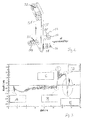
- Fig. 1 shows in a perspective view of a towing vehicle 10, which has a three-wheeled chassis 12.
- the vehicle has a standing platform 14 with a backrest 16.
- Standing on the standing platform 10 an operator can control the towing vehicle via an operating element 18.
- the direction of travel and the driving speed can be specified.
- a trailer hitch 22 is provided for a vehicle to be towed.
- Fig. 2 shows a schematic view of a possible trailer coupling 22, in which two projecting trailer plates 24, 26 are arranged opposite to each other and have a mutually aligned through hole 28.
- the trailer drawbar with an end-side eyelet (not shown) between the trailer plates 24 and 26 is arranged and fastened via a guided through the opening 28 locking bolt.
- the trailer hitch 22 is mounted on an adapter plate 30.
- the opposite side of the adapter plate 30 carries a pivot bearing 32 and a connecting plate 34.
- a strain gauge 36 is arranged as a force measuring device.
- the pivot bearing 32 is pivotally mounted via the pin 38 in a corresponding opening on the drive member.
- the adapter plate 30 is mounted substantially difficult to steer on the drive part.
- the force acting on the trailer hitch 22 tensile force Z causes the pivot bearing pivotal movement of the adapter plate.
- the adapter plate is then connected to the trailing vehicle, so that the resulting from the tensile force Z rotational movement is introduced via the connecting plate 34 in the vehicle.
- the force is conducted through the strain gauge 36 as a force measuring device, wherein the strain gauge 36 detects both the pressure forces directed towards the drive part and the traction forces pointing away from the drive part.
- a particular advantage of the illustrated adapter 30 is that it can be retrofitted to vehicles in principle. For this purpose, only a suitable abutment for the pivot bearing 32 is required and a connection for the connecting tab 34th
- Fig. 3 shows in a train with two trailers a typical course of the force occurring.
- the measuring process starts by a signal from the standing platform 14 or a seat switch as soon as the driver enters the vehicle or sits on the seat.
- This signal is a brief evaluation of the Strain gauge strip 36 started.
- the value serves as the reference value / zero value for the later measurements.
- By actuating the travel switch the measurement required to determine the load is started.
- the strain gauge 36 has a variable depending on the applied force electrical resistance, which can be detected by a suitable electrical circuit (bridge circuit). Taking into account material characteristics, the geometric measurements of tab and adapter, the strain detected on the strain gauge 36 can be converted into a corresponding force.
- Fig. 3 shows the course of force over time, at the time A, the pressing of the two trailers takes place, in which the first standing supporters set in motion.
- an emergency stop takes place at time B for abrupt deceleration of the vehicle.
- the emergency leads in C for driving the trailer on the towing vehicle.
- a force pushing the vehicle is transmitted and the vehicle comes to a standstill at time D, so that the attacking force abates abruptly.
- the stoppage of the vehicle then leads to a pendulum motion of the two trailers, which causes the change of sign of the attacking force in the time domain E.
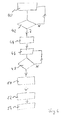
- Fig. 4 shows a flowchart in which in step 40, a system activation takes place. This is done by a query of the platform, whether it was entered or by a seat switch, if someone has taken on the seat. The initialization triggers an activation of the force measuring device for a measurement process. Also takes a brake measurement.
- step 42 the driver is queried whether an actuation of the drive switch or the accelerator pedal has occurred. If the operation is not present, the system for system activation and Referenzwertska returns in step 40. If the drive switch has been actuated, a smoothing of the measured values takes place in step 44 and a processing, for example by averaging, for a comparison. In method step 46, the smoothed and processed measured values are compared with the reference measured value from method step 40. In query 48 it is determined whether the measured values have exceeded a predetermined limit. If this is not the case, the measuring process is continued. If this is the case, then in method step 50, a driving parameter, for example the driving parameter for the maximum driving speed, is reduced.
- a driving parameter for example the driving parameter for the maximum driving speed
- step 52 the reduced driving parameter is stored in the driving control for a further control of the vehicle.
- step 54 the vehicle returns to a standby mode, from which, for example, the adaptation of the driving parameters can be repeated or monitored.
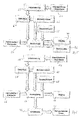
- Fig. 5 shows in a block diagram the essential process steps.
- an activation takes place, which can take place depending on the design of the truck by entering the stand platform or a seated on a seat (triggering the seat switch).
- a value of the strain gauge is recorded in method section 60.
- the value of the strain gauge is the value output by the strain gauge, which corresponds to a tensile force.
- the value of the strain gauge is reset in step 62 by selecting a present value as the zero value.
- the evaluation of the acquired measured values 60 takes place. The evaluation is triggered by actuating the travel switch or the accelerator pedal in step 66. The evaluation 64 can also use stored comparison values 68. As a result of the evaluation, the tensile force applied to the vehicle can be displayed in step 70. If a maximum permissible value for the tensile force is exceeded, a warning light can be triggered in method step 72.
- Fig. 6 shows the sequence of a method in which takes place instead of the operation of a warning light in step 72, an intervention in the driving parameters.
- the results of the evaluation 64 are applied to a switching stage 74 which, when a predetermined maximum value for the tractive force is exceeded, reduces the driving parameter for the maximum permissible driving speed V max in method step 76.
- the trailing vehicle travels at a lower maximum speed when excessive traction over the trailer hitch acts on the vehicle.
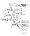
- Fig. 7 shows a further embodiment in which in each case a different maximum travel speed V max1 , V max2 or V max3 can be selected in steps 82, 84 and 86.
- the different switching stages 74 are controlled by the comparison step 80, wherein a plurality of different comparison values 68 are present at the comparison step 80. For a better classification of the measured tensile force, the data are smoothed in step 78 before the comparison 80.
Abstract
Description
- Die vorliegende Erfindung betrifft ein Flurförderzeug mit einem Antriebsteil, das eine Anhängerkupplung zum Ankuppeln eines Anhängers aufweist. Bevorzugt betrifft die vorliegende Erfindung ein Schleppfahrzeug, wie es bei der Bildung eines Routenzuges oder eines Schleppzuges zum Einsatz kommt.
- Bisher bekannte Schleppzüge werden aus einem oder mehreren Schleppern und mit diesen verbundenen Anhängern gebildet. Hierbei hat sich herausgestellt, dass, je höher die Anhängerlast und je mehr Anhänger in dem Zug geschleppt werden, umso schwieriger die Handhabung des Zuges durch das Schleppfahrzeug ist, insbesondere das Abbremsen. Auch lässt die Kurvenstabilität des Schleppzuges mit zunehmender Menge und Last in dem Schleppzug nach. Bei bekannten Schleppfahrzeugen ist es daher üblich, wenn diese für den Einsatz mit vielen oder schwer beladenen Anhängern vorgesehen sind, die maximal zulässige Endgeschwindigkeit des Schleppers zu drosseln.
- Der Erfindung liegt die Aufgabe zugrunde, ein Flurförderzeug, insbesondere einen Schlepper, bereitzustellen, bei dem eine Drosselung der Endgeschwindigkeit vermieden, aber gleichwohl eine hohe maximal zulässige Endgeschwindigkeit erreicht werden kann.
- Erfindungsgemäß wird die Aufgabe durch ein Flurförderzeug mit den Merkmalen aus Anspruch 1 gelöst. Vorteilhafte Ausgestaltungen sind in den Unteransprüchen beschrieben.
- Das erfindungsgemäße Flurförderzeug besitzt ein Antriebsteil, das eine Anhängerkupplung zum Ankoppeln eines Anhängers aufweist. Die Anhängerkupplung ist starr auf einem Adapter montiert. Erfindungsgemäß ist der Adapter an dem Antriebsteil derart montiert, dass eine an der Anhängerkupplung angreifende, von dem Antriebsteil fortweisende Zugkraft über eine Kraftmesseinrichtung erfasst und in das Antriebsteil eingeleitet wird. Die starr auf dem Adapter vorgesehene Anhängerkupplung nimmt die angreifenden Zugkräfte, also die von dem Antriebsteil fortweisenden horizontalen Kräfte auf und leitet diese über die Kraftmesseinrichtung in das Antriebsteil ein. Hierdurch liegt in dem Antriebsteil des Flurförderzeugs die gemessene Zugkraft für das Schleppfahrzeug vor und kann somit bei der Steuerung des Flurförderzeugs berücksichtigt werden. Neben der von dem Antriebsteil fortweisenden Zugkraft kann die Kraftmesseinrichtung bevorzugt auch die zu dem Antriebsteil gerichtete Druckkraft messen.
- Erfindungsgemäß ist der Adapter als eine Platte ausgebildet, auf deren ersten Flachseite die Anhängerkupplung befestigt ist und auf deren gegenüberliegenden Flachseite ein Drehlager und ein Verbindungselement angeordnet sind. Über das Drehlager ist die Platte schwenkbar an dem Antriebsteil gelagert. Eine an dem Adapter angreifende Zugkraft kann somit über das Verbindungselement von der Adapterplatte in das Antriebsteil des Fahrzeugs eingeleitet werden, wobei die Zugkraft über die Kraftmesseinrichtung in das Antriebsteil eingeleitet und gemessen wird. Indem das Drehlager nicht gegenüberliegend zu der Anhängerkupplung an dem Adapter angeordnet ist, sondern versetzt hierzu, wird durch das Drehlager ein Drehmoment auf die Platte und somit auf das Verbindungselement ausgeübt. Bei der Verwendung des Drehlagers ist für die Kraftmessung zu berücksichtigen, dass die an dem Adapter angreifende Zugkraft und die von der Kraftmesseinrichtung erfasste Kraft aufgrund des übertragenen Drehmoments in einem Verhältnis zueinander stehen, das umgekehrt zu dem Verhältnis der Abstände der Kräfte zu dem Drehpunkt ist. Über die Wahl der Abstände besteht zudem der Vorteil, die angreifenden Zugkräfte durch geeignete Wahl der Abstände in den Messbereich der Kraftmesseinrichtung zu übersetzen.
- In einer bevorzugten Ausgestaltung ist das Verbindungselement als eine Lasche ausgebildet, die mit dem Antriebsteil verbindbar ist. Bevorzugt ist eine Kraftmesseinrichtung auf oder an dem Verbindungselement angeordnet. Die Kraftmesseinrichtung erfasst den Teil der Kraft, der über das Verbindungselement in das Antriebsteil des Fahrzeugs eingeleitet wird. Aus den geometrischen Verhältnissen an der Anhängerkupplung und der Platte kann aus der gemessenen Kraft auch auf die Zugkraft zurückgerechnet werden.
- In einer bevorzugten Ausgestaltung weist die Kraftmesseinrichtung eine Anzeige auf, die eine an der Anhängerkupplung gemessene Zugkraft anzeigt. Die Anzeige für die Zugkraft ist bevorzugt im Sichtfeld des Fahrzeugführers vorgesehen, so dass der Fahrzeugführer die auf sein schleppendes Fahrzeug ausgeübte Zugkraft gut sichtbar erfassen kann.
- Neben der Möglichkeit, dass es dem Fahrer überlassen ist, aufgrund der Werte für die an seinem schleppenden Fahrzeug angreifenden Zugkräfte zu reagieren, gibt es auch die Ausgestaltung, bei der eine Fahrzeugsteuerung vorgesehen ist, die ansprechend auf gemessene Werte der Kraftmesseinrichtung die Steuerung des Fahrzeugs beeinflusst. Bevorzugt sind hierzu in der Fahrzeugsteuerung ein oder mehrere der folgenden Fahrparameter gespeichert: maximale Fahrgeschwindigkeit, maximale Fahrbeschleunigung und minimaler Kurvenradius. Diese Fahrparameter beeinflussen das Fahrverhalten des Fahrzeugs und werden abhängig von dem gemessenen Wert für die Zugkraft angepasst. Stellt das schleppende Fahrzeug fest, dass eine große Zugkraft aufgebracht werden muss, so können die für die Fahrsicherheit relevanten Fahrparameter, wie beispielsweise die maximale Fahrgeschwindigkeit, die maximale Fahrbeschleunigung und der minimale Kurvenradius, angepasst werden. Bevorzugt reduziert die Fahrzeugsteuerung mindestens einen Fahrparameter, wenn der gemessene Wert für die Zugkraft einen vorbestimmten Maximalwert überschreitet. In dieser Ausgestaltung lässt die Fahrzeugsteuerung es zu, dass das erfindungsgemäße Flurförderzeug, beispielsweise bei geringer Zugkraft, mit einer höheren Endgeschwindigkeit fährt als bei einer höheren an dem Flurförderzeug angreifenden Zugkraft. Voll beladene Anhänger werden somit langsamer als leere Anhänger geschleppt. Ebenso werden bei einer Fahrt entgegen einer Steigung die maximale Geschwindigkeit, die maximale Beschleunigung und/oder der minimale Kurvenradius reduziert.
- In einer weiteren bevorzugten Ausgestaltung sind in der Fahrzeugsteuerung mehrere Fahrprogramme abgelegt, in denen jeweils ein oder mehrere Fahrparameter in einem Fahrprogramm zusammengefasst sind, wobei die Fahrzeugsteuerung entsprechend einem gemessenen Wert für die Zugkraft eines der Fahrprogramme auswählt. In der erfindungsgemäßen Ausgestaltung werden also nicht vorgegebene Parameter in ihrem Wert verändert, sondern entsprechend der erfassten Zugkraft wird ein Fahrprogramm mit einem geeigneten Satz von Fahrparametern ausgewählt.
- In einer bevorzugten Ausgestaltung misst die Kraftmesseinrichtung bei stehendem und bei schleppendem Fahrzeug, wobei aus einer Veränderung der Messwerte die Zugkraft bestimmt wird.
- Die Erfindung wird anhand der nachfolgenden Ausführungsbeispiele näher erläutert. Es zeigen:
- Fig. 1
- einen Schlepper in einer perspektivischen Ansicht,
- Fig. 2
- einen Adapter mit Anhängerkupplung in einer schematischen Ansicht von der Seite,
- Fig. 3
- den Verlauf der Zugkraft über der Zeit,
- Fig. 4
- ein Flussdiagramm zu dem in der Fahrzeugsteuerung ausgeführten Verfahren,
- Fig. 5
- ein Blockdiagramm zur Auswertung der Messwerte,
- Fig. 6
- ein alternatives Blockdiagramm mit einer Einstellung eines Fahrparameters und
- Fig. 7
- ein alternatives Blockdiagramm zur Einstellung von mehreren Fahrparametern.
-
Fig. 1 zeigt in einer perspektivischen Ansicht ein Schleppfahrzeug 10, das ein dreirädriges Fahrwerk 12 besitzt. Das Fahrzeug besitzt eine Standplattform 14 mit einer Rückenlehne 16. Auf der Standplattform 10 stehend kann eine Bedienperson über ein Bedienelement 18 das Schleppfahrzeug steuern. Hierbei können beispielsweise die Fahrtrichtung und die Fahrgeschwindigkeit vorgegeben werden. - Auf der nach hinten weisenden Rückwand 20 des Schleppfahrzeugs ist eine Anhängerkupplung 22 für ein zu schleppendes Fahrzeug vorgesehen.
-
Fig. 2 zeigt in einer schematischen Ansicht eine mögliche Anhängerkupplung 22, bei der zwei vorstehende Anhängerplatten 24, 26 einander gegenüberliegend angeordnet sind und eine miteinander fluchtende Durchgangsbohrung 28 besitzen. - Zur Befestigung des Anhängers wird die Anhängerdeichsel mit einer endseitigen Öse (nicht dargestellt) zwischen den Anhängerplatten 24 und 26 angeordnet und über einen durch die Öffnung 28 geführten Verriegelungsbolzen befestigt. Die Anhängerkupplung 22 ist auf einer Adapterplatte 30 montiert. Die gegenüberliegende Seite der Adapterplatte 30 trägt ein Drehlager 32 und eine Verbindungslasche 34. Auf der Verbindungslasche 34 ist ein Dehnungsmessstreifen 36 als Kraftmesseinrichtung angeordnet. Zur Befestigung der Adapterplatte 30 an dem schleppenden Fahrzeug wird das Drehlager 32 über den Zapfen 38 in einer entsprechenden Öffnung an dem Antriebsteil schwenkbar befestigt. Dabei ist die Adapterplatte 30 im Wesentlichen schwer lenkbar an dem Antriebsteil angebracht. Die an der Anhängerkupplung 22 angreifende Zugkraft Z bewirkt am Drehlager eine Schwenkbewegung der Adapterplatte. Über die Verbindungslasche 34 ist die Adapterplatte dann mit dem schleppenden Fahrzeug verbunden, so dass die durch die Zugkraft Z entstehende Drehbewegung über die Verbindungslasche 34 in das Fahrzeug eingeleitet wird. Hierbei wird die Kraft durch den Dehnungsmessstreifen 36 als Kraftmesseinrichtung geleitet, wobei der Dehnungsmessstreifen 36 sowohl die zu dem Antriebsteil hin gerichteten Druckkräfte als auch die von dem Antriebsteil fortweisenden Zugkräfte erfasst.
- Ein besonderer Vorteil des dargestellten Adapters 30 besteht darin, dass dieser grundsätzlich an Fahrzeugen nachgerüstet werden kann. Hierzu ist lediglich ein geeignetes Gegenlager für das Drehlager 32 erforderlich und eine Anbindung für die Verbindungslasche 34.
-
Fig. 3 zeigt bei einem Zug mit zwei Anhängern einen typischen Verlauf der auftretenden Kraft. Der Messvorgang startet durch ein Signal von der Standplattform 14 oder von einem Sitzschalter, sobald der Fahrer das Fahrzeug betritt oder auf dem Sitz Platz nimmt. Durch dieses Signal wird eine kurze Auswertung des Dehnungsmessstreifens 36 gestartet. Der Wert dient als Referenzwert/Nullwert für die späteren Messungen. Durch eine Betätigung des Fahrschalters wird die zur Bestimmung der Last notwendige Messung gestartet. Der Dehnungsmessstreifen 36 besitzt einen abhängig von der angreifenden Kraft veränderlichen elektrischen Widerstand, der durch eine geeignete elektrische Schaltung (Brückenschaltung) erfasst werden kann. Unter Berücksichtigung von Materialkennwerten, den geometrischen Messungen von Lasche und Adapter, kann die an dem Dehnungsmessstreifen 36 erfasste Dehnung in eine entsprechende Kraft umgerechnet werden. -
Fig. 3 zeigt den Kraftverlauf über der Zeit, wobei zum Zeitpunkt A das Anrucken der beiden Anhänger erfolgt, bei dem die zunächst stehenden Anhänger sich in Bewegung setzen. In dem dargestellten Beispiel erfolgt zum Zeitpunkt B ein Notaus zum abrupten Abbremsen des Fahrzeugs. Das Notaus führt in C zum Auffahren der Anhänger auf das schleppende Fahrzeug. Hierdurch wird eine das Fahrzeug schiebende Kraft übertragen und das Fahrzeug kommt im Zeitpunkt D zum Stillstand, so dass die angreifende Kraft abrupt nachlässt. Der Stillstand des Fahrzeugs führt dann zu einer Pendelbewegung der beiden Anhänger, die den Vorzeichenwechsel der angreifenden Kraft im Zeitbereich E verursacht. - Das vorstehende Beispiel macht deutlich, dass für eine zuverlässige Signalverarbeitung, die gemessenen Werte geglättet werden müssen.
-
Fig. 4 zeigt ein Flussdiagramm, bei dem in Verfahrensschritt 40 eine Systemaktivierung erfolgt. Diese erfolgt durch eine Abfrage der Standplattform, ob diese betreten wurde oder durch einen Sitzschalter, ob jemand auf dem Sitz Platz genommen hat. Die Initialisierung löst eine Aktivierung der Kraftmesseinrichtung für einen Messvorgang aus. Ebenfalls erfolgt eine Bremsmessung. - In Verfahrensschritt 42 wird der Fahrschalter abgefragt, ob eine Betätigung des Fahrschalters oder des Fahrpedals erfolgt ist. Liegt die Betätigung nicht vor, so kehrt das System zur Systemaktivierung und Referenzwertmessung in Schritt 40 zurück. Ist der Fahrschalter betätigt worden, so erfolgt in Schritt 44 eine Glättung der gemessenen Werte und eine Aufbereitung, beispielsweise durch Mittelwertbildung, für einen Vergleich. In Verfahrensschritt 46 werden die geglätteten und aufbereiteten Messwerte mit dem Referenzmesswert aus dem Verfahrensschritt 40 verglichen. In Abfrage 48 wird festgestellt, ob die gemessenen Werte einen vorgegebenen Grenzwert überschritten haben. Ist dies nicht der Fall, so wird der Messvorgang fortgesetzt. Ist dies der Fall, so wird in Verfahrensschritt 50 ein Fahrparameter, beispielsweise der Fahrparameter für die maximale Fahrgeschwindigkeit herabgesetzt.
- In Verfahrensschritt 52 wird der herabgesetzte Fahrparameter in der Fahrsteuerung für eine weitere Ansteuerung des Fahrzeugs gespeichert. In Verfahrensschritt 54 kehrt das Fahrzeug in einen Bereitschaftsmodus zurück, von dem aus beispielsweise die Anpassung der Fahrparameter wiederholt oder überwacht werden kann.
-
Fig. 5 zeigt in einem Blockdiagramm die wesentlichen Verfahrensschritte. In Verfahrensschritt 56 erfolgt eine Aktivierung, die je nach Ausgestaltung des Flurförderzeugs durch ein Betreten der Standplattform oder ein Platznehmen auf einem Sitz erfolgen kann (Auslösen des Sitzschalters). - In einem nachfolgenden Schritt 58 erfolgt die Initialisierung des Verfahrens. Nachfolgend zur Initialisierung des Verfahrens wird ein Wert des Dehnungsmessstreifens in Verfahrensschnitt 60 aufgenommen. Der Wert des Dehnungsmessstreifens ist der von dem Dehnungsmessstreifen ausgegebene Wert, der einer Zugkraft entspricht. Zu Beginn des Verfahrens wird der Wert des Dehnungsmessstreifens in Verfahrensschritt 62 zurückgesetzt, indem ein vorliegender Wert als Nullwert ausgewählt wird. In Verfahrensschritt 64 erfolgt die Auswertung der gewonnenen Messwerte 60. Die Auswertung wird durch ein Betätigen des Fahrschalters oder des Fahrpedals in Schritt 66 ausgelöst. Die Auswertung 64 kann ebenfalls gespeicherte Vergleichswerte 68 heranziehen. Als Ergebnis der Auswertung kann die an dem Fahrzeug anliegende Zugkraft in Schritt 70 angezeigt werden. Bei Überschreiten eines maximal zulässigen Wertes für die Zugkraft kann in Verfahrensschritt 72 eine Warnleuchte ausgelöst werden.
- Bei der in
Fig. 5 dargestellten Variante erfolgt kein Eingriff in die Fahrparameter. -
Fig. 6 zeigt den Ablauf eines Verfahrens, bei dem statt der Betätigung einer Warnleuchte in Schritt 72, ein Eingriff in die Fahrparameter erfolgt. Hierzu liegen die Ergebnisse der Auswertung 64 an einer Schaltstufe 74 an, die bei Überschreiten eines vorbestimmten Maximalwerts für die Zugkraft den Fahrparameter für die maximal zulässige Fahrgeschwindigkeit Vmax in Verfahrensschritt 76 herabsetzt. Bei dieser Ausgestaltung fährt das schleppende Fahrzeug mit einer geringeren Maximalgeschwindigkeit, wenn eine zu große Zugkraft über die Anhängerkupplung auf das Fahrzeug wirkt. -
Fig. 7 zeigt eine weitere Ausgestaltung, bei der in den Schritten 82, 84 und 86 jeweils eine unterschiedliche maximale Fahrgeschwindigkeit Vmax1, Vmax2 oder Vmax3 ausgewählt werden kann. Die unterschiedlichen Schaltstufen 74 werden durch den Vergleichsschritt 80 angesteuert, wobei an dem Vergleichsschritt 80 mehrere unterschiedliche Vergleichswerte 68 anliegen. Zur besseren Einordnung der gemessenen Zugkraft werden vor dem Vergleich 80 die Daten in Schritt 78 geglättet.
Claims (8)
- Flurförderzeug mit einem Antriebsteil, das eine Anhängerkupplung zum Ankuppeln eines Anhängers aufweist, dadurch gekennzeichnet, dass die Anhängerkupplung starr auf einem Adapter und der Adapter an dem Antriebsteil derart montiert ist, dass eine an der Anhängerkupplung angreifende, von dem Antriebsteil fortweisende Zugkraft über eine Kraftmesseinrichtung in das Antriebsteil eingeleitet wird, wobei der Adapter als eine Platte ausgebildet ist, auf deren erste Flachseite die Anhängerkupplung befestigt ist und auf deren gegenüberliegenden Flachseite ein Drehlager und ein Verbindungselement angeordnet sind.
- Flurförderzeug nach Anspruch 1, dadurch gekennzeichnet, dass das Verbindungselement als längliche Lasche ausgebildet ist, die mit dem Antriebsteil verbindbar ist.
- Flurförderzeug nach Anspruch 1 oder 2, dadurch gekennzeichnet, dass die Kraftmesseinrichtung auf oder an dem Verbindungselement angeordnet ist.
- Flurförderzeug nach einem der Ansprüche 1 bis 3, dadurch gekennzeichnet, dass die Kraftmesseinrichtung eine Anzeige aufweist, die eine an der Anhängerkupplung gemessene Zugkraft anzeigt.
- Flurförderzeug nach einem der Ansprüche 1 bis 4, dadurch gekennzeichnet, dass eine Fahrzeugsteuerung vorgesehen ist, in der mindestens einer der nachfolgenden Fahrparameter gespeichert ist: maximale Fahrgeschwindigkeit, maximale Fahrbeschleunigung und minimaler Kurvenradius, wobei die Fahrzeugsteuerung, abhängig von dem gemessenen Wert für die Zugkraft mindestens einen Fahrparameter anpasst.
- Flurförderzeug nach Anspruch 5, dadurch gekennzeichnet, dass die Fahrzeugsteuerung mindestens einen Fahrparameter reduziert, wenn der gemessene Wert für die Zugkraft eine vorbestimmten Maximalwert überschreitet.
- Flurförderzeug nach Anspruch 5 oder 6, dadurch gekennzeichnet, dass in der Fahrzeugsteuerung mehrere Fahrprogramme abgelegt sind, in denen ein oder mehrere Fahrparameter zu einem Fahrprogramm zusammengefasst sind, wobei die Fahrzeugsteuerung entsprechend einem gemessenen Wert für die Zugkraft eines der Fahrprogramme auswählt.
- Flurförderzeug nach einem der Ansprüche 1 bis 7, dadurch gekennzeichnet, dass die Kraftmesseinrichtung bei stehendem Fahrzeug und bei schleppendem Fahrzeug misst und aus der Veränderung der Messwerte die Zugkraft bestimmt.
Applications Claiming Priority (1)
| Application Number | Priority Date | Filing Date | Title |
|---|---|---|---|
| DE102013008705.8A DE102013008705A1 (de) | 2013-05-18 | 2013-05-18 | Flurförderzeug mit Anhängerkupplung |
Publications (2)
| Publication Number | Publication Date |
|---|---|
| EP2803618A1 true EP2803618A1 (de) | 2014-11-19 |
| EP2803618B1 EP2803618B1 (de) | 2017-10-25 |
Family
ID=50721690
Family Applications (1)
| Application Number | Title | Priority Date | Filing Date |
|---|---|---|---|
| EP14168614.7A Not-in-force EP2803618B1 (de) | 2013-05-18 | 2014-05-16 | Flurförderzeug mit Anhängerkupplung |
Country Status (2)
| Country | Link |
|---|---|
| EP (1) | EP2803618B1 (de) |
| DE (1) | DE102013008705A1 (de) |
Families Citing this family (6)
| Publication number | Priority date | Publication date | Assignee | Title |
|---|---|---|---|---|
| EP3379222B1 (de) | 2017-03-22 | 2020-12-30 | Methode Electronics Malta Ltd. | Auf magnetoelastik basierte sensoranordnung |
| US11491832B2 (en) | 2018-02-27 | 2022-11-08 | Methode Electronics, Inc. | Towing systems and methods using magnetic field sensing |
| US11135882B2 (en) | 2018-02-27 | 2021-10-05 | Methode Electronics, Inc. | Towing systems and methods using magnetic field sensing |
| US11221262B2 (en) | 2018-02-27 | 2022-01-11 | Methode Electronics, Inc. | Towing systems and methods using magnetic field sensing |
| US11084342B2 (en) | 2018-02-27 | 2021-08-10 | Methode Electronics, Inc. | Towing systems and methods using magnetic field sensing |
| US10670479B2 (en) | 2018-02-27 | 2020-06-02 | Methode Electronics, Inc. | Towing systems and methods using magnetic field sensing |
Citations (2)
| Publication number | Priority date | Publication date | Assignee | Title |
|---|---|---|---|---|
| AU2008264181A1 (en) * | 2007-12-24 | 2009-07-09 | Michael Maud | Releasable Tow Hitch |
| EP2492162A2 (de) * | 2011-02-25 | 2012-08-29 | STILL GmbH | Schlepper |
Family Cites Families (5)
| Publication number | Priority date | Publication date | Assignee | Title |
|---|---|---|---|---|
| DE4419673C2 (de) * | 1994-06-07 | 1998-03-12 | Hottinger Messtechnik Baldwin | Anhängerkupplung mit einem Kraftaufnehmer |
| DE102006022744B4 (de) * | 2006-05-12 | 2015-07-16 | Linde Material Handling Gmbh | Flurförderzeug mit einer Anhängevorrichtung |
| DE102008018376A1 (de) * | 2008-04-11 | 2009-10-15 | Still Sas | Schlepper |
| US8380390B2 (en) * | 2009-06-24 | 2013-02-19 | Robert Bosch Gmbh | Method and system of determining load characteristics of a trailer |
| EP3357717B2 (de) * | 2011-11-03 | 2023-11-22 | WESTFALIA - Automotive GmbH | Anhängekupplung mit einer auswerteeinrichtung |
-
2013
- 2013-05-18 DE DE102013008705.8A patent/DE102013008705A1/de not_active Withdrawn
-
2014
- 2014-05-16 EP EP14168614.7A patent/EP2803618B1/de not_active Not-in-force
Patent Citations (2)
| Publication number | Priority date | Publication date | Assignee | Title |
|---|---|---|---|---|
| AU2008264181A1 (en) * | 2007-12-24 | 2009-07-09 | Michael Maud | Releasable Tow Hitch |
| EP2492162A2 (de) * | 2011-02-25 | 2012-08-29 | STILL GmbH | Schlepper |
Also Published As
| Publication number | Publication date |
|---|---|
| EP2803618B1 (de) | 2017-10-25 |
| DE102013008705A1 (de) | 2014-11-20 |
Similar Documents
| Publication | Publication Date | Title |
|---|---|---|
| EP2803618B1 (de) | Flurförderzeug mit Anhängerkupplung | |
| EP2714436B1 (de) | Anordnung zur verbindung eines zugfahrzeugs mit einem anhänger | |
| DE19901953B4 (de) | Vorrichtung und Verfahren zur Stabilisierung eines Fahrzeuggespannes | |
| EP1612081B1 (de) | Verfahren und Vorrichtung zum Betreiben eines Kraftfahrzeuges mit einer Anhängekupplung | |
| EP0188685B1 (de) | Überlast-Schutz- und/oder -Warneinrichtung | |
| WO2008000558A1 (de) | Regel- und steuersystem in einem fahrzeugverbund | |
| DE102011003791A1 (de) | System zum automatischen Einstellen eines Spaltraumes zwischen einem Motorwagen und einem daran angekuppelten Anhänger | |
| EP2781403B1 (de) | Vorrichtung und Verfahren zur Überwachung der Entladung eines Kippfahrzeuges | |
| EP3515796B1 (de) | Verfahren zur erkennung und/oder steuerung eines ankupplungsvorgangs zwischen einem zugfahrzeug und einem fahrzeuganhänger | |
| DE3126128A1 (de) | Anordnung zum begrenzen unkontrollierter winkelbewegungen im gelenk zwischen fahrzeugeinheiten von gelenkfahrzeugen, insbesondere gelenkomnibussen | |
| DE3742996A1 (de) | Ueberlast-warneinrichtung fuer eine anhaengerbremse | |
| EP2123528B1 (de) | Fahrzeugkombination mit einer Streckbremsvorrichtung | |
| DE102018122224B4 (de) | System zur Überwachung einer Kopplung sowie eine Stützeinheit | |
| EP3753758B1 (de) | Kupplungsvorrichtung für fahrzeuganhänger mit einer anhängerseitigen zugkugelkupplung | |
| DE4007610C2 (de) | Meß- bzw. Überwachungseinrichtung für kraftbeanspruchte Teile | |
| EP2353970B1 (de) | Zwangslenkung | |
| EP2868500B1 (de) | System zur Erfassung einer Änderung einer Achseinstellung eines Kraftfahrzeugs | |
| DE102016208618A1 (de) | Verfahren zur Ermittlung der auf ein Zugfahrzeug an dessen Anhängerkupplung wirkenden Stützlast nach dem Ankuppeln eines Anhängers | |
| DE202005019223U1 (de) | Auflaufbremsanlage für Kraftfahrzeuganhänger mit Wegmesseinrichtung für Zugstange | |
| DE102020126622B4 (de) | Bestimmen der fahrzeug- und anhängelast | |
| DE102021112071A1 (de) | Verfahren zum Überwachen einer Kupplungsverbindung zwischen Teilfahrzeugen eines Fahrzeug-Gespanns sowie Fahrzeug-Gespann | |
| DE10197123B4 (de) | Verfahren und System für Bremsen von Nutzfahrzeugen | |
| DE10230309B4 (de) | Vorrichtung für Kraftfahrzeuge für Lenkkraftüberwachung | |
| EP3144646B1 (de) | Kraftfahrzeug und verfahren zur ermittlung einer radaufstandskraft für jedes rad eines kraftfahrzeugs | |
| DE2806751A1 (de) | Vorrichtung zum sperren des gelenks von gelenkfahrzeugen |
Legal Events
| Date | Code | Title | Description |
|---|---|---|---|
| PUAI | Public reference made under article 153(3) epc to a published international application that has entered the european phase |
Free format text: ORIGINAL CODE: 0009012 |
|
| 17P | Request for examination filed |
Effective date: 20140516 |
|
| AK | Designated contracting states |
Kind code of ref document: A1 Designated state(s): AL AT BE BG CH CY CZ DE DK EE ES FI FR GB GR HR HU IE IS IT LI LT LU LV MC MK MT NL NO PL PT RO RS SE SI SK SM TR |
|
| AX | Request for extension of the european patent |
Extension state: BA ME |
|
| R17P | Request for examination filed (corrected) |
Effective date: 20150423 |
|
| RBV | Designated contracting states (corrected) |
Designated state(s): AL AT BE BG CH CY CZ DE DK EE ES FI FR GB GR HR HU IE IS IT LI LT LU LV MC MK MT NL NO PL PT RO RS SE SI SK SM TR |
|
| GRAP | Despatch of communication of intention to grant a patent |
Free format text: ORIGINAL CODE: EPIDOSNIGR1 |
|
| INTG | Intention to grant announced |
Effective date: 20170515 |
|
| GRAS | Grant fee paid |
Free format text: ORIGINAL CODE: EPIDOSNIGR3 |
|
| GRAA | (expected) grant |
Free format text: ORIGINAL CODE: 0009210 |
|
| AK | Designated contracting states |
Kind code of ref document: B1 Designated state(s): AL AT BE BG CH CY CZ DE DK EE ES FI FR GB GR HR HU IE IS IT LI LT LU LV MC MK MT NL NO PL PT RO RS SE SI SK SM TR |
|
| RAP1 | Party data changed (applicant data changed or rights of an application transferred) |
Owner name: JUNGHEINRICH AKTIENGESELLSCHAFT |
|
| REG | Reference to a national code |
Ref country code: GB Ref legal event code: FG4D Free format text: NOT ENGLISH |
|
| REG | Reference to a national code |
Ref country code: CH Ref legal event code: EP |
|
| REG | Reference to a national code |
Ref country code: AT Ref legal event code: REF Ref document number: 939708 Country of ref document: AT Kind code of ref document: T Effective date: 20171115 |
|
| REG | Reference to a national code |
Ref country code: IE Ref legal event code: FG4D Free format text: LANGUAGE OF EP DOCUMENT: GERMAN |
|
| REG | Reference to a national code |
Ref country code: DE Ref legal event code: R096 Ref document number: 502014005934 Country of ref document: DE |
|
| REG | Reference to a national code |
Ref country code: NL Ref legal event code: MP Effective date: 20171025 |
|
| REG | Reference to a national code |
Ref country code: LT Ref legal event code: MG4D |
|
| PG25 | Lapsed in a contracting state [announced via postgrant information from national office to epo] |
Ref country code: NL Free format text: LAPSE BECAUSE OF FAILURE TO SUBMIT A TRANSLATION OF THE DESCRIPTION OR TO PAY THE FEE WITHIN THE PRESCRIBED TIME-LIMIT Effective date: 20171025 |
|
| PG25 | Lapsed in a contracting state [announced via postgrant information from national office to epo] |
Ref country code: SE Free format text: LAPSE BECAUSE OF FAILURE TO SUBMIT A TRANSLATION OF THE DESCRIPTION OR TO PAY THE FEE WITHIN THE PRESCRIBED TIME-LIMIT Effective date: 20171025 Ref country code: LT Free format text: LAPSE BECAUSE OF FAILURE TO SUBMIT A TRANSLATION OF THE DESCRIPTION OR TO PAY THE FEE WITHIN THE PRESCRIBED TIME-LIMIT Effective date: 20171025 Ref country code: NO Free format text: LAPSE BECAUSE OF FAILURE TO SUBMIT A TRANSLATION OF THE DESCRIPTION OR TO PAY THE FEE WITHIN THE PRESCRIBED TIME-LIMIT Effective date: 20180125 Ref country code: FI Free format text: LAPSE BECAUSE OF FAILURE TO SUBMIT A TRANSLATION OF THE DESCRIPTION OR TO PAY THE FEE WITHIN THE PRESCRIBED TIME-LIMIT Effective date: 20171025 |
|
| REG | Reference to a national code |
Ref country code: FR Ref legal event code: PLFP Year of fee payment: 5 |
|
| PG25 | Lapsed in a contracting state [announced via postgrant information from national office to epo] |
Ref country code: HR Free format text: LAPSE BECAUSE OF FAILURE TO SUBMIT A TRANSLATION OF THE DESCRIPTION OR TO PAY THE FEE WITHIN THE PRESCRIBED TIME-LIMIT Effective date: 20171025 Ref country code: GR Free format text: LAPSE BECAUSE OF FAILURE TO SUBMIT A TRANSLATION OF THE DESCRIPTION OR TO PAY THE FEE WITHIN THE PRESCRIBED TIME-LIMIT Effective date: 20180126 Ref country code: BG Free format text: LAPSE BECAUSE OF FAILURE TO SUBMIT A TRANSLATION OF THE DESCRIPTION OR TO PAY THE FEE WITHIN THE PRESCRIBED TIME-LIMIT Effective date: 20180125 Ref country code: RS Free format text: LAPSE BECAUSE OF FAILURE TO SUBMIT A TRANSLATION OF THE DESCRIPTION OR TO PAY THE FEE WITHIN THE PRESCRIBED TIME-LIMIT Effective date: 20171025 Ref country code: LV Free format text: LAPSE BECAUSE OF FAILURE TO SUBMIT A TRANSLATION OF THE DESCRIPTION OR TO PAY THE FEE WITHIN THE PRESCRIBED TIME-LIMIT Effective date: 20171025 Ref country code: IS Free format text: LAPSE BECAUSE OF FAILURE TO SUBMIT A TRANSLATION OF THE DESCRIPTION OR TO PAY THE FEE WITHIN THE PRESCRIBED TIME-LIMIT Effective date: 20180225 |
|
| REG | Reference to a national code |
Ref country code: DE Ref legal event code: R097 Ref document number: 502014005934 Country of ref document: DE |
|
| PG25 | Lapsed in a contracting state [announced via postgrant information from national office to epo] |
Ref country code: DK Free format text: LAPSE BECAUSE OF FAILURE TO SUBMIT A TRANSLATION OF THE DESCRIPTION OR TO PAY THE FEE WITHIN THE PRESCRIBED TIME-LIMIT Effective date: 20171025 Ref country code: CY Free format text: LAPSE BECAUSE OF FAILURE TO SUBMIT A TRANSLATION OF THE DESCRIPTION OR TO PAY THE FEE WITHIN THE PRESCRIBED TIME-LIMIT Effective date: 20171025 Ref country code: EE Free format text: LAPSE BECAUSE OF FAILURE TO SUBMIT A TRANSLATION OF THE DESCRIPTION OR TO PAY THE FEE WITHIN THE PRESCRIBED TIME-LIMIT Effective date: 20171025 Ref country code: CZ Free format text: LAPSE BECAUSE OF FAILURE TO SUBMIT A TRANSLATION OF THE DESCRIPTION OR TO PAY THE FEE WITHIN THE PRESCRIBED TIME-LIMIT Effective date: 20171025 Ref country code: SK Free format text: LAPSE BECAUSE OF FAILURE TO SUBMIT A TRANSLATION OF THE DESCRIPTION OR TO PAY THE FEE WITHIN THE PRESCRIBED TIME-LIMIT Effective date: 20171025 |
|
| PG25 | Lapsed in a contracting state [announced via postgrant information from national office to epo] |
Ref country code: PL Free format text: LAPSE BECAUSE OF FAILURE TO SUBMIT A TRANSLATION OF THE DESCRIPTION OR TO PAY THE FEE WITHIN THE PRESCRIBED TIME-LIMIT Effective date: 20171025 Ref country code: IT Free format text: LAPSE BECAUSE OF FAILURE TO SUBMIT A TRANSLATION OF THE DESCRIPTION OR TO PAY THE FEE WITHIN THE PRESCRIBED TIME-LIMIT Effective date: 20171025 Ref country code: RO Free format text: LAPSE BECAUSE OF FAILURE TO SUBMIT A TRANSLATION OF THE DESCRIPTION OR TO PAY THE FEE WITHIN THE PRESCRIBED TIME-LIMIT Effective date: 20171025 Ref country code: SM Free format text: LAPSE BECAUSE OF FAILURE TO SUBMIT A TRANSLATION OF THE DESCRIPTION OR TO PAY THE FEE WITHIN THE PRESCRIBED TIME-LIMIT Effective date: 20171025 |
|
| PLBE | No opposition filed within time limit |
Free format text: ORIGINAL CODE: 0009261 |
|
| STAA | Information on the status of an ep patent application or granted ep patent |
Free format text: STATUS: NO OPPOSITION FILED WITHIN TIME LIMIT |
|
| PG25 | Lapsed in a contracting state [announced via postgrant information from national office to epo] |
Ref country code: MT Free format text: LAPSE BECAUSE OF FAILURE TO SUBMIT A TRANSLATION OF THE DESCRIPTION OR TO PAY THE FEE WITHIN THE PRESCRIBED TIME-LIMIT Effective date: 20171025 |
|
| 26N | No opposition filed |
Effective date: 20180726 |
|
| PG25 | Lapsed in a contracting state [announced via postgrant information from national office to epo] |
Ref country code: SI Free format text: LAPSE BECAUSE OF FAILURE TO SUBMIT A TRANSLATION OF THE DESCRIPTION OR TO PAY THE FEE WITHIN THE PRESCRIBED TIME-LIMIT Effective date: 20171025 |
|
| REG | Reference to a national code |
Ref country code: CH Ref legal event code: PL |
|
| REG | Reference to a national code |
Ref country code: BE Ref legal event code: MM Effective date: 20180531 |
|
| PG25 | Lapsed in a contracting state [announced via postgrant information from national office to epo] |
Ref country code: MC Free format text: LAPSE BECAUSE OF FAILURE TO SUBMIT A TRANSLATION OF THE DESCRIPTION OR TO PAY THE FEE WITHIN THE PRESCRIBED TIME-LIMIT Effective date: 20171025 |
|
| REG | Reference to a national code |
Ref country code: IE Ref legal event code: MM4A |
|
| PG25 | Lapsed in a contracting state [announced via postgrant information from national office to epo] |
Ref country code: LI Free format text: LAPSE BECAUSE OF NON-PAYMENT OF DUE FEES Effective date: 20180531 Ref country code: CH Free format text: LAPSE BECAUSE OF NON-PAYMENT OF DUE FEES Effective date: 20180531 |
|
| PG25 | Lapsed in a contracting state [announced via postgrant information from national office to epo] |
Ref country code: LU Free format text: LAPSE BECAUSE OF NON-PAYMENT OF DUE FEES Effective date: 20180516 |
|
| PG25 | Lapsed in a contracting state [announced via postgrant information from national office to epo] |
Ref country code: IE Free format text: LAPSE BECAUSE OF NON-PAYMENT OF DUE FEES Effective date: 20180516 |
|
| PG25 | Lapsed in a contracting state [announced via postgrant information from national office to epo] |
Ref country code: BE Free format text: LAPSE BECAUSE OF NON-PAYMENT OF DUE FEES Effective date: 20180531 |
|
| PG25 | Lapsed in a contracting state [announced via postgrant information from national office to epo] |
Ref country code: ES Free format text: LAPSE BECAUSE OF FAILURE TO SUBMIT A TRANSLATION OF THE DESCRIPTION OR TO PAY THE FEE WITHIN THE PRESCRIBED TIME-LIMIT Effective date: 20171025 |
|
| PG25 | Lapsed in a contracting state [announced via postgrant information from national office to epo] |
Ref country code: TR Free format text: LAPSE BECAUSE OF FAILURE TO SUBMIT A TRANSLATION OF THE DESCRIPTION OR TO PAY THE FEE WITHIN THE PRESCRIBED TIME-LIMIT Effective date: 20171025 |
|
| PG25 | Lapsed in a contracting state [announced via postgrant information from national office to epo] |
Ref country code: PT Free format text: LAPSE BECAUSE OF FAILURE TO SUBMIT A TRANSLATION OF THE DESCRIPTION OR TO PAY THE FEE WITHIN THE PRESCRIBED TIME-LIMIT Effective date: 20171025 Ref country code: HU Free format text: LAPSE BECAUSE OF FAILURE TO SUBMIT A TRANSLATION OF THE DESCRIPTION OR TO PAY THE FEE WITHIN THE PRESCRIBED TIME-LIMIT; INVALID AB INITIO Effective date: 20140516 |
|
| PG25 | Lapsed in a contracting state [announced via postgrant information from national office to epo] |
Ref country code: MK Free format text: LAPSE BECAUSE OF NON-PAYMENT OF DUE FEES Effective date: 20171025 |
|
| PG25 | Lapsed in a contracting state [announced via postgrant information from national office to epo] |
Ref country code: AL Free format text: LAPSE BECAUSE OF FAILURE TO SUBMIT A TRANSLATION OF THE DESCRIPTION OR TO PAY THE FEE WITHIN THE PRESCRIBED TIME-LIMIT Effective date: 20171025 |
|
| PGFP | Annual fee paid to national office [announced via postgrant information from national office to epo] |
Ref country code: FR Payment date: 20200527 Year of fee payment: 7 |
|
| REG | Reference to a national code |
Ref country code: AT Ref legal event code: MM01 Ref document number: 939708 Country of ref document: AT Kind code of ref document: T Effective date: 20190516 |
|
| PGFP | Annual fee paid to national office [announced via postgrant information from national office to epo] |
Ref country code: GB Payment date: 20200528 Year of fee payment: 7 |
|
| PGFP | Annual fee paid to national office [announced via postgrant information from national office to epo] |
Ref country code: DE Payment date: 20200728 Year of fee payment: 7 |
|
| PG25 | Lapsed in a contracting state [announced via postgrant information from national office to epo] |
Ref country code: AT Free format text: LAPSE BECAUSE OF NON-PAYMENT OF DUE FEES Effective date: 20190516 |
|
| REG | Reference to a national code |
Ref country code: DE Ref legal event code: R119 Ref document number: 502014005934 Country of ref document: DE |
|
| GBPC | Gb: european patent ceased through non-payment of renewal fee |
Effective date: 20210516 |
|
| PG25 | Lapsed in a contracting state [announced via postgrant information from national office to epo] |
Ref country code: GB Free format text: LAPSE BECAUSE OF NON-PAYMENT OF DUE FEES Effective date: 20210516 Ref country code: DE Free format text: LAPSE BECAUSE OF NON-PAYMENT OF DUE FEES Effective date: 20211201 |
|
| PG25 | Lapsed in a contracting state [announced via postgrant information from national office to epo] |
Ref country code: FR Free format text: LAPSE BECAUSE OF NON-PAYMENT OF DUE FEES Effective date: 20210531 |