EP2803524B1 - Induktionsaufladegerät für Batterie eines elektrischen Kraftfahrzeugs - Google Patents
Induktionsaufladegerät für Batterie eines elektrischen Kraftfahrzeugs Download PDFInfo
- Publication number
- EP2803524B1 EP2803524B1 EP14168036.3A EP14168036A EP2803524B1 EP 2803524 B1 EP2803524 B1 EP 2803524B1 EP 14168036 A EP14168036 A EP 14168036A EP 2803524 B1 EP2803524 B1 EP 2803524B1
- Authority
- EP
- European Patent Office
- Prior art keywords
- support
- cable
- elements
- housing
- wheels
- Prior art date
- Legal status (The legal status is an assumption and is not a legal conclusion. Google has not performed a legal analysis and makes no representation as to the accuracy of the status listed.)
- Active
Links
Images



Classifications
-
- H—ELECTRICITY
- H02—GENERATION; CONVERSION OR DISTRIBUTION OF ELECTRIC POWER
- H02J—ELECTRIC POWER NETWORKS; CIRCUIT ARRANGEMENTS OR SYSTEMS FOR SUPPLYING OR DISTRIBUTING ELECTRIC POWER; SYSTEMS FOR STORING ELECTRIC ENERGY
- H02J50/00—Circuit arrangements or systems for wireless supply or distribution of electric power
- H02J50/10—Circuit arrangements or systems for wireless supply or distribution of electric power using inductive coupling
-
- B—PERFORMING OPERATIONS; TRANSPORTING
- B60—VEHICLES IN GENERAL
- B60L—PROPULSION OF ELECTRICALLY-PROPELLED VEHICLES; SUPPLYING ELECTRIC POWER FOR AUXILIARY EQUIPMENT OF ELECTRICALLY-PROPELLED VEHICLES; ELECTRODYNAMIC BRAKE SYSTEMS FOR VEHICLES IN GENERAL; MAGNETIC SUSPENSION OR LEVITATION FOR VEHICLES; MONITORING OPERATING VARIABLES OF ELECTRICALLY-PROPELLED VEHICLES; ELECTRIC SAFETY DEVICES FOR ELECTRICALLY-PROPELLED VEHICLES
- B60L53/00—Methods of charging batteries, specially adapted for electric vehicles; Charging stations or on-board charging equipment therefor; Exchange of energy storage elements in electric vehicles
- B60L53/10—Methods of charging batteries, specially adapted for electric vehicles; Charging stations or on-board charging equipment therefor; Exchange of energy storage elements in electric vehicles characterised by the energy transfer between the charging station and the vehicle
- B60L53/12—Inductive energy transfer
- B60L53/126—Methods for pairing a vehicle and a charging station, e.g. establishing a one-to-one relation between a wireless power transmitter and a wireless power receiver
-
- B—PERFORMING OPERATIONS; TRANSPORTING
- B60—VEHICLES IN GENERAL
- B60L—PROPULSION OF ELECTRICALLY-PROPELLED VEHICLES; SUPPLYING ELECTRIC POWER FOR AUXILIARY EQUIPMENT OF ELECTRICALLY-PROPELLED VEHICLES; ELECTRODYNAMIC BRAKE SYSTEMS FOR VEHICLES IN GENERAL; MAGNETIC SUSPENSION OR LEVITATION FOR VEHICLES; MONITORING OPERATING VARIABLES OF ELECTRICALLY-PROPELLED VEHICLES; ELECTRIC SAFETY DEVICES FOR ELECTRICALLY-PROPELLED VEHICLES
- B60L53/00—Methods of charging batteries, specially adapted for electric vehicles; Charging stations or on-board charging equipment therefor; Exchange of energy storage elements in electric vehicles
- B60L53/30—Constructional details of charging stations
- B60L53/35—Means for automatic or assisted adjustment of the relative position of charging devices and vehicles
- B60L53/36—Means for automatic or assisted adjustment of the relative position of charging devices and vehicles by positioning the vehicle
-
- B—PERFORMING OPERATIONS; TRANSPORTING
- B60—VEHICLES IN GENERAL
- B60L—PROPULSION OF ELECTRICALLY-PROPELLED VEHICLES; SUPPLYING ELECTRIC POWER FOR AUXILIARY EQUIPMENT OF ELECTRICALLY-PROPELLED VEHICLES; ELECTRODYNAMIC BRAKE SYSTEMS FOR VEHICLES IN GENERAL; MAGNETIC SUSPENSION OR LEVITATION FOR VEHICLES; MONITORING OPERATING VARIABLES OF ELECTRICALLY-PROPELLED VEHICLES; ELECTRIC SAFETY DEVICES FOR ELECTRICALLY-PROPELLED VEHICLES
- B60L53/00—Methods of charging batteries, specially adapted for electric vehicles; Charging stations or on-board charging equipment therefor; Exchange of energy storage elements in electric vehicles
- B60L53/30—Constructional details of charging stations
- B60L53/35—Means for automatic or assisted adjustment of the relative position of charging devices and vehicles
- B60L53/38—Means for automatic or assisted adjustment of the relative position of charging devices and vehicles specially adapted for charging by inductive energy transfer
-
- H—ELECTRICITY
- H02—GENERATION; CONVERSION OR DISTRIBUTION OF ELECTRIC POWER
- H02J—ELECTRIC POWER NETWORKS; CIRCUIT ARRANGEMENTS OR SYSTEMS FOR SUPPLYING OR DISTRIBUTING ELECTRIC POWER; SYSTEMS FOR STORING ELECTRIC ENERGY
- H02J7/00—Circuit arrangements for charging or discharging batteries or for supplying loads from batteries
- H02J7/50—Circuit arrangements for charging or discharging batteries or for supplying loads from batteries acting upon multiple batteries simultaneously or sequentially
-
- H—ELECTRICITY
- H02—GENERATION; CONVERSION OR DISTRIBUTION OF ELECTRIC POWER
- H02J—ELECTRIC POWER NETWORKS; CIRCUIT ARRANGEMENTS OR SYSTEMS FOR SUPPLYING OR DISTRIBUTING ELECTRIC POWER; SYSTEMS FOR STORING ELECTRIC ENERGY
- H02J7/00—Circuit arrangements for charging or discharging batteries or for supplying loads from batteries
- H02J7/70—Circuit arrangements for charging or discharging batteries or for supplying loads from batteries characterised by the mechanical construction
- H02J7/751—Circuit arrangements for charging or discharging batteries or for supplying loads from batteries characterised by the mechanical construction concerning the insertion or the connection of the batteries
-
- H—ELECTRICITY
- H02—GENERATION; CONVERSION OR DISTRIBUTION OF ELECTRIC POWER
- H02J—ELECTRIC POWER NETWORKS; CIRCUIT ARRANGEMENTS OR SYSTEMS FOR SUPPLYING OR DISTRIBUTING ELECTRIC POWER; SYSTEMS FOR STORING ELECTRIC ENERGY
- H02J2105/00—Networks for supplying or distributing electric power characterised by their spatial reach or by the load
- H02J2105/30—Networks for supplying or distributing electric power characterised by their spatial reach or by the load the load networks being external to vehicles, i.e. exchanging power with vehicles
- H02J2105/33—Networks for supplying or distributing electric power characterised by their spatial reach or by the load the load networks being external to vehicles, i.e. exchanging power with vehicles exchanging power with road vehicles
- H02J2105/37—Networks for supplying or distributing electric power characterised by their spatial reach or by the load the load networks being external to vehicles, i.e. exchanging power with vehicles exchanging power with road vehicles exchanging power with electric vehicles [EV] or with hybrid electric vehicles [HEV]
-
- Y—GENERAL TAGGING OF NEW TECHNOLOGICAL DEVELOPMENTS; GENERAL TAGGING OF CROSS-SECTIONAL TECHNOLOGIES SPANNING OVER SEVERAL SECTIONS OF THE IPC; TECHNICAL SUBJECTS COVERED BY FORMER USPC CROSS-REFERENCE ART COLLECTIONS [XRACs] AND DIGESTS
- Y02—TECHNOLOGIES OR APPLICATIONS FOR MITIGATION OR ADAPTATION AGAINST CLIMATE CHANGE
- Y02T—CLIMATE CHANGE MITIGATION TECHNOLOGIES RELATED TO TRANSPORTATION
- Y02T10/00—Road transport of goods or passengers
- Y02T10/60—Other road transportation technologies with climate change mitigation effect
- Y02T10/70—Energy storage systems for electromobility, e.g. batteries
-
- Y—GENERAL TAGGING OF NEW TECHNOLOGICAL DEVELOPMENTS; GENERAL TAGGING OF CROSS-SECTIONAL TECHNOLOGIES SPANNING OVER SEVERAL SECTIONS OF THE IPC; TECHNICAL SUBJECTS COVERED BY FORMER USPC CROSS-REFERENCE ART COLLECTIONS [XRACs] AND DIGESTS
- Y02—TECHNOLOGIES OR APPLICATIONS FOR MITIGATION OR ADAPTATION AGAINST CLIMATE CHANGE
- Y02T—CLIMATE CHANGE MITIGATION TECHNOLOGIES RELATED TO TRANSPORTATION
- Y02T10/00—Road transport of goods or passengers
- Y02T10/60—Other road transportation technologies with climate change mitigation effect
- Y02T10/7072—Electromobility specific charging systems or methods for batteries, ultracapacitors, supercapacitors or double-layer capacitors
-
- Y—GENERAL TAGGING OF NEW TECHNOLOGICAL DEVELOPMENTS; GENERAL TAGGING OF CROSS-SECTIONAL TECHNOLOGIES SPANNING OVER SEVERAL SECTIONS OF THE IPC; TECHNICAL SUBJECTS COVERED BY FORMER USPC CROSS-REFERENCE ART COLLECTIONS [XRACs] AND DIGESTS
- Y02—TECHNOLOGIES OR APPLICATIONS FOR MITIGATION OR ADAPTATION AGAINST CLIMATE CHANGE
- Y02T—CLIMATE CHANGE MITIGATION TECHNOLOGIES RELATED TO TRANSPORTATION
- Y02T90/00—Enabling technologies or technologies with a potential or indirect contribution to GHG emissions mitigation
- Y02T90/10—Technologies relating to charging of electric vehicles
- Y02T90/12—Electric charging stations
-
- Y—GENERAL TAGGING OF NEW TECHNOLOGICAL DEVELOPMENTS; GENERAL TAGGING OF CROSS-SECTIONAL TECHNOLOGIES SPANNING OVER SEVERAL SECTIONS OF THE IPC; TECHNICAL SUBJECTS COVERED BY FORMER USPC CROSS-REFERENCE ART COLLECTIONS [XRACs] AND DIGESTS
- Y02—TECHNOLOGIES OR APPLICATIONS FOR MITIGATION OR ADAPTATION AGAINST CLIMATE CHANGE
- Y02T—CLIMATE CHANGE MITIGATION TECHNOLOGIES RELATED TO TRANSPORTATION
- Y02T90/00—Enabling technologies or technologies with a potential or indirect contribution to GHG emissions mitigation
- Y02T90/10—Technologies relating to charging of electric vehicles
- Y02T90/14—Plug-in electric vehicles
Definitions
- the present invention relates to a charging device by induction of batteries of an electric motor vehicle.
- an inductive coupler comprising a primary winding connected to a source of electrical energy and positioned near the ground and a secondary winding connected to the batteries of the vehicle.
- the charging technology of electric vehicles by induction has the important advantage of not requiring cables to connect when charging the vehicle batteries.
- a persistent challenge for battery inductive charging devices of an electric motor vehicle remains the optimization of efficiency and the reduction of electromagnetic radiation.
- the position of the primary winding with respect to the secondary winding, and more particularly of the primary induction loop corresponding to the primary winding with respect to the secondary induction loop corresponding to the secondary winding is an important factor for the efficiency.
- the size of the primary and secondary induction loops is an essential factor for the reduction of electromagnetic radiation.
- the invention intends to remedy more particularly by proposing a battery induction charging device of an electric motor vehicle for which the positioning of the primary winding with respect to the secondary winding is optimized and made in a simple manner. fast, accurate and inexpensive.
- the subject of the invention is a charging device by induction of batteries of an electric motor vehicle, the device comprising a primary winding connected to a source of electrical energy and included in a housing, the primary winding being suitable for inductive coupling with a secondary winding connected to the vehicle batteries and the housing being positioned close to the ground.
- the device comprises at least one support for receiving at least one wheel of the vehicle, each support being positioned on the ground and comprising at least a first suitable element, when the support to which it belongs is in contact with the wheel, to move towards the ground, while the device comprises for each support connecting means between each first element and the housing which are adapted according to the displacement of each first element to act on the position of the housing relative to secondary winding, along a transverse axis of rotation of the wheels.
- the position of the wheels is recovered by means of a displacement of the first elements and the weight of the vehicle is used and converted into a movement for fixing the position of the primary winding relative to the secondary winding.
- the device makes it possible to center the primary winding with respect to the secondary winding for optimal performance of the battery charge and minimal electromagnetic radiation. Furthermore, the device involves technologically simple and therefore inexpensive elements and allows a precise positioning of the primary winding relative to the secondary winding. In addition, the device adapts to the position of the car on the support or supports.
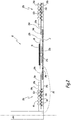
- the figure 1 has a device 10 in the rest configuration, that is to say that no vehicle is positioned on the device 10 to recharge its batteries.
- the device 10 comprises two supports 12a, 12b positioned on the ground S, a terminal 14 of configuration of the load of an electric vehicle, not shown in figures 1 and 2 , and a primary winding 16.
- the primary winding 16 is positioned on a housing 18 and connected to the mains, that is to say in this case to the terminal 14, by an electric cable 20.
- the housing 18 is positioned on slides 22a, 22b to which it is attached by fixing means 23a, 23b.
- the slides 22a, 22b are adapted to guide the movement of the housing 18.
- the housing 18 is positioned close to the ground S since the slides 22a and 22b are fixed to the ground S.
- the support 12a is more particularly described. However, the description of the support 12a also applies to the support 12b which is similar.
- the device 10 comprises, as illustrated in FIG. figure 1 , gearing systems such as two pulleys 24a, 24b each associated with a support 12a, 12b.
- the pulleys 24a, 24b are connected on the one hand, via a first cable 26a, 26b, to a different support 12a, 12b and on the other hand, to the housing 18 by means of a second cable noted respectively 28a, 28b.
- the pulleys 24a, 24b are able to multiply the movement of the first cable 26a, 26b on the second cable 28a, 28b by a factor, preferably equal to 16 and more generally between 4 and 20.
- the device 10 is generally symmetrical with respect to the housing 18.
- Each support 12a, 12b comprises a central portion 29a, 29b intended to receive wheels 30a and 30b of a vehicle 31, as shown in FIG. figure 3 .
- Each support 12a, 12b also comprises two ramps respectively noted 32a, 32b and 33a, 33b.
- the ramps 32a, 32b, 33a, 33b are intended to allow the vehicle 31 to rise on the central portion 29a, 29b and the descent of the vehicle 31 of the central portion 29a, 29b.
- the ramps 32a, 32b and 33a, 33b are inclined relative to the ground S so as to favor the raising and lowering of the vehicle 31.
- each support 12a, 12b comprises a first part 34a, 34b intended to be in contact with the wheels 30a, 30b and a second part 35a, 35b in contact with the ground S on which the device 10 rests.
- the supports 12a and 12b are receiving media wheels 30a, 30b and allow to fix the position of the vehicle 31 along a longitudinal axis X1 of the vehicle 31, also called first axis X1.
- the two supports 12a, 12b are positioned coaxially with respect to a transverse axis X2 of rotation of the wheels, also called second axis X2, and the two wheels 30a, 30b are arranged coaxially along the second axis X2 and are positioned on either side of the vehicle 31.
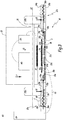
- the device 10 is shown in use configuration. That is to say that the vehicle 31, schematically represented by the two wheels 30a, 30b, a mechanical connection 36 between its two wheels 30a, 30b, a secondary winding 37, an electrical conversion device 38 and batteries 40, is in the recharging position of its batteries 40.
- the secondary winding 37 is electrically connected to the electrical conversion device 38 itself connected to the batteries 40.
- the secondary winding 37 is able to perform an inductive coupling with the primary winding 16.
- the primary winding 16 then acts as an emitter and the secondary winding 37 acts as a receiver.
- the conversion device 38 makes it possible to convert the induced current delivered by the secondary winding 37 into an acceptable current for recharging the batteries 40 which supply electricity to the vehicle 31.
- each support 12a, 12b comprises on its central portion 29a, 29b first elements 48 as visible on the Figures 2 to 5 .
- the first elements 48 project outwardly from the supports 12a, 12b, of the first portion 34a, 34b.
- the wheels 30a, 30b are sometimes, as visible in FIG. figure 3 , in contact with certain first elements 48.
- the first elements 48 in contact with the wheels 30a, 30b have been displaced relative to their visible rest position at figures 1 and 2 .
- the first elements 48 are able to move along a vertical axis X3, also called third axis X3, parallel to the weight P of the vehicle 31.
- the first elements 48 are positioned on the first portion 34a, 34b successively parallel to the second axis X2 and are in contact with the first cable 26a, 26b which crosses respectively the supports 12a, 12b parallel to the second axis X2.
- each support 12a, 12b comprises on its central portion 29a, 29b second elements 54 positioned on the second portion 35a, 35b, towards the first portion 34a, 34b.
- the second elements 54 are arranged successively parallel to the second axis X2 and are in contact with the first cable 26a, 26b.
- the first elements 48 and the second elements 54 are positioned relative to each other so that compared to the second elements 54, a first inner surface S1a, S1b of the first portion 34a, 34b is free while facing the first elements 48 a second inner surface S2a, S2b of the second portion 35a, 35b is free.
- first S1a, S1b and second S2a, S2b internal surfaces do not include over their entire length along the second axis X2 of the first elements 48 and second elements 54.
- first S1a, S1b and second S2a, S2b internal surfaces each comprise a portion without first elements 48 and second elements 54 on the side of the housing 18. Having a portion without first elements 48 and a portion without second elements 54 ensures the proper operation of the device 10.
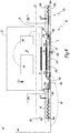
- the portion without first elements 48 ensures that depending on the position of the wheels 30a, 30b on the supports 12a, 12b, the number of first elements 48 moved, relative to their rest position, is not necessarily the same, as represented in figure 4 .
- the portions respectively without first elements 48 and without second elements 54 also allow, in the case where the two wheels 30a and 30b are completely included on the portion without first elements 48, not to stress the cables 26a, 26b, 28a, 28b, the first elements 48 and the second elements 54 and thus to limit the wear of the device 10.
- the first cable 26a, 26b of each support makes the connection between the first elements 48 specific to each support and the pulleys 24a, 24b.
- the first cable 26a, 26b is connected on one side to the pulley 24a, 24b and on the other to a fixed part 56a, 56b of each support 12a, 12b positioned after the first elements 48 and the second elements 54 relative to the case 18.
- the first elements 48 are adapted to apply a first force E1 on each first cable 26a, 26b towards the ground, parallel to the third axis X3, when they are set in motion because of the presence of a wheel 30a, 30b of the vehicle 31 on a central portion 29a, 29b of the support 12a, 12b to which they belong.
- the first elements 48 comprise a movable base 60 intended to be in contact with the wheels 30a, 30b and connected by a first shaft 62 to a first roller 64 in contact with the first cable 26a, 26b.
- Each first roller 64 is integral with the movement of the mobile base 60 associated with it and is adapted to exert the first force E1 corresponding to the weight P of the vehicle on the first cable 26a, 26b, when the base 60 with which it is associated is being moved by the wheel or wheels 30a, 30b of the vehicle 31.
- the second elements 54 comprise a fixed base 65 connected to a second roller 67.
- the second roller 67 is in contact with the first cable 26a, 26b.
- the second elements 54 are adapted to raise the first cable 26a, 26b relative to the ground S and the second portion 35a, 35b.
- the first force E1 applied to the first cable 26a, 26b, passing through the support 12a, 12b to which the first elements 48 belong generates a first displacement D1a, D1b of the first cable 26a, 26b, with respect to the pulley 24a, 24b, towards the support 12a, 12b.
- This first displacement D1a, D1b of the first cable 26a, 26b implies, thanks to the pulley 24a, 24b, a second displacement D2a, D2b multiplied the second cable 28a, 28b towards the support 12a, 12b.
- the second cable 28a, 28b is connected to the housing 18.
- the second cable 28a, 28b exerts a second force E2a, E2b, function of the first force E1, on the housing 18, parallel to the second axis X2, towards the support 12a , 12b comprising the first displaced elements 48.
- the pulleys 24a, 24b, first cables 26a, 26b and second cables are thus able to act on the position of the housing 18 relative to the secondary winding 37, along the second axis X2.
- the first effort E1 is applied in a direction parallel to the weight P of the vehicle 31, while the second force E2a, E2b is applied in a direction parallel to the second axis X2.
- the wheels 30a, 30b are respectively positioned at the same location on each support 12a, 12b.
- the second efforts E2a and E2b are therefore equal and the housing 18 remains positioned in the middle of the device 10.
- the positioning of the wheels 30a, 30b is different and the second efforts E2a and E2b are not equal.
- the housing 18 is offset from the center of the device along the second axis X2 and aligned with the secondary winding 37.
- the position of the housing 18 on the slide 22a has been modified with respect to the figure 3 so that the primary and secondary windings are aligned.
- the figure 6 shows the support 12a and corresponds to a first embodiment of the first elements 48, as well as the figure 5 .
- the support 12a comprises a frame 72 which passes through the support 12a parallel to the second axis X2.
- the frame 72 is hollowed in its center so that the first cable 26a can pass through the support 12a and that the first elements 48 and second elements 54 included in the support 12a can be installed.
- the frame 72 includes opposite each movable base 60 two stops 74, 76 adapted to limit the movement of each mobile base 60 towards the ground.
- Each movable base 60 is associated with two springs 78, 80 which connect it, along the third axis X3, to the frame 72.
- the springs 78, 80 are adapted to exert a third force E3 along the third axis X3 of the vehicle 31, in order to set the position of the first elements 48 when in the rest position, that is to say not in contact with the wheel 30a.
- the springs 78, 80 make it easier to return to the rest position of the first elements 48 when the vehicle 31 is moving down from the support 12a.
- the springs 78, 80 also make it possible to relieve in effort the first cable 26 a in contact with the first rollers 64.
- the second cable 28a, 28b preferably comprises a rigid portion 82 and an elastic portion 84, as illustrated in FIG. figure 1 .
- the rigid portion 82 is the link between the pulley 24a, 24b and the elastic portion 84
- the elastic portion 84 is the link between the rigid portion 82 and the housing 18.
- the elastic portion 84 allows to take into account the fact that There may be several wheel sizes 30a, 30b and several lengths, along the second axis X2, of mechanical connection 36 between the wheels 30a and 30b.
- the movable base 60 comprises a face 90 intended to be in contact with the wheel 30a, of rectangular shape. This face 90 is generally parallel to the ground S. Thus whatever the position of the wheel 30a on a first element 48 with which it is in contact, the first force E1 applied to this first element is generally the same.
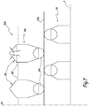
- a support 112a comprises first elements 148 visible to the figure 7 the first elements 148 are generally similar to those of the first embodiment and comprise a movable base 160 and a first roller 164 in contact with a first cable 126a.
- the movable base 160 includes a face 166 intended to be in contact with the triangular-shaped cylinder wheel 30a.
- the two faces of the triangular base cylinder, furthest from the first roller 164, along the axis X3, are inclined relative to the ground S by an angle ⁇ generally greater than 30 °. The value of the angle ⁇ depends on the dimensioning of the device 10.
- the first force E1 applied to the first element 148 is different depending on the position of the wheel 30a on a first element 148 with which it is in contact.
- This shape of the face 166 allows a finer adjustment of the alignment of the housing 18 and the secondary winding 37.
- a support 212a includes first members 248 including a movable base 260 and a roller 264 similarly to the first and second embodiments. Roller 264 is in contact with a first cable 226a.
- the movable base 260 comprises a third face 266 intended to be in contact with the wheel or wheels in the form of rectangle inclined at an angle ⁇ with respect to the ground S generally greater than 30 °.
- the value of the angle ⁇ depends on the overall dimensioning of the device 10. The inclination is such that the side 272 of the third highest face 266, with respect to the ground S, along the third axis X3, is the furthest of the case 18.
- each first element 248 comprises opposite the first element 248 closest towards the terminal 14, not shown in FIG. figure 8 , a notch 268.
- each first element 248 comprises an arm 270 which starts from its movable base 260 to the inside of the notch 268 of the mobile base 260 of the first element 248 closest towards the 18.
- each arm 270 is able to move the first elements 248 closer to the housing 18 than this first contact element in the same way.
- the third embodiment ensures the proper operation of the device 10 in the case of narrow wheels .
- the third embodiment in comparison with the first embodiment, there is a more linear operation of the device 10. More particularly, the movement of the first elements 248 depends on the contact surface between the face 266 and the wheel 30a.
- the device 10 operates regardless of the size of the wheels 30a, 30b and allows to position the primary winding 16 and the housing 18 relative to the secondary winding 37 as a function of the position of the wheels 30a and 30b along the second axis X2. Indeed a more or less large number of first elements 48, 148, 248 is moved according to the position of the wheels 30a, 30b. The position of the wheels 30a, 30b along the second axis X2 is recovered with a movement of the first elements 48, 148, 248 towards the ground and the weight P of the vehicle is used and converted into a displacement D2a, D2b parallel to the second axis X2 .
- the device 10 has a limited height. More specifically, the pulleys 24a, 24b make it possible to limit the measured height parallel to the third axis X3 of the supports 12a and 12b, to integrate the device 10 in a garage. Thus the size of the device 10 is minimal.
- the elastic portion of the second cable 28a, 28b makes it possible to limit the stresses in terms of force in the device 10.
- the elastic portion 84 offers a reliable and robust device 10.
- the invention makes it possible to have a positioning of the primary winding 16 with respect to the secondary winding 37 which is accurate and reliable, in order to have an efficient charging of the batteries 40 with an optimized efficiency.
- the positioning of the primary winding 16 relative to the secondary winding 37 is performed quickly, simply, inexpensively and automatically.
- the second cable 28a, 28b does not include two portions and is only a rigid cable.
- the width along the second axis X2 of the supports 12a, 12b is equal to two or three times the size of the wheels 30a, 30b.
- the gear reduction system used is not a pulley but a system of levers.
- the device comprises a single support or even more than two supports 12a, 12b.
- the displacement of the housing 18 will no longer be solely along the second axis X2.
- each support comprises only one first element 48 and only one second element 54.
- the primary winding is positioned in the housing.
- the first roller 64, 164, 264 is not in direct contact with the cable 26a, 26b, 126a, 226a, but is clean when the mobile base with which it is associated is set in motion to come exercise the first force E1 on the first cable 26a, 26b, 126a, 226a.
- the second roller 67 is not in contact with the cable 26a, 26b, 126a, 226a but is adapted to hold the cable 26a, 26b, 126a, 226a raised relative to the ground S and to the second part 35a.
- the first cable 26a, 126a, 226a, 26b passes through the support 12a, 12b only partially.
- first S1a, S1b and second S2a, S2b inner surfaces respectively comprise first elements 48 and second elements 54 over their entire length, along the second axis X2.
Landscapes
- Engineering & Computer Science (AREA)
- Power Engineering (AREA)
- Computer Networks & Wireless Communication (AREA)
- Transportation (AREA)
- Mechanical Engineering (AREA)
- Electric Propulsion And Braking For Vehicles (AREA)
Claims (14)
- Induktionsladevorrichtung (10) für Batterien (40) eines Elektroautomobils (31), wobei die Vorrichtung eine Primärwicklung (16) aufweist, die an eine elektrische Energiequelle (14) angeschlossen und in einem Gehäuse (18) eingeschlossen ist, wobei die Primärwicklung (16) in der Lage ist, eine induktive Kopplung mit einer Sekundärwicklung (37) herzustellen, die an die Batterien (40) des Fahrzeugs angeschlossen ist, und wobei das Gehäuse im Nahbereich des Bodens (S) positioniert ist, mindestens eine Aufnahmehalterung (12a, 12b, 112a, 212a) für mindestens ein Rad (30a, 30b) des Fahrzeugs umfassend, wobei jede Halterung auf dem Boden positioniert ist und mindestens ein erstes Element (48; 148; 248) aufweist, das in der Lage ist, wenn die Halterung (12a, 12b, 112a, 212a), zu der es gehört, in Kontakt mit dem Rad (30a, 30b) ist, sich in Richtung auf den Boden zu verlagern, wobei die Vorrichtung für jede Halterung Verbindungseinrichtungen (24a, 26a, 28a, 24b, 26b, 28b; 126a; 226a) zwischen jedem ersten Element (48; 148; 248) und dem beweglichen Gehäuse (18) aufweist, dadurch gekennzeichnet, dass die Verbindungseinrichtungen (24a, 26a, 28a, 24b, 26b, 28b; 1266a; 226a) in der Lage sind, in Abhängigkeit von der Verlagerung jedes ersten Elements, auf die Position entlang einer Drehungsquerachse (X2) der Räder (30a, 30b) des Gehäuses (18) in Bezug auf die Sekundärwicklung (37) einzuwirken.
- Vorrichtung nach Anspruch 1, dadurch gekennzeichnet, dass jede Halterung (12a, 12b) mehrere erste Elemente (48; 148; 248) aufweist, und dass für jede Halterung (12a, 12b, 112a, 212a) die ersten Elemente (48; 148; 248) von einem ersten Teil (34a, 34b), das dazu bestimmt ist, ein Rad oder Räder (30a, 30b) aufzunehmen, zum Außenbereich der Halterung (12a, 12b, 112a, 212a) hin vorstehen.
- Vorrichtung nach einem der vorhergehenden Ansprüche, dadurch gekennzeichnet, dass die Verbindungseinrichtungen (24a, 26a, 28a, 24b, 26b, 28b; 126a; 226a) für jede Halterung (12a, 12b, 112a, 212a) ein erstes Seil (26a, 26b; 126a; 226a), ein Bewegungsuntersetzungssystem (24a, 24b) und ein zweites Seil (28a, 28b) aufweisen, wobei das erste Seil (26a, 26b; 126a; 226a) mit dem Untersetzungssystem (24a, 24b) verbunden ist, und das Untersetzungssystem durch das zweite Seil (28a, 28b) mit dem Gehäuse (18) verbunden ist.
- Vorrichtung nach Anspruch 3, dadurch gekennzeichnet, dass das zweite Seil (28a, 28b) einen elastischen Teilbereich (84) aufweist.
- Vorrichtung nach einem der Ansprüche 3 oder 4, dadurch gekennzeichnet, dass jedes Untersetzungssystem (24a, 24b) ein Hebelsystem ist, das sich dazu eignet, die Verlagerung (D1a, D1b) des ersten Seils (26a, 26b; 126a; 226a) um einen Faktor zu untersetzen, der zwischen 4 und 20 beträgt.
- Vorrichtung nach einem der Ansprüche 3 bis 5, dadurch gekennzeichnet, dass sich für jede Halterung (12a, 12b, 112a, 212a) die ersten Elemente (48; 148; 248) dazu eignen, bei ihrer Verlagerung eine erste Kraft (E1) an jedes erste Seil (26a, 26b; 126a; 226a) anzulegen, wobei das erste Seil zumindest teilweise jede Halterung (12a, 12b, 112a, 212a) durchquert, und dass jede Halterung zweite Elemente (54) aufweist, die in der Lage sind, jedes erste Seil (26a, 26b; 126a; 226a) in Bezug auf den Boden angehoben zu halten.
- Vorrichtung nach Anspruch 6, dadurch gekennzeichnet, dass für jede Halterung (12a, 12b, 112a, 212a) das erste Seil (26a, 26b; 126a; 226a) auf einer Seite mit dem Untersetzungssystem (24a, 24b) und auf der anderen mit einem feststehenden Teil (56a, 56b) der Vorrichtung verbunden ist, und dass die erste Kraft (E1), die durch die ersten Elemente (48; 148; 248) bei deren Verlagerung angelegt wird, sich dazu eignet, eine Verlagerung (D1a, D1b) des ersten Seils (26a, 26b; 126a; 226a) in Bezug auf das Untersetzungssystem (24a, 24b) in Richtung auf die Halterung hervorzurufen, zu denen die ersten Elemente(48; 148; 248) gehören, wobei sich diese Verlagerung (D1a, D1b) dazu eignet, am zweiten Seil (28a, 28b) und folglich am Gehäuse (18) reproduziert und dabei durch das Untersetzungssystem (24a, 24b) untersetzt zu werden.
- Vorrichtung nach einem der Ansprüche 6 bis 7, dadurch gekennzeichnet, dass in jeder Halterung (12a, 12b, 112a, 212a) die ersten Elemente (48; 148; 248) jeweils eine entlang einer vertikalen Achse (X3) parallel zum Gewicht (P) des Fahrzeugs (31) beweglichen Sockel (60; 160; 260) aufweisen, der dazu bestimmt ist, mit dem Rad oder den Rädern (30a, 30b) in Kontakt zu stehen, wobei der bewegliche Sockel (60; 160; 260) fest mit einer ersten Rolle (64; 164; 264) verbunden ist, die in der Lage ist, die erste Kraft (E1) entlang der vertikalen Achse (X3) an das erste Seil (26a, 26b; 126a; 226a) anzulegen, und dass die zweiten Elemente (54) jeweils einen feststehenden Sockel (65) und eine zweite Rolle (67) haben, die in der Lage ist, das erste Seil in Bezug auf den Boden (S) angehoben zu halten.
- Vorrichtung nach Anspruch 8, dadurch gekennzeichnet, dass jede Halterung (12a) einen Unterbau (72) aufweist, der auf einer Fläche, die jedem mobilen Sockel (60; 160; 260) zugewandt ist, Anschläge (74, 76) hat, die dazu geeignet sind, die Verlagerung jedes mobilen Sockels (60; 160; 260) in Richtung auf den Boden (S) einzuschränken, und dass jeder mobile Sockel (60; 160; 260) mindestens einer Feder (78, 80) zugeordnet ist, die ihn mit dem Unterbau (72) verbindet, und die dazu geeignet ist, die Position der ersten Elemente (48; 148; 248) zu fixieren, wenn diese nicht mit dem Rad oder den Rädern (30a, 30b) in Kontakt sind.
- Vorrichtung nach einem der Ansprüche 8 bis 9, dadurch gekennzeichnet, dass jeder bewegliche Sockel (60) eine erste Fläche (90) in Form eines Rechtecks und insgesamt parallel zum Boden (S) aufweist, die dazu bestimmt ist, mit dem Rad oder den Rädern (30a, 30b) in Kontakt zu stehen.
- Vorrichtung nach einem der Ansprüche 8 bis 9, dadurch gekennzeichnet, dass jeder bewegliche Sockel (160) eine zweite Fläche (166) in Form eines Zylinders mit dreieckiger Basis aufweist, die dazu bestimmt ist, mit dem Rad oder den Rädern (30a, 30b) in Kontakt zu stehen.
- Vorrichtung nach einem der Ansprüche 8 bis 9, dadurch gekennzeichnet, dass jeder bewegliche Sockel (26) eine dritte Fläche (266) in Form eines in Bezug auf den Boden (S) geneigten Rechtecks aufweist, die dazu bestimmt ist, mit dem Rad oder den Rädern (30a, 30b) in Kontakt zu stehen, wobei eine entlang der vertikalen Achse (X3) höchste Seite (272) der dritten Fläche (266) diejenige ist, die vom Gehäuse (18) am weitesten entfernt ist, dass jedes erste Element (248) einen Arm (270) aufweist, der von seinem beweglichen Sockel (260) bis zum beweglichen Sockel (260) des naheliegendsten ersten Elements (248) ausgeht und dabei zum Gehäuse (18) hin verläuft, und dass das Rad oder die Räder in Kontakt mit einem ersten Kontaktelement (248) steht bzw. stehen und es verlagern, wobei der Arm (270) des ersten Kontaktelements dazu geeignet ist, alle anderen näher am Gehäuse (18) liegenden ersten Elemente auf dieselbe Weise zu verlagern wie das erste Kontaktelement.
- Vorrichtung nach einem der vorhergehenden Ansprüche, dadurch gekennzeichnet, dass die Vorrichtung zwei Halterungen (12a, 12b, 112a, 212a) aufweist, die beidseits des Gehäuses (18) angeordnet und dazu geeignet sind, jeweils ein Rad (30a, 30b) des Fahrzeugs (31) aufzunehmen, und dass jede Halterung (12a, 12b, 112a, 212a) dazu geeignet ist, die Position des Fahrzeugs entlang einer Längsachse (X1) des Fahrzeugs (31) zu fixieren.
- Vorrichtung nach Anspruch 13, dadurch gekennzeichnet, dass die zwei Halterungen (12a, 12b, 112a, 212a) koaxial entlang der Drehungsquerachse (X2) der Räder positioniert sind, und dass die Verbindungseinrichtungen (24a, 26a, 28a, 24b, 26b, 28b; 126a; 226a) in der Lage sind, entlang der Querachse (X2) auf die Position des Gehäuses (18) in Bezug auf die Sekundärwicklung (37) einzuwirken.
Applications Claiming Priority (1)
| Application Number | Priority Date | Filing Date | Title |
|---|---|---|---|
| FR1354320A FR3005612B1 (fr) | 2013-05-14 | 2013-05-14 | Dispositif de charge par induction de batteries d'un vehicule automobile electrique |
Publications (2)
| Publication Number | Publication Date |
|---|---|
| EP2803524A1 EP2803524A1 (de) | 2014-11-19 |
| EP2803524B1 true EP2803524B1 (de) | 2018-09-12 |
Family
ID=48795767
Family Applications (1)
| Application Number | Title | Priority Date | Filing Date |
|---|---|---|---|
| EP14168036.3A Active EP2803524B1 (de) | 2013-05-14 | 2014-05-13 | Induktionsaufladegerät für Batterie eines elektrischen Kraftfahrzeugs |
Country Status (2)
| Country | Link |
|---|---|
| EP (1) | EP2803524B1 (de) |
| FR (1) | FR3005612B1 (de) |
Families Citing this family (3)
| Publication number | Priority date | Publication date | Assignee | Title |
|---|---|---|---|---|
| FR3069813B1 (fr) * | 2017-08-01 | 2019-08-09 | Psa Automobiles Sa | Boitier mobile autonome a cable d’alimentation desenroule par ses rotations, pour recharger par induction une batterie de vehicule |
| CN107825976B (zh) * | 2017-10-26 | 2019-07-16 | 杭州电子科技大学 | 一种电动汽车无线充电装置及其充电方法 |
| CN111231741B (zh) * | 2020-01-23 | 2024-07-02 | 奥动新能源汽车科技有限公司 | 换电系统及包括其的换电站 |
Family Cites Families (6)
| Publication number | Priority date | Publication date | Assignee | Title |
|---|---|---|---|---|
| FR2740921A1 (fr) | 1995-11-06 | 1997-05-09 | Electricite De France | Dispositif automatise de charge des batteries d'un vehicule automobile a propulsion electrique |
| DE102007033654B4 (de) * | 2006-09-20 | 2019-08-01 | Sew-Eurodrive Gmbh & Co Kg | System mit Wagen und Basiseinheiten |
| US8466654B2 (en) | 2008-07-08 | 2013-06-18 | Qualcomm Incorporated | Wireless high power transfer under regulatory constraints |
| JP5525804B2 (ja) * | 2009-12-03 | 2014-06-18 | 現代自動車株式会社 | 一次コイル上昇型非接触充電装置 |
| CN102695629B (zh) * | 2010-01-05 | 2015-03-25 | 捷通国际有限公司 | 用于电动车辆的感应充电系统 |
| JPWO2012132145A1 (ja) * | 2011-03-30 | 2014-07-24 | 三洋電機株式会社 | 充電台 |
-
2013
- 2013-05-14 FR FR1354320A patent/FR3005612B1/fr not_active Expired - Fee Related
-
2014
- 2014-05-13 EP EP14168036.3A patent/EP2803524B1/de active Active
Non-Patent Citations (1)
| Title |
|---|
| None * |
Also Published As
| Publication number | Publication date |
|---|---|
| FR3005612A1 (fr) | 2014-11-21 |
| EP2803524A1 (de) | 2014-11-19 |
| FR3005612B1 (fr) | 2016-11-18 |
Similar Documents
| Publication | Publication Date | Title |
|---|---|---|
| EP3472919B1 (de) | Tragbare vorrichtung zur ausgabe eines stromkabels, insbesondere eines ladekabels für ein elektro- oder hybridfahrzeug | |
| FR3094151A3 (fr) | Systeme de recharge sans fil, station de recharge sans fil et vehicule | |
| EP3271983A1 (de) | Spule für stromkabel | |
| EP2421731A1 (de) | Vorrichtung zum bewegen und befestigen einer komponente zwischen zwei positionen | |
| FR3029862A1 (fr) | Determination d'une position de charge d'un dispositif de charge d'une borne de recharge | |
| FR2988455A1 (fr) | Dispositif de transmission de couple pour un vehicule automobile | |
| EP2803524A1 (de) | Induktionsaufladegerät für Batterie eines elektrischen Kraftfahrzeugs | |
| FR3072339A1 (fr) | Recharge par induction de vehicule electrique au moyen d’un robot | |
| FR3020427A1 (fr) | Dispositif de transmission de couple, notamment pour vehicule automobile | |
| FR3020426A1 (fr) | Dispositif de transmission de couple, notamment pour vehicule automobile | |
| EP4077033B1 (de) | Verfahren zum verbinden eines elektrischen ausgangs eines fahrzeugs mit einem steckverbinder aufweisend eine magnetisierungsoberfläche | |
| EP3660441A1 (de) | Ausklappvorrichtung eines ausklappbaren elements, insbesondere eines griffs, für ein waffensystem | |
| EP3842275B1 (de) | Elektrische energieaufnahmevorrichtung für ein fahrzeug, insbesondere ein schienenfahrzeug, und fahrzeug, insbesondere schienenfahrzeug, das eine solchen vorrichtung umfasst | |
| EP3530539A1 (de) | Stütz- und führungsvorrichtung eines zugseils eines fahrzeugs einer transportanlage, gelenk einer solchen vorrichtung und herstellungsverfahren dieser vorrichtung | |
| EP0559579B1 (de) | Vorrichtung zum Bewegen von Produktion im Inneren von Stapelbereichen eines automatisierten Lagers | |
| FR3100757A1 (fr) | Ensemble de recharge par induction de batteries de traction de vehicules electriques ou hybrides | |
| FR3108220A3 (fr) | Dispositif photovoltaïque mobile | |
| EP2628888A1 (de) | Elektromechanischer Rotationsantrieb für eine Last mit einem Momentenbegrenzer | |
| FR3142952A1 (fr) | Vehicule electrique comportant une connexion electrique pour la recharge. | |
| FR3142114A1 (fr) | Système de recharge d’un robot mobile | |
| WO2022254129A1 (fr) | Dispositif de connexion electrique par induction magnetique et procede de recharge electrique d'une batterie d'accumulateurs electriques d'un engin automobile | |
| EP0813951A1 (de) | Übertragungsring für Luftreifen oder für Luftreifengürtel | |
| FR3140654A1 (fr) | Ensemble de motorisation à effet gravitationnel | |
| WO2025162914A1 (fr) | Contacteur double tension | |
| WO2024094935A1 (fr) | Dispositif de chargement/déchargement de modules de batterie de véhicule |
Legal Events
| Date | Code | Title | Description |
|---|---|---|---|
| PUAI | Public reference made under article 153(3) epc to a published international application that has entered the european phase |
Free format text: ORIGINAL CODE: 0009012 |
|
| 17P | Request for examination filed |
Effective date: 20140513 |
|
| AK | Designated contracting states |
Kind code of ref document: A1 Designated state(s): AL AT BE BG CH CY CZ DE DK EE ES FI FR GB GR HR HU IE IS IT LI LT LU LV MC MK MT NL NO PL PT RO RS SE SI SK SM TR |
|
| AX | Request for extension of the european patent |
Extension state: BA ME |
|
| R17P | Request for examination filed (corrected) |
Effective date: 20150513 |
|
| RBV | Designated contracting states (corrected) |
Designated state(s): AL AT BE BG CH CY CZ DE DK EE ES FI FR GB GR HR HU IE IS IT LI LT LU LV MC MK MT NL NO PL PT RO RS SE SI SK SM TR |
|
| RIC1 | Information provided on ipc code assigned before grant |
Ipc: B60L 11/18 20060101AFI20180212BHEP |
|
| GRAP | Despatch of communication of intention to grant a patent |
Free format text: ORIGINAL CODE: EPIDOSNIGR1 |
|
| STAA | Information on the status of an ep patent application or granted ep patent |
Free format text: STATUS: GRANT OF PATENT IS INTENDED |
|
| INTG | Intention to grant announced |
Effective date: 20180412 |
|
| GRAS | Grant fee paid |
Free format text: ORIGINAL CODE: EPIDOSNIGR3 |
|
| GRAA | (expected) grant |
Free format text: ORIGINAL CODE: 0009210 |
|
| STAA | Information on the status of an ep patent application or granted ep patent |
Free format text: STATUS: THE PATENT HAS BEEN GRANTED |
|
| AK | Designated contracting states |
Kind code of ref document: B1 Designated state(s): AL AT BE BG CH CY CZ DE DK EE ES FI FR GB GR HR HU IE IS IT LI LT LU LV MC MK MT NL NO PL PT RO RS SE SI SK SM TR |
|
| REG | Reference to a national code |
Ref country code: GB Ref legal event code: FG4D Free format text: NOT ENGLISH |
|
| REG | Reference to a national code |
Ref country code: CH Ref legal event code: EP |
|
| REG | Reference to a national code |
Ref country code: IE Ref legal event code: FG4D Free format text: LANGUAGE OF EP DOCUMENT: FRENCH |
|
| REG | Reference to a national code |
Ref country code: AT Ref legal event code: REF Ref document number: 1040149 Country of ref document: AT Kind code of ref document: T Effective date: 20181015 |
|
| REG | Reference to a national code |
Ref country code: DE Ref legal event code: R096 Ref document number: 602014032138 Country of ref document: DE |
|
| REG | Reference to a national code |
Ref country code: NO Ref legal event code: T2 Effective date: 20180912 |
|
| REG | Reference to a national code |
Ref country code: NL Ref legal event code: MP Effective date: 20180912 |
|
| REG | Reference to a national code |
Ref country code: DE Ref legal event code: R079 Ref document number: 602014032138 Country of ref document: DE Free format text: PREVIOUS MAIN CLASS: B60L0011180000 Ipc: B60L0050500000 |
|
| REG | Reference to a national code |
Ref country code: LT Ref legal event code: MG4D |
|
| PG25 | Lapsed in a contracting state [announced via postgrant information from national office to epo] |
Ref country code: FI Free format text: LAPSE BECAUSE OF FAILURE TO SUBMIT A TRANSLATION OF THE DESCRIPTION OR TO PAY THE FEE WITHIN THE PRESCRIBED TIME-LIMIT Effective date: 20180912 Ref country code: LT Free format text: LAPSE BECAUSE OF FAILURE TO SUBMIT A TRANSLATION OF THE DESCRIPTION OR TO PAY THE FEE WITHIN THE PRESCRIBED TIME-LIMIT Effective date: 20180912 Ref country code: GR Free format text: LAPSE BECAUSE OF FAILURE TO SUBMIT A TRANSLATION OF THE DESCRIPTION OR TO PAY THE FEE WITHIN THE PRESCRIBED TIME-LIMIT Effective date: 20181213 Ref country code: BG Free format text: LAPSE BECAUSE OF FAILURE TO SUBMIT A TRANSLATION OF THE DESCRIPTION OR TO PAY THE FEE WITHIN THE PRESCRIBED TIME-LIMIT Effective date: 20181212 Ref country code: RS Free format text: LAPSE BECAUSE OF FAILURE TO SUBMIT A TRANSLATION OF THE DESCRIPTION OR TO PAY THE FEE WITHIN THE PRESCRIBED TIME-LIMIT Effective date: 20180912 Ref country code: SE Free format text: LAPSE BECAUSE OF FAILURE TO SUBMIT A TRANSLATION OF THE DESCRIPTION OR TO PAY THE FEE WITHIN THE PRESCRIBED TIME-LIMIT Effective date: 20180912 |
|
| PG25 | Lapsed in a contracting state [announced via postgrant information from national office to epo] |
Ref country code: AL Free format text: LAPSE BECAUSE OF FAILURE TO SUBMIT A TRANSLATION OF THE DESCRIPTION OR TO PAY THE FEE WITHIN THE PRESCRIBED TIME-LIMIT Effective date: 20180912 Ref country code: LV Free format text: LAPSE BECAUSE OF FAILURE TO SUBMIT A TRANSLATION OF THE DESCRIPTION OR TO PAY THE FEE WITHIN THE PRESCRIBED TIME-LIMIT Effective date: 20180912 Ref country code: HR Free format text: LAPSE BECAUSE OF FAILURE TO SUBMIT A TRANSLATION OF THE DESCRIPTION OR TO PAY THE FEE WITHIN THE PRESCRIBED TIME-LIMIT Effective date: 20180912 |
|
| REG | Reference to a national code |
Ref country code: AT Ref legal event code: MK05 Ref document number: 1040149 Country of ref document: AT Kind code of ref document: T Effective date: 20180912 |
|
| PG25 | Lapsed in a contracting state [announced via postgrant information from national office to epo] |
Ref country code: ES Free format text: LAPSE BECAUSE OF FAILURE TO SUBMIT A TRANSLATION OF THE DESCRIPTION OR TO PAY THE FEE WITHIN THE PRESCRIBED TIME-LIMIT Effective date: 20180912 Ref country code: IS Free format text: LAPSE BECAUSE OF FAILURE TO SUBMIT A TRANSLATION OF THE DESCRIPTION OR TO PAY THE FEE WITHIN THE PRESCRIBED TIME-LIMIT Effective date: 20190112 Ref country code: EE Free format text: LAPSE BECAUSE OF FAILURE TO SUBMIT A TRANSLATION OF THE DESCRIPTION OR TO PAY THE FEE WITHIN THE PRESCRIBED TIME-LIMIT Effective date: 20180912 Ref country code: PL Free format text: LAPSE BECAUSE OF FAILURE TO SUBMIT A TRANSLATION OF THE DESCRIPTION OR TO PAY THE FEE WITHIN THE PRESCRIBED TIME-LIMIT Effective date: 20180912 Ref country code: IT Free format text: LAPSE BECAUSE OF FAILURE TO SUBMIT A TRANSLATION OF THE DESCRIPTION OR TO PAY THE FEE WITHIN THE PRESCRIBED TIME-LIMIT Effective date: 20180912 Ref country code: CZ Free format text: LAPSE BECAUSE OF FAILURE TO SUBMIT A TRANSLATION OF THE DESCRIPTION OR TO PAY THE FEE WITHIN THE PRESCRIBED TIME-LIMIT Effective date: 20180912 Ref country code: NL Free format text: LAPSE BECAUSE OF FAILURE TO SUBMIT A TRANSLATION OF THE DESCRIPTION OR TO PAY THE FEE WITHIN THE PRESCRIBED TIME-LIMIT Effective date: 20180912 Ref country code: AT Free format text: LAPSE BECAUSE OF FAILURE TO SUBMIT A TRANSLATION OF THE DESCRIPTION OR TO PAY THE FEE WITHIN THE PRESCRIBED TIME-LIMIT Effective date: 20180912 Ref country code: RO Free format text: LAPSE BECAUSE OF FAILURE TO SUBMIT A TRANSLATION OF THE DESCRIPTION OR TO PAY THE FEE WITHIN THE PRESCRIBED TIME-LIMIT Effective date: 20180912 |
|
| PG25 | Lapsed in a contracting state [announced via postgrant information from national office to epo] |
Ref country code: SM Free format text: LAPSE BECAUSE OF FAILURE TO SUBMIT A TRANSLATION OF THE DESCRIPTION OR TO PAY THE FEE WITHIN THE PRESCRIBED TIME-LIMIT Effective date: 20180912 Ref country code: PT Free format text: LAPSE BECAUSE OF FAILURE TO SUBMIT A TRANSLATION OF THE DESCRIPTION OR TO PAY THE FEE WITHIN THE PRESCRIBED TIME-LIMIT Effective date: 20190112 Ref country code: SK Free format text: LAPSE BECAUSE OF FAILURE TO SUBMIT A TRANSLATION OF THE DESCRIPTION OR TO PAY THE FEE WITHIN THE PRESCRIBED TIME-LIMIT Effective date: 20180912 |
|
| REG | Reference to a national code |
Ref country code: DE Ref legal event code: R097 Ref document number: 602014032138 Country of ref document: DE |
|
| PLBE | No opposition filed within time limit |
Free format text: ORIGINAL CODE: 0009261 |
|
| STAA | Information on the status of an ep patent application or granted ep patent |
Free format text: STATUS: NO OPPOSITION FILED WITHIN TIME LIMIT |
|
| PG25 | Lapsed in a contracting state [announced via postgrant information from national office to epo] |
Ref country code: DK Free format text: LAPSE BECAUSE OF FAILURE TO SUBMIT A TRANSLATION OF THE DESCRIPTION OR TO PAY THE FEE WITHIN THE PRESCRIBED TIME-LIMIT Effective date: 20180912 |
|
| 26N | No opposition filed |
Effective date: 20190613 |
|
| PG25 | Lapsed in a contracting state [announced via postgrant information from national office to epo] |
Ref country code: SI Free format text: LAPSE BECAUSE OF FAILURE TO SUBMIT A TRANSLATION OF THE DESCRIPTION OR TO PAY THE FEE WITHIN THE PRESCRIBED TIME-LIMIT Effective date: 20180912 |
|
| REG | Reference to a national code |
Ref country code: CH Ref legal event code: PL |
|
| PG25 | Lapsed in a contracting state [announced via postgrant information from national office to epo] |
Ref country code: MC Free format text: LAPSE BECAUSE OF FAILURE TO SUBMIT A TRANSLATION OF THE DESCRIPTION OR TO PAY THE FEE WITHIN THE PRESCRIBED TIME-LIMIT Effective date: 20180912 Ref country code: CH Free format text: LAPSE BECAUSE OF NON-PAYMENT OF DUE FEES Effective date: 20190531 Ref country code: LI Free format text: LAPSE BECAUSE OF NON-PAYMENT OF DUE FEES Effective date: 20190531 |
|
| REG | Reference to a national code |
Ref country code: BE Ref legal event code: MM Effective date: 20190531 |
|
| PG25 | Lapsed in a contracting state [announced via postgrant information from national office to epo] |
Ref country code: LU Free format text: LAPSE BECAUSE OF NON-PAYMENT OF DUE FEES Effective date: 20190513 |
|
| PG25 | Lapsed in a contracting state [announced via postgrant information from national office to epo] |
Ref country code: TR Free format text: LAPSE BECAUSE OF FAILURE TO SUBMIT A TRANSLATION OF THE DESCRIPTION OR TO PAY THE FEE WITHIN THE PRESCRIBED TIME-LIMIT Effective date: 20180912 |
|
| PG25 | Lapsed in a contracting state [announced via postgrant information from national office to epo] |
Ref country code: IE Free format text: LAPSE BECAUSE OF NON-PAYMENT OF DUE FEES Effective date: 20190513 |
|
| PG25 | Lapsed in a contracting state [announced via postgrant information from national office to epo] |
Ref country code: BE Free format text: LAPSE BECAUSE OF NON-PAYMENT OF DUE FEES Effective date: 20190531 |
|
| PG25 | Lapsed in a contracting state [announced via postgrant information from national office to epo] |
Ref country code: CY Free format text: LAPSE BECAUSE OF FAILURE TO SUBMIT A TRANSLATION OF THE DESCRIPTION OR TO PAY THE FEE WITHIN THE PRESCRIBED TIME-LIMIT Effective date: 20180912 |
|
| PG25 | Lapsed in a contracting state [announced via postgrant information from national office to epo] |
Ref country code: MT Free format text: LAPSE BECAUSE OF FAILURE TO SUBMIT A TRANSLATION OF THE DESCRIPTION OR TO PAY THE FEE WITHIN THE PRESCRIBED TIME-LIMIT Effective date: 20180912 Ref country code: HU Free format text: LAPSE BECAUSE OF FAILURE TO SUBMIT A TRANSLATION OF THE DESCRIPTION OR TO PAY THE FEE WITHIN THE PRESCRIBED TIME-LIMIT; INVALID AB INITIO Effective date: 20140513 |
|
| PG25 | Lapsed in a contracting state [announced via postgrant information from national office to epo] |
Ref country code: MK Free format text: LAPSE BECAUSE OF FAILURE TO SUBMIT A TRANSLATION OF THE DESCRIPTION OR TO PAY THE FEE WITHIN THE PRESCRIBED TIME-LIMIT Effective date: 20180912 |
|
| PGFP | Annual fee paid to national office [announced via postgrant information from national office to epo] |
Ref country code: DE Payment date: 20250528 Year of fee payment: 12 |
|
| PGFP | Annual fee paid to national office [announced via postgrant information from national office to epo] |
Ref country code: GB Payment date: 20250526 Year of fee payment: 12 |
|
| PGFP | Annual fee paid to national office [announced via postgrant information from national office to epo] |
Ref country code: NO Payment date: 20250520 Year of fee payment: 12 |
|
| PGFP | Annual fee paid to national office [announced via postgrant information from national office to epo] |
Ref country code: FR Payment date: 20250526 Year of fee payment: 12 |