EP2803375A2 - Tragbare Infusionspumpe mit Kapazitätskupplungskommunikation und Energiesammlungseinrichtung - Google Patents
Tragbare Infusionspumpe mit Kapazitätskupplungskommunikation und Energiesammlungseinrichtung Download PDFInfo
- Publication number
- EP2803375A2 EP2803375A2 EP20140180178 EP14180178A EP2803375A2 EP 2803375 A2 EP2803375 A2 EP 2803375A2 EP 20140180178 EP20140180178 EP 20140180178 EP 14180178 A EP14180178 A EP 14180178A EP 2803375 A2 EP2803375 A2 EP 2803375A2
- Authority
- EP
- European Patent Office
- Prior art keywords
- user
- medical device
- power
- energy
- microcontroller
- Prior art date
- Legal status (The legal status is an assumption and is not a legal conclusion. Google has not performed a legal analysis and makes no representation as to the accuracy of the status listed.)
- Granted
Links
Images

Classifications
-
- A—HUMAN NECESSITIES
- A61—MEDICAL OR VETERINARY SCIENCE; HYGIENE
- A61M—DEVICES FOR INTRODUCING MEDIA INTO, OR ONTO, THE BODY; DEVICES FOR TRANSDUCING BODY MEDIA OR FOR TAKING MEDIA FROM THE BODY; DEVICES FOR PRODUCING OR ENDING SLEEP OR STUPOR
- A61M5/00—Devices for bringing media into the body in a subcutaneous, intra-vascular or intramuscular way; Accessories therefor, e.g. filling or cleaning devices, arm rests
- A61M5/14—Infusion devices, e.g. infusing by gravity; Blood infusion; Accessories therefor
- A61M5/142—Pressure infusion, e.g. using pumps
- A61M5/14244—Pressure infusion, e.g. using pumps adapted to be carried by the patient, e.g. portable on the body
- A61M5/14248—Pressure infusion, e.g. using pumps adapted to be carried by the patient, e.g. portable on the body of the skin patch type
-
- A—HUMAN NECESSITIES
- A61—MEDICAL OR VETERINARY SCIENCE; HYGIENE
- A61M—DEVICES FOR INTRODUCING MEDIA INTO, OR ONTO, THE BODY; DEVICES FOR TRANSDUCING BODY MEDIA OR FOR TAKING MEDIA FROM THE BODY; DEVICES FOR PRODUCING OR ENDING SLEEP OR STUPOR
- A61M5/00—Devices for bringing media into the body in a subcutaneous, intra-vascular or intramuscular way; Accessories therefor, e.g. filling or cleaning devices, arm rests
- A61M5/14—Infusion devices, e.g. infusing by gravity; Blood infusion; Accessories therefor
- A61M5/168—Means for controlling media flow to the body or for metering media to the body, e.g. drip meters, counters
- A61M5/172—Means for controlling media flow to the body or for metering media to the body, e.g. drip meters, counters electrical or electronic
- A61M5/1723—Means for controlling media flow to the body or for metering media to the body, e.g. drip meters, counters electrical or electronic using feedback of body parameters, e.g. blood sugar or pressure
-
- H—ELECTRICITY
- H04—ELECTRIC COMMUNICATION TECHNIQUE
- H04B—TRANSMISSION
- H04B13/00—Transmission systems characterised by the medium used for transmission, not provided for in groups H04B3/00 - H04B11/00
- H04B13/005—Transmission systems in which the medium consists of the human body
-
- A—HUMAN NECESSITIES
- A61—MEDICAL OR VETERINARY SCIENCE; HYGIENE
- A61B—DIAGNOSIS; SURGERY; IDENTIFICATION
- A61B2560/00—Constructional details of operational features of apparatus; Accessories for medical measuring apparatus
- A61B2560/02—Operational features
- A61B2560/0204—Operational features of power management
- A61B2560/0214—Operational features of power management of power generation or supply
-
- A—HUMAN NECESSITIES
- A61—MEDICAL OR VETERINARY SCIENCE; HYGIENE
- A61B—DIAGNOSIS; SURGERY; IDENTIFICATION
- A61B5/00—Measuring for diagnostic purposes; Identification of persons
- A61B5/0002—Remote monitoring of patients using telemetry, e.g. transmission of vital signals via a communication network
- A61B5/0031—Implanted circuitry
-
- A—HUMAN NECESSITIES
- A61—MEDICAL OR VETERINARY SCIENCE; HYGIENE
- A61B—DIAGNOSIS; SURGERY; IDENTIFICATION
- A61B5/00—Measuring for diagnostic purposes; Identification of persons
- A61B5/145—Measuring characteristics of blood in vivo, e.g. gas concentration or pH-value ; Measuring characteristics of body fluids or tissues, e.g. interstitial fluid or cerebral tissue
- A61B5/14532—Measuring characteristics of blood in vivo, e.g. gas concentration or pH-value ; Measuring characteristics of body fluids or tissues, e.g. interstitial fluid or cerebral tissue for measuring glucose, e.g. by tissue impedance measurement
-
- A—HUMAN NECESSITIES
- A61—MEDICAL OR VETERINARY SCIENCE; HYGIENE
- A61M—DEVICES FOR INTRODUCING MEDIA INTO, OR ONTO, THE BODY; DEVICES FOR TRANSDUCING BODY MEDIA OR FOR TAKING MEDIA FROM THE BODY; DEVICES FOR PRODUCING OR ENDING SLEEP OR STUPOR
- A61M2205/00—General characteristics of the apparatus
- A61M2205/35—Communication
- A61M2205/3507—Communication with implanted devices, e.g. external control
- A61M2205/3538—Communication with implanted devices, e.g. external control using electrical conduction through the body of the patient
-
- A—HUMAN NECESSITIES
- A61—MEDICAL OR VETERINARY SCIENCE; HYGIENE
- A61M—DEVICES FOR INTRODUCING MEDIA INTO, OR ONTO, THE BODY; DEVICES FOR TRANSDUCING BODY MEDIA OR FOR TAKING MEDIA FROM THE BODY; DEVICES FOR PRODUCING OR ENDING SLEEP OR STUPOR
- A61M2205/00—General characteristics of the apparatus
- A61M2205/35—Communication
- A61M2205/3546—Range
- A61M2205/3553—Range remote, e.g. between patient's home and doctor's office
-
- A—HUMAN NECESSITIES
- A61—MEDICAL OR VETERINARY SCIENCE; HYGIENE
- A61M—DEVICES FOR INTRODUCING MEDIA INTO, OR ONTO, THE BODY; DEVICES FOR TRANSDUCING BODY MEDIA OR FOR TAKING MEDIA FROM THE BODY; DEVICES FOR PRODUCING OR ENDING SLEEP OR STUPOR
- A61M2205/00—General characteristics of the apparatus
- A61M2205/35—Communication
- A61M2205/3546—Range
- A61M2205/3561—Range local, e.g. within room or hospital
-
- A—HUMAN NECESSITIES
- A61—MEDICAL OR VETERINARY SCIENCE; HYGIENE
- A61M—DEVICES FOR INTRODUCING MEDIA INTO, OR ONTO, THE BODY; DEVICES FOR TRANSDUCING BODY MEDIA OR FOR TAKING MEDIA FROM THE BODY; DEVICES FOR PRODUCING OR ENDING SLEEP OR STUPOR
- A61M2205/00—General characteristics of the apparatus
- A61M2205/35—Communication
- A61M2205/3546—Range
- A61M2205/3569—Range sublocal, e.g. between console and disposable
-
- A—HUMAN NECESSITIES
- A61—MEDICAL OR VETERINARY SCIENCE; HYGIENE
- A61M—DEVICES FOR INTRODUCING MEDIA INTO, OR ONTO, THE BODY; DEVICES FOR TRANSDUCING BODY MEDIA OR FOR TAKING MEDIA FROM THE BODY; DEVICES FOR PRODUCING OR ENDING SLEEP OR STUPOR
- A61M2205/00—General characteristics of the apparatus
- A61M2205/35—Communication
- A61M2205/3576—Communication with non implanted data transmission devices, e.g. using external transmitter or receiver
- A61M2205/3584—Communication with non implanted data transmission devices, e.g. using external transmitter or receiver using modem, internet or Bluetooth®
-
- A—HUMAN NECESSITIES
- A61—MEDICAL OR VETERINARY SCIENCE; HYGIENE
- A61M—DEVICES FOR INTRODUCING MEDIA INTO, OR ONTO, THE BODY; DEVICES FOR TRANSDUCING BODY MEDIA OR FOR TAKING MEDIA FROM THE BODY; DEVICES FOR PRODUCING OR ENDING SLEEP OR STUPOR
- A61M2205/00—General characteristics of the apparatus
- A61M2205/35—Communication
- A61M2205/3576—Communication with non implanted data transmission devices, e.g. using external transmitter or receiver
- A61M2205/3592—Communication with non implanted data transmission devices, e.g. using external transmitter or receiver using telemetric means, e.g. radio or optical transmission
-
- A—HUMAN NECESSITIES
- A61—MEDICAL OR VETERINARY SCIENCE; HYGIENE
- A61M—DEVICES FOR INTRODUCING MEDIA INTO, OR ONTO, THE BODY; DEVICES FOR TRANSDUCING BODY MEDIA OR FOR TAKING MEDIA FROM THE BODY; DEVICES FOR PRODUCING OR ENDING SLEEP OR STUPOR
- A61M2205/00—General characteristics of the apparatus
- A61M2205/50—General characteristics of the apparatus with microprocessors or computers
- A61M2205/52—General characteristics of the apparatus with microprocessors or computers with memories providing a history of measured variating parameters of apparatus or patient
-
- A—HUMAN NECESSITIES
- A61—MEDICAL OR VETERINARY SCIENCE; HYGIENE
- A61M—DEVICES FOR INTRODUCING MEDIA INTO, OR ONTO, THE BODY; DEVICES FOR TRANSDUCING BODY MEDIA OR FOR TAKING MEDIA FROM THE BODY; DEVICES FOR PRODUCING OR ENDING SLEEP OR STUPOR
- A61M2205/00—General characteristics of the apparatus
- A61M2205/82—Internal energy supply devices
- A61M2205/8206—Internal energy supply devices battery-operated
- A61M2205/8212—Internal energy supply devices battery-operated with means or measures taken for minimising energy consumption
-
- A—HUMAN NECESSITIES
- A61—MEDICAL OR VETERINARY SCIENCE; HYGIENE
- A61M—DEVICES FOR INTRODUCING MEDIA INTO, OR ONTO, THE BODY; DEVICES FOR TRANSDUCING BODY MEDIA OR FOR TAKING MEDIA FROM THE BODY; DEVICES FOR PRODUCING OR ENDING SLEEP OR STUPOR
- A61M2205/00—General characteristics of the apparatus
- A61M2205/82—Internal energy supply devices
- A61M2205/8237—Charging means
- A61M2205/8243—Charging means by induction
-
- A—HUMAN NECESSITIES
- A61—MEDICAL OR VETERINARY SCIENCE; HYGIENE
- A61M—DEVICES FOR INTRODUCING MEDIA INTO, OR ONTO, THE BODY; DEVICES FOR TRANSDUCING BODY MEDIA OR FOR TAKING MEDIA FROM THE BODY; DEVICES FOR PRODUCING OR ENDING SLEEP OR STUPOR
- A61M2205/00—General characteristics of the apparatus
- A61M2205/82—Internal energy supply devices
- A61M2205/8237—Charging means
- A61M2205/825—Charging means using mechanical generation of electricity, e.g. hand cranked generators
-
- A—HUMAN NECESSITIES
- A61—MEDICAL OR VETERINARY SCIENCE; HYGIENE
- A61M—DEVICES FOR INTRODUCING MEDIA INTO, OR ONTO, THE BODY; DEVICES FOR TRANSDUCING BODY MEDIA OR FOR TAKING MEDIA FROM THE BODY; DEVICES FOR PRODUCING OR ENDING SLEEP OR STUPOR
- A61M2205/00—General characteristics of the apparatus
- A61M2205/82—Internal energy supply devices
- A61M2205/8237—Charging means
- A61M2205/8256—Charging means being integrated in the case or housing of the apparatus
-
- A—HUMAN NECESSITIES
- A61—MEDICAL OR VETERINARY SCIENCE; HYGIENE
- A61M—DEVICES FOR INTRODUCING MEDIA INTO, OR ONTO, THE BODY; DEVICES FOR TRANSDUCING BODY MEDIA OR FOR TAKING MEDIA FROM THE BODY; DEVICES FOR PRODUCING OR ENDING SLEEP OR STUPOR
- A61M2209/00—Ancillary equipment
- A61M2209/01—Remote controllers for specific apparatus
-
- A—HUMAN NECESSITIES
- A61—MEDICAL OR VETERINARY SCIENCE; HYGIENE
- A61M—DEVICES FOR INTRODUCING MEDIA INTO, OR ONTO, THE BODY; DEVICES FOR TRANSDUCING BODY MEDIA OR FOR TAKING MEDIA FROM THE BODY; DEVICES FOR PRODUCING OR ENDING SLEEP OR STUPOR
- A61M2230/00—Measuring parameters of the user
- A61M2230/20—Blood composition characteristics
- A61M2230/201—Glucose concentration
-
- A—HUMAN NECESSITIES
- A61—MEDICAL OR VETERINARY SCIENCE; HYGIENE
- A61M—DEVICES FOR INTRODUCING MEDIA INTO, OR ONTO, THE BODY; DEVICES FOR TRANSDUCING BODY MEDIA OR FOR TAKING MEDIA FROM THE BODY; DEVICES FOR PRODUCING OR ENDING SLEEP OR STUPOR
- A61M2230/00—Measuring parameters of the user
- A61M2230/63—Motion, e.g. physical activity
Definitions
- the present invention relates generally to wearable, self-contained drug infusion devices that take advantage of the wearable nature of such devices to provide lower cost power components and communication components with lower power requirements and enhanced security as compared to wireless communication schemes.
- Diabetes is a group of diseases marked by high levels of blood glucose resulting from defects in insulin production, insulin action, or both. There are 23.6 million people in the United States, or 8% of the population, who have diabetes. The total prevalence of diabetes has increased 13.5% since the 2005-2007 time period. Diabetes can lead to serious complications and premature death, but there are well-known products available for people with diabetes to help control the disease and lower the risk of complications.
- Treatment options for people with diabetes include specialized diets, oral medications and/or insulin therapy.
- the primary goal for diabetes treatment is to control the patient's blood glucose (sugar) level in order to increase the chances of a complication-free life. It is not always easy, however, to achieve good diabetes management, while balancing other life demands and circumstances.
- the first mode includes syringes and insulin pens that require a needle stick at each injection, typically three to four times per day, but are simple to use and relatively low in cost.
- Another widely adopted and effective method of treatment for managing diabetes is the use of a conventional insulin pump.
- Insulin pumps can help the user keep their blood glucose levels within target ranges based on their individual needs, by continuous infusion of insulin. By using an insulin pump, the user can match their insulin therapy to their lifestyle, rather than matching their lifestyle to how an insulin injection, for example, is working for them.
- Conventional insulin pumps are capable of delivering rapid or short-acting insulin 24 hours a day through a catheter placed under the skin. Insulin doses are typically administered at a basal rate and in a bolus dose. Basal insulin is delivered continuously over 24 hours, and strives to keep one's blood glucose levels in a consistent range between meals and overnight. Some insulin pumps are capable of programming the basal rate of insulin to vary according to the different times of the day and night. Bolus doses are typically administered when the user takes a meal, and generally provide a single additional insulin injection to balance the carbohydrates consumed. Some conventional insulin pumps enable the user to program the volume of the bolus dose in accordance with the size or type of the meal consumed. Conventional insulin pumps also enable a user to take in a correctional or supplemental bolus of insulin to better control their blood glucose level to within their target range.
- Insulin pumps deliver insulin over time rather than in single injections and thus typically result in fewer large swings in one's blood glucose levels.
- Conventional insulin pumps reduce the number of needle sticks which the patient must endure, and make diabetes management easier and more effective for the user, thus considerably enhancing the quality of the user's life.
- Insulin pumps however can be cumbersome to use and are typically more expensive than other methods of treatment. From a lifestyle standpoint, the conventional pump, tubing, and injection set are inconvenient and bothersome for the user.
- New advances in insulin therapy provide "wearable" drug infusion devices that are lower in cost and more convenient and comfortable to use than conventional insulin pumps. Some of these devices are intended to be partially or entirely disposable, and in theory provide many of the advantages of conventional insulin pumps without the initial high cost and inconvenience of conventional insulin pumps.
- Wearable medical devices capable of performing similar functions as conventional insulin pumps are becoming increasingly more prevalent, but are still high in cost. Such medical devices are typically disposed of after a maximum of 3 days in operation. Driving factors for the duration of use for such medical devices include the viability of the injection site for a prolonged period and the limitations of the power supply in providing the necessary power over this period. Since common wearable medical devices are typically used for such short durations, it is necessary that the unit cost of each medical device be affordably low.
- typical wearable devices are required to communicate with a host device such as a Blood Glucose Monitor or a Personal Diabetes Monitor. Available wearable devices typically communicate with the host device using well-known wireless technology such as Bluetooth® or ZigBee®.
- Wireless communication technologies provide effective communication between the wearable device and a host device.
- the components necessary for realizing these technologies are relatively expensive, especially in an application using a disposable medical device.
- wireless communication technology components drive up the cost for providing the device, but they also consume sufficient power to shorten the life of the medical device, further driving up cost.
- one major constraint of common wearable medical devices is the high cost of providing a reliable power supply for powering the necessary components to realize an effective and fully functional medical device. Further, there must be a balance in realizing a fully functional, affordable medical device and providing the medical device in a package that is convenient, comfortable and discreet for the user.
- Typical medical devices use a battery or battery array for providing power to the medical device. Such standard arrangements, however, unnecessarily drive up the cost of each medical device and can be bulky and relatively heavy. Further, the standard battery or battery array is usually disposed of at the same time as that of the used wearable medical device, thus contributing to unnecessary waste. Not until the cost of such medical devices is significantly reduced, will wearable medical devices be a viable option for many users.
- Exemplary embodiments of the present invention address at least the above problems and/or disadvantages and provide at least the advantages described below. Accordingly, it is an object of exemplary embodiments of the present invention to provide lower power system components and an alternative energy source for powering the medical device that are lower in cost and capable of providing improved functionality and extended life of the wearable medical device. It is a further object of exemplary embodiments of the present invention to provide a device capable of communicating with a host controller and/or body sensor without the added component cost and power drain associated with wireless transceivers while also providing greater security over that of wireless transceivers.
- a wearable medical device in contact with a user's body for administering drug therapy to the user, the medical device comprising a microcontroller electrically coupled to a pump mechanism, a transceiver and a power supply system.
- the microcontroller commands the pump mechanism to administer a drug to the user.
- the transceiver communicates with a host device on or near the user's body via a personal area network (PAN) that transmits data across the user's body, wherein said host device monitors or controls the medical device.
- PAN personal area network
- the power supply system selectively provides power to the microcontroller, pump mechanism and transceiver supplied from an energy harvesting component that harvests energy from the user's body.
- the personal area network transceiver communicates to the host device via an electric field generated on the user's skin at a contact site of the medical device on the user's body.
- the energy harvesting component stores energy realized by a thermal difference between the user's body and an external environment when the medical device contacts the user's body.
- the energy harvesting component may also store energy generated by the user's movement when the medical device is positioned on the user's body.
- the energy harvesting component provides at least a portion of the medical device's energy requirement.
- the medical device may further comprise an additional power source for providing at least a portion of power to the pump mechanism when actively administering a drug to the user in an active mode, wherein said energy harvesting component powers the medical device when in a lower power state such as a standby mode.
- the transceiver further communicates with a sensor implantable in the user's body, or in otherwise continuous contact with the user's body, via the personal area network.
- An embodiment also comprises a sensor electrically coupled to the microcontroller which is an ultra-low power microcontroller.
- a medical device in contact with a user's body for administering drug therapy to the user.
- the medical device comprises a housing in contact with a user's body.
- the housing further contains a microcontroller controlling a pump mechanism to deliver a drug at a contact site on the user's body.
- a power supply system comprising an energy harvesting component to harvest energy from the user's body is also provided.
- a harvested energy storage unit stores the harvested energy, and a power distribution unit selectively provides the stored energy to the microcontroller and the pump mechanism.
- the power distribution unit preferably provides a first power to the microcontroller when in an active mode, and supplies a second, lower power to the microcontroller in a standby mode of the medical device.
- the harvested energy storage unit provides at least a portion of the second power and the power supply system further comprises a battery to supply at least a portion of the first power.
- the housing may further contain a transceiver to communicate with a host monitoring device and a sensor in contact with the user's body via a personal area network that transmits data across the user's body.
- a third aspect of the present invention provides a wearable medical device system for providing drug therapy to a user.
- the system comprises a wearable medical device provided in contact with the user's skin, said medical device comprising a pump mechanism for administering a prescribed volume of a liquid drug to the user.
- a bodily function sensor is provided in continuous contact with the user's body, and further in communication with the wearable medical device.
- the wearable medical device further comprises a microcontroller to control the prescribed volume of the drug according to physiological data received from the sensor, wherein the wearable patch pump and the sensor are at least partially powered by energy harvested from the user's body.
- the sensor may be contained in the wearable patch pump or when implanted in the user's body, the sensor communicates with the wearable patch pump via a personal area network that uses the user's body as a transmission medium to transmit the physiological data.
- the method provides a microcontroller electrically coupled to a pump mechanism, a transceiver and a power supply system.
- the method configures the microcontroller to command the pump mechanism to administer a drug to the user and harvests energy from the user's body.
- the method configures the power supply system to selectively provide the harvested energy to the microcontroller, pump mechanism and transceiver and communicates with a host device on or near the user's body via a personal area network that transmits data across the user's body via the transceiver, wherein said host device monitors or controls the medical device and transmits data for at least controlling the administering of the drug to the user. Additionally, the method receives at the medical device said data transmitted via the personal area network from the host device and controls the pump mechanism to administer the drug to the user.
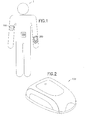
- Medical device 100 may be used for the delivery of medication, preferably but not necessarily insulin, by continuous infusion into or through the skin of a patient.
- the medication may be provided in liquid, gel or even solid form in some embodiments.
- the device 100 is intended to be worn on the surface of the skin by the user, with a cannula (hollow needle) penetrating into the user's skin or transcutaneously through the user's skin into the subcutaneous tissue.
- Device 100 may also provide intradermal, intramuscular and intravenous drug infusion.
- device 100 may be pre-programmable and comprise basic functionality for users requiring less control.
- Other specific functions, features and characteristics of the wearable medical device in accordance with the present invention can be found in commonly-assigned U.S. Pat. No. 6,589,229 issued to Robert I Connelly, et al.
- exemplary embodiments of the present invention preferably include a host device 200 in communication with medical device 100.
- Host device 200 can be embodied as a Blood Glucose Monitor (BGM), a Personal Diabetes Monitor (PDM), a PDA, a smartphone, or any other handheld or wearable, lightweight computing device.
- host device 200 comprises a notebook computer or any other computing device capable of communicating with medical device 100.
- host device 200 and medical device 100 are preferably configured to communicate via additional networks to other external devices for transmitting patient data or other records to a healthcare provider, for instance. This method of communication is not required to be the same as the method used for communicating between the host device 200 and medical device 100.
- Host device 200 is capable of providing system intelligence for the medical device 100.
- Host device 200 can be configured to process data received from medical device 100 and communicate to the medical device 100 instructions for any necessary adjustments to the user's infusion rate by adjusting the user's basal rate or modifying a bolus dose.
- Host device 200 is preferably capable of determining and controlling an injection/infusion rate of a bolus and the duration of the bolus injection/infusion for providing optimum therapeutic benefit for the user. Further, host device 200 may be capable of providing an alarm to alert the user that their insulin level approached or crossed an upper or lower insulin threshold or when a user's blood glucose level trend is violated.
- host device 200 is capable of storing data related to a user's infusion rate and schedule history and can be configured to analyze such data for providing useful trends or statistics to realize a more precise infusion rate for the user. Host device 200 may also be configured to receive system diagnostic information from medical device 100 and alert the user if the medical device 100 is not operating properly.
- medical device 100 may also be configured to be fully functional so that all of the functions described above with respect to host device 200 can be incorporated therein.
- medical device 100 can further comprise a storage component for storing the infusion rate and schedule information of a user to be uploaded at an optional host device 200, or any other external device, via a personal area network or other communication technique at the user's convenience.
- Medical device 100 may also optionally comprise necessary components for measuring or sensing the blood glucose levels of a patient and making necessary adjustments to the user's infusion rate, and providing an alarm or alert to the user comprising abnormal insulin levels or system diagnostic information.
- Medical device 100 comprises at least a pump mechanism 102, a microcontroller unit 104, a transceiver system 106 and a power supply system 108.
- Pump mechanism 102 can be any known mechanism for providing a medicament or drug into or through the user's skin. Pump mechanism 102 minimally provides at least a reservoir or other unit for housing a liquid medicament, a cannula for infusing the medicament into the user, and a pump for actuating the liquid medicament through the cannula. Exemplary embodiments of pump mechanism 102 suitable for use in the present invention can be found in commonly-assigned U.S. Pat. No.
- pump mechanism 102 be compact, lightweight, accurate and require low power for effective operation.
- Microcontroller 104 in the first embodiment of the present invention is provided at least for controlling pump mechanism 102.
- Microcontroller 104 is preferably an ultra low-power (ULP) programmable controller, ideally operating in a range up to 3.6 V, which combines the necessary processing power and peripheral set to control drug delivery through the pump mechanism 102, monitor an optional sensor 300, and control any communication requirements for communicating with the host device 200.
- the first exemplary embodiment of the present invention provides a "smart" medical device that is capable of communicating with host device 200 via transceiver system 106.
- Microcontroller 104 is preferably fully programmable by the host device to precisely control the user's basal infusion rate and necessary bolus injections.
- host device 200 can control microcontroller 104 to activate pump mechanism 102, perform system diagnostics, monitor system parameters of medical device 100 and record infusion data and other information communicated from medical device 100.
- Microcontroller 104 in the first embodiment is preferably embodied in a "system on a chip” (SoC) including the circuitry for the transceiver system 106. SoC designs usually consume less power and have a lower cost and higher reliability than the multi-chip systems that they replace. By providing a single chip system, assembly costs may be reduced as well.
- SoC system on a chip
- Transceiver system 106 is compatible with the transceiver at the host device 200 and any other peripheral units such as optional bodily function sensor 300 in order to communicate with each device.
- transceiver system 106 is provided for communicating at least system diagnostic data, infusion rate or infusion schedule information to host device 200 or some other external device. Additionally, transceiver system 106 receives commands and data from host device 200 enabling the programming of microcontroller 104 and control of other system functions of medical device 100. Diagnostic data can refer to any information about the functionality of the medical device and its system components, such as whether the cannula is blocked or otherwise rendered unusable, the remaining volume of liquid medicament available, and the remaining power available for controlling the medical device 100.
- RF wireless communications such as Bluetooth®, Zigbee®, 802.11, or other conventional solutions. Some medical devices even communicate with the host device via a line-of-sight using infrared (IR) technology. Wireless communication systems, since they do not require a line of sight, are preferred over IR technology. Conventional wireless technology, however, is a driving contributor in the prohibitive cost of medical devices that use their respective technologies. Conventional wireless systems require an RF transceiver and antenna to operate.
- PAN personal area network
- a personal area network in the exemplary embodiments, can be created with simple, low-cost microcontrollers and analog components, requires less power to operate than RF systems and are at least as secure as RF systems.
- the use of a personal area network in the exemplary embodiments reduces the overall cost for device/host communications and enables extended use duration due to the reduced component cost and lower power requirements.
- an exemplary PAN transceiver system 106 is preferably packaged in a SoC design with microcontroller 104 for further minimizing the overall cost of medical device 100.
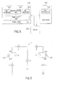
- PAN transceiver 106 preferably establishes a personal area network to communicate with host device 200 via a "near field" electric field that transmits data using the human body as a transport medium. Medical device 100 and host device 200 each need PAN transceivers 106 and 206, respectively, in order to communicate to each other through the body.
- a transmitter electrode 402, facing the body at transceiver 106, and the user's skin act as a capacitor A.
- the user's skin and a receiver electrode 404, at transceiver 206 act as a capacitor B.
- FIG. 4 a transmitter electrode 402 facing the body at transceiver 106, and the user's skin act as a capacitor A.
- the user's skin and a receiver electrode 404, at transceiver 206 act as a capacitor B.
- PAN transceiver 106 acting as a transmitter, is capacitively coupled to PAN transceiver 206, acting as a receiver.
- PAN transceiver 206 may act as the transmitter with PAN transceiver 106 being the receiver.
- the human body acts as a conductor capable of carrying a current through the body from transceiver 106 to transceiver 206.
- Earth ground includes any conductors and dielectrics in the environment in close proximity to the user's body, and acts as a return path.
- Electrode 406 at transceiver 106 and "earth ground” act as a capacitor C
- electrode 408 at transceiver 206 and “earth ground” act as a capacitor D
- “earth ground” needs to be electrically isolated from the human body in order to prevent shorting of the communication circuit, thus effectively acting as capacitor G.
- FIG. 5 illustrates an electric circuit model of a personal area network in an exemplary embodiment of the present invention. Because electrode 402 has a lower impedance to the user's body than electrode 406, the transmitter is enabled to provide an oscillating potential on electrode 406. The oscillating potential results in a displacement current that is real and is transferred to the human body. Transceiver 106 can effectively modulate the displacement current to transmit data across the human body to the receiver.
- transceiver 106 may comprise an encoder/decoder for encoding data received from microcontroller 102 and circuitry for converting the data into a modulated displacement current.
- Transceiver 206 may comprise an amplifier to amplify a received displacement current, an analog to digital converter for converting the electric current into data and a decoder for decoding the data into bits of information to be processed by the host device 200.
- the displacement current transmitted across the user's body is very small, thus not only is power consumption reduced, but such a small current ensures that the transmitted signal does not radiate far from the user's body, therefore, providing a distinct security advantage over wireless communication techniques.
- the above PAN communication system ensures that only people in direct contact with a user are capable of detecting the signals propagating across the user's body.
- a transmitted signal can be detected by anyone with a receiver in the respective range of the wireless technology.
- Transmitters and receivers using Bluetooth® can transceive signals in a range from 30 ft. to 100 ft.
- PAN communication techniques are inherently more secure.
- additional techniques are desirable for coding and encrypting the transmitted current so that a user's private medical information cannot be detected or deciphered by anyone who comes into contact with the user.
- Coding techniques for preventing cross-talk between PAN devices is desirable so that a husband and wife, or other acquaintance, using PAN devices can hold or shake hands without influencing the data communication of either user's personal area network.
- the signal transmitted across the user's body can be further encrypted so that any information transmitted by bodily contact will be unintelligible to unauthorized recipients.
- the specific techniques and methods for coding and encryption are not specific to the present invention. Any high reliability/low error version of a standard multi-user across single channel networking protocol, such as TCP/IP, can be effectively implemented in exemplary embodiments of the present invention.
- suitable handshaking techniques/protocols and encryption key management and algorithms for use in exemplary embodiments of the present invention may be similar to those currently used in Bluetooth® and Wi-Fi networks. It would be appreciated by one of ordinary skill in the art, that the particular coding and encryption techniques implemented in the exemplary embodiments of the present invention, while similar to those techniques discussed above, may be provided in a lighter, less complex protocol.
- transceivers 106 and 206 can be realized in a single integrated circuit or included in the SoC design discussed above, which is even cheaper to produce and will consume even less power.
- a reduction in power requirements achieves an overall reduction in cost for the medical device 100 and reduces the number or size of power components, thus also reducing waste. Further, the low power requirements of the PAN communication system as well as the wearable nature of medical device 100 enable medical device 100 to utilize alternative energy sources for powering the device.
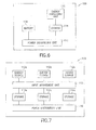
- FIG. 6 illustrates an exemplary embodiment of power system 108 for supplying necessary power to the pump mechanism 102, microcontroller 104 and PAN transceiver system 106.
- Power system 108 comprises an energy harvesting unit 112, storage unit 114 and power distribution unit 116.
- energy harvesting unit 112 preferably comprises an energy harvesting circuit that uses either kinetic energy or the Seebeck effect (thermal) to store charge and create voltage for use by the system components of medical device 100.
- the exemplary embodiments of medical device 100 as a wearable patch pump in contact with the user's skin lends itself the opportunity for efficient and optimum energy capture from the user's body.
- Kinetic and thermal energy harvesting techniques are well known, and accordingly, a detailed description of well known aspects of the same is omitted for clarity and conciseness.
- Kinetic energy harvesting techniques capture energy by reclaiming minute and unnoticeable amounts of energy from natural movement of the device user that can be converted to usable charge for medical device 100. Examples of kinetic energy that can be utilized include vibratory energy and limb deceleration. These embodiments may particularly be preferred when the medical device 100 is worn on the user's arm.
- Thermal energy harvesting techniques utilize the Seebeck effect to transform a temperature difference between the ambient environment and the patient's skin, where medical device 100 is adhered, into a usable voltage. Temperature differentials between opposite segments of a conducting material result in heat flow and consequently charge flow (current), since mobile, high-energy carriers diffuse from high to low concentration regions.
- One technique electrically joins thermopiles consisting of n- and p- type materials at the high temperature junction, thereby allowing heat flow to carry the dominant charge carriers of each material to the low temperature end, establishing a voltage difference across base electrodes of the thermopiles in the process.
- An exemplary embodiment of power system 108 utilizes a temporary storage circuit or device for storing the harvested charge until it is supplied to power a system component of medical device 100, such as PAN transceiver 106.
- An exemplary embodiment of the present invention utilizes an ultracapacitor as storage unit 114 to store the harvested energy. Ultracapacitors are advantageous because of their high energy density and quick charging times, thus providing a suitable option for powering the systems of an exemplary medical device 100.
- storage unit 114 may comprise any temporary storage component, circuitry or technique that is known in the art, and is not particularly limited to an ultracapacitor.
- Power distribution unit 116 may comprise a power management circuit or other known component for providing the necessary power requirement from power storage unit 114 to each system device.
- An exemplary embodiment of power system 108 in medical device 100 preferably comprises a single power source such as energy harvesting component 112, capturing, for instance, thermal or kinetic energy from the user's body and the user's natural movement.
- a single energy harvesting source may be sufficient for providing the complete power requirements for medical device 100.
- a single energy harvesting source may necessarily provide sufficient power for medical device 100 in embodiments that use a preprogrammed microcontroller 104 and do not provide a communications transceiver system.
- the power supplied to medical device should be sufficient for enabling operation of the medical device in an active mode and a standby mode.
- the microcontroller In the standby mode, the microcontroller preferably consumes about 10 microamperes of current but no more than 20 microamperes. In the active mode, the microcontroller preferably consumes about 10 milliamperes but no more than 20 milliamperes.
- power system 108 may additionally comprise a battery 118.
- Battery 118 may comprise any one of well known power storage units, or an array of such units, known in the art including, but not limited to, standard alkaline cells, rechargeable cells and ultracapacitors.
- power distribution unit 116 can optimally manage the distribution of power from the battery 118 and the energy harvesting storage unit 114 to provide increased performance and extended life of medical device 100.
- medical device 100 would use battery 118 for long-term storage power or "off" mode, and in an active mode, such as during a high-discharge time for pump mechanism 102 to dispense a drug to the user.
- Harvested energy storage unit 114 is then preferably used to supplement the idle/standby mode of medical device 100, which has been shown in some systems to be the highest overall power drain to the system.
- the device life could be extended or the battery requirements be reduced, thereby increasing performance and reducing cost in comparison to existing patch pumps.
- power system 108 for use in exemplary embodiments of the present invention is illustrated in FIG.7 .
- power system 108 comprises a plurality of energy harvesting units 112a, 112b and 112c.
- Energy harvesting units 112a-c can comprise any combination of kinetic harvesting units, thermal harvesting units and standard power sources such as batteries, as discussed above.
- the particular embodiment of medical device 100 comprises a transceiver system 106
- one of energy harvesting units 112a-c can be provided for harvesting energy from communications received from host device 200 at the transceiver.
- FIG. 7 illustrates three energy harvesting units by example only.
- power system 108 may comprise any number and combination of energy harvesting units that are suitable for the particular medical device.
- energy harvesting units 112a-c are not limited to harnessing kinetic energy, thermal energy or energy from communications with a host device. Additional systems for harnessing energy from electromagnetic energy, such as from RF energy, or any other sources that are feasible for powering medical device 100 may also be used. RF energy is pervasive in the external environment and may be captured by medical device 100 to directly power the device or provide a supplemental source of power for medical device 100. Exemplary techniques for harnessing RF energy suitable for use in the present invention can be found in U.S. Patent Publication No. 2006/0281435 to John G. Shearer, et al. , which is expressly incorporated herein by reference.
- input management unit 113 can comprise simple voltage rectifiers and charge pumps for translating the intermittently captured energy from energy harvesting devices 112a-c into a usable voltage for storage in any of storage units 114a-c.
- Storage units 114a-c may comprise various types of rechargeable batteries, ultracapacitors or other temporary storage devices recognized in the art.
- One of storage units 114a-c may optionally comprise a single use or disposable battery or battery array as similar described in FIG. 6 .
- System power distribution unit 116 is preferably provided for managing and dividing the available energy from storage units 114a-c amongst the systems in the medical device 100 that require different types of power.
- system power distribution unit 116 selectively supplies necessary power from a suitable storage unit to pump mechanism 102 that requires short bursts of higher current at a stable voltage to inject a drug into the user, while microcontroller 104 and exemplary PAN transceiver system 106 require smaller currents for optimum functionality.
- system power distribution unit 116 optimally designates an even lower power for powering medical device 100 in an "off" mode for long term storage of the device before it is used.
- the power system illustrated in FIG. 7 preferably realizes an optimal combination of energy harvesting units and standard power supply units, such as a battery, to provide optimum functionality for medical device 100 and extended life, at minimal cost.
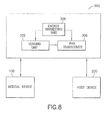
- FIG. 8 illustrates an exemplary embodiment of optional bodily function sensor 300 depicted in FIG. 3 for use in conjunction with exemplary embodiments of medical device 100.
- Bodily function sensor 300 may be a transcutaneous analyte sensor or biosensor and is preferably a blood glucose sensor that may be provided as part of medical device 100 or inserted at a separate site on the user, and may even be surgically implantable into the user.
- Sensor 300 may be provided as a temporary or disposable single use sensor or alternatively may be implemented for repeated or consistent use over an extended duration.
- sensor 300 optimally receives power from power system 108 and provides data to transceiver 106 for communication to host device 200.
- Host device 200 preferably processes any data received through the exemplary personal area network described above and modifies the user's infusion rate, if necessary.
- Host device may further perform any of the functions described in exemplary embodiments above.
- FIG. 8 illustrates sensor 300 as an implantable device or otherwise inserted into the user at a site separate from medical device 100.
- sensor 300 further comprises sensing unit 302, energy harvesting unit 308, and PAN transceiver system 306.
- Energy harvesting unit 308 may comprise any of the above described energy harvesting units and preferably provides the only source of power for the sensor 300.
- PAN transceiver 306 operates as discussed above to transmit sensing data received from sensing unit 302.
- PAN transceivers 106 and 206 are capable of receiving any data transmitted from PAN transceiver 306 through the exemplary personal area network described above.
- An exemplary embodiment of sensor 300 in accordance with the present invention, combines the advantages of the energy harvesting system 308 and PAN transceiver 306 to realize minimum cost and maximum functionality in providing precise insulin infusion control for a user using medical device 100.
- any other skin-surface, wearable, implantable and handheld devices can all utilize the above features and techniques for providing a body based personal area network of complex, low-power devices at minimal cost.
- other non-pump insulin infusion devices for patients of varying needs can be implemented with the above discussed features, such as a programmable insulin pen device or a controller in combination with an insulin absorption patch or electrosensitive gel patch.
- other physiological information such as systolic pressure, heart rate and other metrics can all be monitored and captured via a respective device using the exemplary personal area network.
- implantable defibrillators and other devices can all be controlled from a single master/host device.
- An exemplary personal area network can theoretically support many more than just two or three devices. Such network can also be used to communicate to any stationary devices when the user makes physical contact with them.
- One embodiment could provide automated data transmission such as populating patient records stored in a handheld or wearable device when touching a computer fitted with a compatible PAN transceiver.
- Another embodiment could provide emergency personnel with immediate data concerning a patient's physiological functions just by making skin to skin contact to establish a communications link between compatible devices on each person.
- each of these embodiments can be implemented in a secure PAN, so as to ensure user privacy and security of sensitive medical information.
Landscapes
- Health & Medical Sciences (AREA)
- Engineering & Computer Science (AREA)
- Life Sciences & Earth Sciences (AREA)
- Animal Behavior & Ethology (AREA)
- Anesthesiology (AREA)
- Biomedical Technology (AREA)
- Heart & Thoracic Surgery (AREA)
- Hematology (AREA)
- Veterinary Medicine (AREA)
- Vascular Medicine (AREA)
- General Health & Medical Sciences (AREA)
- Public Health (AREA)
- Dermatology (AREA)
- Diabetes (AREA)
- Computer Networks & Wireless Communication (AREA)
- Signal Processing (AREA)
- Infusion, Injection, And Reservoir Apparatuses (AREA)
- External Artificial Organs (AREA)
Priority Applications (1)
| Application Number | Priority Date | Filing Date | Title |
|---|---|---|---|
| ES14180178.7T ES2683830T3 (es) | 2009-07-23 | 2010-07-23 | Bomba de infusión portátil que tiene comunicación por acoplamiento capacitivo y mecanismo de recuperación de energía |
Applications Claiming Priority (2)
| Application Number | Priority Date | Filing Date | Title |
|---|---|---|---|
| US12/458,807 US8939928B2 (en) | 2009-07-23 | 2009-07-23 | Medical device having capacitive coupling communication and energy harvesting |
| EP10170614.1A EP2283881B1 (de) | 2009-07-23 | 2010-07-23 | Tragbare Infusionspumpe mit Kapazitätskupplungskommunikation und Energiesammlungseinrichtung |
Related Parent Applications (2)
| Application Number | Title | Priority Date | Filing Date |
|---|---|---|---|
| EP10170614.1A Division EP2283881B1 (de) | 2009-07-23 | 2010-07-23 | Tragbare Infusionspumpe mit Kapazitätskupplungskommunikation und Energiesammlungseinrichtung |
| EP10170614.1A Division-Into EP2283881B1 (de) | 2009-07-23 | 2010-07-23 | Tragbare Infusionspumpe mit Kapazitätskupplungskommunikation und Energiesammlungseinrichtung |
Publications (3)
| Publication Number | Publication Date |
|---|---|
| EP2803375A2 true EP2803375A2 (de) | 2014-11-19 |
| EP2803375A3 EP2803375A3 (de) | 2015-04-01 |
| EP2803375B1 EP2803375B1 (de) | 2018-05-23 |
Family
ID=43414778
Family Applications (2)
| Application Number | Title | Priority Date | Filing Date |
|---|---|---|---|
| EP14180178.7A Active EP2803375B1 (de) | 2009-07-23 | 2010-07-23 | Tragbare Infusionspumpe mit Kapazitätskupplungskommunikation und Energiesammlungseinrichtung |
| EP10170614.1A Active EP2283881B1 (de) | 2009-07-23 | 2010-07-23 | Tragbare Infusionspumpe mit Kapazitätskupplungskommunikation und Energiesammlungseinrichtung |
Family Applications After (1)
| Application Number | Title | Priority Date | Filing Date |
|---|---|---|---|
| EP10170614.1A Active EP2283881B1 (de) | 2009-07-23 | 2010-07-23 | Tragbare Infusionspumpe mit Kapazitätskupplungskommunikation und Energiesammlungseinrichtung |
Country Status (5)
| Country | Link |
|---|---|
| US (4) | US8939928B2 (de) |
| EP (2) | EP2803375B1 (de) |
| JP (2) | JP5855814B2 (de) |
| CA (1) | CA2710717C (de) |
| ES (2) | ES2703604T3 (de) |
Families Citing this family (85)
| Publication number | Priority date | Publication date | Assignee | Title |
|---|---|---|---|---|
| US7148879B2 (en) | 2000-07-06 | 2006-12-12 | At&T Corp. | Bioacoustic control system, method and apparatus |
| US7008403B1 (en) * | 2002-07-19 | 2006-03-07 | Cognitive Ventures Corporation | Infusion pump and method for use |
| US20080228056A1 (en) | 2007-03-13 | 2008-09-18 | Michael Blomquist | Basal rate testing using frequent blood glucose input |
| US7751907B2 (en) | 2007-05-24 | 2010-07-06 | Smiths Medical Asd, Inc. | Expert system for insulin pump therapy |
| US8221345B2 (en) | 2007-05-30 | 2012-07-17 | Smiths Medical Asd, Inc. | Insulin pump based expert system |
| KR101263893B1 (ko) * | 2008-05-28 | 2013-05-13 | 삼성전자주식회사 | 인체 통신 시스템에서 송신 전력을 제어하기 위한 장치 및방법 |
| US9375529B2 (en) * | 2009-09-02 | 2016-06-28 | Becton, Dickinson And Company | Extended use medical device |
| US8758323B2 (en) | 2009-07-30 | 2014-06-24 | Tandem Diabetes Care, Inc. | Infusion pump system with disposable cartridge having pressure venting and pressure feedback |
| US8882701B2 (en) | 2009-12-04 | 2014-11-11 | Smiths Medical Asd, Inc. | Advanced step therapy delivery for an ambulatory infusion pump and system |
| EP2545652B1 (de) * | 2010-03-12 | 2018-02-28 | Sunrise Micro Devices Inc. | Leistungseffiziente kommunikationen |
| TW201221091A (en) | 2010-04-23 | 2012-06-01 | Access Business Group Int Llc | Energy harvesting seating |
| US8908894B2 (en) | 2011-12-01 | 2014-12-09 | At&T Intellectual Property I, L.P. | Devices and methods for transferring data through a human body |
| WO2013123359A2 (en) | 2012-02-17 | 2013-08-22 | Calhoun Benton H | Energy harvesting and control for sensor node |
| US9026531B2 (en) * | 2012-04-17 | 2015-05-05 | Cerner Innovation, Inc. | Associating multiple data sources into a web-accessible framework |
| US9180242B2 (en) | 2012-05-17 | 2015-11-10 | Tandem Diabetes Care, Inc. | Methods and devices for multiple fluid transfer |
| US10561353B2 (en) | 2016-06-01 | 2020-02-18 | Glysens Incorporated | Biocompatible implantable sensor apparatus and methods |
| WO2014103063A1 (ja) * | 2012-12-28 | 2014-07-03 | 横浜ゴム株式会社 | 空気入りタイヤ |
| US9962533B2 (en) * | 2013-02-14 | 2018-05-08 | William Harrison Zurn | Module for treatment of medical conditions; system for making module and methods of making module |
| US9287734B2 (en) * | 2013-02-19 | 2016-03-15 | Gojo Industries, Inc. | Thermal energy harvesting for dispensing system |
| CN109330600A (zh) | 2013-03-14 | 2019-02-15 | M·祖贝尔·米尔扎 | 基于互联网的疾病监测系统(idms) |
| US9173998B2 (en) | 2013-03-14 | 2015-11-03 | Tandem Diabetes Care, Inc. | System and method for detecting occlusions in an infusion pump |
| US9373269B2 (en) * | 2013-03-18 | 2016-06-21 | Lifescan Scotland Limited | Patch pump training device |
| KR102120922B1 (ko) | 2013-03-25 | 2020-06-17 | 삼성전자주식회사 | 에너지 공유 네트워크를 형성하는 웨어러블 장치 및 방법 |
| US9662538B2 (en) * | 2013-06-13 | 2017-05-30 | Intelidigital Corp. | System for optimal exercise and training |
| US9811636B2 (en) * | 2013-09-20 | 2017-11-07 | Beam Ip Lab Llc | Connected health care system |
| CA2865757C (en) * | 2013-09-30 | 2020-06-09 | Michael Jordan Kadonoff | Electrical current measuring apparatus and method |
| US10108984B2 (en) | 2013-10-29 | 2018-10-23 | At&T Intellectual Property I, L.P. | Detecting body language via bone conduction |
| US9594433B2 (en) | 2013-11-05 | 2017-03-14 | At&T Intellectual Property I, L.P. | Gesture-based controls via bone conduction |
| US9349280B2 (en) | 2013-11-18 | 2016-05-24 | At&T Intellectual Property I, L.P. | Disrupting bone conduction signals |
| US10678322B2 (en) | 2013-11-18 | 2020-06-09 | At&T Intellectual Property I, L.P. | Pressure sensing via bone conduction |
| US9715774B2 (en) | 2013-11-19 | 2017-07-25 | At&T Intellectual Property I, L.P. | Authenticating a user on behalf of another user based upon a unique body signature determined through bone conduction signals |
| US9405892B2 (en) | 2013-11-26 | 2016-08-02 | At&T Intellectual Property I, L.P. | Preventing spoofing attacks for bone conduction applications |
| WO2015081326A1 (en) * | 2013-11-27 | 2015-06-04 | Shenzhen Huiding Technology Co., Ltd. | Wearable communication devices for secured transaction and communication |
| JP2017503250A (ja) * | 2013-12-20 | 2017-01-26 | コーニンクレッカ フィリップス エヌ ヴェKoninklijke Philips N.V. | 摂取プランに従ったユーザによる製品の摂取のモニタリングを可能にするためのロギングシステム及びデータ登録の方法 |
| FI3597138T3 (fi) * | 2014-03-06 | 2023-03-08 | W & H Dentalwerk Buermoos Gmbh | Lääketieteellinen, erityisesti dentaalinen, järjestelmä |
| US9588507B2 (en) * | 2014-03-26 | 2017-03-07 | Mediatek Inc. | Low-power mechanism for wearable controller and associated control method |
| US9979225B2 (en) * | 2014-07-28 | 2018-05-22 | Christophe & Albrecht, Inc. | Energy generation system for wearable communication device |
| US9582071B2 (en) | 2014-09-10 | 2017-02-28 | At&T Intellectual Property I, L.P. | Device hold determination using bone conduction |
| CA2960223C (en) | 2014-09-10 | 2023-04-04 | Becton, Dickinson And Company | Activation system and method for on-body medical devices |
| US9882992B2 (en) | 2014-09-10 | 2018-01-30 | At&T Intellectual Property I, L.P. | Data session handoff using bone conduction |
| US10045732B2 (en) | 2014-09-10 | 2018-08-14 | At&T Intellectual Property I, L.P. | Measuring muscle exertion using bone conduction |
| US9589482B2 (en) | 2014-09-10 | 2017-03-07 | At&T Intellectual Property I, L.P. | Bone conduction tags |
| US9600079B2 (en) | 2014-10-15 | 2017-03-21 | At&T Intellectual Property I, L.P. | Surface determination via bone conduction |
| CN104571507B (zh) * | 2014-12-27 | 2019-07-23 | 北京智谷睿拓技术服务有限公司 | 交互方法及用户设备 |
| US9706269B2 (en) * | 2015-07-24 | 2017-07-11 | Hong Kong Applied Science and Technology Research Institute Company, Limited | Self-powered and battery-assisted CMOS wireless bio-sensing IC platform |
| US10716896B2 (en) | 2015-11-24 | 2020-07-21 | Insulet Corporation | Wearable automated medication delivery system |
| US10569016B2 (en) | 2015-12-29 | 2020-02-25 | Tandem Diabetes Care, Inc. | System and method for switching between closed loop and open loop control of an ambulatory infusion pump |
| KR101869870B1 (ko) * | 2016-04-27 | 2018-06-22 | (주)씨어스테크놀로지 | 무정지 보장형 스마트패치 |
| US11071857B2 (en) | 2016-08-22 | 2021-07-27 | William Marsh Rice University | Systems and methods for wireless treatment of arrhythmias |
| US10779635B2 (en) | 2016-09-26 | 2020-09-22 | The Government Of The United States, As Represented By The Secretary Of The Army | Energy generation |
| CN109792301A (zh) * | 2016-10-14 | 2019-05-21 | 艾斯曲尔医疗公司 | 配置为通过人体发送数据的自助给药装置 |
| US20180153450A1 (en) * | 2016-12-02 | 2018-06-07 | Glysens Incorporated | Analyte sensor receiver apparatus and methods |
| USD853583S1 (en) | 2017-03-29 | 2019-07-09 | Becton, Dickinson And Company | Hand-held device housing |
| TWD186862S (zh) * | 2017-04-05 | 2017-11-21 | 華廣生技股份有限公司 | 分析物測量儀之部分 |
| GB2563578B (en) * | 2017-06-14 | 2022-04-20 | Bevan Heba | Medical devices |
| EP3415186A1 (de) | 2017-06-15 | 2018-12-19 | Koninklijke Philips N.V. | Gewinnung von energie aus betrieb einer spritze |
| US11504472B2 (en) | 2017-07-06 | 2022-11-22 | Quasuras, Inc. | Medical pump with flow control |
| EP4285960A3 (de) * | 2017-12-21 | 2024-02-28 | Sanofi | Sammlung von injektionsvorrichtungsdaten mithilfe von aus einer externen vorrichtung gewonnener energie |
| US11278668B2 (en) | 2017-12-22 | 2022-03-22 | Glysens Incorporated | Analyte sensor and medicant delivery data evaluation and error reduction apparatus and methods |
| US11255839B2 (en) | 2018-01-04 | 2022-02-22 | Glysens Incorporated | Apparatus and methods for analyte sensor mismatch correction |
| US11115074B1 (en) * | 2018-07-05 | 2021-09-07 | Snap Inc. | Wearable device antenna |
| US10831316B2 (en) | 2018-07-26 | 2020-11-10 | At&T Intellectual Property I, L.P. | Surface interface |
| US12320769B2 (en) | 2018-11-19 | 2025-06-03 | The Regents Of The University Of California | Systems and methods for battery-less wirelessly powered dielectric sensors |
| CA3120643A1 (en) | 2018-11-20 | 2020-05-28 | The Regents Of The University Of California | Systems and methods for controlling wirelessly powered leadless pacemakers |
| US10833732B2 (en) * | 2019-01-09 | 2020-11-10 | Wolfgang Richter | System for extending the range of near field communication of an electronic device to communicate with an object over a user skin |
| US11128168B2 (en) | 2019-02-12 | 2021-09-21 | Washington University | Methods and apparatus for wireless power delivery and remote sensing using self-capacitances |
| US12678067B1 (en) * | 2019-03-20 | 2026-07-14 | Biological Art Group, Inc. | Telemetry implants |
| WO2020202042A1 (en) * | 2019-04-01 | 2020-10-08 | Dvir Yossi | Personal wearable medical emergency device |
| AU2020257200A1 (en) | 2019-04-17 | 2021-12-16 | Icu Medical, Inc. | System for onboard electronic encoding of the contents and administration parameters of IV containers and the secure use and disposal thereof |
| US12052533B2 (en) | 2019-07-08 | 2024-07-30 | The Regents Of The University Of California | Systems and methods for long-distance remote sensing with sub-wavelength resolution using a wirelessly-powered sensor tag array |
| WO2021044305A1 (en) | 2019-09-03 | 2021-03-11 | Trudell Medical International | Medical device with energy harvesting system |
| GB2588621B (en) * | 2019-10-29 | 2024-06-19 | Prevayl Innovations Ltd | Wearable article, textile article and method |
| EP4069333B1 (de) | 2019-12-06 | 2026-02-04 | Quasuras, Inc. | Rotierende mikrofluidische medizinische pumpe |
| CA3153012A1 (en) | 2019-12-23 | 2021-07-01 | Fresenius Medical Care Holdings, Inc. | Connected drug delivery system for erythropoietin stimulating agents |
| US11817197B2 (en) * | 2020-02-07 | 2023-11-14 | Quasuras, Inc. | Medical pump electronic pairing with device |
| EP4110165A4 (de) | 2020-02-28 | 2024-05-15 | The Regents of the University of California | Integrierte energiegewinnende transceiver und sender mit doppelter antennenarchitektur für miniaturisierte implantate und elektrochemische sensoren |
| CN115279269A (zh) * | 2020-03-09 | 2022-11-01 | 麦克斯韦生物医学有限公司 | 心脏起搏设备 |
| US12508362B2 (en) * | 2020-09-08 | 2025-12-30 | Medtrum Technologies Inc. | Infusion needle structure of drug infusion device |
| EP4262921A1 (de) | 2020-12-18 | 2023-10-25 | Insulet Corporation | Klebepad mit einer metallischen spule zur befestigung einer am körper getragenen medizinischen vorrichtung |
| WO2022147985A1 (en) * | 2021-01-05 | 2022-07-14 | Medtrum Technologies Inc. | A skin patch drug infusion device |
| US20220233765A1 (en) * | 2021-01-26 | 2022-07-28 | Insulet Corporation | Conductive element in adhesive patch of on-body drug delivery device for body channel communication |
| CN118077035A (zh) | 2021-10-08 | 2024-05-24 | 三星钻石工业股份有限公司 | 半导体装置 |
| WO2023102145A2 (en) * | 2021-12-01 | 2023-06-08 | Noble International, Llc | Energy harvesting substance event monitoring system |
| EP4197572A1 (de) * | 2021-12-17 | 2023-06-21 | Becton, Dickinson and Company | Thermoelektrischer generator zur speisung eines autoinjektors |
| EP4554663A4 (de) | 2022-07-14 | 2026-07-15 | Maxwell Biomedical Inc | Erweiterte stimulation |
Citations (2)
| Publication number | Priority date | Publication date | Assignee | Title |
|---|---|---|---|---|
| US6589229B1 (en) | 2000-07-31 | 2003-07-08 | Becton, Dickinson And Company | Wearable, self-contained drug infusion device |
| US20060281435A1 (en) | 2005-06-08 | 2006-12-14 | Firefly Power Technologies, Inc. | Powering devices using RF energy harvesting |
Family Cites Families (167)
| Publication number | Priority date | Publication date | Assignee | Title |
|---|---|---|---|---|
| US3857382A (en) | 1972-10-27 | 1974-12-31 | Sinai Hospital Of Detroit | Piezoelectric heart assist apparatus |
| US3963380A (en) | 1975-01-06 | 1976-06-15 | Thomas Jr Lyell J | Micro pump powered by piezoelectric disk benders |
| US4204538A (en) | 1978-06-07 | 1980-05-27 | Imed Corporation | Cassette for intravenous controller |
| US4755173A (en) | 1986-02-25 | 1988-07-05 | Pacesetter Infusion, Ltd. | Soft cannula subcutaneous injection set |
| US4723947A (en) | 1986-04-09 | 1988-02-09 | Pacesetter Infusion, Ltd. | Insulin compatible infusion set |
| US5453099A (en) | 1990-03-26 | 1995-09-26 | Becton, Dickinson And Company | Catheter tubing of controlled in vivo softening |
| US5226899A (en) | 1990-03-26 | 1993-07-13 | Becton, Dickinson And Company | Catheter tubing of controlled in vivo softening |
| US5176662A (en) | 1990-08-23 | 1993-01-05 | Minimed Technologies, Ltd. | Subcutaneous injection set with improved cannula mounting arrangement |
| US6068615A (en) | 1994-07-22 | 2000-05-30 | Health Hero Network, Inc. | Inductance-based dose measurement in syringes |
| US5956501A (en) | 1997-01-10 | 1999-09-21 | Health Hero Network, Inc. | Disease simulation system and method |
| US5545143A (en) | 1993-01-21 | 1996-08-13 | T. S. I. Medical | Device for subcutaneous medication delivery |
| DK25793A (da) | 1993-03-09 | 1994-09-10 | Pharma Plast Int As | Infusionssæt til intermitterende eller kontinuerlig indgivelse af et terapeutisk middel |
| US5257980A (en) | 1993-04-05 | 1993-11-02 | Minimed Technologies, Ltd. | Subcutaneous injection set with crimp-free soft cannula |
| US5536249A (en) | 1994-03-09 | 1996-07-16 | Visionary Medical Products, Inc. | Pen-type injector with a microprocessor and blood characteristic monitor |
| US6110148A (en) | 1994-07-22 | 2000-08-29 | Health Hero Network, Inc. | Capacitance-based dose measurements in syringes |
| US5545152A (en) | 1994-10-28 | 1996-08-13 | Minimed Inc. | Quick-connect coupling for a medication infusion system |
| AU1860697A (en) | 1995-09-08 | 1997-07-28 | Visionary Medical Products Corporation | Pen-type injector drive mechanism |
| US5858001A (en) | 1995-12-11 | 1999-01-12 | Elan Medical Technologies Limited | Cartridge-based drug delivery device |
| US7329239B2 (en) | 1997-02-05 | 2008-02-12 | Medtronic Minimed, Inc. | Insertion device for an insertion set and method of using the same |
| US6607509B2 (en) | 1997-12-31 | 2003-08-19 | Medtronic Minimed, Inc. | Insertion device for an insertion set and method of using the same |
| US5851197A (en) | 1997-02-05 | 1998-12-22 | Minimed Inc. | Injector for a subcutaneous infusion set |
| US6093172A (en) | 1997-02-05 | 2000-07-25 | Minimed Inc. | Injector for a subcutaneous insertion set |
| US20070142776A9 (en) | 1997-02-05 | 2007-06-21 | Medtronic Minimed, Inc. | Insertion device for an insertion set and method of using the same |
| US7267665B2 (en) | 1999-06-03 | 2007-09-11 | Medtronic Minimed, Inc. | Closed loop system for controlling insulin infusion |
| US6558351B1 (en) | 1999-06-03 | 2003-05-06 | Medtronic Minimed, Inc. | Closed loop system for controlling insulin infusion |
| EP0990151A2 (de) | 1997-06-16 | 2000-04-05 | ELAN CORPORATION, Plc | Verfahren zum kalibrieren und testen eines sensors für in vivo messung eines analytes, und vorrichtungen zum gebrauch dergleichen verfahren |
| US5968011A (en) | 1997-06-20 | 1999-10-19 | Maersk Medical A/S | Subcutaneous injection set |
| US5858005A (en) | 1997-08-27 | 1999-01-12 | Science Incorporated | Subcutaneous infusion set with dynamic needle |
| JP4647098B2 (ja) | 1997-12-31 | 2011-03-09 | メドトロニック ミニメド インコーポレイテッド | 挿入セットのための挿入装置 |
| DK1044374T3 (da) | 1997-12-31 | 2009-02-16 | Univ Duke | Glucosebiosensor |
| US7780623B2 (en) | 1998-01-29 | 2010-08-24 | Soltanpour David P | Implantable pump apparatuses |
| US5957895A (en) | 1998-02-20 | 1999-09-28 | Becton Dickinson And Company | Low-profile automatic injection device with self-emptying reservoir |
| US6056718A (en) | 1998-03-04 | 2000-05-02 | Minimed Inc. | Medication infusion set |
| US6104913A (en) | 1998-03-11 | 2000-08-15 | Bell Atlantic Network Services, Inc. | Personal area network for personal telephone services |
| US5980506A (en) | 1998-03-20 | 1999-11-09 | Mathiasen; Orla | Subcutaneous infusion device |
| US6086575A (en) | 1998-03-20 | 2000-07-11 | Maersk Medical A/S | Subcutaneous infusion device |
| US6123690A (en) | 1998-03-20 | 2000-09-26 | Maersk Medical A/S | Subcutaneous infusion device |
| US6391005B1 (en) | 1998-03-30 | 2002-05-21 | Agilent Technologies, Inc. | Apparatus and method for penetration with shaft having a sensor for sensing penetration depth |
| US6175752B1 (en) | 1998-04-30 | 2001-01-16 | Therasense, Inc. | Analyte monitoring device and methods of use |
| EP1078258B1 (de) | 1998-05-13 | 2003-07-30 | Cygnus, Inc. | Vorrichtung zum vorhersagen von physiologischen messwerten |
| DE19821723C2 (de) | 1998-05-14 | 2000-07-06 | Disetronic Licensing Ag | Katheterkopf für subkutane Verabreichung eines Wirkstoffs |
| US6949084B2 (en) | 1998-05-14 | 2005-09-27 | Disetronic Licensing Ag | Catheter head for subcutaneous administration of an active substance |
| US6355021B1 (en) | 1998-07-14 | 2002-03-12 | Maersk Medical A/S | Medical puncturing device |
| US6554798B1 (en) | 1998-08-18 | 2003-04-29 | Medtronic Minimed, Inc. | External infusion device with remote programming, bolus estimator and/or vibration alarm capabilities |
| EP0980687B1 (de) | 1998-08-20 | 2004-03-03 | Sooil Development Co., Ltd. | Tragbare, automatische Spritzenvorrichtung |
| US6254586B1 (en) | 1998-09-25 | 2001-07-03 | Minimed Inc. | Method and kit for supplying a fluid to a subcutaneous placement site |
| US6115636A (en) | 1998-12-22 | 2000-09-05 | Medtronic, Inc. | Telemetry for implantable devices using the body as an antenna |
| US6749560B1 (en) | 1999-10-26 | 2004-06-15 | Circon Corporation | Endoscope shaft with slotted tube |
| EP1248661B1 (de) | 2000-01-21 | 2012-08-22 | Medtronic MiniMed, Inc. | Ambulantes medizinisches gerät und verfahren mit telemetrisch veränderbarer steuerungssoftware |
| US6706159B2 (en) | 2000-03-02 | 2004-03-16 | Diabetes Diagnostics | Combined lancet and electrochemical analyte-testing apparatus |
| US6485461B1 (en) | 2000-04-04 | 2002-11-26 | Insulet, Inc. | Disposable infusion device |
| US6754472B1 (en) | 2000-04-27 | 2004-06-22 | Microsoft Corporation | Method and apparatus for transmitting power and data using the human body |
| EP1335764B1 (de) | 2000-09-08 | 2007-06-06 | Insulet Corporation | Infusionsvorrichtung und System |
| US6669669B2 (en) | 2001-10-12 | 2003-12-30 | Insulet Corporation | Laminated patient infusion device |
| US20040260233A1 (en) | 2000-09-08 | 2004-12-23 | Garibotto John T. | Data collection assembly for patient infusion system |
| US20020040208A1 (en) | 2000-10-04 | 2002-04-04 | Flaherty J. Christopher | Data collection assembly for patient infusion system |
| DK1695727T3 (da) | 2000-11-09 | 2008-12-01 | Insulet Corp | Anordning til transkutan administrering |
| US7860729B2 (en) | 2000-11-13 | 2010-12-28 | Peter Stangel | Clinical care utilization management system |
| US6576430B1 (en) | 2000-11-20 | 2003-06-10 | Becton, Dickinson And Company | Detection of ligands by refractive surface methods |
| ATE311811T1 (de) | 2000-12-21 | 2005-12-15 | Insulet Corp | Medizinisches gerät zur fernbedienung |
| US6579267B2 (en) | 2001-01-05 | 2003-06-17 | Applied Diabetes Research, Inc. | Pivoting joint infusion assembly |
| US7083597B2 (en) | 2001-01-05 | 2006-08-01 | Applied Diabetes Research, Inc. | Pivoting joint infusion system with seal |
| CA2434731C (en) | 2001-02-22 | 2010-01-26 | Insulet Corporation | Modular infusion device and method |
| US20030014091A1 (en) | 2001-05-25 | 2003-01-16 | Rastegar Jahangir S. | Implantable wireless and battery-free communication system for diagnostics sensors |
| US6544212B2 (en) | 2001-07-31 | 2003-04-08 | Roche Diagnostics Corporation | Diabetes management system |
| WO2003021247A1 (en) | 2001-08-28 | 2003-03-13 | Duke University | Biosensor |
| US20030055380A1 (en) | 2001-09-19 | 2003-03-20 | Flaherty J. Christopher | Plunger for patient infusion device |
| US20030109829A1 (en) | 2001-09-28 | 2003-06-12 | Mogensen Lasse Wesseltoft | Injector device for placing a subcutaneous infusion set |
| US6830562B2 (en) | 2001-09-27 | 2004-12-14 | Unomedical A/S | Injector device for placing a subcutaneous infusion set |
| US20040078028A1 (en) | 2001-11-09 | 2004-04-22 | Flaherty J. Christopher | Plunger assembly for patient infusion device |
| GB0127989D0 (en) | 2001-11-22 | 2002-01-16 | Glaxo Group Ltd | Medicament dispensing system |
| US7064103B2 (en) | 2002-01-04 | 2006-06-20 | Becton, Dickinson And Company | Binding protein as biosensors |
| US7004928B2 (en) | 2002-02-08 | 2006-02-28 | Rosedale Medical, Inc. | Autonomous, ambulatory analyte monitor or drug delivery device |
| US6852104B2 (en) | 2002-02-28 | 2005-02-08 | Smiths Medical Md, Inc. | Programmable insulin pump |
| US6822343B2 (en) | 2002-02-28 | 2004-11-23 | Texas Instruments Incorporated | Generating electric power in response to activity of a biological system |
| US6692457B2 (en) | 2002-03-01 | 2004-02-17 | Insulet Corporation | Flow condition sensor assembly for patient infusion device |
| US6830558B2 (en) | 2002-03-01 | 2004-12-14 | Insulet Corporation | Flow condition sensor assembly for patient infusion device |
| DK1490133T3 (da) | 2002-03-08 | 2015-06-22 | Applied Diabetes Res Inc | Infusionsanordning med lavprofildrejeforbindelse |
| US20040093041A1 (en) * | 2002-03-15 | 2004-05-13 | Macdonald Stuart G. | Biothermal power source for implantable devices |
| US7052251B2 (en) | 2002-04-22 | 2006-05-30 | Medtronic Minimed, Inc. | Shape memory alloy wire driven positive displacement micropump with pulsatile output |
| US6656159B2 (en) | 2002-04-23 | 2003-12-02 | Insulet Corporation | Dispenser for patient infusion device |
| US20050238507A1 (en) | 2002-04-23 | 2005-10-27 | Insulet Corporation | Fluid delivery device |
| US6960192B1 (en) | 2002-04-23 | 2005-11-01 | Insulet Corporation | Transcutaneous fluid delivery system |
| US20040153032A1 (en) | 2002-04-23 | 2004-08-05 | Garribotto John T. | Dispenser for patient infusion device |
| US6656158B2 (en) | 2002-04-23 | 2003-12-02 | Insulet Corporation | Dispenser for patient infusion device |
| US6723072B2 (en) | 2002-06-06 | 2004-04-20 | Insulet Corporation | Plunger assembly for patient infusion device |
| US20080132842A1 (en) | 2002-06-06 | 2008-06-05 | Flaherty J Christopher | Plunger assembly for patient infusion device |
| US6790173B2 (en) | 2002-06-13 | 2004-09-14 | Usgi Medical, Inc. | Shape lockable apparatus and method for advancing an instrument through unsupported anatomy |
| US20040010207A1 (en) | 2002-07-15 | 2004-01-15 | Flaherty J. Christopher | Self-contained, automatic transcutaneous physiologic sensing system |
| US7018360B2 (en) | 2002-07-16 | 2006-03-28 | Insulet Corporation | Flow restriction system and method for patient infusion device |
| US20040059316A1 (en) | 2002-07-31 | 2004-03-25 | Smedegaard Jorgen K. | Medical delivery device |
| CA2488393C (en) * | 2002-08-08 | 2011-02-01 | Glaukos Corporation | Implantable ocular pump to reduce intraocular pressure |
| US7128727B2 (en) | 2002-09-30 | 2006-10-31 | Flaherty J Christopher | Components and methods for patient infusion device |
| US7144384B2 (en) | 2002-09-30 | 2006-12-05 | Insulet Corporation | Dispenser components and methods for patient infusion device |
| US20040116866A1 (en) | 2002-12-17 | 2004-06-17 | William Gorman | Skin attachment apparatus and method for patient infusion device |
| US7070580B2 (en) | 2003-04-01 | 2006-07-04 | Unomedical A/S | Infusion device and an adhesive sheet material and a release liner |
| JP2007525241A (ja) | 2003-04-18 | 2007-09-06 | インシュレット コーポレイション | 注入ポンプ用リモコンのためのユーザーインターフェース及びそれの使用方法 |
| US20050182366A1 (en) | 2003-04-18 | 2005-08-18 | Insulet Corporation | Method For Visual Output Verification |
| US20050222645A1 (en) | 2003-04-30 | 2005-10-06 | Luis Malave | Microchip-based medical device |
| US20040220551A1 (en) | 2003-04-30 | 2004-11-04 | Flaherty J. Christopher | Low profile components for patient infusion device |
| DE602004013140T2 (de) | 2003-05-08 | 2009-07-02 | Novo Nordisk A/S | Interne nadeleinführvorrichtung |
| CN100574819C (zh) | 2003-05-08 | 2009-12-30 | 诺沃挪第克公司 | 可枢转注射针头单元 |
| EP1623227A4 (de) | 2003-05-09 | 2009-03-04 | Univ Maryland | Proteine, sensoren und verfahren zur charakterisierung von analyten damit |
| WO2005002649A1 (en) | 2003-07-08 | 2005-01-13 | Novo Nordisk A/S | Portable drug delivery device having an encapsulated needle |
| EP1502613A1 (de) | 2003-08-01 | 2005-02-02 | Novo Nordisk A/S | Gerät mit Rückziehvorrichting für eine Nadel |
| US20050051727A1 (en) * | 2003-09-05 | 2005-03-10 | Jones Richard S. | Infrared elimination system |
| US20050065760A1 (en) | 2003-09-23 | 2005-03-24 | Robert Murtfeldt | Method for advising patients concerning doses of insulin |
| KR20060099520A (ko) | 2003-10-21 | 2006-09-19 | 노보 노르디스크 에이/에스 | 의료용 피부 장착 장치 |
| US7731691B2 (en) | 2003-11-10 | 2010-06-08 | Smiths Medical Asd, Inc. | Subcutaneous infusion device and device for insertion of a cannula of an infusion device and method |
| US7699808B2 (en) | 2003-11-10 | 2010-04-20 | Smiths Medical Asd, Inc. | Subcutaneous infusion device and method |
| US7494481B2 (en) | 2004-12-03 | 2009-02-24 | Medtronic Minimed, Inc. | Multi-position infusion set device and process |
| US7850658B2 (en) | 2003-11-10 | 2010-12-14 | Smiths Medical Asd, Inc. | Subcutaneous infusion device and method including release feature for adhesive portion |
| US7496392B2 (en) | 2003-11-26 | 2009-02-24 | Becton, Dickinson And Company | Fiber optic device for sensing analytes |
| DE102004002472B4 (de) | 2004-01-16 | 2007-09-13 | Disetronic Licensing Ag | Einstechnadel |
| JP2005312950A (ja) | 2004-03-31 | 2005-11-10 | Terumo Corp | エネルギー照射用医療器具および医療用エネルギー照射装置 |
| US20050245799A1 (en) | 2004-05-03 | 2005-11-03 | Dexcom, Inc. | Implantable analyte sensor |
| US7125382B2 (en) | 2004-05-20 | 2006-10-24 | Digital Angel Corporation | Embedded bio-sensor system |
| US20050273076A1 (en) | 2004-06-07 | 2005-12-08 | C.R. Bard, Inc. | Subcutaneous infusion devices |
| US7946984B2 (en) | 2004-07-13 | 2011-05-24 | Dexcom, Inc. | Transcutaneous analyte sensor |
| US9820658B2 (en) * | 2006-06-30 | 2017-11-21 | Bao Q. Tran | Systems and methods for providing interoperability among healthcare devices |
| EP1804859A1 (de) | 2004-09-22 | 2007-07-11 | Novo Nordisk A/S | Medizinische vorrichtung mit kanüleneinführer |
| US20080215006A1 (en) | 2004-09-22 | 2008-09-04 | Novo Nordisk A/S | Medical Device with Transcutaneous Cannula Device |
| US7303543B1 (en) | 2004-12-03 | 2007-12-04 | Medtronic Minimed, Inc. | Medication infusion set |
| US9259175B2 (en) | 2006-10-23 | 2016-02-16 | Abbott Diabetes Care, Inc. | Flexible patch for fluid delivery and monitoring body analytes |
| US20060178633A1 (en) | 2005-02-03 | 2006-08-10 | Insulet Corporation | Chassis for fluid delivery device |
| US8956291B2 (en) | 2005-02-22 | 2015-02-17 | Admetsys Corporation | Balanced physiological monitoring and treatment system |
| EP1866010A1 (de) | 2005-02-28 | 2007-12-19 | Novo Nordisk A/S | Vorrichtung zur veränderung der arzneimittel-abgaberate |
| EP1698279A1 (de) | 2005-03-04 | 2006-09-06 | Disetronic Licensing AG | Sequentielle Einführung von Hauptpenetratoren |
| US7985199B2 (en) | 2005-03-17 | 2011-07-26 | Unomedical A/S | Gateway system |
| US20060224141A1 (en) * | 2005-03-21 | 2006-10-05 | Abbott Diabetes Care, Inc. | Method and system for providing integrated medication infusion and analyte monitoring system |
| US8303533B2 (en) | 2005-03-29 | 2012-11-06 | Medizinische Universitaet Graz | Device and method for delivery of a physiologically active substance depending on a measured physiological parameter |
| US8840586B2 (en) | 2006-08-23 | 2014-09-23 | Medtronic Minimed, Inc. | Systems and methods allowing for reservoir filling and infusion medium delivery |
| US8137314B2 (en) | 2006-08-23 | 2012-03-20 | Medtronic Minimed, Inc. | Infusion medium delivery device and method with compressible or curved reservoir or conduit |
| US7905868B2 (en) | 2006-08-23 | 2011-03-15 | Medtronic Minimed, Inc. | Infusion medium delivery device and method with drive device for driving plunger in reservoir |
| US8512288B2 (en) | 2006-08-23 | 2013-08-20 | Medtronic Minimed, Inc. | Infusion medium delivery device and method with drive device for driving plunger in reservoir |
| US8277415B2 (en) | 2006-08-23 | 2012-10-02 | Medtronic Minimed, Inc. | Infusion medium delivery device and method with drive device for driving plunger in reservoir |
| US20080097291A1 (en) | 2006-08-23 | 2008-04-24 | Hanson Ian B | Infusion pumps and methods and delivery devices and methods with same |
| US20060263839A1 (en) | 2005-05-17 | 2006-11-23 | Isense Corporation | Combined drug delivery and analyte sensor apparatus |
| US20060283465A1 (en) | 2005-06-16 | 2006-12-21 | Nickel Janice H | Smart drug delivery system and a method of implementation thereof |
| JP2008543460A (ja) | 2005-06-20 | 2008-12-04 | ノボ・ノルデイスク・エー/エス | 延性部分を備えるカニューレ |
| WO2007051139A2 (en) | 2005-10-27 | 2007-05-03 | Insulet Corporation | Diabetes management systems and methods |
| AU2006329075A1 (en) | 2005-12-23 | 2007-06-28 | Unomedical A/S | Injection device |
| WO2007093981A2 (en) | 2006-02-15 | 2007-08-23 | Medingo Ltd. | Systems and methods for sensing analyte and dispensing therapeutic fluid |
| US20080140057A1 (en) * | 2006-03-09 | 2008-06-12 | Searete Llc, A Limited Liability Corporation Of State Of The Delaware | Injectable controlled release fluid delivery system |
| US20080046038A1 (en) * | 2006-06-26 | 2008-02-21 | Hill Gerard J | Local communications network for distributed sensing and therapy in biomedical applications |
| JP5241714B2 (ja) | 2006-07-07 | 2013-07-17 | プロテウス デジタル ヘルス, インコーポレイテッド | スマートな非経口送達システム |
| US20080160492A1 (en) | 2006-08-08 | 2008-07-03 | Insulet Corporation | Interactive training system and method |
| US7736338B2 (en) | 2006-08-23 | 2010-06-15 | Medtronic Minimed, Inc. | Infusion medium delivery system, device and method with needle inserter and needle inserter device and method |
| US7828764B2 (en) | 2006-08-23 | 2010-11-09 | Medtronic Minimed, Inc. | Systems and methods allowing for reservoir filling and infusion medium delivery |
| US20080051765A1 (en) | 2006-08-23 | 2008-02-28 | Medtronic Minimed, Inc. | Systems and methods allowing for reservoir filling and infusion medium delivery |
| US7794434B2 (en) | 2006-08-23 | 2010-09-14 | Medtronic Minimed, Inc. | Systems and methods allowing for reservoir filling and infusion medium delivery |
| US7811262B2 (en) | 2006-08-23 | 2010-10-12 | Medtronic Minimed, Inc. | Systems and methods allowing for reservoir filling and infusion medium delivery |
| US20080058772A1 (en) | 2006-08-31 | 2008-03-06 | Robertson Timothy L | Personal paramedic |
| US20080071328A1 (en) * | 2006-09-06 | 2008-03-20 | Medtronic, Inc. | Initiating medical system communications |
| US7771412B2 (en) | 2006-10-18 | 2010-08-10 | Insulet Corporation | Environmental seal for fluid delivery device |
| JP2008161641A (ja) * | 2007-01-04 | 2008-07-17 | Kazumichi Sato | 全自動型病態通報救助システム |
| JP2010522599A (ja) * | 2007-03-27 | 2010-07-08 | コーニンクレッカ フィリップス エレクトロニクス エヌ ヴィ | 消費電力の低い自動薬剤投与 |
| US7959715B2 (en) | 2007-04-30 | 2011-06-14 | Medtronic Minimed, Inc. | Systems and methods allowing for reservoir air bubble management |
| US7963954B2 (en) | 2007-04-30 | 2011-06-21 | Medtronic Minimed, Inc. | Automated filling systems and methods |
| US8434528B2 (en) | 2007-04-30 | 2013-05-07 | Medtronic Minimed, Inc. | Systems and methods for reservoir filling |
| US7884727B2 (en) * | 2007-05-24 | 2011-02-08 | Bao Tran | Wireless occupancy and day-light sensing |
| US8562558B2 (en) | 2007-06-08 | 2013-10-22 | Dexcom, Inc. | Integrated medicament delivery device for use with continuous analyte sensor |
| WO2009002627A1 (en) | 2007-06-27 | 2008-12-31 | Roche Diagnostics Gmbh | Therapy delivery system having an open architecture and a method thereof |
| US8465981B2 (en) | 2007-08-06 | 2013-06-18 | University Of Kentucky Research Foundation | Polypeptides, systems, and methods useful for detecting glucose |
| US20090048648A1 (en) | 2007-08-17 | 2009-02-19 | Searete Llc, A Limited Liability Corporation Of The State Of Delaware | Self-sterilizing device |
| EP2222370A1 (de) | 2007-10-24 | 2010-09-01 | Medtronic, Inc. | Übertragung von informationen zur anwendung von stromquellen über ein netz |
| EP2211974A4 (de) * | 2007-10-25 | 2013-02-27 | Proteus Digital Health Inc | Informationssystem für flüssigkeitsüberströmkanal |
-
2009
- 2009-07-23 US US12/458,807 patent/US8939928B2/en active Active
-
2010
- 2010-07-21 CA CA2710717A patent/CA2710717C/en active Active
- 2010-07-23 JP JP2010166064A patent/JP5855814B2/ja active Active
- 2010-07-23 ES ES10170614T patent/ES2703604T3/es active Active
- 2010-07-23 EP EP14180178.7A patent/EP2803375B1/de active Active
- 2010-07-23 EP EP10170614.1A patent/EP2283881B1/de active Active
- 2010-07-23 ES ES14180178.7T patent/ES2683830T3/es active Active
-
2014
- 2014-12-23 US US14/581,700 patent/US9764083B1/en active Active
-
2015
- 2015-06-08 JP JP2015116044A patent/JP6085004B2/ja active Active
-
2017
- 2017-08-25 US US15/686,873 patent/US11052190B2/en active Active
-
2021
- 2021-06-11 US US17/345,178 patent/US11951280B2/en active Active
Patent Citations (2)
| Publication number | Priority date | Publication date | Assignee | Title |
|---|---|---|---|---|
| US6589229B1 (en) | 2000-07-31 | 2003-07-08 | Becton, Dickinson And Company | Wearable, self-contained drug infusion device |
| US20060281435A1 (en) | 2005-06-08 | 2006-12-14 | Firefly Power Technologies, Inc. | Powering devices using RF energy harvesting |
Also Published As
| Publication number | Publication date |
|---|---|
| JP2015157168A (ja) | 2015-09-03 |
| US20180008770A1 (en) | 2018-01-11 |
| US8939928B2 (en) | 2015-01-27 |
| ES2703604T3 (es) | 2019-03-11 |
| ES2683830T3 (es) | 2018-09-28 |
| EP2283881A3 (de) | 2014-01-22 |
| CA2710717A1 (en) | 2011-01-23 |
| JP5855814B2 (ja) | 2016-02-09 |
| EP2803375B1 (de) | 2018-05-23 |
| US11951280B2 (en) | 2024-04-09 |
| JP2011025038A (ja) | 2011-02-10 |
| CA2710717C (en) | 2018-02-27 |
| US11052190B2 (en) | 2021-07-06 |
| US20210308369A1 (en) | 2021-10-07 |
| US20110022025A1 (en) | 2011-01-27 |
| EP2803375A3 (de) | 2015-04-01 |
| JP6085004B2 (ja) | 2017-02-22 |
| US9764083B1 (en) | 2017-09-19 |
| EP2283881B1 (de) | 2018-10-03 |
| EP2283881A2 (de) | 2011-02-16 |
Similar Documents
| Publication | Publication Date | Title |
|---|---|---|
| US11951280B2 (en) | Medical device having capacitive coupling communication and energy harvesting | |
| US11109316B2 (en) | Methods of wireless communication in an infusion pump system | |
| US11838867B2 (en) | Methods for reduction of battery usage in ambulatory infusion pumps | |
| US6768425B2 (en) | Medical apparatus remote control and method | |
| EP2131923B1 (de) | Verfahren und system zur einleitung einer kommunikation zwischen einem heimüberwachungsgerät und einem implantierbaren medizinprodukt | |
| US20090062778A1 (en) | Medical System Comprising Dual-Purpose Communication Means | |
| US20080269673A1 (en) | Cellular-Enabled Medical Monitoring and Infusion System | |
| US20090069868A1 (en) | Secure Pairing of Electronic Devices using Dual Means of Communication | |
| US20190380628A1 (en) | Analyte sensor apparatus and methods | |
| EP2967460A1 (de) | In-vivo-glucose-erfassung in einer hautschicht mit erhöhter perfusion | |
| WO2008069931A1 (en) | Analyte sensing apparatus for hospital use | |
| US20220226573A1 (en) | Infusion device | |
| KR20170104602A (ko) | 사람의 혈당 수치를 조절하는 시스템 및 방법 | |
| US20100198279A1 (en) | Transceiver duty cycled operational mode | |
| CN113456071A (zh) | 血糖检测及激素输注集成装置、制备方法及人工胰腺 | |
| US20260027300A1 (en) | Medical device and medical system using said medical device | |
| CN215458028U (zh) | 血糖检测及激素输注集成装置及人工胰腺 | |
| US20260061203A1 (en) | Configurable single actuation mechanism programming remote for medical devices | |
| US20260131074A1 (en) | Integrated cgm and insulin pump system with inductive power transfer | |
| HK1125058A (en) | Cellular-enabled medical monitoring an infusion system |
Legal Events
| Date | Code | Title | Description |
|---|---|---|---|
| PUAI | Public reference made under article 153(3) epc to a published international application that has entered the european phase |
Free format text: ORIGINAL CODE: 0009012 |
|
| 17P | Request for examination filed |
Effective date: 20140807 |
|
| AC | Divisional application: reference to earlier application |
Ref document number: 2283881 Country of ref document: EP Kind code of ref document: P |
|
| AK | Designated contracting states |
Kind code of ref document: A2 Designated state(s): AL AT BE BG CH CY CZ DE DK EE ES FI FR GB GR HR HU IE IS IT LI LT LU LV MC MK MT NL NO PL PT RO SE SI SK SM TR |
|
| AX | Request for extension of the european patent |
Extension state: BA ME RS |
|
| PUAL | Search report despatched |
Free format text: ORIGINAL CODE: 0009013 |
|
| AK | Designated contracting states |
Kind code of ref document: A3 Designated state(s): AL AT BE BG CH CY CZ DE DK EE ES FI FR GB GR HR HU IE IS IT LI LT LU LV MC MK MT NL NO PL PT RO SE SI SK SM TR |
|
| AX | Request for extension of the european patent |
Extension state: BA ME RS |
|
| RIC1 | Information provided on ipc code assigned before grant |
Ipc: H04B 13/00 20060101ALI20150223BHEP Ipc: A61B 5/145 20060101ALN20150223BHEP Ipc: A61M 5/142 20060101AFI20150223BHEP Ipc: A61M 5/172 20060101ALN20150223BHEP |
|
| RIN1 | Information on inventor provided before grant (corrected) |
Inventor name: SAVOIE, RICHARD Inventor name: SEARLE, GARY |
|
| R17P | Request for examination filed (corrected) |
Effective date: 20150930 |
|
| RBV | Designated contracting states (corrected) |
Designated state(s): AL AT BE BG CH CY CZ DE DK EE ES FI FR GB GR HR HU IE IS IT LI LT LU LV MC MK MT NL NO PL PT RO SE SI SK SM TR |
|
| RAP1 | Party data changed (applicant data changed or rights of an application transferred) |
Owner name: BECTON, DICKINSON AND COMPANY |
|
| STAA | Information on the status of an ep patent application or granted ep patent |
Free format text: STATUS: EXAMINATION IS IN PROGRESS |
|
| 17Q | First examination report despatched |
Effective date: 20170407 |
|
| GRAP | Despatch of communication of intention to grant a patent |
Free format text: ORIGINAL CODE: EPIDOSNIGR1 |
|
| STAA | Information on the status of an ep patent application or granted ep patent |
Free format text: STATUS: GRANT OF PATENT IS INTENDED |
|
| RIC1 | Information provided on ipc code assigned before grant |
Ipc: A61B 5/00 20060101ALI20171114BHEP Ipc: A61M 5/142 20060101AFI20171114BHEP Ipc: H04B 13/00 20060101ALI20171114BHEP Ipc: A61M 5/172 20060101ALI20171114BHEP Ipc: A61B 5/145 20060101ALI20171114BHEP |
|
| INTG | Intention to grant announced |
Effective date: 20171213 |
|
| GRAS | Grant fee paid |
Free format text: ORIGINAL CODE: EPIDOSNIGR3 |
|
| GRAA | (expected) grant |
Free format text: ORIGINAL CODE: 0009210 |
|
| STAA | Information on the status of an ep patent application or granted ep patent |
Free format text: STATUS: THE PATENT HAS BEEN GRANTED |
|
| AC | Divisional application: reference to earlier application |
Ref document number: 2283881 Country of ref document: EP Kind code of ref document: P |
|
| AK | Designated contracting states |
Kind code of ref document: B1 Designated state(s): AL AT BE BG CH CY CZ DE DK EE ES FI FR GB GR HR HU IE IS IT LI LT LU LV MC MK MT NL NO PL PT RO SE SI SK SM TR |
|
| REG | Reference to a national code |
Ref country code: GB Ref legal event code: FG4D |
|
| REG | Reference to a national code |
Ref country code: CH Ref legal event code: EP |
|
| REG | Reference to a national code |
Ref country code: IE Ref legal event code: FG4D |
|
| REG | Reference to a national code |
Ref country code: AT Ref legal event code: REF Ref document number: 1001009 Country of ref document: AT Kind code of ref document: T Effective date: 20180615 |
|
| REG | Reference to a national code |
Ref country code: DE Ref legal event code: R096 Ref document number: 602010050844 Country of ref document: DE Ref country code: FR Ref legal event code: PLFP Year of fee payment: 9 |
|
| REG | Reference to a national code |
Ref country code: NL Ref legal event code: MP Effective date: 20180523 |
|
| REG | Reference to a national code |
Ref country code: ES Ref legal event code: FG2A Ref document number: 2683830 Country of ref document: ES Kind code of ref document: T3 Effective date: 20180928 |
|
| REG | Reference to a national code |
Ref country code: LT Ref legal event code: MG4D |
|
| PG25 | Lapsed in a contracting state [announced via postgrant information from national office to epo] |
Ref country code: LT Free format text: LAPSE BECAUSE OF FAILURE TO SUBMIT A TRANSLATION OF THE DESCRIPTION OR TO PAY THE FEE WITHIN THE PRESCRIBED TIME-LIMIT Effective date: 20180523 Ref country code: SE Free format text: LAPSE BECAUSE OF FAILURE TO SUBMIT A TRANSLATION OF THE DESCRIPTION OR TO PAY THE FEE WITHIN THE PRESCRIBED TIME-LIMIT Effective date: 20180523 Ref country code: NO Free format text: LAPSE BECAUSE OF FAILURE TO SUBMIT A TRANSLATION OF THE DESCRIPTION OR TO PAY THE FEE WITHIN THE PRESCRIBED TIME-LIMIT Effective date: 20180823 Ref country code: BG Free format text: LAPSE BECAUSE OF FAILURE TO SUBMIT A TRANSLATION OF THE DESCRIPTION OR TO PAY THE FEE WITHIN THE PRESCRIBED TIME-LIMIT Effective date: 20180823 Ref country code: FI Free format text: LAPSE BECAUSE OF FAILURE TO SUBMIT A TRANSLATION OF THE DESCRIPTION OR TO PAY THE FEE WITHIN THE PRESCRIBED TIME-LIMIT Effective date: 20180523 |
|
| PG25 | Lapsed in a contracting state [announced via postgrant information from national office to epo] |
Ref country code: HR Free format text: LAPSE BECAUSE OF FAILURE TO SUBMIT A TRANSLATION OF THE DESCRIPTION OR TO PAY THE FEE WITHIN THE PRESCRIBED TIME-LIMIT Effective date: 20180523 Ref country code: GR Free format text: LAPSE BECAUSE OF FAILURE TO SUBMIT A TRANSLATION OF THE DESCRIPTION OR TO PAY THE FEE WITHIN THE PRESCRIBED TIME-LIMIT Effective date: 20180824 Ref country code: LV Free format text: LAPSE BECAUSE OF FAILURE TO SUBMIT A TRANSLATION OF THE DESCRIPTION OR TO PAY THE FEE WITHIN THE PRESCRIBED TIME-LIMIT Effective date: 20180523 Ref country code: NL Free format text: LAPSE BECAUSE OF FAILURE TO SUBMIT A TRANSLATION OF THE DESCRIPTION OR TO PAY THE FEE WITHIN THE PRESCRIBED TIME-LIMIT Effective date: 20180523 |
|
| REG | Reference to a national code |
Ref country code: AT Ref legal event code: MK05 Ref document number: 1001009 Country of ref document: AT Kind code of ref document: T Effective date: 20180523 |
|
| PG25 | Lapsed in a contracting state [announced via postgrant information from national office to epo] |
Ref country code: SK Free format text: LAPSE BECAUSE OF FAILURE TO SUBMIT A TRANSLATION OF THE DESCRIPTION OR TO PAY THE FEE WITHIN THE PRESCRIBED TIME-LIMIT Effective date: 20180523 Ref country code: RO Free format text: LAPSE BECAUSE OF FAILURE TO SUBMIT A TRANSLATION OF THE DESCRIPTION OR TO PAY THE FEE WITHIN THE PRESCRIBED TIME-LIMIT Effective date: 20180523 Ref country code: CZ Free format text: LAPSE BECAUSE OF FAILURE TO SUBMIT A TRANSLATION OF THE DESCRIPTION OR TO PAY THE FEE WITHIN THE PRESCRIBED TIME-LIMIT Effective date: 20180523 Ref country code: PL Free format text: LAPSE BECAUSE OF FAILURE TO SUBMIT A TRANSLATION OF THE DESCRIPTION OR TO PAY THE FEE WITHIN THE PRESCRIBED TIME-LIMIT Effective date: 20180523 Ref country code: DK Free format text: LAPSE BECAUSE OF FAILURE TO SUBMIT A TRANSLATION OF THE DESCRIPTION OR TO PAY THE FEE WITHIN THE PRESCRIBED TIME-LIMIT Effective date: 20180523 Ref country code: EE Free format text: LAPSE BECAUSE OF FAILURE TO SUBMIT A TRANSLATION OF THE DESCRIPTION OR TO PAY THE FEE WITHIN THE PRESCRIBED TIME-LIMIT Effective date: 20180523 Ref country code: AT Free format text: LAPSE BECAUSE OF FAILURE TO SUBMIT A TRANSLATION OF THE DESCRIPTION OR TO PAY THE FEE WITHIN THE PRESCRIBED TIME-LIMIT Effective date: 20180523 |
|
| REG | Reference to a national code |
Ref country code: DE Ref legal event code: R097 Ref document number: 602010050844 Country of ref document: DE |
|
| PG25 | Lapsed in a contracting state [announced via postgrant information from national office to epo] |
Ref country code: SM Free format text: LAPSE BECAUSE OF FAILURE TO SUBMIT A TRANSLATION OF THE DESCRIPTION OR TO PAY THE FEE WITHIN THE PRESCRIBED TIME-LIMIT Effective date: 20180523 |
|
| REG | Reference to a national code |
Ref country code: CH Ref legal event code: PL |
|
| PG25 | Lapsed in a contracting state [announced via postgrant information from national office to epo] |
Ref country code: MC Free format text: LAPSE BECAUSE OF FAILURE TO SUBMIT A TRANSLATION OF THE DESCRIPTION OR TO PAY THE FEE WITHIN THE PRESCRIBED TIME-LIMIT Effective date: 20180523 Ref country code: LU Free format text: LAPSE BECAUSE OF NON-PAYMENT OF DUE FEES Effective date: 20180723 |
|
| PLBE | No opposition filed within time limit |
Free format text: ORIGINAL CODE: 0009261 |
|
| STAA | Information on the status of an ep patent application or granted ep patent |
Free format text: STATUS: NO OPPOSITION FILED WITHIN TIME LIMIT |
|
| REG | Reference to a national code |
Ref country code: BE Ref legal event code: MM Effective date: 20180731 |
|
| REG | Reference to a national code |
Ref country code: IE Ref legal event code: MM4A |
|
| PG25 | Lapsed in a contracting state [announced via postgrant information from national office to epo] |
Ref country code: IE Free format text: LAPSE BECAUSE OF NON-PAYMENT OF DUE FEES Effective date: 20180723 Ref country code: CH Free format text: LAPSE BECAUSE OF NON-PAYMENT OF DUE FEES Effective date: 20180731 Ref country code: LI Free format text: LAPSE BECAUSE OF NON-PAYMENT OF DUE FEES Effective date: 20180731 |
|
| 26N | No opposition filed |
Effective date: 20190226 |
|
| PG25 | Lapsed in a contracting state [announced via postgrant information from national office to epo] |
Ref country code: BE Free format text: LAPSE BECAUSE OF NON-PAYMENT OF DUE FEES Effective date: 20180731 Ref country code: SI Free format text: LAPSE BECAUSE OF FAILURE TO SUBMIT A TRANSLATION OF THE DESCRIPTION OR TO PAY THE FEE WITHIN THE PRESCRIBED TIME-LIMIT Effective date: 20180523 |
|
| PG25 | Lapsed in a contracting state [announced via postgrant information from national office to epo] |
Ref country code: AL Free format text: LAPSE BECAUSE OF FAILURE TO SUBMIT A TRANSLATION OF THE DESCRIPTION OR TO PAY THE FEE WITHIN THE PRESCRIBED TIME-LIMIT Effective date: 20180523 |
|
| PG25 | Lapsed in a contracting state [announced via postgrant information from national office to epo] |
Ref country code: MT Free format text: LAPSE BECAUSE OF NON-PAYMENT OF DUE FEES Effective date: 20180723 |
|
| PG25 | Lapsed in a contracting state [announced via postgrant information from national office to epo] |
Ref country code: TR Free format text: LAPSE BECAUSE OF FAILURE TO SUBMIT A TRANSLATION OF THE DESCRIPTION OR TO PAY THE FEE WITHIN THE PRESCRIBED TIME-LIMIT Effective date: 20180523 |
|
| PG25 | Lapsed in a contracting state [announced via postgrant information from national office to epo] |
Ref country code: HU Free format text: LAPSE BECAUSE OF FAILURE TO SUBMIT A TRANSLATION OF THE DESCRIPTION OR TO PAY THE FEE WITHIN THE PRESCRIBED TIME-LIMIT; INVALID AB INITIO Effective date: 20100723 Ref country code: PT Free format text: LAPSE BECAUSE OF FAILURE TO SUBMIT A TRANSLATION OF THE DESCRIPTION OR TO PAY THE FEE WITHIN THE PRESCRIBED TIME-LIMIT Effective date: 20180523 |
|
| PG25 | Lapsed in a contracting state [announced via postgrant information from national office to epo] |
Ref country code: MK Free format text: LAPSE BECAUSE OF NON-PAYMENT OF DUE FEES Effective date: 20180523 Ref country code: CY Free format text: LAPSE BECAUSE OF FAILURE TO SUBMIT A TRANSLATION OF THE DESCRIPTION OR TO PAY THE FEE WITHIN THE PRESCRIBED TIME-LIMIT Effective date: 20180523 |
|
| PG25 | Lapsed in a contracting state [announced via postgrant information from national office to epo] |
Ref country code: IS Free format text: LAPSE BECAUSE OF FAILURE TO SUBMIT A TRANSLATION OF THE DESCRIPTION OR TO PAY THE FEE WITHIN THE PRESCRIBED TIME-LIMIT Effective date: 20180923 |
|
| PGFP | Annual fee paid to national office [announced via postgrant information from national office to epo] |
Ref country code: ES Payment date: 20250801 Year of fee payment: 16 |
|
| PGFP | Annual fee paid to national office [announced via postgrant information from national office to epo] |
Ref country code: DE Payment date: 20250620 Year of fee payment: 16 |
|
| PGFP | Annual fee paid to national office [announced via postgrant information from national office to epo] |
Ref country code: GB Payment date: 20260618 Year of fee payment: 17 |
|
| PGFP | Annual fee paid to national office [announced via postgrant information from national office to epo] |
Ref country code: IT Payment date: 20260618 Year of fee payment: 17 |
|
| PGFP | Annual fee paid to national office [announced via postgrant information from national office to epo] |
Ref country code: FR Payment date: 20260618 Year of fee payment: 17 |