EP2802753B1 - Système d'échappement d'un moteur à combustion interne et procédé de préparation d'un agent réducteur introduit dans les gaz d'échappement dudit moteur - Google Patents
Système d'échappement d'un moteur à combustion interne et procédé de préparation d'un agent réducteur introduit dans les gaz d'échappement dudit moteur Download PDFInfo
- Publication number
- EP2802753B1 EP2802753B1 EP13701361.1A EP13701361A EP2802753B1 EP 2802753 B1 EP2802753 B1 EP 2802753B1 EP 13701361 A EP13701361 A EP 13701361A EP 2802753 B1 EP2802753 B1 EP 2802753B1
- Authority
- EP
- European Patent Office
- Prior art keywords
- pipe section
- exhaust pipe
- exhaust
- reducing agent
- exhaust gas
- Prior art date
- Legal status (The legal status is an assumption and is not a legal conclusion. Google has not performed a legal analysis and makes no representation as to the accuracy of the status listed.)
- Active
Links
- 239000003638 chemical reducing agent Substances 0.000 title claims description 85
- 238000002485 combustion reaction Methods 0.000 title claims description 15
- 238000000034 method Methods 0.000 title claims description 15
- 238000011144 upstream manufacturing Methods 0.000 claims description 14
- 230000001154 acute effect Effects 0.000 claims description 3
- 239000007789 gas Substances 0.000 description 83
- 230000008020 evaporation Effects 0.000 description 19
- 238000001704 evaporation Methods 0.000 description 19
- 238000002360 preparation method Methods 0.000 description 12
- 239000003054 catalyst Substances 0.000 description 11
- QGZKDVFQNNGYKY-UHFFFAOYSA-N Ammonia Chemical compound N QGZKDVFQNNGYKY-UHFFFAOYSA-N 0.000 description 10
- XSQUKJJJFZCRTK-UHFFFAOYSA-N Urea Chemical compound NC(N)=O XSQUKJJJFZCRTK-UHFFFAOYSA-N 0.000 description 9
- 239000004202 carbamide Substances 0.000 description 9
- 239000007788 liquid Substances 0.000 description 8
- 238000012545 processing Methods 0.000 description 8
- 230000015572 biosynthetic process Effects 0.000 description 7
- 238000013461 design Methods 0.000 description 7
- 238000000746 purification Methods 0.000 description 7
- 239000007921 spray Substances 0.000 description 7
- MWUXSHHQAYIFBG-UHFFFAOYSA-N Nitric oxide Chemical compound O=[N] MWUXSHHQAYIFBG-UHFFFAOYSA-N 0.000 description 6
- 239000011248 coating agent Substances 0.000 description 6
- 238000000576 coating method Methods 0.000 description 6
- 230000007062 hydrolysis Effects 0.000 description 6
- 238000006460 hydrolysis reaction Methods 0.000 description 6
- 238000002156 mixing Methods 0.000 description 6
- 229910021529 ammonia Inorganic materials 0.000 description 5
- 238000009826 distribution Methods 0.000 description 5
- 239000000243 solution Substances 0.000 description 5
- 230000003197 catalytic effect Effects 0.000 description 4
- 238000004140 cleaning Methods 0.000 description 4
- 230000003647 oxidation Effects 0.000 description 4
- 238000007254 oxidation reaction Methods 0.000 description 4
- 238000001149 thermolysis Methods 0.000 description 4
- 230000009467 reduction Effects 0.000 description 3
- 238000009827 uniform distribution Methods 0.000 description 3
- GWEVSGVZZGPLCZ-UHFFFAOYSA-N Titan oxide Chemical compound O=[Ti]=O GWEVSGVZZGPLCZ-UHFFFAOYSA-N 0.000 description 2
- 238000006073 displacement reaction Methods 0.000 description 2
- 230000006872 improvement Effects 0.000 description 2
- 238000002347 injection Methods 0.000 description 2
- 239000007924 injection Substances 0.000 description 2
- 239000002245 particle Substances 0.000 description 2
- 230000008569 process Effects 0.000 description 2
- 238000005507 spraying Methods 0.000 description 2
- 238000012546 transfer Methods 0.000 description 2
- 230000007704 transition Effects 0.000 description 2
- 238000009736 wetting Methods 0.000 description 2
- 239000000654 additive Substances 0.000 description 1
- 230000000996 additive effect Effects 0.000 description 1
- 230000003750 conditioning effect Effects 0.000 description 1
- 238000010276 construction Methods 0.000 description 1
- 238000000354 decomposition reaction Methods 0.000 description 1
- 230000003247 decreasing effect Effects 0.000 description 1
- 230000008021 deposition Effects 0.000 description 1
- 238000010586 diagram Methods 0.000 description 1
- 230000000694 effects Effects 0.000 description 1
- 238000004049 embossing Methods 0.000 description 1
- 239000012530 fluid Substances 0.000 description 1
- 239000000446 fuel Substances 0.000 description 1
- 238000010438 heat treatment Methods 0.000 description 1
- 230000003116 impacting effect Effects 0.000 description 1
- 238000009434 installation Methods 0.000 description 1
- 238000012423 maintenance Methods 0.000 description 1
- 239000000463 material Substances 0.000 description 1
- 239000002480 mineral oil Substances 0.000 description 1
- 235000010446 mineral oil Nutrition 0.000 description 1
- 230000002093 peripheral effect Effects 0.000 description 1
- 238000007788 roughening Methods 0.000 description 1
- 238000007493 shaping process Methods 0.000 description 1
- 238000004904 shortening Methods 0.000 description 1
- 238000004088 simulation Methods 0.000 description 1
- 230000003068 static effect Effects 0.000 description 1
- 238000003860 storage Methods 0.000 description 1
- 230000003746 surface roughness Effects 0.000 description 1
- 230000009044 synergistic interaction Effects 0.000 description 1
- 239000004408 titanium dioxide Substances 0.000 description 1
- 238000012549 training Methods 0.000 description 1
- 238000003466 welding Methods 0.000 description 1
Images


Classifications
-
- F—MECHANICAL ENGINEERING; LIGHTING; HEATING; WEAPONS; BLASTING
- F01—MACHINES OR ENGINES IN GENERAL; ENGINE PLANTS IN GENERAL; STEAM ENGINES
- F01N—GAS-FLOW SILENCERS OR EXHAUST APPARATUS FOR MACHINES OR ENGINES IN GENERAL; GAS-FLOW SILENCERS OR EXHAUST APPARATUS FOR INTERNAL COMBUSTION ENGINES
- F01N3/00—Exhaust or silencing apparatus having means for purifying, rendering innocuous, or otherwise treating exhaust
- F01N3/08—Exhaust or silencing apparatus having means for purifying, rendering innocuous, or otherwise treating exhaust for rendering innocuous
- F01N3/10—Exhaust or silencing apparatus having means for purifying, rendering innocuous, or otherwise treating exhaust for rendering innocuous by thermal or catalytic conversion of noxious components of exhaust
- F01N3/24—Exhaust or silencing apparatus having means for purifying, rendering innocuous, or otherwise treating exhaust for rendering innocuous by thermal or catalytic conversion of noxious components of exhaust characterised by constructional aspects of converting apparatus
- F01N3/28—Construction of catalytic reactors
-
- F—MECHANICAL ENGINEERING; LIGHTING; HEATING; WEAPONS; BLASTING
- F01—MACHINES OR ENGINES IN GENERAL; ENGINE PLANTS IN GENERAL; STEAM ENGINES
- F01N—GAS-FLOW SILENCERS OR EXHAUST APPARATUS FOR MACHINES OR ENGINES IN GENERAL; GAS-FLOW SILENCERS OR EXHAUST APPARATUS FOR INTERNAL COMBUSTION ENGINES
- F01N3/00—Exhaust or silencing apparatus having means for purifying, rendering innocuous, or otherwise treating exhaust
- F01N3/08—Exhaust or silencing apparatus having means for purifying, rendering innocuous, or otherwise treating exhaust for rendering innocuous
- F01N3/10—Exhaust or silencing apparatus having means for purifying, rendering innocuous, or otherwise treating exhaust for rendering innocuous by thermal or catalytic conversion of noxious components of exhaust
- F01N3/18—Exhaust or silencing apparatus having means for purifying, rendering innocuous, or otherwise treating exhaust for rendering innocuous by thermal or catalytic conversion of noxious components of exhaust characterised by methods of operation; Control
- F01N3/20—Exhaust or silencing apparatus having means for purifying, rendering innocuous, or otherwise treating exhaust for rendering innocuous by thermal or catalytic conversion of noxious components of exhaust characterised by methods of operation; Control specially adapted for catalytic conversion ; Methods of operation or control of catalytic converters
- F01N3/2066—Selective catalytic reduction [SCR]
- F01N3/208—Control of selective catalytic reduction [SCR], e.g. dosing of reducing agent
-
- F—MECHANICAL ENGINEERING; LIGHTING; HEATING; WEAPONS; BLASTING
- F01—MACHINES OR ENGINES IN GENERAL; ENGINE PLANTS IN GENERAL; STEAM ENGINES
- F01N—GAS-FLOW SILENCERS OR EXHAUST APPARATUS FOR MACHINES OR ENGINES IN GENERAL; GAS-FLOW SILENCERS OR EXHAUST APPARATUS FOR INTERNAL COMBUSTION ENGINES
- F01N2470/00—Structure or shape of gas passages, pipes or tubes
- F01N2470/18—Structure or shape of gas passages, pipes or tubes the axis of inlet or outlet tubes being other than the longitudinal axis of apparatus
-
- F—MECHANICAL ENGINEERING; LIGHTING; HEATING; WEAPONS; BLASTING
- F01—MACHINES OR ENGINES IN GENERAL; ENGINE PLANTS IN GENERAL; STEAM ENGINES
- F01N—GAS-FLOW SILENCERS OR EXHAUST APPARATUS FOR MACHINES OR ENGINES IN GENERAL; GAS-FLOW SILENCERS OR EXHAUST APPARATUS FOR INTERNAL COMBUSTION ENGINES
- F01N2610/00—Adding substances to exhaust gases
- F01N2610/02—Adding substances to exhaust gases the substance being ammonia or urea
-
- F—MECHANICAL ENGINEERING; LIGHTING; HEATING; WEAPONS; BLASTING
- F01—MACHINES OR ENGINES IN GENERAL; ENGINE PLANTS IN GENERAL; STEAM ENGINES
- F01N—GAS-FLOW SILENCERS OR EXHAUST APPARATUS FOR MACHINES OR ENGINES IN GENERAL; GAS-FLOW SILENCERS OR EXHAUST APPARATUS FOR INTERNAL COMBUSTION ENGINES
- F01N2610/00—Adding substances to exhaust gases
- F01N2610/10—Adding substances to exhaust gases the substance being heated, e.g. by heating tank or supply line of the added substance
- F01N2610/102—Adding substances to exhaust gases the substance being heated, e.g. by heating tank or supply line of the added substance after addition to exhaust gases, e.g. by a passively or actively heated surface in the exhaust conduit
-
- F—MECHANICAL ENGINEERING; LIGHTING; HEATING; WEAPONS; BLASTING
- F01—MACHINES OR ENGINES IN GENERAL; ENGINE PLANTS IN GENERAL; STEAM ENGINES
- F01N—GAS-FLOW SILENCERS OR EXHAUST APPARATUS FOR MACHINES OR ENGINES IN GENERAL; GAS-FLOW SILENCERS OR EXHAUST APPARATUS FOR INTERNAL COMBUSTION ENGINES
- F01N2610/00—Adding substances to exhaust gases
- F01N2610/14—Arrangements for the supply of substances, e.g. conduits
- F01N2610/1453—Sprayers or atomisers; Arrangement thereof in the exhaust apparatus
-
- Y—GENERAL TAGGING OF NEW TECHNOLOGICAL DEVELOPMENTS; GENERAL TAGGING OF CROSS-SECTIONAL TECHNOLOGIES SPANNING OVER SEVERAL SECTIONS OF THE IPC; TECHNICAL SUBJECTS COVERED BY FORMER USPC CROSS-REFERENCE ART COLLECTIONS [XRACs] AND DIGESTS
- Y02—TECHNOLOGIES OR APPLICATIONS FOR MITIGATION OR ADAPTATION AGAINST CLIMATE CHANGE
- Y02T—CLIMATE CHANGE MITIGATION TECHNOLOGIES RELATED TO TRANSPORTATION
- Y02T10/00—Road transport of goods or passengers
- Y02T10/10—Internal combustion engine [ICE] based vehicles
- Y02T10/12—Improving ICE efficiencies
Definitions
- the invention relates to an exhaust system of an internal combustion engine which has a first cylindrical exhaust pipe section and a second cylindrical exhaust pipe section for the exhaust system, wherein enriched with the reducing agent exhaust gas from the first exhaust pipe pipe section in the second exhaust pipe pipe section can be transferred. Furthermore, the invention relates to a method for processing a reductant introduced into an exhaust system of an internal combustion engine.
- the EP 2395211 A1 discloses an exhaust system having a connection pipe between a first exhaust aftertreatment device and a second one Exhaust after-treatment device, in which reducing agent is supplied via a supply device.
- the downstream part of the connection pipe extends along the outer peripheral surface of the second exhaust aftertreatment device.
- the JP 2009228484 A1 shows an exhaust system for an internal combustion engine with a reducing agent supply means for the supply of reducing agent to an exhaust gas stream in a cylindrical tube.
- the cylindrical tube is arranged perpendicular to a likewise cylindrical housing, in which an SCR catalyst is housed.
- the exit end of the cylindrical tube is connected to the cylindrical housing upstream of the SCR catalyst so that the exhaust gas flow laden with reducing agent enters the cylindrical housing tangentially from the cylindrical tube.
- the DE 102009041345 A1 discloses an exhaust system in which the introduction of an additive takes place in the region of a bypass provided for a main duct of an exhaust line. In the bypass several baffles are provided.
- the object of the invention is therefore to provide a device and a method with which the best possible treatment of introduced in the exhaust gas of an internal combustion engine reducing agent is made possible.
- the exhaust system comprises a first cylindrical exhaust pipe pipe section and a second cylindrical exhaust pipe pipe section for the exhaust gas guide.
- an injector unit for introducing a reducing agent into exhaust gas flowing through the first exhaust pipe pipe section is arranged on the first exhaust pipe pipe section.
- the second exhaust pipe pipe section has a cylinder jacket surface, a closed first end and an open second end and an opening in the cylinder jacket surface adjacent to the closed end.
- An open end of the first exhaust pipe pipe section is connected in such a form-fitting manner to the second exhaust pipe pipe section that exhaust gas flowing out of the open end of the first exhaust pipe pipe section is in at least approximately vertical direction with respect to a longitudinal extension of the second exhaust pipe pipe section through the opening in the cylindrical surface of the second exhaust pipe section can flow into the second exhaust pipe section.
- the opening in the cylinder jacket surface of the second exhaust pipe pipe section has a greater extent in the direction of the longitudinal extent of the second exhaust pipe pipe section than transverse to the longitudinal extent.
- the opening preferably has an oval or elliptical shape. However, it can also be provided an approximately rectangular cutout in the cylinder jacket surface.
- the longitudinal extent is about 1.5 to 4 times greater than the transverse extent.
- the injector unit is preferably designed such that it can inject or inject the finely atomized, preferably liquid, reducing agent into the exhaust gas.
- the edge contour of the open end of the first exhaust pipe pipe section preferably corresponds to the edge contour of the opening in the cylinder jacket surface of the second exhaust pipe pipe section and the positive connection of the two exhaust pipe pipe sections, as effected by welding is given along this contour.
- the first exhaust pipe section preferably ends on the cylinder jacket surface of the second exhaust pipe pipe section and thus does not project into the interior of the second exhaust pipe pipe section.
- the opening in the cylinder jacket surface of the second exhaust pipe section is disposed immediately adjacent or at a small distance of preferably a few millimeters at the end-side closure of the second exhaust pipe section. This will be fluid dead zones avoided.
- a line cross-section covering for closing the second exhaust pipe pipe section at its first end may be provided a line cross-section covering, in particular flat executed lid whose normal direction is rectified with the cylinder axis direction of the second exhaust pipe pipe section.
- the cross-sectional areas of the first exhaust pipe pipe section and the second exhaust pipe pipe section are at least approximately the same at least in the region of their connection point, but preferably differ less than by a factor of 1.5 from one another.
- Exhaust gas flowing out of the open end of the second exhaust pipe section is preferably fed to a catalytic exhaust gas purification unit such as an SCR catalyst, a hydrolysis catalyst, an oxidation catalyst, a nitrogen oxide storage catalyst or a particulate filter.
- the injector unit is arranged at a short distance upstream of the connection point of the first exhaust pipe pipe section with the second exhaust pipe pipe section.
- the distance is less than a diameter of one of the exhaust pipe pipe sections, in particular less than half or one third thereof.
- the volume of construction of the reducing agent preparation section or the reducing agent-carrying line lengths used for reducing agent preparation can therefore be kept particularly low.
- At least one plate-shaped baffle element is arranged at a short distance upstream of the connection point of the first exhaust pipe pipe section to the second exhaust pipe section within the first exhaust pipe pipe section, on which the reducing agent introduced into the first exhaust pipe pipe section by means of the injector unit impinges.
- the plate-shaped baffle acts as an evaporator element.
- the heat energy required for the evaporation of the liquid reducing agent preferably in the form of small droplets, is preferably absorbed by heat exchange with the exhaust gas flown through. However, it can also be provided a separate heating of the impact element.
- Impact of the reducing agent droplets on the heated impact element results in at least partial evaporation of the reducing agent and, in addition, a further reduction in the droplet size of rebounding reductant droplets.
- a distribution of the reducing agent in the exhaust gas is improved compared to a reducing agent predominantly present in droplet form.
- the evaporation process is due to the opposite of a sole heat transfer improved from the exhaust gas improved heat transfer from the evaporator plate to impacted reducing agent.
- the baffle element is preferably arranged directly above or in front of the opening in the cylinder jacket surface of the second exhaust pipe pipe section.
- the end of the impact element facing the second exhaust pipe pipe section may be arranged offset in the direction of the first exhaust pipe pipe section approximately in the opening area or a few millimeters, but preferably at most a few centimeters.
- the baffle element may be formed as a flat or provided with surface enlarging embossing sheet.
- the sheet may further be slit or perforated, and provided with a urea hydrolysis-promoting or deposit-reducing coating, such as titanium dioxide, or roughened.
- the baffle element is at least approximately planar, wherein a normal vector of the baffle plane is oriented at least approximately perpendicular to the exhaust gas flow direction.
- a directional vector of the exhaust gas flow direction is located approximately in the plane of the impact element. This allows a low flow resistance.
- the direction of the normal vector is oriented at least approximately parallel to the cylinder axis direction of the second exhaust pipe pipe section in the region of the opening in its cylinder jacket surface.
- the evaporation rate of reducing agent introduced into the exhaust gas by means of the injector unit can be further increased if, in a further embodiment of the invention, a plurality of impact elements is provided.
- the baffle elements are preferably oriented parallel to one another, in particular arranged in alignment one behind the other and above the opening in the cylinder jacket surface of the second exhaust pipe pipe section.
- two to eight baffles may be provided.
- four baffles are provided.
- the baffle elements are arranged such that each of them is at least partially caught by the spray cone and can thus contribute to the evaporation of the reducing agent.
- the areal extent of the impact elements differs is selected. It is particularly preferred in this context if the surface of the impact elements increases with increasing distance from the injector unit. Seen in the direction of the surface normal, in this embodiment, a baffle element only covers part of the surface area of the adjacent, following baffle element.
- a cylinder axis of the first exhaust pipe pipe section is directed in the region of the connection point with the second exhaust pipe pipe section to a center region of a cross-sectional surface of the second exhaust pipe pipe section.
- the supply of the enriched with the reducing agent exhaust gas in the second exhaust pipe section is thus carried out, so to speak, centrally in the second exhaust pipe pipe section.
- two counter-rotating exhaust gas flow vortices are formed within the second exhaust pipe pipe section.
- the actual exhaust gas flow path relative to the geometric length of the second exhaust pipe section is increased.
- evaporation of reducing agent droplets remaining in the exhaust gas is improved.
- urea as a reducing agent and its hydrolysis or thermolysis is improved.
- the distribution of the reducing agent in the exhaust gas can be further improved if, in a further embodiment of the invention, the second exhaust pipe pipe section has an oval cross-sectional shape in the region of the opening in the cylinder jacket surface.
- two opposing exhaust gas flow vortices form approximately circular in plan view. As a result, the exhaust gas flow vortices are particularly stable.
- a cylinder axis of the first exhaust pipe pipe section in the region of the connection point with the second exhaust pipe pipe section is directed to an off-center region of a cross-sectional area of the second exhaust pipe pipe section.
- the exhaust gas is thus introduced eccentrically, in particular approximately tangentially with respect to the second exhaust pipe pipe section in this.
- circular cross-sectional shape of the second exhaust pipe section in the region of the opening of the formation of a nearly the entire cross-section detecting exhaust gas flow vortex is possible.
- the inventive method for processing a introduced into a first exhaust pipe section of an exhaust system of an internal combustion engine reducing agent provides that the introduced reducing agent at a arranged in the first exhaust pipe pipe section evaporator at least partially evaporated and then together with the exhaust gas of the internal combustion engine in one direction through an opening in one Cylinder lateral surface of a second exhaust pipe pipe section flows into the second Abgasieitungsrohrabites which is oriented at least approximately perpendicular to an axial direction of the second exhaust pipe pipe section, wherein within the second exhaust pipe pipe section, a rotating exhaust gas flow is formed.
- a plurality of evaporator plates are provided as the evaporator device and the reducing agent is injected into the first exhaust pipe section in such a way that it impinges on all evaporator plates.
- the evaporation of the reducing agent is improved, whereby a particularly high evaporation rate is achieved when the reducing agent is injected at a maximum acute angle with respect to a normal direction of the evaporator plates in the first exhaust pipe pipe section.
- the reducing agent is thus injected so that it occurs at least approximately perpendicular to the evaporator plates, whereby a good wetting of the evaporator plate surfaces is achieved.
- the angle of incidence of sprayed reducing agent on an evaporator plate is preferably less than 45 degrees with respect to the normal direction of the evaporator plate.
- the reducing agent is injected at least approximately perpendicularly with respect to an exhaust gas flow into the first exhaust pipe pipe section.
- the exhaust gas flowing into the second exhaust-gas pipe section forms two vortices which rotate in opposite directions, viewed in relation to an axial direction of the second exhaust-gas pipe section.
- This is one allows particularly effective and uniform mixing of the reducing agent in the exhaust gas.
- the aim is a stable vortex formation, which preferably at least partially until reaching the inlet side of the vortex mixing section downstream exhaust gas purification component or its optionally provided housing inlet funnel is maintained. This can be achieved in particular by providing an oval cross-sectional shape of the second exhaust pipe section for forming two counter-rotating vortices with at least approximately circular shape.
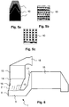
- the in Fig. 1 schematically illustrated section of the exhaust system according to the invention forms a reducing agent treatment line 1 for to be introduced into the exhaust system reducing agent.
- the reducing agent processing line 1 has a first cylindrical exhaust pipe section 2, which opens with its outlet-side open end 9 in a second cylindrical exhaust pipe section 3.
- the junction is arranged at an opening 8 in the cylinder jacket surface of the second exhaust pipe section 3.
- At the junction of the first exhaust pipe section 2 is connected with its open end 9 along its edge contour blunt and positive and materially connected to the edge contour of the opening 8 in the cylinder jacket surface of the second exhaust pipe section 3.
- both the cross section of the first exhaust pipe pipe section 2 and the cross section of the second exhaust pipe pipe section 3 at the confluence point have an oval or elliptical shape.
- the opening 8 has an oval or elliptical shape, wherein the longer axis of the elliptically shaped opening 8 is oriented parallel to the cylinder axis 12 of the second exhaust pipe section 3.
- the extending in the direction of the cylinder axis 12 of the second exhaust pipe section 3 longer extent a of the elliptical opening 8 and thus also the first exhaust pipe section 2 at the connection of the first exhaust pipe section 2 and second exhaust pipe section 3 is thus greater than the perpendicular thereto oriented transverse extent b.
- the ratio a / b is preferably in the range between 1.5 and 4.
- the shorter axis b of the elliptical opening 8 and the first exhaust pipe section 2 is oriented at the injection point at least approximately parallel to the larger cross-sectional axis d of the second elliptical exhaust pipe section 3.
- the shorter axis c of the elliptical cross-sectional area of the second exhaust pipe section 3 is therefore oriented at the point of entry parallel to the cylinder axis 11 of the first exhaust pipe section 2.
- the ratio d / c is of longer cross-sectional axis d and
- the shorter transverse dimension b of the opening 8 is preferably smaller than the shorter cross-sectional axis c of the second exhaust pipe pipe section 3.
- the shorter cross-sectional axis c is preferably selected in the range of 30 mm to 100 mm.
- Exhaust gas of an internal combustion engine flows from a in Fig. 1 also not shown exhaust gas purification unit, preferably an oxidation catalyst, in the first exhaust pipe section 2 and flows through the first exhaust pipe section 2.
- the at least approximately parallel to the cylinder axis 11 of the first exhaust pipe section 2 exhaust flow direction is shown by dashed arrows 5.
- the exhaust gas is enriched with a reducing agent, preferably a solution of a material capable of splitting off ammonia.
- a reducing agent preferably a solution of a material capable of splitting off ammonia.
- HWL aqueous urea solution
- the enrichment of the exhaust gas with HWL takes place by spraying by means of an injector 4, which is arranged close to the junction of the first exhaust pipe section 2 in the second Abgasieitungsrohrabites 3 at the first exhaust pipe section 2.
- the distance of the injector 4 to the junction of the exhaust pipe sections 2, 3 is preferably significantly less than the longer cross-sectional dimension a and more preferably less than the shorter cross-sectional dimension b of the first exhaust pipe section. 2
- Sprayed reducing agent meets, as shown by dotted arrows, acting as evaporator plates baffles 10, which are arranged above the opening 8 in the cylindrical surface of the second exhaust pipe section 3. Evaporated or rebounding from the evaporator plates liquid reducing agent is detected by the exhaust gas flow and entrained.
- Special features of the reducing agent injection and evaporation as well as the design, arrangement and function of the impact elements will be discussed in more detail below.
- Exhaust gas added with HWL then flows in a substantially vertical direction with respect to the cylinder axis 12 of the second exhaust pipe section 3 through the Opening 8 in this one.
- Exhaust gas flowing into the second exhaust pipe pipe section 3 is passed therethrough and flows out of an open end 7.
- an exhaust gas cleaning component not shown, preferably via an inlet funnel, connected to the second exhaust pipe pipe section 3.
- the exhaust gas purification component is preferably a catalytically and / or filter technically effective component.
- a housing is connected to the open end 7 of the second exhaust pipe section 3, in which a particulate filter is housed.
- the second exhaust pipe section 3 has a closed end 6.
- a flat closure lid can be welded. From the first exhaust pipe pipe section 2 through the opening 8 in the cylinder jacket surface of the second exhaust pipe pipe section 3 in this incoming exhaust gas is therefore deflected in its main flow direction by about 90 °. It is preferably provided that the upstream with respect to the deflected main flow direction of the exhaust gas upstream end of the opening 8 is adjacent to the closed end 6 or at least arranged close thereto. As a result, the formation of a flow dead zone at the closed end 6 of the second exhaust pipe section 3 is avoided.
- incoming exhaust gas strikes a region of the inner wall of the second exhaust pipe pipe section 3 opposite the opening 8 and is deflected.
- two oppositely rotating vortices as shown by the dashed arrows 5 '.
- the formation of two oppositely rotating exhaust vortex has proved to be very particularly advantageous in terms of the preparation of the reducing agent.
- a uniform distribution of liquid, where appropriate predominantly in the form of small droplets present reducing agent, and especially of already evaporated reducing agent is improved.
- the swirling significantly improves the evaporation of HWL.
- release of ammonia by thermolysis and / or hydrolysis is improved.
- the wetted pipe surface also acts as an evaporator surface, whereby the evaporation of the HWL is further improved.
- FIG. 2 a flow diagram, obtained from a computational flow simulation, shown.
- the flow pattern shows flow threads in a plan view of a section of the reducing agent preparation section 1 in the direction of the cylinder axis 12 of the second exhaust pipe section 3.
- two countercurrent revolutions approximately opposite a respective focal point of the elliptical cross-sectional area form in the second exhaust pipe section 3 decreasing diameter more and more approximate an ideal circular shape.
- the longer axis d of the elliptical cross-sectional area of the second exhaust pipe pipe section 3 is approximately twice as large as the shorter axis c.
- the shorter cross-sectional dimension b of the first exhaust pipe section 2 increases with increasing distance from the junction of the two exhaust pipe pipe sections 2, 3. In this way, a continuous transition to the larger dimensions of an optionally provided inlet funnel for a connected exhaust gas purification element can be achieved.
- this also applies to the other cross-sectional dimensions a, c and d.
- the cross-sectional dimensions of the exhaust pipe pipe sections 2, 3 are selected so that forms in conjunction with the prevailing exhaust gas mass flows in the second exhaust pipe section 3, a double vortex, which is at least approximately maintained along a length of more than 200 mm, preferably more than 300 mm.
- a maintenance of a double vortex is preferably provided until a downstream exhaust gas purification element or an exhaust gas inlet funnel provided therefor is reached.
- the cross-sectional dimensions are selected such that, at least in the region of the exhaust gas inlet in the second exhaust pipe pipe section 3 a swirl number of the exhaust gas of at least 0.3 each individual vortex is achieved.
- it may be provided to design the cross-sectional dimensions a, b, c, d of the exhaust pipe pipe sections 2, 3 as a function of the displacement of the internal combustion engine so that an inlet swirl number of at least 0.3 is achieved.
- a reducing agent processing line 1 of an exhaust system differs from the in Fig. 1 illustrated embodiment, essentially by a tangential exhaust gas supply from the first Abgasieitungsrohrabites 2 in the second exhaust pipe section 3.
- the first exhaust pipe section 2 is off-center with respect to the second exhaust pipe pipe section 3 attached.
- Exhaust gas flowing into the second exhaust pipe pipe section 3 is thus not directed to a central region of the cross-sectional area of the second exhaust pipe pipe section 3, but to a decentralized area.
- HWL enriched exhaust gas thus flows approximately tangentially with respect to the second exhaust pipe pipe section 3 in this.
- the second exhaust pipe section 3 has a circular cross-section in this embodiment, so instead of a double vortex as shown, a single vortex is formed.
- the diameter D of the second exhaust pipe pipe section 3 is preferably in the range of the cross-sectional dimensions c and d of in Fig. 1 illustrated elliptical embodiment. For typical car engine sizes, it is preferably in the range between 30 mm to 150 mm.
- the cross-sectional shape of the first exhaust pipe pipe section is chosen rectangular in the present case.
- the embodiment of Fig. 1 made dimension information and the information on the vorticity of the forming in the second exhaust pipe section 3 exhaust vortex.
- the longer side a of the cross section of the first exhaust pipe pipe section 2 at the connection point of the exhaust pipe pipe sections 2, 3 is preferably at least as large as the diameter D of the second exhaust pipe pipe section.
- the ratio a / D is particularly preferably chosen in the range from 1.5 to 3. It is understood that also in the embodiment of Fig. 1 a rectangular cross-section of the first exhaust pipe section may be provided.
- the present invention provides an evaporator device which is provided upstream of the connection point of the first exhaust pipe pipe section 2 and the second exhaust pipe pipe section 3. This is on Fig. 1 With reference to the explanations, which are equally applied to those in Fig. 4 illustrated embodiment of the reducing agent processing line 1 apply.
- the evaporator device has at least one, but preferably up to 8 impact elements 10.
- the impact elements 10 which also act as evaporator plates, are designed as planar sheets whose normal direction is oriented at least approximately perpendicularly to the cylinder axis 11 of the first exhaust pipe pipe section 2 and thus to the exhaust gas flow direction.
- the baffles 10 are arranged equidistant from each other. As a result of this flow-favorable orientation, no or at most a negligible flow resistance is caused by the impact elements 10.
- a downstream end of the baffles 10 is preferably in the plane of the opening 8 in the cylindrical surface of the second exhaust pipe section 3 or a few mm further offset from the exhaust gas flow direction.
- An upstream end of the baffle elements 10 is located substantially at the level of the injector unit 4 arranged on the first exhaust pipe pipe section 2.
- the injector unit 4 is arranged such that it can spray HWL approximately perpendicular to the cylinder axis 11. However, a slight inclination of the discharge direction in the exhaust gas flow direction may be provided.
- the HWL sprayed by the injector unit 4 thus strikes the baffle elements approximately perpendicularly, but at most at an acute angle with respect to the normal direction of the baffle elements.
- HWL droplets impinging on the baffle elements 10 rebound from them or wet their surface with a subsequent evaporation. Both processes support a distribution of HWL in the Exhaust.
- a rebound of droplets impinging on the baffles 10 occurs mainly when the baffles 10 are at a temperature above the Leidenfrost temperature. It has been shown that the size of rebounding droplets is reduced in comparison to impacting droplets and thus their distribution is improved.
- the further transport of the HWL-enriched exhaust gas is also a further impact of the droplets on the opening 8 in the second exhaust pipe section 3 opposite pipe inner wall. This is a repeated rebound with further droplet reduction or evaporation of another portion of the exhaust gas supplied HWL.
- the baffle elements are designed or arranged with respect to the discharge direction of the injector 4 that all baffles 10 and preferably also the injector unit 4 opposite inner wall of the first exhaust pipe section 2 at least partially be detected by the spray or spray cone and wetted.
- the baffle elements 10 offset from one another in the exhaust gas flow direction such that their upstream and / or downstream ends are increasingly displaced with respect to the exhaust gas flow direction with increasing distance of the baffle elements 10 from the injector unit 4. It can be provided with increasing distance from the injector 4, an increasing length of the baffles, ie an increasing extent of the baffles 10 in and / or opposite to the exhaust gas flow direction.
- FIG. 5a An example of such an advantageous staggering is in Fig. 5a shown schematically. It can, as in Fig. 5a it can be provided that the area size of the baffle elements 10 also increases with increasing distance of the baffle elements 10 from the injector unit 4. In this way, the proportion of the sprayed HWL, which impinges on the farther from the injector 4 more distant baffles 10, increases and thus improves the conditioning effect of this particular "rear" baffles 10. As in Fig. 5a 1, a width of the impact elements 10 which increases in or against the exhaust gas flow direction can also be provided at least in regions.
- FIG. 5b For example, a perforated embodiment is shown.
- Fig. 5c shows schematically a slotted shape. It is advantageous if the perforations of the baffle surface makes up about 5% to about 50% of the total gross area.
- a surface shaping of the baffles may be provided approximately in the form of nubs.
- a roughening and / or a coating may be provided. A preferred value for a surface roughness is in the range of 5 ⁇ m to 50 ⁇ m.
- a catalytic coating may be provided to aid in thermolysis and / or hydrolysis of urea. It is also possible to provide a coating which additionally or alternatively counteracts deposit formation with respect to deposition of urea decomposition products.
- the reducing agent treatment line 1 makes it possible, in particular by synergistic interaction of spraying and evaporation with subsequent flow direction deflection in conjunction with vortex formation, to provide extremely effective reducing agent treatment.
- HWL as a reducing agent
- an effective release of ammonia is achieved with a particularly good uniform distribution with short line lengths.
- the reducing agent treatment line 1 is characterized by a particularly low flow resistance.
- an additional installation element for mixing or swirl generation such as a static mixer before and especially after the HWL supply to the exhaust gas can be omitted.
- the illustrated as described and described reducing agent treatment line 1 therefore allows a particularly compact design of the exhaust system according to the invention, even with complex structure.
- a compact exhaust aftertreatment system in which two housings 13, 18 for exhaust aftertreatment components are connected to one another via the reducing agent treatment line 1.
- an oxidation catalyst is presently arranged in an upstream housing 13 in an upstream housing 13.
- a particle filter is arranged one behind the other and an SCR catalytic converter is arranged at a slight distance therefrom, wherein the particle filter is preferably provided with an SCR catalyst coating.
- An exhaust gas inlet funnel 15 of the upstream housing 13 receives exhaust gas of a diesel engine, not shown, and is for this purpose preferably connected to an exhaust gas turbocharger outlet, also not shown.
- Exhaust gas treated by the oxidation catalyst is supplied from the housing 13 via a housing outlet funnel 14 to the first exhaust pipe pipe section 2 of the reducing agent preparation section 1.
- the first exhaust pipe section 2 is by means of a in Fig. 6 injector unit, not shown, which is provided at a port 16, HWL injected into the exhaust.
- the supply of urea-containing or ammonia-containing exhaust gas to the housing 18 can be made particularly short.
- the described exhaust deflection by about 90 ° at the transition of the first exhaust pipe section 2 to the second exhaust pipe section 3 allows a particularly compact design of the exhaust aftertreatment system. Heat and pressure losses are minimized, which enables a particularly efficient exhaust gas purification.
- an embodiment of the exhaust system according to the invention has proven in which, as in Fig. 6 illustrated, the upstream housing 13 is oriented at least approximately vertically and the immediately downstream and connected via the reducing agent processing line 1 to the housing 13 downstream housing 18 is arranged at least approximately horizontally oriented.
- an arrangement is particularly compact and space-saving, in which the downstream housing 18 is at least partially disposed in the same geodetic height as the upstream housing 13. It is particularly preferred if the central axis of the housing 18 is arranged geodetically at least approximately as high or even higher than the downstream end of the housing 13.
Landscapes
- Chemical & Material Sciences (AREA)
- Engineering & Computer Science (AREA)
- Chemical Kinetics & Catalysis (AREA)
- Health & Medical Sciences (AREA)
- Toxicology (AREA)
- Combustion & Propulsion (AREA)
- Mechanical Engineering (AREA)
- General Engineering & Computer Science (AREA)
- Exhaust Gas After Treatment (AREA)
Claims (13)
- Système d'échappement d'un moteur à combustion interne qui, pour guider le gaz d'échappement, présente une première partie cylindrique (2) de conduite d'échappement et une seconde partie cylindrique (3) de conduite d'échappement,- est disposée sur la première partie (2) de conduite d'échappement, une unité d'injecteur (4) servant à introduire un moyen réducteur dans le gaz d'échappement s'écoulant à travers la première partie (2) de conduite d'échappement,- la seconde partie (3) de conduite d'échappement présentant une surface externe de cylindre, une première extrémité fermée (6) et une seconde extrémité ouverte (7) ainsi qu'un orifice dans la surface externe de cylindre adjacente à l'extrémité fermée (6),- une extrémité ouverte (6) de la première partie (2) de conduite d'échappement étant reliée par complémentarité de forme à la seconde partie (3) de conduite d'échappement de sorte que le gaz d'échappement s'écoulant à partir de l'extrémité ouverte (9) de la première partie (2) de conduite d'échappement dans au moins un sens approximativement vertical à l'étendue longitudinale de la seconde partie (3) de conduite d'échappement puisse s'écouler par l'orifice (8) dans la surface externe de cylindre de la seconde partie (3) de conduite d'échappement dans la seconde partie (3) de conduite d'échappement, caractérisé en ce que- la dilatation (a) de la première partie (2) de conduite d'échappement est supérieure entre 1,5 et 4 fois à la dilatation transversale orientée verticalement à celle-ci,- un axe (11) de cylindre de la première partie (2) de conduite d'échappement dans la zone du point de raccordement avec la seconde partie (3) de conduite d'échappement est orienté dans une zone centrale d'une surface de section transversale de la seconde partie (3) de conduite d'échappement, et- d'un dispositif évaporateur (10) disposé dans la première partie (2) de conduite d'échappement.
- Système d'échappement selon la revendication 1, caractérisé en ce que l'unité d'injecteur (4) est disposé à une distance en amont du point de raccordement de la première partie (2) de conduite d'échappement avec la seconde parte (3) de conduite d'échappement qui est inférieure à un diamètre de la première partie (2) de conduite d'échappement ou de la seconde partie (3) d'échappement.
- Système d'échappement selon la revendication 1 ou la revendication 2, caractérisé en ce que le dispositif évaporateur (10) est disposé à une distance en amont du point de raccordement de la première partie (2) de conduite d'échappement avec la seconde partie (3) de conduite d'échappement qui est inférieure à un diamètre de la première partie (2) de conduite d'échappement ou de la seconde partie (3) de conduite d'échappement et présente au moins un élément d'impact tabulaire sur lequel l'agent réducteur introduit dans la première partie (2) de conduite d'échappement est injecté au moyen de l'unité d'injecteur (4).
- Système d'échappement selon la revendication 3, caractérisé en ce que l'au moins un élément d'impact est disposé directement au-dessus de l'orifice (8) ou devant celui-ci sur la surface externe de cylindre de la seconde partie (3) de conduite d'échappement.
- Système d'échappement selon la revendication 3 ou la revendication 4, caractérisé en ce que l'au moins un élément d'impact est de forme approximativement plate, une normale à une surface du plan d'élément d'impact est orienté au moins approximativement verticalement à la direction d'écoulement des gaz d'échappement.
- Système d'échappement selon l'une quelconque des revendications 3 à 5, caractérisé en ce qu'il est prévu une pluralité d'éléments d'impact.
- Système d'échappement selon la revendication 6, caractérisé en ce qu'une dilatation des éléments d'impact est différentiée par la surface.
- Système d'échappement selon la revendication 1 à 7, caractérisé en ce que la seconde partie (3) de conduite d'échappement présente dans la zone de l'orifice (8) sur la surface externe de cylindre une forme de section transversale ovale.
- Procédé de traitement d'un agent réducteur introduit dans une première partie (2) de conduite d'échappement d'un système d'échappement d'un moteur à combustion interne selon la revendication 1 à 8, selon lequel l'agent réducteur introduit s'évapore au moins partiellement dans un dispositif évaporateur disposé dans la première partie (2) de conduite d'échappement et ensuite s'écoule conjointement avec le gaz d'échappement du moteur à combustion interne dans une direction à travers l'orifice (8) sur une surface externe de cylindre d'une seconde partie (3) de conduite d'échappement, qui est orientée au moins approximativement verticalement à une direction axiale de la seconde partie (3) de conduite d'échappement, le gaz d'échappement s'écoulant dans la seconde partie (3) de conduite d'échappement formant deux tourbillons tournant en sens contrainte lorsqu'ils sont observés par rapport à une direction axiale de la seconde partie (3) de conduite d'échappement.
- Procédé selon la revendication 9, caractérisé en ce que pour les deux tourbillons au moins dans la zone d'écoulement de gaz d'échappement dans la seconde partie (3) de conduite d'échappement on atteint un nombre de tourbillons longitudinaux des gaz d'échappement d'au moins 0,3.
- Procédé selon la revendication 9 ou la revendication 10, caractérisé en ce qu'en tant que dispositif évaporateur (10) il est prévu une pluralité de plaques (40) d'évaporateur et en ce que l'agent réducteur est pulvérisé dans la première partie (2) de conduite d'échappement de telle sorte qu'il soit injecté sur l'ensemble des plaques d'évaporateur.
- Procédé selon la revendication 11, caractérisé en ce que l'agent réducteur est injecté dans un angle aigue au plus par rapport à une direction de normale des plaques d'évaporateur dans la première partie (2) de conduite d'échappement.
- Procédé selon la revendication 9 ou la revendication10, caractérisé en ce que l'agent réducteur est injecté au moins approximativement verticalement par rapport à un écoulement de gaz d'échappement dans la première partie (2) de conduite d'échappement.
Applications Claiming Priority (2)
| Application Number | Priority Date | Filing Date | Title |
|---|---|---|---|
| DE102012000597A DE102012000597A1 (de) | 2012-01-14 | 2012-01-14 | Abgassystem einer Brennkraftmaschine und Verfahren zur Aufbereitung eines in Brennkraftmaschinenabgas eingebrachten Reduktionsmittels |
| PCT/EP2013/000067 WO2013104544A2 (fr) | 2012-01-14 | 2013-01-11 | Système d'échappement d'un moteur à combustion interne et procédé de préparation d'un agent réducteur introduit dans les gaz d'échappement dudit moteur |
Publications (2)
| Publication Number | Publication Date |
|---|---|
| EP2802753A2 EP2802753A2 (fr) | 2014-11-19 |
| EP2802753B1 true EP2802753B1 (fr) | 2017-04-05 |
Family
ID=47605459
Family Applications (1)
| Application Number | Title | Priority Date | Filing Date |
|---|---|---|---|
| EP13701361.1A Active EP2802753B1 (fr) | 2012-01-14 | 2013-01-11 | Système d'échappement d'un moteur à combustion interne et procédé de préparation d'un agent réducteur introduit dans les gaz d'échappement dudit moteur |
Country Status (6)
| Country | Link |
|---|---|
| US (1) | US9157358B2 (fr) |
| EP (1) | EP2802753B1 (fr) |
| JP (1) | JP5866031B2 (fr) |
| CN (1) | CN104053878B (fr) |
| DE (1) | DE102012000597A1 (fr) |
| WO (1) | WO2013104544A2 (fr) |
Families Citing this family (19)
| Publication number | Priority date | Publication date | Assignee | Title |
|---|---|---|---|---|
| DE202013006962U1 (de) | 2013-08-05 | 2013-08-28 | Tenneco Gmbh | Mischkammer |
| US9470132B2 (en) * | 2014-12-05 | 2016-10-18 | Cummins Emission Solutions, Inc. | Compact radial exterior exhaust assisted decomposition reactor pipe |
| DE102015103425B3 (de) | 2015-03-09 | 2016-05-19 | Tenneco Gmbh | Mischvorrichtung |
| JP6498993B2 (ja) * | 2015-04-01 | 2019-04-10 | 日野自動車株式会社 | 排気浄化装置 |
| WO2017054179A1 (fr) * | 2015-09-30 | 2017-04-06 | Robert Bosch Gmbh | Système et boîte de post-traitement des gaz d'échappement du type à mélange par tourbillon |
| DE102016200328A1 (de) * | 2016-01-14 | 2017-07-20 | Bayerische Motoren Werke Aktiengesellschaft | System zum Nachbehandeln eines Abgases und Kraftfahrzeug |
| DE102016101055A1 (de) * | 2016-01-21 | 2017-07-27 | Benteler Automobiltechnik Gmbh | SCR-Abgasnachbehandlungsanordnung |
| DE102016108113B4 (de) * | 2016-05-02 | 2024-04-25 | Friedrich Boysen Gmbh & Co. Kg | Vorrichtung zum Einbringen und Verteilen einer Flüssigkeit in einen Gasstrom |
| DE102016213417A1 (de) | 2016-07-22 | 2018-01-25 | Robert Bosch Gmbh | Vorrichtung zum Vermischen |
| DE102016217750A1 (de) * | 2016-09-16 | 2018-03-22 | Continental Automotive Gmbh | Abgasnachbehandlungseinheit |
| DE102016223578A1 (de) | 2016-11-28 | 2018-05-30 | Continental Automotive Gmbh | Vorrichtung zur Verdampfung eines Fluids |
| DE102017100132A1 (de) | 2017-01-05 | 2018-07-05 | Eberspächer Exhaust Technology GmbH & Co. KG | Abgasanlage |
| KR102089126B1 (ko) * | 2017-05-24 | 2020-03-13 | 주식회사 엘지화학 | 선택적 촉매 환원 시스템 |
| FR3068730B1 (fr) * | 2017-07-04 | 2020-02-14 | Faurecia Systemes D'echappement | Dispositif d'injection pour une ligne d'echappement de vehicule et ligne d'echappement correspondante |
| US11230954B2 (en) * | 2017-07-19 | 2022-01-25 | Cummins Emission Solutions Inc. | Deposit reduction using interior surface finishing |
| WO2019042528A1 (fr) | 2017-08-29 | 2019-03-07 | Robert Bosch Gmbh | Dispositif de mélange |
| CN110953045A (zh) * | 2019-12-10 | 2020-04-03 | 苏州国方汽车电子有限公司 | 用于船机排气后处理系统的混合器组件 |
| JP7252182B2 (ja) * | 2020-09-08 | 2023-04-04 | 株式会社三井E&Sマシナリー | 尿素気化装置 |
| JP7250742B2 (ja) * | 2020-09-28 | 2023-04-03 | 株式会社三井E&Sマシナリー | 脱硝部の閉塞防止装置 |
Family Cites Families (14)
| Publication number | Priority date | Publication date | Assignee | Title |
|---|---|---|---|---|
| RU2349767C2 (ru) * | 2002-07-25 | 2009-03-20 | Рифаат А. КЭММЕЛ | Система и способ дополнительной обработки выхлопных газов |
| JP2008014213A (ja) * | 2006-07-05 | 2008-01-24 | Hitachi Ltd | 排気処理装置 |
| DE102006043225A1 (de) * | 2006-09-11 | 2008-03-27 | J. Eberspächer GmbH & Co. KG | Abgasanlage für eine Brennkraftmaschine |
| US7748212B2 (en) * | 2007-03-09 | 2010-07-06 | Cummins Filtration Ip, Inc. | Exhaust aftertreatment system with flow distribution |
| JP2008267225A (ja) * | 2007-04-18 | 2008-11-06 | Futaba Industrial Co Ltd | 排気浄化装置 |
| JP5173308B2 (ja) * | 2007-07-31 | 2013-04-03 | 日野自動車株式会社 | 排気浄化装置 |
| DE102007052262B4 (de) * | 2007-11-02 | 2023-11-02 | Bayerische Motoren Werke Aktiengesellschaft | Einrichtung zum Mischen und/oder Verdampfen eines Reduktionsmittels sowie Einrichtung zur Beaufschlagung eines Abgasstroms mit einem Reduktionsmittel |
| JP4951560B2 (ja) * | 2008-03-19 | 2012-06-13 | 東京濾器株式会社 | 内燃機関用の排ガス浄化装置 |
| JP5308176B2 (ja) * | 2009-02-03 | 2013-10-09 | ヤンマー株式会社 | 排気浄化装置 |
| DE102009041345A1 (de) * | 2009-09-15 | 2011-04-21 | Mtu Friedrichshafen Gmbh | System zur Einbringung eines fluiden Zusatzstoffes |
| US8713914B2 (en) * | 2009-09-29 | 2014-05-06 | GM Global Technology Operations LLC | Method and apparatus for monitoring a hydrocarbon-selective catalytic reduction device |
| JP5534925B2 (ja) * | 2010-04-30 | 2014-07-02 | ヤンマー株式会社 | 内燃機関の排気浄化システム |
| CN102042063A (zh) * | 2010-09-30 | 2011-05-04 | 中国人民解放军军事交通学院 | 一种用于柴油机尾气氮氧化物净化还原剂的雾化喷射装置 |
| US8635858B2 (en) * | 2011-10-25 | 2014-01-28 | Ford Global Technologies, Llc | Fluid-spray atomizer |
-
2012
- 2012-01-14 DE DE102012000597A patent/DE102012000597A1/de not_active Withdrawn
-
2013
- 2013-01-11 CN CN201380005429.3A patent/CN104053878B/zh active Active
- 2013-01-11 US US14/371,914 patent/US9157358B2/en active Active
- 2013-01-11 EP EP13701361.1A patent/EP2802753B1/fr active Active
- 2013-01-11 WO PCT/EP2013/000067 patent/WO2013104544A2/fr active Application Filing
- 2013-01-11 JP JP2014551572A patent/JP5866031B2/ja active Active
Also Published As
| Publication number | Publication date |
|---|---|
| US20150047324A1 (en) | 2015-02-19 |
| CN104053878B (zh) | 2017-07-25 |
| WO2013104544A2 (fr) | 2013-07-18 |
| JP2015508469A (ja) | 2015-03-19 |
| WO2013104544A3 (fr) | 2013-09-26 |
| JP5866031B2 (ja) | 2016-02-17 |
| DE102012000597A1 (de) | 2013-07-18 |
| EP2802753A2 (fr) | 2014-11-19 |
| US9157358B2 (en) | 2015-10-13 |
| CN104053878A (zh) | 2014-09-17 |
Similar Documents
| Publication | Publication Date | Title |
|---|---|---|
| EP2802753B1 (fr) | Système d'échappement d'un moteur à combustion interne et procédé de préparation d'un agent réducteur introduit dans les gaz d'échappement dudit moteur | |
| EP2912287B1 (fr) | Système de gaz d'échappement | |
| EP2820260B1 (fr) | Dispositif d'épuration de gaz d'échappement | |
| EP2700442B1 (fr) | Installation de gaz d'échappement avec dispositif de mélange et/ou d'évaporation | |
| EP2855868B2 (fr) | Système d'addition et de préparation d'agent de réduction pour véhicule automobile | |
| EP1404949B1 (fr) | Dispositif de melange destine a un systeme d'epuration de gaz d'echappement | |
| DE112010002589B4 (de) | Abgasstrang mit Einspritzsystem | |
| DE102007021598B4 (de) | Vorrichtung zum Verteilen von fließfähigen Zusatzstoffen in Abgasanlagen | |
| DE102011111765B4 (de) | Mischereinrichtung | |
| DE102013005206B3 (de) | Einströmkammer für einen Katalysator einer Abgasreinigungsanlage | |
| EP2921220B1 (fr) | Mélangeur pour une installation de gaz d'échappement | |
| EP2594330B1 (fr) | Dispositif de mélange et/ou d'évaporation | |
| DE102016222743A1 (de) | Integriertes Abgasnachbehandlungssystem | |
| WO2013010700A1 (fr) | Agencement permettant d'introduire un additif dans un flux de gaz | |
| DE102008017395C5 (de) | Misch- und/oder Verdampfungseinrichtung | |
| EP2956639B1 (fr) | Partie de conduite des gaz d'échappement permettant d'amener un additif liquide | |
| EP3797221B1 (fr) | Dispositif pour alimenter un réactif chimique dans le système d'échappement d'un moteur à combustion interne | |
| DE102012014528A1 (de) | Mehrstufiger Plattenmischer | |
| DE102016014966B4 (de) | Abgasnachbehandlungseinrichtung für einen Kraftwagen | |
| DE102015217357A1 (de) | Mischvorrichtung und Mischersystem für eine Abgasanlage eines Verbrennungsmotors | |
| WO2013060598A1 (fr) | Ensemble mélangeur pour la préparation d'agents de réduction | |
| EP4130446B1 (fr) | Dispositif de mélange | |
| DE102008028171A1 (de) | Düseneinrichtung und Verfahren zum Zuführen eines Hilfsmittels in einen Abgasstrom einer Verbrennungskraftmaschine | |
| EP2823878B1 (fr) | Mélangeur à plaques à plusieurs étages | |
| EP4234073A1 (fr) | Dispositif pour mélanger un additif avec un courant gazeux |
Legal Events
| Date | Code | Title | Description |
|---|---|---|---|
| PUAI | Public reference made under article 153(3) epc to a published international application that has entered the european phase |
Free format text: ORIGINAL CODE: 0009012 |
|
| 17P | Request for examination filed |
Effective date: 20140507 |
|
| AK | Designated contracting states |
Kind code of ref document: A2 Designated state(s): AL AT BE BG CH CY CZ DE DK EE ES FI FR GB GR HR HU IE IS IT LI LT LU LV MC MK MT NL NO PL PT RO RS SE SI SK SM TR |
|
| DAX | Request for extension of the european patent (deleted) | ||
| 17Q | First examination report despatched |
Effective date: 20160204 |
|
| REG | Reference to a national code |
Ref country code: DE Ref legal event code: R079 Ref document number: 502013006870 Country of ref document: DE Free format text: PREVIOUS MAIN CLASS: F01N0003200000 Ipc: F01N0003280000 |
|
| GRAP | Despatch of communication of intention to grant a patent |
Free format text: ORIGINAL CODE: EPIDOSNIGR1 |
|
| GRAJ | Information related to disapproval of communication of intention to grant by the applicant or resumption of examination proceedings by the epo deleted |
Free format text: ORIGINAL CODE: EPIDOSDIGR1 |
|
| RIC1 | Information provided on ipc code assigned before grant |
Ipc: F01N 3/28 20060101AFI20160912BHEP Ipc: F01N 3/20 20060101ALI20160912BHEP |
|
| GRAP | Despatch of communication of intention to grant a patent |
Free format text: ORIGINAL CODE: EPIDOSNIGR1 |
|
| INTG | Intention to grant announced |
Effective date: 20160926 |
|
| INTG | Intention to grant announced |
Effective date: 20161026 |
|
| GRAS | Grant fee paid |
Free format text: ORIGINAL CODE: EPIDOSNIGR3 |
|
| GRAA | (expected) grant |
Free format text: ORIGINAL CODE: 0009210 |
|
| AK | Designated contracting states |
Kind code of ref document: B1 Designated state(s): AL AT BE BG CH CY CZ DE DK EE ES FI FR GB GR HR HU IE IS IT LI LT LU LV MC MK MT NL NO PL PT RO RS SE SI SK SM TR |
|
| REG | Reference to a national code |
Ref country code: GB Ref legal event code: FG4D Free format text: NOT ENGLISH |
|
| REG | Reference to a national code |
Ref country code: CH Ref legal event code: EP |
|
| REG | Reference to a national code |
Ref country code: AT Ref legal event code: REF Ref document number: 882063 Country of ref document: AT Kind code of ref document: T Effective date: 20170415 |
|
| REG | Reference to a national code |
Ref country code: IE Ref legal event code: FG4D Free format text: LANGUAGE OF EP DOCUMENT: GERMAN |
|
| REG | Reference to a national code |
Ref country code: DE Ref legal event code: R096 Ref document number: 502013006870 Country of ref document: DE |
|
| REG | Reference to a national code |
Ref country code: NL Ref legal event code: MP Effective date: 20170405 |
|
| REG | Reference to a national code |
Ref country code: LT Ref legal event code: MG4D |
|
| PG25 | Lapsed in a contracting state [announced via postgrant information from national office to epo] |
Ref country code: NL Free format text: LAPSE BECAUSE OF FAILURE TO SUBMIT A TRANSLATION OF THE DESCRIPTION OR TO PAY THE FEE WITHIN THE PRESCRIBED TIME-LIMIT Effective date: 20170405 |
|
| PG25 | Lapsed in a contracting state [announced via postgrant information from national office to epo] |
Ref country code: HR Free format text: LAPSE BECAUSE OF FAILURE TO SUBMIT A TRANSLATION OF THE DESCRIPTION OR TO PAY THE FEE WITHIN THE PRESCRIBED TIME-LIMIT Effective date: 20170405 Ref country code: LT Free format text: LAPSE BECAUSE OF FAILURE TO SUBMIT A TRANSLATION OF THE DESCRIPTION OR TO PAY THE FEE WITHIN THE PRESCRIBED TIME-LIMIT Effective date: 20170405 Ref country code: ES Free format text: LAPSE BECAUSE OF FAILURE TO SUBMIT A TRANSLATION OF THE DESCRIPTION OR TO PAY THE FEE WITHIN THE PRESCRIBED TIME-LIMIT Effective date: 20170405 Ref country code: NO Free format text: LAPSE BECAUSE OF FAILURE TO SUBMIT A TRANSLATION OF THE DESCRIPTION OR TO PAY THE FEE WITHIN THE PRESCRIBED TIME-LIMIT Effective date: 20170705 Ref country code: FI Free format text: LAPSE BECAUSE OF FAILURE TO SUBMIT A TRANSLATION OF THE DESCRIPTION OR TO PAY THE FEE WITHIN THE PRESCRIBED TIME-LIMIT Effective date: 20170405 Ref country code: GR Free format text: LAPSE BECAUSE OF FAILURE TO SUBMIT A TRANSLATION OF THE DESCRIPTION OR TO PAY THE FEE WITHIN THE PRESCRIBED TIME-LIMIT Effective date: 20170706 |
|
| PG25 | Lapsed in a contracting state [announced via postgrant information from national office to epo] |
Ref country code: RS Free format text: LAPSE BECAUSE OF FAILURE TO SUBMIT A TRANSLATION OF THE DESCRIPTION OR TO PAY THE FEE WITHIN THE PRESCRIBED TIME-LIMIT Effective date: 20170405 Ref country code: BG Free format text: LAPSE BECAUSE OF FAILURE TO SUBMIT A TRANSLATION OF THE DESCRIPTION OR TO PAY THE FEE WITHIN THE PRESCRIBED TIME-LIMIT Effective date: 20170705 Ref country code: LV Free format text: LAPSE BECAUSE OF FAILURE TO SUBMIT A TRANSLATION OF THE DESCRIPTION OR TO PAY THE FEE WITHIN THE PRESCRIBED TIME-LIMIT Effective date: 20170405 Ref country code: IS Free format text: LAPSE BECAUSE OF FAILURE TO SUBMIT A TRANSLATION OF THE DESCRIPTION OR TO PAY THE FEE WITHIN THE PRESCRIBED TIME-LIMIT Effective date: 20170805 Ref country code: SE Free format text: LAPSE BECAUSE OF FAILURE TO SUBMIT A TRANSLATION OF THE DESCRIPTION OR TO PAY THE FEE WITHIN THE PRESCRIBED TIME-LIMIT Effective date: 20170405 Ref country code: PL Free format text: LAPSE BECAUSE OF FAILURE TO SUBMIT A TRANSLATION OF THE DESCRIPTION OR TO PAY THE FEE WITHIN THE PRESCRIBED TIME-LIMIT Effective date: 20170405 |
|
| REG | Reference to a national code |
Ref country code: DE Ref legal event code: R097 Ref document number: 502013006870 Country of ref document: DE |
|
| REG | Reference to a national code |
Ref country code: FR Ref legal event code: PLFP Year of fee payment: 6 |
|
| PG25 | Lapsed in a contracting state [announced via postgrant information from national office to epo] |
Ref country code: CZ Free format text: LAPSE BECAUSE OF FAILURE TO SUBMIT A TRANSLATION OF THE DESCRIPTION OR TO PAY THE FEE WITHIN THE PRESCRIBED TIME-LIMIT Effective date: 20170405 Ref country code: SK Free format text: LAPSE BECAUSE OF FAILURE TO SUBMIT A TRANSLATION OF THE DESCRIPTION OR TO PAY THE FEE WITHIN THE PRESCRIBED TIME-LIMIT Effective date: 20170405 Ref country code: DK Free format text: LAPSE BECAUSE OF FAILURE TO SUBMIT A TRANSLATION OF THE DESCRIPTION OR TO PAY THE FEE WITHIN THE PRESCRIBED TIME-LIMIT Effective date: 20170405 Ref country code: RO Free format text: LAPSE BECAUSE OF FAILURE TO SUBMIT A TRANSLATION OF THE DESCRIPTION OR TO PAY THE FEE WITHIN THE PRESCRIBED TIME-LIMIT Effective date: 20170405 Ref country code: EE Free format text: LAPSE BECAUSE OF FAILURE TO SUBMIT A TRANSLATION OF THE DESCRIPTION OR TO PAY THE FEE WITHIN THE PRESCRIBED TIME-LIMIT Effective date: 20170405 |
|
| PLBE | No opposition filed within time limit |
Free format text: ORIGINAL CODE: 0009261 |
|
| STAA | Information on the status of an ep patent application or granted ep patent |
Free format text: STATUS: NO OPPOSITION FILED WITHIN TIME LIMIT |
|
| PG25 | Lapsed in a contracting state [announced via postgrant information from national office to epo] |
Ref country code: IT Free format text: LAPSE BECAUSE OF FAILURE TO SUBMIT A TRANSLATION OF THE DESCRIPTION OR TO PAY THE FEE WITHIN THE PRESCRIBED TIME-LIMIT Effective date: 20170405 Ref country code: SM Free format text: LAPSE BECAUSE OF FAILURE TO SUBMIT A TRANSLATION OF THE DESCRIPTION OR TO PAY THE FEE WITHIN THE PRESCRIBED TIME-LIMIT Effective date: 20170405 |
|
| 26N | No opposition filed |
Effective date: 20180108 |
|
| PG25 | Lapsed in a contracting state [announced via postgrant information from national office to epo] |
Ref country code: SI Free format text: LAPSE BECAUSE OF FAILURE TO SUBMIT A TRANSLATION OF THE DESCRIPTION OR TO PAY THE FEE WITHIN THE PRESCRIBED TIME-LIMIT Effective date: 20170405 |
|
| REG | Reference to a national code |
Ref country code: CH Ref legal event code: PL |
|
| PG25 | Lapsed in a contracting state [announced via postgrant information from national office to epo] |
Ref country code: MT Free format text: LAPSE BECAUSE OF FAILURE TO SUBMIT A TRANSLATION OF THE DESCRIPTION OR TO PAY THE FEE WITHIN THE PRESCRIBED TIME-LIMIT Effective date: 20170405 |
|
| PG25 | Lapsed in a contracting state [announced via postgrant information from national office to epo] |
Ref country code: LU Free format text: LAPSE BECAUSE OF NON-PAYMENT OF DUE FEES Effective date: 20180111 |
|
| REG | Reference to a national code |
Ref country code: IE Ref legal event code: MM4A |
|
| REG | Reference to a national code |
Ref country code: BE Ref legal event code: MM Effective date: 20180131 |
|
| PG25 | Lapsed in a contracting state [announced via postgrant information from national office to epo] |
Ref country code: LI Free format text: LAPSE BECAUSE OF NON-PAYMENT OF DUE FEES Effective date: 20180131 Ref country code: BE Free format text: LAPSE BECAUSE OF NON-PAYMENT OF DUE FEES Effective date: 20180131 Ref country code: CH Free format text: LAPSE BECAUSE OF NON-PAYMENT OF DUE FEES Effective date: 20180131 |
|
| PG25 | Lapsed in a contracting state [announced via postgrant information from national office to epo] |
Ref country code: IE Free format text: LAPSE BECAUSE OF NON-PAYMENT OF DUE FEES Effective date: 20180111 |
|
| REG | Reference to a national code |
Ref country code: AT Ref legal event code: MM01 Ref document number: 882063 Country of ref document: AT Kind code of ref document: T Effective date: 20180111 |
|
| PG25 | Lapsed in a contracting state [announced via postgrant information from national office to epo] |
Ref country code: AT Free format text: LAPSE BECAUSE OF NON-PAYMENT OF DUE FEES Effective date: 20180111 |
|
| PGFP | Annual fee paid to national office [announced via postgrant information from national office to epo] |
Ref country code: FR Payment date: 20190130 Year of fee payment: 7 Ref country code: GB Payment date: 20190130 Year of fee payment: 7 |
|
| PG25 | Lapsed in a contracting state [announced via postgrant information from national office to epo] |
Ref country code: MC Free format text: LAPSE BECAUSE OF FAILURE TO SUBMIT A TRANSLATION OF THE DESCRIPTION OR TO PAY THE FEE WITHIN THE PRESCRIBED TIME-LIMIT Effective date: 20170405 |
|
| PG25 | Lapsed in a contracting state [announced via postgrant information from national office to epo] |
Ref country code: TR Free format text: LAPSE BECAUSE OF FAILURE TO SUBMIT A TRANSLATION OF THE DESCRIPTION OR TO PAY THE FEE WITHIN THE PRESCRIBED TIME-LIMIT Effective date: 20170405 |
|
| PG25 | Lapsed in a contracting state [announced via postgrant information from national office to epo] |
Ref country code: HU Free format text: LAPSE BECAUSE OF FAILURE TO SUBMIT A TRANSLATION OF THE DESCRIPTION OR TO PAY THE FEE WITHIN THE PRESCRIBED TIME-LIMIT; INVALID AB INITIO Effective date: 20130111 Ref country code: PT Free format text: LAPSE BECAUSE OF FAILURE TO SUBMIT A TRANSLATION OF THE DESCRIPTION OR TO PAY THE FEE WITHIN THE PRESCRIBED TIME-LIMIT Effective date: 20170405 |
|
| PG25 | Lapsed in a contracting state [announced via postgrant information from national office to epo] |
Ref country code: MK Free format text: LAPSE BECAUSE OF NON-PAYMENT OF DUE FEES Effective date: 20170405 Ref country code: CY Free format text: LAPSE BECAUSE OF FAILURE TO SUBMIT A TRANSLATION OF THE DESCRIPTION OR TO PAY THE FEE WITHIN THE PRESCRIBED TIME-LIMIT Effective date: 20170405 |
|
| PG25 | Lapsed in a contracting state [announced via postgrant information from national office to epo] |
Ref country code: AL Free format text: LAPSE BECAUSE OF FAILURE TO SUBMIT A TRANSLATION OF THE DESCRIPTION OR TO PAY THE FEE WITHIN THE PRESCRIBED TIME-LIMIT Effective date: 20170405 |
|
| GBPC | Gb: european patent ceased through non-payment of renewal fee |
Effective date: 20200111 |
|
| REG | Reference to a national code |
Ref country code: DE Ref legal event code: R081 Ref document number: 502013006870 Country of ref document: DE Owner name: MERCEDES-BENZ GROUP AG, DE Free format text: FORMER OWNER: DAIMLER AG, 70327 STUTTGART, DE Ref country code: DE Ref legal event code: R082 Ref document number: 502013006870 Country of ref document: DE Representative=s name: JENSEN & SON, GB Ref country code: DE Ref legal event code: R081 Ref document number: 502013006870 Country of ref document: DE Owner name: DAIMLER AG, DE Free format text: FORMER OWNER: DAIMLER AG, 70327 STUTTGART, DE Ref country code: DE Ref legal event code: R082 Ref document number: 502013006870 Country of ref document: DE Representative=s name: JENSENS IP LIMITED, IE |
|
| PG25 | Lapsed in a contracting state [announced via postgrant information from national office to epo] |
Ref country code: GB Free format text: LAPSE BECAUSE OF NON-PAYMENT OF DUE FEES Effective date: 20200111 Ref country code: FR Free format text: LAPSE BECAUSE OF NON-PAYMENT OF DUE FEES Effective date: 20200131 |
|
| REG | Reference to a national code |
Ref country code: DE Ref legal event code: R082 Ref document number: 502013006870 Country of ref document: DE Representative=s name: JENSENS IP LIMITED, IE |
|
| REG | Reference to a national code |
Ref country code: DE Ref legal event code: R081 Ref document number: 502013006870 Country of ref document: DE Owner name: MERCEDES-BENZ GROUP AG, DE Free format text: FORMER OWNER: DAIMLER AG, STUTTGART, DE Ref country code: DE Ref legal event code: R082 Ref document number: 502013006870 Country of ref document: DE |
|
| PGFP | Annual fee paid to national office [announced via postgrant information from national office to epo] |
Ref country code: DE Payment date: 20240129 Year of fee payment: 12 |