EP2802753B1 - Exhaust gas system of an internal combustion engine, and method for preparing a reducing agent which is introduced into the internal combustion engine exhaust gas - Google Patents
Exhaust gas system of an internal combustion engine, and method for preparing a reducing agent which is introduced into the internal combustion engine exhaust gas Download PDFInfo
- Publication number
- EP2802753B1 EP2802753B1 EP13701361.1A EP13701361A EP2802753B1 EP 2802753 B1 EP2802753 B1 EP 2802753B1 EP 13701361 A EP13701361 A EP 13701361A EP 2802753 B1 EP2802753 B1 EP 2802753B1
- Authority
- EP
- European Patent Office
- Prior art keywords
- pipe section
- exhaust pipe
- exhaust
- reducing agent
- exhaust gas
- Prior art date
- Legal status (The legal status is an assumption and is not a legal conclusion. Google has not performed a legal analysis and makes no representation as to the accuracy of the status listed.)
- Active
Links
- 239000003638 chemical reducing agent Substances 0.000 title claims description 85
- 238000002485 combustion reaction Methods 0.000 title claims description 15
- 238000000034 method Methods 0.000 title claims description 15
- 238000011144 upstream manufacturing Methods 0.000 claims description 14
- 230000001154 acute effect Effects 0.000 claims description 3
- 239000007789 gas Substances 0.000 description 83
- 230000008020 evaporation Effects 0.000 description 19
- 238000001704 evaporation Methods 0.000 description 19
- 238000002360 preparation method Methods 0.000 description 12
- 239000003054 catalyst Substances 0.000 description 11
- QGZKDVFQNNGYKY-UHFFFAOYSA-N Ammonia Chemical compound N QGZKDVFQNNGYKY-UHFFFAOYSA-N 0.000 description 10
- XSQUKJJJFZCRTK-UHFFFAOYSA-N Urea Chemical compound NC(N)=O XSQUKJJJFZCRTK-UHFFFAOYSA-N 0.000 description 9
- 239000004202 carbamide Substances 0.000 description 9
- 239000007788 liquid Substances 0.000 description 8
- 238000012545 processing Methods 0.000 description 8
- 230000015572 biosynthetic process Effects 0.000 description 7
- 238000013461 design Methods 0.000 description 7
- 238000000746 purification Methods 0.000 description 7
- 239000007921 spray Substances 0.000 description 7
- MWUXSHHQAYIFBG-UHFFFAOYSA-N Nitric oxide Chemical compound O=[N] MWUXSHHQAYIFBG-UHFFFAOYSA-N 0.000 description 6
- 239000011248 coating agent Substances 0.000 description 6
- 238000000576 coating method Methods 0.000 description 6
- 230000007062 hydrolysis Effects 0.000 description 6
- 238000006460 hydrolysis reaction Methods 0.000 description 6
- 238000002156 mixing Methods 0.000 description 6
- 229910021529 ammonia Inorganic materials 0.000 description 5
- 238000009826 distribution Methods 0.000 description 5
- 239000000243 solution Substances 0.000 description 5
- 230000003197 catalytic effect Effects 0.000 description 4
- 238000004140 cleaning Methods 0.000 description 4
- 230000003647 oxidation Effects 0.000 description 4
- 238000007254 oxidation reaction Methods 0.000 description 4
- 238000001149 thermolysis Methods 0.000 description 4
- 230000009467 reduction Effects 0.000 description 3
- 238000009827 uniform distribution Methods 0.000 description 3
- GWEVSGVZZGPLCZ-UHFFFAOYSA-N Titan oxide Chemical compound O=[Ti]=O GWEVSGVZZGPLCZ-UHFFFAOYSA-N 0.000 description 2
- 238000006073 displacement reaction Methods 0.000 description 2
- 230000006872 improvement Effects 0.000 description 2
- 238000002347 injection Methods 0.000 description 2
- 239000007924 injection Substances 0.000 description 2
- 239000002245 particle Substances 0.000 description 2
- 230000008569 process Effects 0.000 description 2
- 238000005507 spraying Methods 0.000 description 2
- 238000012546 transfer Methods 0.000 description 2
- 230000007704 transition Effects 0.000 description 2
- 238000009736 wetting Methods 0.000 description 2
- 239000000654 additive Substances 0.000 description 1
- 230000000996 additive effect Effects 0.000 description 1
- 230000003750 conditioning effect Effects 0.000 description 1
- 238000010276 construction Methods 0.000 description 1
- 238000000354 decomposition reaction Methods 0.000 description 1
- 230000003247 decreasing effect Effects 0.000 description 1
- 230000008021 deposition Effects 0.000 description 1
- 238000010586 diagram Methods 0.000 description 1
- 230000000694 effects Effects 0.000 description 1
- 238000004049 embossing Methods 0.000 description 1
- 239000012530 fluid Substances 0.000 description 1
- 239000000446 fuel Substances 0.000 description 1
- 238000010438 heat treatment Methods 0.000 description 1
- 230000003116 impacting effect Effects 0.000 description 1
- 238000009434 installation Methods 0.000 description 1
- 238000012423 maintenance Methods 0.000 description 1
- 239000000463 material Substances 0.000 description 1
- 239000002480 mineral oil Substances 0.000 description 1
- 235000010446 mineral oil Nutrition 0.000 description 1
- 230000002093 peripheral effect Effects 0.000 description 1
- 238000007788 roughening Methods 0.000 description 1
- 238000007493 shaping process Methods 0.000 description 1
- 238000004904 shortening Methods 0.000 description 1
- 238000004088 simulation Methods 0.000 description 1
- 230000003068 static effect Effects 0.000 description 1
- 238000003860 storage Methods 0.000 description 1
- 230000003746 surface roughness Effects 0.000 description 1
- 230000009044 synergistic interaction Effects 0.000 description 1
- 239000004408 titanium dioxide Substances 0.000 description 1
- 238000012549 training Methods 0.000 description 1
- 238000003466 welding Methods 0.000 description 1
Images


Classifications
-
- F—MECHANICAL ENGINEERING; LIGHTING; HEATING; WEAPONS; BLASTING
- F01—MACHINES OR ENGINES IN GENERAL; ENGINE PLANTS IN GENERAL; STEAM ENGINES
- F01N—GAS-FLOW SILENCERS OR EXHAUST APPARATUS FOR MACHINES OR ENGINES IN GENERAL; GAS-FLOW SILENCERS OR EXHAUST APPARATUS FOR INTERNAL COMBUSTION ENGINES
- F01N3/00—Exhaust or silencing apparatus having means for purifying, rendering innocuous, or otherwise treating exhaust
- F01N3/08—Exhaust or silencing apparatus having means for purifying, rendering innocuous, or otherwise treating exhaust for rendering innocuous
- F01N3/10—Exhaust or silencing apparatus having means for purifying, rendering innocuous, or otherwise treating exhaust for rendering innocuous by thermal or catalytic conversion of noxious components of exhaust
- F01N3/24—Exhaust or silencing apparatus having means for purifying, rendering innocuous, or otherwise treating exhaust for rendering innocuous by thermal or catalytic conversion of noxious components of exhaust characterised by constructional aspects of converting apparatus
- F01N3/28—Construction of catalytic reactors
-
- F—MECHANICAL ENGINEERING; LIGHTING; HEATING; WEAPONS; BLASTING
- F01—MACHINES OR ENGINES IN GENERAL; ENGINE PLANTS IN GENERAL; STEAM ENGINES
- F01N—GAS-FLOW SILENCERS OR EXHAUST APPARATUS FOR MACHINES OR ENGINES IN GENERAL; GAS-FLOW SILENCERS OR EXHAUST APPARATUS FOR INTERNAL COMBUSTION ENGINES
- F01N3/00—Exhaust or silencing apparatus having means for purifying, rendering innocuous, or otherwise treating exhaust
- F01N3/08—Exhaust or silencing apparatus having means for purifying, rendering innocuous, or otherwise treating exhaust for rendering innocuous
- F01N3/10—Exhaust or silencing apparatus having means for purifying, rendering innocuous, or otherwise treating exhaust for rendering innocuous by thermal or catalytic conversion of noxious components of exhaust
- F01N3/18—Exhaust or silencing apparatus having means for purifying, rendering innocuous, or otherwise treating exhaust for rendering innocuous by thermal or catalytic conversion of noxious components of exhaust characterised by methods of operation; Control
- F01N3/20—Exhaust or silencing apparatus having means for purifying, rendering innocuous, or otherwise treating exhaust for rendering innocuous by thermal or catalytic conversion of noxious components of exhaust characterised by methods of operation; Control specially adapted for catalytic conversion ; Methods of operation or control of catalytic converters
- F01N3/2066—Selective catalytic reduction [SCR]
- F01N3/208—Control of selective catalytic reduction [SCR], e.g. dosing of reducing agent
-
- F—MECHANICAL ENGINEERING; LIGHTING; HEATING; WEAPONS; BLASTING
- F01—MACHINES OR ENGINES IN GENERAL; ENGINE PLANTS IN GENERAL; STEAM ENGINES
- F01N—GAS-FLOW SILENCERS OR EXHAUST APPARATUS FOR MACHINES OR ENGINES IN GENERAL; GAS-FLOW SILENCERS OR EXHAUST APPARATUS FOR INTERNAL COMBUSTION ENGINES
- F01N2470/00—Structure or shape of gas passages, pipes or tubes
- F01N2470/18—Structure or shape of gas passages, pipes or tubes the axis of inlet or outlet tubes being other than the longitudinal axis of apparatus
-
- F—MECHANICAL ENGINEERING; LIGHTING; HEATING; WEAPONS; BLASTING
- F01—MACHINES OR ENGINES IN GENERAL; ENGINE PLANTS IN GENERAL; STEAM ENGINES
- F01N—GAS-FLOW SILENCERS OR EXHAUST APPARATUS FOR MACHINES OR ENGINES IN GENERAL; GAS-FLOW SILENCERS OR EXHAUST APPARATUS FOR INTERNAL COMBUSTION ENGINES
- F01N2610/00—Adding substances to exhaust gases
- F01N2610/02—Adding substances to exhaust gases the substance being ammonia or urea
-
- F—MECHANICAL ENGINEERING; LIGHTING; HEATING; WEAPONS; BLASTING
- F01—MACHINES OR ENGINES IN GENERAL; ENGINE PLANTS IN GENERAL; STEAM ENGINES
- F01N—GAS-FLOW SILENCERS OR EXHAUST APPARATUS FOR MACHINES OR ENGINES IN GENERAL; GAS-FLOW SILENCERS OR EXHAUST APPARATUS FOR INTERNAL COMBUSTION ENGINES
- F01N2610/00—Adding substances to exhaust gases
- F01N2610/10—Adding substances to exhaust gases the substance being heated, e.g. by heating tank or supply line of the added substance
- F01N2610/102—Adding substances to exhaust gases the substance being heated, e.g. by heating tank or supply line of the added substance after addition to exhaust gases, e.g. by a passively or actively heated surface in the exhaust conduit
-
- F—MECHANICAL ENGINEERING; LIGHTING; HEATING; WEAPONS; BLASTING
- F01—MACHINES OR ENGINES IN GENERAL; ENGINE PLANTS IN GENERAL; STEAM ENGINES
- F01N—GAS-FLOW SILENCERS OR EXHAUST APPARATUS FOR MACHINES OR ENGINES IN GENERAL; GAS-FLOW SILENCERS OR EXHAUST APPARATUS FOR INTERNAL COMBUSTION ENGINES
- F01N2610/00—Adding substances to exhaust gases
- F01N2610/14—Arrangements for the supply of substances, e.g. conduits
- F01N2610/1453—Sprayers or atomisers; Arrangement thereof in the exhaust apparatus
-
- Y—GENERAL TAGGING OF NEW TECHNOLOGICAL DEVELOPMENTS; GENERAL TAGGING OF CROSS-SECTIONAL TECHNOLOGIES SPANNING OVER SEVERAL SECTIONS OF THE IPC; TECHNICAL SUBJECTS COVERED BY FORMER USPC CROSS-REFERENCE ART COLLECTIONS [XRACs] AND DIGESTS
- Y02—TECHNOLOGIES OR APPLICATIONS FOR MITIGATION OR ADAPTATION AGAINST CLIMATE CHANGE
- Y02T—CLIMATE CHANGE MITIGATION TECHNOLOGIES RELATED TO TRANSPORTATION
- Y02T10/00—Road transport of goods or passengers
- Y02T10/10—Internal combustion engine [ICE] based vehicles
- Y02T10/12—Improving ICE efficiencies
Definitions
- the invention relates to an exhaust system of an internal combustion engine which has a first cylindrical exhaust pipe section and a second cylindrical exhaust pipe section for the exhaust system, wherein enriched with the reducing agent exhaust gas from the first exhaust pipe pipe section in the second exhaust pipe pipe section can be transferred. Furthermore, the invention relates to a method for processing a reductant introduced into an exhaust system of an internal combustion engine.
- the EP 2395211 A1 discloses an exhaust system having a connection pipe between a first exhaust aftertreatment device and a second one Exhaust after-treatment device, in which reducing agent is supplied via a supply device.
- the downstream part of the connection pipe extends along the outer peripheral surface of the second exhaust aftertreatment device.
- the JP 2009228484 A1 shows an exhaust system for an internal combustion engine with a reducing agent supply means for the supply of reducing agent to an exhaust gas stream in a cylindrical tube.
- the cylindrical tube is arranged perpendicular to a likewise cylindrical housing, in which an SCR catalyst is housed.
- the exit end of the cylindrical tube is connected to the cylindrical housing upstream of the SCR catalyst so that the exhaust gas flow laden with reducing agent enters the cylindrical housing tangentially from the cylindrical tube.
- the DE 102009041345 A1 discloses an exhaust system in which the introduction of an additive takes place in the region of a bypass provided for a main duct of an exhaust line. In the bypass several baffles are provided.
- the object of the invention is therefore to provide a device and a method with which the best possible treatment of introduced in the exhaust gas of an internal combustion engine reducing agent is made possible.
- the exhaust system comprises a first cylindrical exhaust pipe pipe section and a second cylindrical exhaust pipe pipe section for the exhaust gas guide.
- an injector unit for introducing a reducing agent into exhaust gas flowing through the first exhaust pipe pipe section is arranged on the first exhaust pipe pipe section.
- the second exhaust pipe pipe section has a cylinder jacket surface, a closed first end and an open second end and an opening in the cylinder jacket surface adjacent to the closed end.
- An open end of the first exhaust pipe pipe section is connected in such a form-fitting manner to the second exhaust pipe pipe section that exhaust gas flowing out of the open end of the first exhaust pipe pipe section is in at least approximately vertical direction with respect to a longitudinal extension of the second exhaust pipe pipe section through the opening in the cylindrical surface of the second exhaust pipe section can flow into the second exhaust pipe section.
- the opening in the cylinder jacket surface of the second exhaust pipe pipe section has a greater extent in the direction of the longitudinal extent of the second exhaust pipe pipe section than transverse to the longitudinal extent.
- the opening preferably has an oval or elliptical shape. However, it can also be provided an approximately rectangular cutout in the cylinder jacket surface.
- the longitudinal extent is about 1.5 to 4 times greater than the transverse extent.
- the injector unit is preferably designed such that it can inject or inject the finely atomized, preferably liquid, reducing agent into the exhaust gas.
- the edge contour of the open end of the first exhaust pipe pipe section preferably corresponds to the edge contour of the opening in the cylinder jacket surface of the second exhaust pipe pipe section and the positive connection of the two exhaust pipe pipe sections, as effected by welding is given along this contour.
- the first exhaust pipe section preferably ends on the cylinder jacket surface of the second exhaust pipe pipe section and thus does not project into the interior of the second exhaust pipe pipe section.
- the opening in the cylinder jacket surface of the second exhaust pipe section is disposed immediately adjacent or at a small distance of preferably a few millimeters at the end-side closure of the second exhaust pipe section. This will be fluid dead zones avoided.
- a line cross-section covering for closing the second exhaust pipe pipe section at its first end may be provided a line cross-section covering, in particular flat executed lid whose normal direction is rectified with the cylinder axis direction of the second exhaust pipe pipe section.
- the cross-sectional areas of the first exhaust pipe pipe section and the second exhaust pipe pipe section are at least approximately the same at least in the region of their connection point, but preferably differ less than by a factor of 1.5 from one another.
- Exhaust gas flowing out of the open end of the second exhaust pipe section is preferably fed to a catalytic exhaust gas purification unit such as an SCR catalyst, a hydrolysis catalyst, an oxidation catalyst, a nitrogen oxide storage catalyst or a particulate filter.
- the injector unit is arranged at a short distance upstream of the connection point of the first exhaust pipe pipe section with the second exhaust pipe pipe section.
- the distance is less than a diameter of one of the exhaust pipe pipe sections, in particular less than half or one third thereof.
- the volume of construction of the reducing agent preparation section or the reducing agent-carrying line lengths used for reducing agent preparation can therefore be kept particularly low.
- At least one plate-shaped baffle element is arranged at a short distance upstream of the connection point of the first exhaust pipe pipe section to the second exhaust pipe section within the first exhaust pipe pipe section, on which the reducing agent introduced into the first exhaust pipe pipe section by means of the injector unit impinges.
- the plate-shaped baffle acts as an evaporator element.
- the heat energy required for the evaporation of the liquid reducing agent preferably in the form of small droplets, is preferably absorbed by heat exchange with the exhaust gas flown through. However, it can also be provided a separate heating of the impact element.
- Impact of the reducing agent droplets on the heated impact element results in at least partial evaporation of the reducing agent and, in addition, a further reduction in the droplet size of rebounding reductant droplets.
- a distribution of the reducing agent in the exhaust gas is improved compared to a reducing agent predominantly present in droplet form.
- the evaporation process is due to the opposite of a sole heat transfer improved from the exhaust gas improved heat transfer from the evaporator plate to impacted reducing agent.
- the baffle element is preferably arranged directly above or in front of the opening in the cylinder jacket surface of the second exhaust pipe pipe section.
- the end of the impact element facing the second exhaust pipe pipe section may be arranged offset in the direction of the first exhaust pipe pipe section approximately in the opening area or a few millimeters, but preferably at most a few centimeters.
- the baffle element may be formed as a flat or provided with surface enlarging embossing sheet.
- the sheet may further be slit or perforated, and provided with a urea hydrolysis-promoting or deposit-reducing coating, such as titanium dioxide, or roughened.
- the baffle element is at least approximately planar, wherein a normal vector of the baffle plane is oriented at least approximately perpendicular to the exhaust gas flow direction.
- a directional vector of the exhaust gas flow direction is located approximately in the plane of the impact element. This allows a low flow resistance.
- the direction of the normal vector is oriented at least approximately parallel to the cylinder axis direction of the second exhaust pipe pipe section in the region of the opening in its cylinder jacket surface.
- the evaporation rate of reducing agent introduced into the exhaust gas by means of the injector unit can be further increased if, in a further embodiment of the invention, a plurality of impact elements is provided.
- the baffle elements are preferably oriented parallel to one another, in particular arranged in alignment one behind the other and above the opening in the cylinder jacket surface of the second exhaust pipe pipe section.
- two to eight baffles may be provided.
- four baffles are provided.
- the baffle elements are arranged such that each of them is at least partially caught by the spray cone and can thus contribute to the evaporation of the reducing agent.
- the areal extent of the impact elements differs is selected. It is particularly preferred in this context if the surface of the impact elements increases with increasing distance from the injector unit. Seen in the direction of the surface normal, in this embodiment, a baffle element only covers part of the surface area of the adjacent, following baffle element.
- a cylinder axis of the first exhaust pipe pipe section is directed in the region of the connection point with the second exhaust pipe pipe section to a center region of a cross-sectional surface of the second exhaust pipe pipe section.
- the supply of the enriched with the reducing agent exhaust gas in the second exhaust pipe section is thus carried out, so to speak, centrally in the second exhaust pipe pipe section.
- two counter-rotating exhaust gas flow vortices are formed within the second exhaust pipe pipe section.
- the actual exhaust gas flow path relative to the geometric length of the second exhaust pipe section is increased.
- evaporation of reducing agent droplets remaining in the exhaust gas is improved.
- urea as a reducing agent and its hydrolysis or thermolysis is improved.
- the distribution of the reducing agent in the exhaust gas can be further improved if, in a further embodiment of the invention, the second exhaust pipe pipe section has an oval cross-sectional shape in the region of the opening in the cylinder jacket surface.
- two opposing exhaust gas flow vortices form approximately circular in plan view. As a result, the exhaust gas flow vortices are particularly stable.
- a cylinder axis of the first exhaust pipe pipe section in the region of the connection point with the second exhaust pipe pipe section is directed to an off-center region of a cross-sectional area of the second exhaust pipe pipe section.
- the exhaust gas is thus introduced eccentrically, in particular approximately tangentially with respect to the second exhaust pipe pipe section in this.
- circular cross-sectional shape of the second exhaust pipe section in the region of the opening of the formation of a nearly the entire cross-section detecting exhaust gas flow vortex is possible.
- the inventive method for processing a introduced into a first exhaust pipe section of an exhaust system of an internal combustion engine reducing agent provides that the introduced reducing agent at a arranged in the first exhaust pipe pipe section evaporator at least partially evaporated and then together with the exhaust gas of the internal combustion engine in one direction through an opening in one Cylinder lateral surface of a second exhaust pipe pipe section flows into the second Abgasieitungsrohrabites which is oriented at least approximately perpendicular to an axial direction of the second exhaust pipe pipe section, wherein within the second exhaust pipe pipe section, a rotating exhaust gas flow is formed.
- a plurality of evaporator plates are provided as the evaporator device and the reducing agent is injected into the first exhaust pipe section in such a way that it impinges on all evaporator plates.
- the evaporation of the reducing agent is improved, whereby a particularly high evaporation rate is achieved when the reducing agent is injected at a maximum acute angle with respect to a normal direction of the evaporator plates in the first exhaust pipe pipe section.
- the reducing agent is thus injected so that it occurs at least approximately perpendicular to the evaporator plates, whereby a good wetting of the evaporator plate surfaces is achieved.
- the angle of incidence of sprayed reducing agent on an evaporator plate is preferably less than 45 degrees with respect to the normal direction of the evaporator plate.
- the reducing agent is injected at least approximately perpendicularly with respect to an exhaust gas flow into the first exhaust pipe pipe section.
- the exhaust gas flowing into the second exhaust-gas pipe section forms two vortices which rotate in opposite directions, viewed in relation to an axial direction of the second exhaust-gas pipe section.
- This is one allows particularly effective and uniform mixing of the reducing agent in the exhaust gas.
- the aim is a stable vortex formation, which preferably at least partially until reaching the inlet side of the vortex mixing section downstream exhaust gas purification component or its optionally provided housing inlet funnel is maintained. This can be achieved in particular by providing an oval cross-sectional shape of the second exhaust pipe section for forming two counter-rotating vortices with at least approximately circular shape.
- the in Fig. 1 schematically illustrated section of the exhaust system according to the invention forms a reducing agent treatment line 1 for to be introduced into the exhaust system reducing agent.
- the reducing agent processing line 1 has a first cylindrical exhaust pipe section 2, which opens with its outlet-side open end 9 in a second cylindrical exhaust pipe section 3.
- the junction is arranged at an opening 8 in the cylinder jacket surface of the second exhaust pipe section 3.
- At the junction of the first exhaust pipe section 2 is connected with its open end 9 along its edge contour blunt and positive and materially connected to the edge contour of the opening 8 in the cylinder jacket surface of the second exhaust pipe section 3.
- both the cross section of the first exhaust pipe pipe section 2 and the cross section of the second exhaust pipe pipe section 3 at the confluence point have an oval or elliptical shape.
- the opening 8 has an oval or elliptical shape, wherein the longer axis of the elliptically shaped opening 8 is oriented parallel to the cylinder axis 12 of the second exhaust pipe section 3.
- the extending in the direction of the cylinder axis 12 of the second exhaust pipe section 3 longer extent a of the elliptical opening 8 and thus also the first exhaust pipe section 2 at the connection of the first exhaust pipe section 2 and second exhaust pipe section 3 is thus greater than the perpendicular thereto oriented transverse extent b.
- the ratio a / b is preferably in the range between 1.5 and 4.
- the shorter axis b of the elliptical opening 8 and the first exhaust pipe section 2 is oriented at the injection point at least approximately parallel to the larger cross-sectional axis d of the second elliptical exhaust pipe section 3.
- the shorter axis c of the elliptical cross-sectional area of the second exhaust pipe section 3 is therefore oriented at the point of entry parallel to the cylinder axis 11 of the first exhaust pipe section 2.
- the ratio d / c is of longer cross-sectional axis d and
- the shorter transverse dimension b of the opening 8 is preferably smaller than the shorter cross-sectional axis c of the second exhaust pipe pipe section 3.
- the shorter cross-sectional axis c is preferably selected in the range of 30 mm to 100 mm.
- Exhaust gas of an internal combustion engine flows from a in Fig. 1 also not shown exhaust gas purification unit, preferably an oxidation catalyst, in the first exhaust pipe section 2 and flows through the first exhaust pipe section 2.
- the at least approximately parallel to the cylinder axis 11 of the first exhaust pipe section 2 exhaust flow direction is shown by dashed arrows 5.
- the exhaust gas is enriched with a reducing agent, preferably a solution of a material capable of splitting off ammonia.
- a reducing agent preferably a solution of a material capable of splitting off ammonia.
- HWL aqueous urea solution
- the enrichment of the exhaust gas with HWL takes place by spraying by means of an injector 4, which is arranged close to the junction of the first exhaust pipe section 2 in the second Abgasieitungsrohrabites 3 at the first exhaust pipe section 2.
- the distance of the injector 4 to the junction of the exhaust pipe sections 2, 3 is preferably significantly less than the longer cross-sectional dimension a and more preferably less than the shorter cross-sectional dimension b of the first exhaust pipe section. 2
- Sprayed reducing agent meets, as shown by dotted arrows, acting as evaporator plates baffles 10, which are arranged above the opening 8 in the cylindrical surface of the second exhaust pipe section 3. Evaporated or rebounding from the evaporator plates liquid reducing agent is detected by the exhaust gas flow and entrained.
- Special features of the reducing agent injection and evaporation as well as the design, arrangement and function of the impact elements will be discussed in more detail below.
- Exhaust gas added with HWL then flows in a substantially vertical direction with respect to the cylinder axis 12 of the second exhaust pipe section 3 through the Opening 8 in this one.
- Exhaust gas flowing into the second exhaust pipe pipe section 3 is passed therethrough and flows out of an open end 7.
- an exhaust gas cleaning component not shown, preferably via an inlet funnel, connected to the second exhaust pipe pipe section 3.
- the exhaust gas purification component is preferably a catalytically and / or filter technically effective component.
- a housing is connected to the open end 7 of the second exhaust pipe section 3, in which a particulate filter is housed.
- the second exhaust pipe section 3 has a closed end 6.
- a flat closure lid can be welded. From the first exhaust pipe pipe section 2 through the opening 8 in the cylinder jacket surface of the second exhaust pipe pipe section 3 in this incoming exhaust gas is therefore deflected in its main flow direction by about 90 °. It is preferably provided that the upstream with respect to the deflected main flow direction of the exhaust gas upstream end of the opening 8 is adjacent to the closed end 6 or at least arranged close thereto. As a result, the formation of a flow dead zone at the closed end 6 of the second exhaust pipe section 3 is avoided.
- incoming exhaust gas strikes a region of the inner wall of the second exhaust pipe pipe section 3 opposite the opening 8 and is deflected.
- two oppositely rotating vortices as shown by the dashed arrows 5 '.
- the formation of two oppositely rotating exhaust vortex has proved to be very particularly advantageous in terms of the preparation of the reducing agent.
- a uniform distribution of liquid, where appropriate predominantly in the form of small droplets present reducing agent, and especially of already evaporated reducing agent is improved.
- the swirling significantly improves the evaporation of HWL.
- release of ammonia by thermolysis and / or hydrolysis is improved.
- the wetted pipe surface also acts as an evaporator surface, whereby the evaporation of the HWL is further improved.
- FIG. 2 a flow diagram, obtained from a computational flow simulation, shown.
- the flow pattern shows flow threads in a plan view of a section of the reducing agent preparation section 1 in the direction of the cylinder axis 12 of the second exhaust pipe section 3.
- two countercurrent revolutions approximately opposite a respective focal point of the elliptical cross-sectional area form in the second exhaust pipe section 3 decreasing diameter more and more approximate an ideal circular shape.
- the longer axis d of the elliptical cross-sectional area of the second exhaust pipe pipe section 3 is approximately twice as large as the shorter axis c.
- the shorter cross-sectional dimension b of the first exhaust pipe section 2 increases with increasing distance from the junction of the two exhaust pipe pipe sections 2, 3. In this way, a continuous transition to the larger dimensions of an optionally provided inlet funnel for a connected exhaust gas purification element can be achieved.
- this also applies to the other cross-sectional dimensions a, c and d.
- the cross-sectional dimensions of the exhaust pipe pipe sections 2, 3 are selected so that forms in conjunction with the prevailing exhaust gas mass flows in the second exhaust pipe section 3, a double vortex, which is at least approximately maintained along a length of more than 200 mm, preferably more than 300 mm.
- a maintenance of a double vortex is preferably provided until a downstream exhaust gas purification element or an exhaust gas inlet funnel provided therefor is reached.
- the cross-sectional dimensions are selected such that, at least in the region of the exhaust gas inlet in the second exhaust pipe pipe section 3 a swirl number of the exhaust gas of at least 0.3 each individual vortex is achieved.
- it may be provided to design the cross-sectional dimensions a, b, c, d of the exhaust pipe pipe sections 2, 3 as a function of the displacement of the internal combustion engine so that an inlet swirl number of at least 0.3 is achieved.
- a reducing agent processing line 1 of an exhaust system differs from the in Fig. 1 illustrated embodiment, essentially by a tangential exhaust gas supply from the first Abgasieitungsrohrabites 2 in the second exhaust pipe section 3.
- the first exhaust pipe section 2 is off-center with respect to the second exhaust pipe pipe section 3 attached.
- Exhaust gas flowing into the second exhaust pipe pipe section 3 is thus not directed to a central region of the cross-sectional area of the second exhaust pipe pipe section 3, but to a decentralized area.
- HWL enriched exhaust gas thus flows approximately tangentially with respect to the second exhaust pipe pipe section 3 in this.
- the second exhaust pipe section 3 has a circular cross-section in this embodiment, so instead of a double vortex as shown, a single vortex is formed.
- the diameter D of the second exhaust pipe pipe section 3 is preferably in the range of the cross-sectional dimensions c and d of in Fig. 1 illustrated elliptical embodiment. For typical car engine sizes, it is preferably in the range between 30 mm to 150 mm.
- the cross-sectional shape of the first exhaust pipe pipe section is chosen rectangular in the present case.
- the embodiment of Fig. 1 made dimension information and the information on the vorticity of the forming in the second exhaust pipe section 3 exhaust vortex.
- the longer side a of the cross section of the first exhaust pipe pipe section 2 at the connection point of the exhaust pipe pipe sections 2, 3 is preferably at least as large as the diameter D of the second exhaust pipe pipe section.
- the ratio a / D is particularly preferably chosen in the range from 1.5 to 3. It is understood that also in the embodiment of Fig. 1 a rectangular cross-section of the first exhaust pipe section may be provided.
- the present invention provides an evaporator device which is provided upstream of the connection point of the first exhaust pipe pipe section 2 and the second exhaust pipe pipe section 3. This is on Fig. 1 With reference to the explanations, which are equally applied to those in Fig. 4 illustrated embodiment of the reducing agent processing line 1 apply.
- the evaporator device has at least one, but preferably up to 8 impact elements 10.
- the impact elements 10 which also act as evaporator plates, are designed as planar sheets whose normal direction is oriented at least approximately perpendicularly to the cylinder axis 11 of the first exhaust pipe pipe section 2 and thus to the exhaust gas flow direction.
- the baffles 10 are arranged equidistant from each other. As a result of this flow-favorable orientation, no or at most a negligible flow resistance is caused by the impact elements 10.
- a downstream end of the baffles 10 is preferably in the plane of the opening 8 in the cylindrical surface of the second exhaust pipe section 3 or a few mm further offset from the exhaust gas flow direction.
- An upstream end of the baffle elements 10 is located substantially at the level of the injector unit 4 arranged on the first exhaust pipe pipe section 2.
- the injector unit 4 is arranged such that it can spray HWL approximately perpendicular to the cylinder axis 11. However, a slight inclination of the discharge direction in the exhaust gas flow direction may be provided.
- the HWL sprayed by the injector unit 4 thus strikes the baffle elements approximately perpendicularly, but at most at an acute angle with respect to the normal direction of the baffle elements.
- HWL droplets impinging on the baffle elements 10 rebound from them or wet their surface with a subsequent evaporation. Both processes support a distribution of HWL in the Exhaust.
- a rebound of droplets impinging on the baffles 10 occurs mainly when the baffles 10 are at a temperature above the Leidenfrost temperature. It has been shown that the size of rebounding droplets is reduced in comparison to impacting droplets and thus their distribution is improved.
- the further transport of the HWL-enriched exhaust gas is also a further impact of the droplets on the opening 8 in the second exhaust pipe section 3 opposite pipe inner wall. This is a repeated rebound with further droplet reduction or evaporation of another portion of the exhaust gas supplied HWL.
- the baffle elements are designed or arranged with respect to the discharge direction of the injector 4 that all baffles 10 and preferably also the injector unit 4 opposite inner wall of the first exhaust pipe section 2 at least partially be detected by the spray or spray cone and wetted.
- the baffle elements 10 offset from one another in the exhaust gas flow direction such that their upstream and / or downstream ends are increasingly displaced with respect to the exhaust gas flow direction with increasing distance of the baffle elements 10 from the injector unit 4. It can be provided with increasing distance from the injector 4, an increasing length of the baffles, ie an increasing extent of the baffles 10 in and / or opposite to the exhaust gas flow direction.
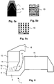
- FIG. 5a An example of such an advantageous staggering is in Fig. 5a shown schematically. It can, as in Fig. 5a it can be provided that the area size of the baffle elements 10 also increases with increasing distance of the baffle elements 10 from the injector unit 4. In this way, the proportion of the sprayed HWL, which impinges on the farther from the injector 4 more distant baffles 10, increases and thus improves the conditioning effect of this particular "rear" baffles 10. As in Fig. 5a 1, a width of the impact elements 10 which increases in or against the exhaust gas flow direction can also be provided at least in regions.
- FIG. 5b For example, a perforated embodiment is shown.
- Fig. 5c shows schematically a slotted shape. It is advantageous if the perforations of the baffle surface makes up about 5% to about 50% of the total gross area.
- a surface shaping of the baffles may be provided approximately in the form of nubs.
- a roughening and / or a coating may be provided. A preferred value for a surface roughness is in the range of 5 ⁇ m to 50 ⁇ m.
- a catalytic coating may be provided to aid in thermolysis and / or hydrolysis of urea. It is also possible to provide a coating which additionally or alternatively counteracts deposit formation with respect to deposition of urea decomposition products.
- the reducing agent treatment line 1 makes it possible, in particular by synergistic interaction of spraying and evaporation with subsequent flow direction deflection in conjunction with vortex formation, to provide extremely effective reducing agent treatment.
- HWL as a reducing agent
- an effective release of ammonia is achieved with a particularly good uniform distribution with short line lengths.
- the reducing agent treatment line 1 is characterized by a particularly low flow resistance.
- an additional installation element for mixing or swirl generation such as a static mixer before and especially after the HWL supply to the exhaust gas can be omitted.
- the illustrated as described and described reducing agent treatment line 1 therefore allows a particularly compact design of the exhaust system according to the invention, even with complex structure.
- a compact exhaust aftertreatment system in which two housings 13, 18 for exhaust aftertreatment components are connected to one another via the reducing agent treatment line 1.
- an oxidation catalyst is presently arranged in an upstream housing 13 in an upstream housing 13.
- a particle filter is arranged one behind the other and an SCR catalytic converter is arranged at a slight distance therefrom, wherein the particle filter is preferably provided with an SCR catalyst coating.
- An exhaust gas inlet funnel 15 of the upstream housing 13 receives exhaust gas of a diesel engine, not shown, and is for this purpose preferably connected to an exhaust gas turbocharger outlet, also not shown.
- Exhaust gas treated by the oxidation catalyst is supplied from the housing 13 via a housing outlet funnel 14 to the first exhaust pipe pipe section 2 of the reducing agent preparation section 1.
- the first exhaust pipe section 2 is by means of a in Fig. 6 injector unit, not shown, which is provided at a port 16, HWL injected into the exhaust.
- the supply of urea-containing or ammonia-containing exhaust gas to the housing 18 can be made particularly short.
- the described exhaust deflection by about 90 ° at the transition of the first exhaust pipe section 2 to the second exhaust pipe section 3 allows a particularly compact design of the exhaust aftertreatment system. Heat and pressure losses are minimized, which enables a particularly efficient exhaust gas purification.
- an embodiment of the exhaust system according to the invention has proven in which, as in Fig. 6 illustrated, the upstream housing 13 is oriented at least approximately vertically and the immediately downstream and connected via the reducing agent processing line 1 to the housing 13 downstream housing 18 is arranged at least approximately horizontally oriented.
- an arrangement is particularly compact and space-saving, in which the downstream housing 18 is at least partially disposed in the same geodetic height as the upstream housing 13. It is particularly preferred if the central axis of the housing 18 is arranged geodetically at least approximately as high or even higher than the downstream end of the housing 13.
Landscapes
- Chemical & Material Sciences (AREA)
- Engineering & Computer Science (AREA)
- Chemical Kinetics & Catalysis (AREA)
- Health & Medical Sciences (AREA)
- Toxicology (AREA)
- Combustion & Propulsion (AREA)
- Mechanical Engineering (AREA)
- General Engineering & Computer Science (AREA)
- Exhaust Gas After Treatment (AREA)
Description
Die Erfindung betrifft ein Abgassystem einer Brennkraftmaschine welches zur Abgasführung einen ersten zylindrischen Abgasleitungsrohrabschnitt und einen zweiten zylindrischen Abgasleitungsrohrabschnitt aufweist, wobei mit dem Reduktionsmittel angereichertes Abgas vom ersten Abgasleitungsrohrabschnitt in den zweiten Abgasleitungsrohrabschnitt überführbar ist. Ferner betrifft die Erfindung ein Verfahren zur Aufbereitung eines in ein Abgassystem einer Brennkraftmaschine eingebrachten Reduktionsmittels.The invention relates to an exhaust system of an internal combustion engine which has a first cylindrical exhaust pipe section and a second cylindrical exhaust pipe section for the exhaust system, wherein enriched with the reducing agent exhaust gas from the first exhaust pipe pipe section in the second exhaust pipe pipe section can be transferred. Furthermore, the invention relates to a method for processing a reductant introduced into an exhaust system of an internal combustion engine.
Zur Abgasnachbehandlung werden oftmals im Ausgangszustand flüssige Reduktionsmittel wie Mineralölkraftstoff oder wässrige Harnstofflösung ins Abgas von Brennkraftmaschinen eingebracht. Dabei besteht ein Problem in Bezug auf die Aufbereitung des in flüssigem Zustand eingebrachten Reduktionsmittels im Hinblick auf eine anzustrebende gleichmäßige Verteilung und im Hinblick auf eine Verdampfung. Bei wässriger Harnstofflösung besteht zusätzlich noch das Problem, durch Hydrolyse und/oder Thermolyse den zur selektiven katalytischen Stickoxid-Reduktion benötigten Ammoniak aus dem Harnstoff freizusetzen. Zur Lösung des Problems sind bereits eine Vielzahl von Abgassystemvarianten mit Aufbereitungsstrecken, Mischern, Verdampfern und Hydrolysekatalysatoren vorgeschlagen worden. Trotz der zahlreichen Lösungsvorschläge besteht weiterhin Verbesserungsbedarf in Bezug auf die Aufbereitung von insbesondere in flüssigem Zustand ins Abgas eingebrachten Reduktionsmitteln in dem vorstehend genannten Sinn.For exhaust aftertreatment liquid reducing agents such as mineral oil fuel or aqueous urea solution are often introduced into the exhaust gas of internal combustion engines in the initial state. There is a problem with respect to the treatment of the introduced in the liquid state reducing agent in view of a desirable uniform distribution and in terms of evaporation. In the case of aqueous urea solution, there is the additional problem of liberating the ammonia required for selective catalytic nitrogen oxide reduction from the urea by hydrolysis and / or thermolysis. To solve the problem, a variety of exhaust system variants have already been proposed with treatment lines, mixers, evaporators and hydrolysis catalysts. Despite the numerous proposed solutions, there is still room for improvement with regard to the treatment of reducing agents introduced into the exhaust gas, in particular in the liquid state, in the above-mentioned sense.
Die
Die
Die
Aufgabe der Erfindung ist es daher, eine Vorrichtung und ein Verfahren anzugeben, mit welchen eine möglichst gute Aufbereitung von in Abgas einer Brennkraftmaschine eingebrachtem Reduktionsmittel ermöglicht ist.The object of the invention is therefore to provide a device and a method with which the best possible treatment of introduced in the exhaust gas of an internal combustion engine reducing agent is made possible.
Diese Aufgabe wird durch ein Abgassystem mit den Merkmalen des Anspruchs 1 und durch ein Verfahren mit den Merkmalen des Anspruchs 10 gelöst.This object is achieved by an exhaust system having the features of
Das erfindungsgemäße Abgassystem weist zur Abgasführung einen ersten zylindrischen Abgasleitungsrohrabschnitt und einen zweiten zylindrischen Abgasleitungsrohrabschnitt auf. Dabei ist an dem ersten Abgasleitungsrohrabschnitt eine Injektoreinheit zur Einbringung eines Reduktionsmittels in durch den ersten Abgasleitungsrohrabschnitt strömendes Abgas angeordnet. Der zweite Abgasleitungsrohrabschnitt weist eine Zylinder-Mantelfläche, ein geschlossenes erstes Ende und ein offenes zweites Ende sowie eine Öffnung in der Zylinder-Mantelfläche angrenzend an das geschlossene Ende auf. Ein offenes Ende des ersten Abgasleitungsrohrabschnitts ist derart formschlüssig mit dem zweiten Abgasleitungsrohrabschnitt verbunden, dass aus dem offenen Ende des ersten Abgasleitungsrohrabschnitts ausströmendes Abgas in wenigstens annähernd senkrechter Richtung in Bezug auf eine Längserstreckung des zweiten Abgasleitungsrohrabschnitts durch die Öffnung in der Zylinder-Mantelfläche des zweiten Abgasleitungsrohrabschnitts in den zweiten Abgasleitungsrohrabschnitt einströmen kann. Somit erfolgt in unmittelbarem Anschluss an die Verbindungsstelle des ersten Abgasleitungsrohrabschnitts mit dem zweiten Abgasieitungsrohrabschnitt eine Umlenkung der Hauptströmungsrichtung des mit dem Reduktionsmittel angereicherten Abgases um wenigstens annähernd 90 Grad, wodurch eine Verwirbelung des Abgases und eine gute Vermischung des Reduktionsmittels im Abgas erzielt wird. Die Öffnung in der Zylinder-Mantelfläche des zweiten Abgasleitungsrohrabschnitts weist in Richtung der Längserstreckung des zweiten Abgasleitungsrohrabschnitts eine größere Ausdehnung auf als quer zur Längserstreckung. Die Öffnung weist bevorzugt eine ovale bzw. ellipsenförmige Form auf. Es kann jedoch auch ein etwa rechteckförmiger Ausschnitt in der Zylinder-Mantelfläche vorgesehen sein. Die Längsausdehnung ist dabei etwa 1,5 bis 4 mal größer als die Querausdehnung. Infolge dieser Ausführungsform ist die Ausbildung eines besonders stabilen rotierenden Abgaswirbels im zweiten Abgasleitungsrohrabschnitt ermöglicht. Dies wiederum ermöglicht eine kurze Ausführung des zweiten Abgasleitungsrohrabschnitts bzw. einen kurze Leitungslänge bis zur anschließenden Abgasreinigungseinheit und damit eine kompakte Bauform des Abgassystems mit einer kurzen Reduktionsmittelaufbereitungsstrecke. Infolge der Verwirbelung und der dadurch bedingten Vermischung kann in vorteilhafter Weise auf einen separaten Mischer zur Verteilung von ins Abgas eingebrachtem Reduktionsmittel in der Reduktionsmittelaufbereitungsstrecke verzichtet und ein dadurch verursachter Druckverlust vermieden werden. Die Injektoreinheit ist bevorzugt so ausgebildet, dass sie das vorzugsweise flüssig vorliegende Reduktionsmittel fein vernebelt ins Abgas eindüsen bzw. einspritzen kann.The exhaust system according to the invention comprises a first cylindrical exhaust pipe pipe section and a second cylindrical exhaust pipe pipe section for the exhaust gas guide. In this case, an injector unit for introducing a reducing agent into exhaust gas flowing through the first exhaust pipe pipe section is arranged on the first exhaust pipe pipe section. The second exhaust pipe pipe section has a cylinder jacket surface, a closed first end and an open second end and an opening in the cylinder jacket surface adjacent to the closed end. An open end of the first exhaust pipe pipe section is connected in such a form-fitting manner to the second exhaust pipe pipe section that exhaust gas flowing out of the open end of the first exhaust pipe pipe section is in at least approximately vertical direction with respect to a longitudinal extension of the second exhaust pipe pipe section through the opening in the cylindrical surface of the second exhaust pipe section can flow into the second exhaust pipe section. Thus, in direct connection to the junction of the first exhaust pipe pipe section with the second Abgasieitungsrohrabschnitt a deflection of the main flow direction of the enriched with the reducing agent exhaust gas by at least approximately 90 degrees, whereby a turbulence of the exhaust gas and a good mixing of the reducing agent is achieved in the exhaust gas. The opening in the cylinder jacket surface of the second exhaust pipe pipe section has a greater extent in the direction of the longitudinal extent of the second exhaust pipe pipe section than transverse to the longitudinal extent. The opening preferably has an oval or elliptical shape. However, it can also be provided an approximately rectangular cutout in the cylinder jacket surface. The longitudinal extent is about 1.5 to 4 times greater than the transverse extent. As a result of this embodiment, the formation of a particularly stable rotating exhaust vortex in the second exhaust pipe section is possible. This in turn allows a short design of the second exhaust pipe section or a short line length to the subsequent exhaust gas cleaning unit and thus a compact design of the exhaust system with a short reducing agent treatment line. As a result of the turbulence and the consequent mixing can be dispensed advantageously on a separate mixer for the distribution of reducing agent introduced into the exhaust gas in the reducing agent processing line and thereby caused pressure loss can be avoided. The injector unit is preferably designed such that it can inject or inject the finely atomized, preferably liquid, reducing agent into the exhaust gas.
Die Randkontur des offenen Endes des ersten Abgasleitungsrohrabschnitts entspricht vorzugsweise der Randkontur der Öffnung in der Zylinder-Mantelfläche des zweiten Abgasleitungsrohrabschnitts und die formschlüssige Verbindung der beiden Abgasleitungsrohrabschnitte, etwa durch Verschweißen bewerkstelligt, ist entlang dieser Kontur gegeben. Vorzugsweise endet der erste Abgasieitungsrohrabschnitt auf der Zylinder-Mantelfläche des zweiten Abgasleitungsrohrabschnitts und ragt somit nicht in den Innenraum des zweiten Abgasleitungsrohrabschnitts hinein. Die Öffnung in der Zylinder-Mantelfläche des zweiten Abgasleitungsrohrabschnitts ist unmittelbar angrenzend oder mit geringem Abstand von vorzugsweise wenigen Millimetern an dem endseitigen Verschluss des zweiten Abgasleitungsrohrabschnitts angeordnet. Dadurch werden strömungsmäßige Totzonen vermieden. Zum Verschluss des zweiten Abgasleitungsrohrabschnitts an seinem ersten Ende kann ein den Leitungsquerschnitt abdeckender, insbesondere eben ausgeführter Deckel vorgesehen sein, dessen Normalenrichtung mit der Zylinderachsrichtung des zweiten Abgasleitungsrohrabschnitts gleichgerichtet ist. Die Querschnittsflächen des ersten Abgasleitungsrohrabschnitts und des zweiten Abgasleitungsrohrabschnitts sind zumindest im Bereich ihrer Verbindungsstelle wenigstens annähernd gleich, unterscheiden sich jedoch bevorzugt weniger als um den Faktor 1,5 voneinander. Aus dem offenen Ende des zweiten Abgasleitungsrohrabschnitts ausströmendes Abgas wird vorzugsweise einer katalytischen Abgasreinigungseinheit wie einem SCR-Katalysator, einem Hydrolysekatalysator, einem Oxidationskatalysator, einem Stickoxid-Speicherkatalysator oder einem Partikelfilter zugeleitet.The edge contour of the open end of the first exhaust pipe pipe section preferably corresponds to the edge contour of the opening in the cylinder jacket surface of the second exhaust pipe pipe section and the positive connection of the two exhaust pipe pipe sections, as effected by welding is given along this contour. The first exhaust pipe section preferably ends on the cylinder jacket surface of the second exhaust pipe pipe section and thus does not project into the interior of the second exhaust pipe pipe section. The opening in the cylinder jacket surface of the second exhaust pipe section is disposed immediately adjacent or at a small distance of preferably a few millimeters at the end-side closure of the second exhaust pipe section. This will be fluid dead zones avoided. For closing the second exhaust pipe pipe section at its first end may be provided a line cross-section covering, in particular flat executed lid whose normal direction is rectified with the cylinder axis direction of the second exhaust pipe pipe section. The cross-sectional areas of the first exhaust pipe pipe section and the second exhaust pipe pipe section are at least approximately the same at least in the region of their connection point, but preferably differ less than by a factor of 1.5 from one another. Exhaust gas flowing out of the open end of the second exhaust pipe section is preferably fed to a catalytic exhaust gas purification unit such as an SCR catalyst, a hydrolysis catalyst, an oxidation catalyst, a nitrogen oxide storage catalyst or a particulate filter.
In Ausgestaltung der Erfindung ist die Injektoreinheit in geringer Entfernung stromauf von der Verbindungsstelle des ersten Abgasleitungsrohrabschnitts mit dem zweiten Abgasleitungsrohrabschnitt angeordnet. Vorzugsweise beträgt die Entfernung weniger als ein Durchmesser eines der Abgasleitungsrohrabschnitte, insbesondere weniger als die Hälfte oder ein Drittel davon. Das Bauvolumen der Reduktionsmittelaufbereitungsstrecke bzw. die zur Reduktionsmittelaufbereitung eingesetzten reduktionsmittelführenden Leitungslängen können daher besonders gering gehalten werden.In an embodiment of the invention, the injector unit is arranged at a short distance upstream of the connection point of the first exhaust pipe pipe section with the second exhaust pipe pipe section. Preferably, the distance is less than a diameter of one of the exhaust pipe pipe sections, in particular less than half or one third thereof. The volume of construction of the reducing agent preparation section or the reducing agent-carrying line lengths used for reducing agent preparation can therefore be kept particularly low.
In weiterer Ausgestaltung der Erfindung ist in geringer Entfernung stromauf von der Verbindungsstelle des ersten Abgasleitungsrohrabschnitts mit dem zweiten Abgasleitungsrohrabschnitt innerhalb des ersten Abgasleitungsrohrabschnitts wenigstens ein plattenförmiges Prallelement angeordnet, auf welchem mittels der Injektoreinheit in den ersten Abgasleitungsrohrabschnitt eingebrachtes Reduktionsmittel aufprallt. Das plattenförmige Prallelement wirkt dabei als Verdampferelement. Die zur Verdampfung des flüssigen, bevorzugt in Form kleiner Tröpfchen vorliegenden Reduktionsmittels erforderliche Wärmeenergie wird vorzugsweise durch Wärmetausch mit dem angeströmten Abgas aufgenommen. Es kann jedoch auch eine separate Beheizung des Prallelements vorgesehen sein. Durch Aufprall der Reduktionsmitteltröpfchen auf das aufgeheizte Prallelement erfolgt eine wenigstens teilweise Verdampfung des Reduktionsmittels und zusätzlich eine weitere Verkleinerung der Tröpfchengröße von abprallenden Reduktionsmitteltröpfchen. Dadurch ist eine Verteilung des Reduktionsmittels im Abgas im Vergleich zu einem überwiegend in Tröpfchenform vorliegenden Reduktionsmittel verbessert. Weiterhin ist der Verdampfungsvorgang infolge des gegenüber einer alleinigen Wärmeübertragung aus dem Abgas verbesserten Wärmeübergangs von der Verdampferplatte auf aufgepralltes Reduktionsmittel verbessert. Als Folge der wenigstens teilweisen Verdampfung des Reduktionsmittels bereits an dem Prallelement ist eine weitere Verkürzung der Reduktionsmittelaufbereitungsstrecke ermöglicht. Vorzugsweise ist das Prallelement direkt über bzw. vor der Öffnung in der Zylinder-Mantelfläche des zweiten Abgasleitungsrohrabschnitts angeordnet. Das dem zweiten Abgasleitungsrohrabschnitt zugewandte Ende des Prallelements kann etwa in der Öffnungsfläche oder einige Millimeter, jedoch vorzugsweise allenfalls wenige Zentimeter in Richtung des ersten Abgasleitungsrohrabschnitts versetzt hierzu angeordnet sein. Das Prallelement kann als ebenes oder mit oberflächenvergrößernden Prägungen versehenes Blech ausgebildet sein. Das Blech kann ferner geschlitzt oder gelocht ausgeführt sein und mit einer eine Harnstoffhydrolyse fördernden oder eine Belagsbildung vermindernden Beschichtung, beispielsweise aus Titandioxid versehen, oder aufgeraut sein.In a further embodiment of the invention, at least one plate-shaped baffle element is arranged at a short distance upstream of the connection point of the first exhaust pipe pipe section to the second exhaust pipe section within the first exhaust pipe pipe section, on which the reducing agent introduced into the first exhaust pipe pipe section by means of the injector unit impinges. The plate-shaped baffle acts as an evaporator element. The heat energy required for the evaporation of the liquid reducing agent, preferably in the form of small droplets, is preferably absorbed by heat exchange with the exhaust gas flown through. However, it can also be provided a separate heating of the impact element. Impact of the reducing agent droplets on the heated impact element results in at least partial evaporation of the reducing agent and, in addition, a further reduction in the droplet size of rebounding reductant droplets. As a result, a distribution of the reducing agent in the exhaust gas is improved compared to a reducing agent predominantly present in droplet form. Furthermore, the evaporation process is due to the opposite of a sole heat transfer improved from the exhaust gas improved heat transfer from the evaporator plate to impacted reducing agent. As a result of the at least partial evaporation of the reducing agent already at the impact element, a further shortening of the reducing agent preparation section is made possible. The baffle element is preferably arranged directly above or in front of the opening in the cylinder jacket surface of the second exhaust pipe pipe section. The end of the impact element facing the second exhaust pipe pipe section may be arranged offset in the direction of the first exhaust pipe pipe section approximately in the opening area or a few millimeters, but preferably at most a few centimeters. The baffle element may be formed as a flat or provided with surface enlarging embossing sheet. The sheet may further be slit or perforated, and provided with a urea hydrolysis-promoting or deposit-reducing coating, such as titanium dioxide, or roughened.
In einer bevorzugten weiteren Ausführungsform ist das Prallelement wenigstens annähernd eben ausgebildet, wobei ein Normalenvektor der Prallelementebene wenigstens annähernd senkrecht zur Abgasströmungsrichtung orientiert ist. Somit liegt ein Richtungsvektor der Abgasströmungsrichtung etwa in der Ebene des Prallelements. Dadurch ist ein niedriger Strömungswiderstand ermöglicht. Vorzugsweise ist die Richtung des Normalenvektors wenigstens annähernd parallel zur Zylinderachsrichtung des zweiten Abgasleitungsrohrabschnitts im Bereich der Öffnung in dessen Zylinder-Mantelfläche orientiert.In a preferred further embodiment, the baffle element is at least approximately planar, wherein a normal vector of the baffle plane is oriented at least approximately perpendicular to the exhaust gas flow direction. Thus, a directional vector of the exhaust gas flow direction is located approximately in the plane of the impact element. This allows a low flow resistance. Preferably, the direction of the normal vector is oriented at least approximately parallel to the cylinder axis direction of the second exhaust pipe pipe section in the region of the opening in its cylinder jacket surface.
Die Verdampfungsrate von mittels der Injektoreinheit ins Abgas eingebrachtem Reduktionsmittel lässt sich weiter vergrößern, wenn in weiterer Ausgestaltung der Erfindung eine Mehrzahl von Prallelementen vorgesehen wird. Die Prallelemente sind bevorzugt parallel zueinander orientiert, insbesondere fluchtend hintereinander und über der Öffnung in der Zylinder-Mantelfläche des zweiten Abgasleitungsrohrabschnitts angeordnet. Je nach Größe der Öffnung in der Zylinder-Mantelfläche des zweiten Abgasleitungsrohrabschnitts können zwei bis acht Prallelemente vorgesehen sein. Vorzugsweise sind vier Prallelemente vorgesehen. In Bezug auf den von der Injektoreinheit abgegebenen Sprühkegel des Reduktionsmittels sind die Prallelemente so angeordnet, dass jedes von ihnen wenigstens teilweise vom Sprühkegel erfasst wird und damit zur Verdampfung des Reduktionsmittels beitragen kann. Hierzu ist es wiederum bevorzugt, wenn die flächenmäßige Ausdehnung der Prallelemente unterschiedlich gewählt ist. Besonders bevorzugt ist es in diesem Zusammenhang, wenn die Fläche der Prallelemente mit wachsendem Abstand zur Injektoreinheit zunimmt. In Richtung der Flächennormalen gesehen deckt in dieser Ausführungsform ein Prallelement lediglich einen Teil des Flächenbereichs des benachbarten, folgenden Prallelements ab.The evaporation rate of reducing agent introduced into the exhaust gas by means of the injector unit can be further increased if, in a further embodiment of the invention, a plurality of impact elements is provided. The baffle elements are preferably oriented parallel to one another, in particular arranged in alignment one behind the other and above the opening in the cylinder jacket surface of the second exhaust pipe pipe section. Depending on the size of the opening in the cylinder jacket surface of the second exhaust pipe section, two to eight baffles may be provided. Preferably, four baffles are provided. With respect to the spray cone of the reducing agent emitted by the injector unit, the baffle elements are arranged such that each of them is at least partially caught by the spray cone and can thus contribute to the evaporation of the reducing agent. For this purpose, it is again preferred if the areal extent of the impact elements differs is selected. It is particularly preferred in this context if the surface of the impact elements increases with increasing distance from the injector unit. Seen in the direction of the surface normal, in this embodiment, a baffle element only covers part of the surface area of the adjacent, following baffle element.
Erfindungsgemäß ist eine Zylinderachse des ersten Abgasleitungsrohrabschnitts im Bereich der Verbindungsstelle mit dem zweiten Abgasleitungsrohrabschnitt auf einen Zentrumsbereich einer Querschnittsfläche des zweiten Abgasleitungsrohrabschnitts gerichtet. Die Zufuhr des mit dem Reduktionsmittel angereicherten Abgases in den zweiten Abgasleitungsrohrabschnitt erfolgt demnach sozusagen mittig in den zweiten Abgasleitungsrohrabschnitt. Infolge dessen bilden sich innerhalb des zweiten Abgasleitungsrohrabschnitts zwei gegenläufig rotierende Abgasströmungswirbel aus. Dies ermöglicht eine besonders gute Vermischung des Reduktionsmittels im Abgas. Zudem ist der tatsächliche Abgasströmungsweg gegenüber der geometrischen Länge des zweiten Abgasleitungsrohrabschnitts vergrößert. Somit ist eine Verdampfung von im Abgas verbliebenen Reduktionsmitteltröpfchen verbessert. Im Falle von Harnstoff als Reduktionsmittel ist auch dessen Hydrolyse bzw. Thermolyse verbessert.According to the invention, a cylinder axis of the first exhaust pipe pipe section is directed in the region of the connection point with the second exhaust pipe pipe section to a center region of a cross-sectional surface of the second exhaust pipe pipe section. The supply of the enriched with the reducing agent exhaust gas in the second exhaust pipe section is thus carried out, so to speak, centrally in the second exhaust pipe pipe section. As a result, two counter-rotating exhaust gas flow vortices are formed within the second exhaust pipe pipe section. This allows a particularly good mixing of the reducing agent in the exhaust gas. In addition, the actual exhaust gas flow path relative to the geometric length of the second exhaust pipe pipe section is increased. Thus, evaporation of reducing agent droplets remaining in the exhaust gas is improved. In the case of urea as a reducing agent and its hydrolysis or thermolysis is improved.
Die Verteilung des Reduktionsmittels im Abgas lässt sich weiter verbessern, wenn in weiterer Ausgestaltung der Erfindung der zweite Abgasleitungsrohrabschnitt im Bereich der Öffnung in der Zylinder-Mantelfläche eine ovale Querschnittsform aufweist. In diesem Fall bilden sich zwei gegenläufige Abgasströmungswirbel mit in einer Draufsicht annähernd jeweils Kreisform aus. Die Abgasströmungswirbel sind infolgedessen besonders stabil.The distribution of the reducing agent in the exhaust gas can be further improved if, in a further embodiment of the invention, the second exhaust pipe pipe section has an oval cross-sectional shape in the region of the opening in the cylinder jacket surface. In this case, two opposing exhaust gas flow vortices form approximately circular in plan view. As a result, the exhaust gas flow vortices are particularly stable.
Es ist auch denkbar, dass eine Zylinderachse des ersten Abgasleitungsrohrabschnitts im Bereich der Verbindungsstelle mit dem zweiten Abgasleitungsrohrabschnitt auf einen außermittigen Bereich einer Querschnittsfläche des zweiten Abgasleitungsrohrabschnitts gerichtet ist. Das Abgas wird damit außermittig, insbesondere annähernd tangential in Bezug auf den zweiten Abgasleitungsrohrabschnitt in diesen eingeleitet. In Verbindung mit einer hierfür vorzugsweise vorgesehenen kreisrunden Querschnittsform des zweiten Abgasleitungsrohrabschnitts im Bereich der Öffnung ist die Ausbildung eines nahezu den gesamten Querschnitt erfassenden Abgasströmungswirbels ermöglicht.It is also conceivable that a cylinder axis of the first exhaust pipe pipe section in the region of the connection point with the second exhaust pipe pipe section is directed to an off-center region of a cross-sectional area of the second exhaust pipe pipe section. The exhaust gas is thus introduced eccentrically, in particular approximately tangentially with respect to the second exhaust pipe pipe section in this. In conjunction with a preferably provided for this purpose circular cross-sectional shape of the second exhaust pipe section in the region of the opening of the formation of a nearly the entire cross-section detecting exhaust gas flow vortex is possible.
Das erfindungsgemäße Verfahren zur Aufbereitung eines in einen ersten Abgasleitungsrohrabschnitt eines Abgassystems einer Brennkraftmaschine eingebrachten Reduktionsmittels sieht vor, dass das eingebrachte Reduktionsmittel an einer in dem ersten Abgasleitungsrohrabschnitt angeordneten Verdampfereinrichtung wenigstens teilweise verdampft und anschließend zusammen mit dem Abgas der Brennkraftmaschine in einer Richtung durch eine Öffnung in einer Zylinder-Mantelfläche eines zweiten Abgasleitungsrohrabschnitts in den zweiten Abgasieitungsrohrabschnitt einströmt, die wenigstens annähernd senkrecht zu einer axialen Richtung des zweiten Abgasleitungsrohrabschnitts orientiert ist, wobei innerhalb des zweiten Abgasleitungsrohrabschnitts eine rotierende Abgasströmung ausgebildet wird. Infolge der wenigstens teilweisen Verdampfung, welche durch die Verdampfereinrichtung ermöglicht ist, kann in Verbindung mit der anschließenden Verwirbelung nach Zufuhr des Abgases in den zweiten Abgasleitungsrohrabschnitt eine besonders gute Aufbereitung des Reduktionsmittels erzielt werden. Die Leitungslänge der Reduktionsmittelaufbereitungsstrecke kann dabei kurz gehalten werden und es ist eine kompakte Bauform ermöglicht.The inventive method for processing a introduced into a first exhaust pipe section of an exhaust system of an internal combustion engine reducing agent provides that the introduced reducing agent at a arranged in the first exhaust pipe pipe section evaporator at least partially evaporated and then together with the exhaust gas of the internal combustion engine in one direction through an opening in one Cylinder lateral surface of a second exhaust pipe pipe section flows into the second Abgasieitungsrohrabschnitt which is oriented at least approximately perpendicular to an axial direction of the second exhaust pipe pipe section, wherein within the second exhaust pipe pipe section, a rotating exhaust gas flow is formed. As a result of the at least partial evaporation, which is made possible by the evaporator device, a particularly good treatment of the reducing agent can be achieved in connection with the subsequent turbulence after supply of the exhaust gas into the second exhaust pipe section. The line length of the reducing agent preparation section can be kept short and it is a compact design allows.
In Ausgestaltung des Verfahrens sind als Verdampfereinrichtung eine Mehrzahl von Verdampferplatten vorgesehen und das Reduktionsmittel wird derart in den ersten Abgasleitungsrohrabschnitt eingedüst, dass es auf alle Verdampferplatten aufprallt. Dadurch ist die Verdampfung des Reduktionsmittels verbessert, wobei eine besonders hohe Verdampfungsrate erzielt wird, wenn das Reduktionsmittel in einem höchstens spitzen Winkel in Bezug auf eine Normalenrichtung der Verdampferplatten in den ersten Abgasleitungsrohrabschnitt eingespritzt wird. Das Reduktionsmittel wird somit derart eingedüst, dass es wenigstens annähernd senkrecht auf die Verdampferplatten auftritt, womit eine gute Benetzung der Verdampferplattenoberflächen erreicht wird. Der Auftreffwinkel von eingesprühtem Reduktionsmittel auf eine Verdampferplatte beträgt bevorzugt weniger als 45 Grad in Bezug auf die Normalenrichtung der Verdampferplatte.In an embodiment of the method, a plurality of evaporator plates are provided as the evaporator device and the reducing agent is injected into the first exhaust pipe section in such a way that it impinges on all evaporator plates. Thereby, the evaporation of the reducing agent is improved, whereby a particularly high evaporation rate is achieved when the reducing agent is injected at a maximum acute angle with respect to a normal direction of the evaporator plates in the first exhaust pipe pipe section. The reducing agent is thus injected so that it occurs at least approximately perpendicular to the evaporator plates, whereby a good wetting of the evaporator plate surfaces is achieved. The angle of incidence of sprayed reducing agent on an evaporator plate is preferably less than 45 degrees with respect to the normal direction of the evaporator plate.
Weiterhin ist es bevorzugt, wenn in weiterer Ausgestaltung des Verfahrens das Reduktionsmittel wenigstens annähernd senkrecht in Bezug auf eine Abgasströmung in den ersten Abgasleitungsrohrabschnitt eingespritzt wird.Furthermore, it is preferred if, in a further embodiment of the method, the reducing agent is injected at least approximately perpendicularly with respect to an exhaust gas flow into the first exhaust pipe pipe section.
In weiterer Ausgestaltung des Verfahrens bildet das in den zweiten Abgasleitungsrohrabschnitt einströmende Abgas zwei in Bezug auf eine axiale Richtung des zweiten Abgasleitungsrohrabschnitts gesehen gegensinnig rotierende Wirbel aus. Dadurch ist eine besonders wirksame und gleichmäßige Vermischung des Reduktionsmittels im Abgas ermöglicht. Angestrebt ist eine stabile Wirbelausbildung, welche bevorzugt wenigstens teilweise bis zum Erreichen der Eintrittseite einer der Wirbelmischstrecke nachgeschalteten Abgasreinigungskomponente bzw. deren gegebenenfalls vorgesehenen Gehäuseeinlauftrichter erhalten bleibt. Dies kann insbesondere dadurch erreicht werden, wenn durch eine ovale Querschnittsform des zweiten Abgasleitungsrohrabschnitts für eine Ausbildung von zwei gegensinnig rotierenden Wirbeln mit wenigstens annähernder Kreisform gesorgt wird.In a further refinement of the method, the exhaust gas flowing into the second exhaust-gas pipe section forms two vortices which rotate in opposite directions, viewed in relation to an axial direction of the second exhaust-gas pipe section. This is one allows particularly effective and uniform mixing of the reducing agent in the exhaust gas. The aim is a stable vortex formation, which preferably at least partially until reaching the inlet side of the vortex mixing section downstream exhaust gas purification component or its optionally provided housing inlet funnel is maintained. This can be achieved in particular by providing an oval cross-sectional shape of the second exhaust pipe section for forming two counter-rotating vortices with at least approximately circular shape.
Weitere Vorteile, Merkmale und Einzelheiten der Erfindung ergeben sich aus der nachfolgenden Beschreibung bevorzugter Ausführungsbeispiele sowie anhand der Zeichnungen. Die vorstehend in der Beschreibung genannten Merkmale und Merkmalskombinationen sowie die nachfolgend in den Figurenbeschreibungen genannten und/oder in den Figuren alleine gezeigten Merkmale und Merkmalskombinationen sind nicht nur in der jeweils angegeben Kombination sondern auch in anderen Kombinationen oder in der Alleinstellung verwendbar, ohne den Rahmen der Erfindung zu verlassen. Die Figuren zeigen in:
- Fig. 1
- eine schematische Darstellung eines eine Reduktionsmittelaufbereitungsstrecke bildenden Teilabschnitts des erfindungsgemäßen Abgassystems,
- Fig. 2
- eine schematische Darstellung eines Abgasströmungsmusters in der Reduktionsmittelaufbereitungsstrecke nach
Fig. 1 , - Fig. 3
- eine schematische Darstellung einer weiteren vorteilhaften Ausführungsform eines eine Reduktionsmittelaufbereitungsstrecke bildenden Teilabschnitts des erfindungsgemäßen Abgassystems analog
Fig. 1 , - Fig. 4
- eine schematische Darstellung einer alternativen Ausführungsform eines eine Reduktionsmittelaufbereitungsstrecke bildenden Teilabschnitts eines Abgassystems,
- Fig. 5
- vorteilhafte Ausführungsformen für Prallelemente des erfindungsgemäßen Abgassystems, und
- Fig. 6
- eine Darstellung eines Teilbereichs des erfindungsgemäßen Abgassystems mit durch eine Reduktionsmittelaufbereitungsstrecke verbundenen Abgasnachbehandlungsbauteilen.
- Fig. 1
- a schematic representation of a reducing agent processing section forming a portion of the exhaust system according to the invention,
- Fig. 2
- a schematic representation of an exhaust gas flow pattern in the reducing agent preparation section according to
Fig. 1 . - Fig. 3
- a schematic representation of a further advantageous embodiment of a reducing agent preparation section forming part of the inventive exhaust system analog
Fig. 1 . - Fig. 4
- FIG. 2 is a schematic representation of an alternative embodiment of a section of an exhaust system forming a reducing agent preparation section. FIG.
- Fig. 5
- advantageous embodiments for impact elements of the exhaust system according to the invention, and
- Fig. 6
- a representation of a portion of the exhaust system according to the invention with connected by a reducing agent treatment line exhaust aftertreatment components.
Der in
Vorliegend weisen sowohl der Querschnitt des ersten Abgasleitungsrohrabschnitts 2 als auch der Querschnitt des zweiten Abgasleitungsrohrabschnitts 3 an der Einmündungsstelle eine ovale bzw. elliptische Form auf. Dementsprechend weist auch die Öffnung 8 eine ovale oder elliptische Form auf, wobei die längere Achse der elliptisch geformten Öffnung 8 parallel zur Zylinderachse 12 des zweiten Abgasleitungsrohrabschnitts 3 orientiert ist. Die in Richtung der Zylinderachse 12 des zweiten Abgasleitungsrohrabschnitts 3 verlaufende längere Ausdehnung a der elliptischen Öffnung 8 und damit auch des ersten Abgasleitungsrohrabschnitts 2 an der Verbindung von erstem Abgasleitungsrohrabschnitt 2 und zweitem Abgasleitungsrohrabschnitt 3 ist somit größer als die hierzu senkrecht orientierte Querausdehnung b. Das Verhältnis a/b liegt dabei bevorzugt im Bereich zwischen 1,5 und 4.In the present case, both the cross section of the first exhaust
Entsprechend der wenigstens annähernd senkrechten Einmündung des ersten Abgasleitungsrohrabschnitts 2 in den zweiten Abgasleitungsrohrabschnitt 3 ist die kürzere Achse b der elliptischen Öffnung 8 bzw. des ersten Abgasleitungsrohrabschnitts 2 an der Einmündestelle wenigstens annähernd parallel zur größeren Querschnittsachse d des zweiten elliptischen Abgasleitungsrohrabschnitts 3 orientiert. Die kürzere Achse c der elliptischen Querschnittsfläche des zweiten Abgasleitungsrohrabschnitts 3 ist demnach an der Einmündestelle parallel zur Zylinderachse 11 des ersten Abgasleitungsrohrabschnitts 2 orientiert. Vorzugsweise liegt das Verhältnis d/c von längerer Querschnittsachse d und kürzerer Querschnittsachse c des zweiten Abgasleitungsrohrabschnitts 3 im Bereich zwischen 1,5 bis 2. Dabei ist die kürzere Querabmessung b der Öffnung 8 vorzugsweise kleiner als die kürzere Querschnittsachse c des zweiten Abgasleitungsrohrabschnitts 3. Für Hubraumgrößen im Bereich von etwa 1,6 Liter bis 3,5 Liter der Brennkraftmaschine wird die kürzere Querschnittsachse c vorzugsweise im Bereich von 30 mm bis 100 mm gewählt.Corresponding to the at least approximately vertical junction of the first
Abgas einer nicht dargestellten Brennkraftmaschine, insbesondere eines Dieselmotors, strömt aus einer in
Eingesprühtes Reduktionsmittel trifft, wie durch gepunktet dargestellte Pfeile dargestellt, auf als Verdampferplatten wirkende Prallelemente 10, die über der Öffnung 8 in der Zylinder-Mantelfläche des zweiten Abgasleitungsrohrabschnitts 3 angeordnet sind. Verdampftes oder von den Verdampferplatten abprallendes flüssiges Reduktionsmittel wird von der Abgasströmung erfasst und mitgerissen. Auf Besonderheiten der Reduktionsmitteleindüsung und -Verdampfung sowie auf Ausgestaltung, Anordnung und Funktion der Prallelemente wird weiter unten genauer eingegangen.Sprayed reducing agent meets, as shown by dotted arrows, acting as evaporator plates baffles 10, which are arranged above the
Mit HWL versetztes Abgas strömt sodann in im Wesentlichen senkrechter Richtung in Bezug auf die Zylinderachse 12 des zweiten Abgasleitungsrohrabschnitts 3 durch die Öffnung 8 in diesen ein. In den zweiten Abgasleitungsrohrabschnitt 3 einströmendes Abgas wird durch diesen hindurchgeleitet und strömt aus einem offenen Ende 7 aus. An dem offenen Ende ist eine nicht dargestellte Abgasreinigungskomponente, vorzugsweise über einen Einlauftrichter, mit dem zweiten Abgasleitungsrohrabschnitt 3 verbunden. Bei der Abgasreinigungskomponente handelt es sich bevorzugt um ein katalytisch und/oder filtertechnisch wirksames Bauteil. Vorzugsweise ist an dem offenen Ende 7 des zweiten Abgasleitungsrohrabschnitts 3 ein Gehäuse angeschlossen, in welchem ein Partikelfilter untergebracht ist.Exhaust gas added with HWL then flows in a substantially vertical direction with respect to the
Gegenüberliegend zum offenen Ende 7 weist der zweite Abgasleitungsrohrabschnitt 3 ein geschlossenes Ende 6 auf. Hierfür kann beispielsweise ein ebener Verschlussdeckel angeschweißt sein. Aus dem ersten Abgasleitungsrohrabschnitt 2 durch die Öffnung 8 in der Zylinder-Mantelfläche des zweiten Abgasleitungsrohrabschnitts 3 in diesen einströmendes Abgas wird in daher in seiner Hauptströmungsrichtung um etwa 90 ° umgelenkt. Es ist vorzugsweise vorgesehen, dass das in Bezug auf die umgelenkte Hauptströmungsrichtung des Abgases stromaufwärtige Ende der Öffnung 8 unmittelbar an das geschlossene Ende 6 angrenzt oder zumindest nahe zu diesem angeordnet ist. Dadurch wird die Ausbildung einer strömungsmäßigen Totzone am geschlossenen Ende 6 des zweiten Abgasleitungsrohrabschnitts 3 vermieden.Opposite the
In den zweiten Abgasleitungsrohrabschnitt 3 einströmendes Abgas trifft auf einen der Öffnung 8 gegenüberliegenden Bereich der Innenwand des zweiten Abgasleitungsrohrabschnitts 3 auf und wird umgelenkt. Dabei entstehen insbesondere infolge der elliptischen Rohrquerschnittsform zwei gegensinnig rotierende Wirbel, wie durch die gestrichelten Pfeile 5' dargestellt. Die Ausbildung von zwei gegensinnig rotierenden Abgaswirbeln hat sich als ganz besonders vorteilhaft in Bezug auf die Aufbereitung des Reduktionsmittels erwiesen. Einerseits wird eine Gleichverteilung von flüssigem, dabei gegebenenfalls überwiegend in Form von kleinen Tröpfchen vorliegendem Reduktionsmittel, und besonders von bereits verdampftem Reduktionsmittel verbessert. Andererseits wird durch die Verwirbelung die Verdampfung von HWL entscheidend verbessert. Und schließlich wird eine Freisetzung von Ammoniak durch Thermolyse und/oder Hydrolyse verbessert. Weiterhin erfolgt durch das Auftreffen des Abgases auf die der Öffnung 8 gegenüberliegende Rohrinnenwand ein weiteres Aufbrechen von im Abgas vorhandenen Tröpfchen, wodurch deren nachfolgende Verdampfung erleichtert ist. Soweit eine Benetzung der Rohrinnenwand auftritt, wirkt die benetzte Rohrfläche außerdem als Verdampferfläche, wodurch die Verdampfung der HWL weiter verbessert ist.In the second exhaust
Zur Verdeutlichung der Doppelwirbelausbildung ist in
Zur Ausbildung von an eine Kreisform möglichst gut angenäherten Abgaswirbeln kann auch eine Querschnittsform des zweiten Abgasleitungsrohrabschnitts 3 gewählt werden, welche zwei aneinandergesetzten Kreissegmenten entspricht, wie dies grob schematisch in
Die Vorteile der oben erläuterten Ausführungsformen der Reduktionsmittelaufbereitungsstrecke 1 lassen sich gegebenenfalls auch mit abgewandelten Querschnittsformen der Abgasleitungsrohrabschnitte 2, 3 und mit veränderten Querschnittsgeometrien sowie veränderten Strömungsverhältnissen erzielen. Dabei ist es jedoch erforderlich, die Drall erzeugenden Eigenschaften im Wesentlichen beizubehalten. Eine in diesem Sinne ebenfalls denkbare alternative Ausführungsform eines eine Reduktionsmittelaufbereitungsstrecke bildenden Teilabschnitts ist in
Die in
Der zweite Abgasleitungsrohrabschnitt 3 weist in dieser Ausführungsform einen kreisrunden Querschnitt auf, weshalb anstelle eines Doppelwirbels wie dargestellt ein Einfachwirbel ausgebildet wird. Der Durchmesser D des zweiten Abgasleitungsrohrabschnitts 3 liegt bevorzugt im Bereich der Querschnittsabmessungen c und d der in
Weiterhin ist die Querschnittsform des ersten Abgasleitungsrohrabschnitts vorliegend rechteckig gewählt. Dabei gelten weiterhin die zur Ausführungsform von
Nachfolgend wird auf die erfindungsgemäß vorgesehene Verdampfereinrichtung eingegangen, welche stromaufwärts von der Verbindungsstelle von erstem Abgasleitungsrohrabschnitt 2 und zweitem Abgasleitungsrohrabschnitt 3 vorgesehen ist. Hierzu wird auf
Die Verdampfereinrichtung weist wenigstens eine, vorzugsweise jedoch bis zu 8 Prallelemente 10 auf. Lediglich beispielhaft sind in
Auf die Prallelemente 10 auftreffende HWL-Tröpfchen prallen je nach Temperatur der Prallelemente 10 wieder von diesen ab oder benetzen deren Oberfläche mit einer nachfolgenden Verdampfung. Beide Vorgänge unterstützen eine Verteilung von HWL im Abgas. Ein Abprallen von auf die Prallelemente 10 auftreffenden Tröpfchen erfolgt hauptsächlich, wenn die Prallelemente 10 eine Temperatur oberhalb der Leidenfrosttemperatur aufweisen. Dabei hat es sich gezeigt, dass die Größe von abprallenden Tröpfchen im Vergleich zu aufprallenden Tröpfchen verringert und damit deren Verteilung verbessert ist. Beim Weitertransport des mit HWL angereicherten Abgases erfolgt zudem ein weiteres Aufprallen der Tröpfchen auf die der Öffnung 8 im zweiten Abgasleitungsrohrabschnitt 3 gegenüberliegenden Rohrinnenwand. Dabei erfolgt ein abermaliges Abprallen mit weiterer Tröpfchenverkleinerung bzw. eine Verdampfung eines weiteren Anteils der dem Abgas zugeführten HWL.Depending on the temperature of the
Um die Aufbereitung von HWL an den Prallelementen 10 möglichst optimal zu gestalten, sind die Prallelemente so ausgestaltet bzw. in Bezug auf die Absprührichtung der Injektoreinheit 4 angeordnet, dass alle Prallelemente 10 und vorzugsweise auch die der Injektoreinheit 4 gegenüberliegende Innenwand des ersten Abgasleitungsrohrabschnitts 2 wenigstens teilweise vom Sprühstrahl bzw. Sprühkegel erfasst und benetzt werden. Hierfür ist es vorteilhaft, die Prallelemente 10 in Abgasströmungsrichtung gesehen derart versetzt zueinander anzuordnen, dass deren stromaufwärtiges und/oder stromabwärtiges Ende in zunehmender Entfernung der Prallelemente 10 von der Injektoreinheit 4 zunehmend in Bezug auf die Abgasströmungsrichtung verschoben ist. Es kann mit zunehmendem Abstand von der Injektoreinheit 4 eine zunehmende Länge der Prallelemente, d.h. ein zunehmende Ausdehnung der Prallelemente 10 in und/oder entgegen der Abgasströmungsrichtung vorgesehen sein. Ein Beispiel für eine solche vorteilhafte Staffelung ist in
Eine weitere Verbesserung der Verdampferwirkung der Prallelemente 10 lässt sich erzielen, wenn deren Oberfläche Durchbrechnungen aufweist. In
Die Reduktionsmittelaufbereitungsstrecke 1 ermöglicht, insbesondere durch synergistisches Zusammenwirken von Versprühen und Verdampfung mit nachfolgender Strömungsrichtungsumlenkung in Verbindung mit Wirbelbildung, eine äußerst effektive Reduktionsmittelaufbereitung. Bei Verwendung von HWL als Reduktionsmittel wird eine effektive Freisetzung von Ammoniak bei gleichzeitig besonders guter Gleichverteilung mit kurzen Leitungslängen erzielt. Weiterhin zeichnet sich die Reduktionsmittelaufbereitungsstrecke 1 durch einen besonders niedrigen Strömungswiderstand aus. Auf ein zusätzliches Einbauelement zur Vermischung oder Drallerzeugung, wie beispielsweise einen statischen Mischer vor und insbesondere nach der HWL-Zuführung ins Abgas, kann verzichtet werden. Die wie dargestellt und beschrieben ausgebildete Reduktionsmittelaufbereitungsstrecke 1 ermöglicht daher eine besonders kompakte Ausführung des erfindungsgemäßen Abgassystems, auch bei komplexem Aufbau. Deshalb können auch komplex aufgebaute Abgassystem komplett oder zumindest größtenteils in Bezug auf abgasreinigungswirksame Komponenten in einem Fahrzeug-Motorraum untergebracht werden. Insbesondere ist eine Anordnung seitlich am Motorblock im Motorraum ermöglicht, wodurch wiederum Vorteile in Bezug auf die thermische Eigenschaften des Abgasreinigungssystems erzielt werden können. Nachfolgend wird dies anhand von
In
Claims (13)
- Exhaust system of an internal combustion engine, the system comprising a first cylindrical exhaust pipe section (2) and a second cylindrical exhaust pipe section (3) for carrying exhaust gas, wherein- on the first exhaust pipe section (2) there is located an injector unit (4) for introducing a reducing agent into the exhaust gas flowing through the first exhaust pipe section (2),- the second exhaust pipe section (3) has a cylindrical outer surface, a closed first end (6) and an open second end (7) as well as an opening (8) in the cylindrical outer surface adjacent to the closed end (6),- an open end (9) of the first exhaust pipe section (2) is positively connected to the second exhaust pipe section (3) in such a way that exhaust gas flowing from the open end of the first exhaust pipe section (2) can flow through the opening (8) in the cylindrical outer surface of the second exhaust pipe section (3) into the second exhaust pipe section (3) in a direction which is at least approximately perpendicular to a longitudinal dimension of the second exhaust pipe section (3),characterised in that- the dimension (a) of the first exhaust pipe section (2) extending in the direction of the cylinder axis of the second exhaust pipe section (3) is 1.5 to 4 times greater than the transverse dimension oriented perpendicularly thereto,- a cylinder axis (11) of the first exhaust pipe section (2) is oriented towards a centre region of a cross-sectional area of the second exhaust pipe section (3) in the region of the connecting point with the second exhaust pipe section (3), and- an evaporator device (10) located in the first exhaust pipe section (2).
- Exhaust system according to claim 1,
characterised in that
the injector unit (4) is located upstream of the connection point between the first exhaust pipe section (2) and the second exhaust pipe section (3) at a distance which is less than a diameter of the first exhaust pipe section (2) or the second exhaust pipe section (3). - Exhaust system according to claim 1 or 2,
characterised in that
the evaporator device (10) is located upstream of the connection point between the first exhaust pipe section (2) and the second exhaust pipe section (3) at a distance which is less than a diameter of the first exhaust pipe section (2) or the second exhaust pipe section (3), and comprises at least one plate-shaped baffle element on which the reducing agent introduced into the first exhaust pipe section (2) by means of the injector unit (4) impinges. - Exhaust system according to claim 3,
characterised in that
the at least one baffle element is located directly above or in front of the opening (8) in the cylindrical outer surface of the second exhaust pipe section (3). - Exhaust system according to claim 3 or 4,
characterised in that
the at least one baffle element is designed to be at least approximately flat, a normal vector of the baffle element plane being oriented at least approximately perpendicularly to the exhaust gas flow direction. - Exhaust system according to any of claims 3 to 5,
characterised in that
a plurality of baffle elements is provided. - Exhaust system according to claim 6,
characterised in that
a surface dimension of the baffle elements is chosen to be different. - Exhaust system according to any of claims 1 to 7,
characterised in that
the second exhaust pipe section (3) has an oval cross-sectional shape in the region of the opening (8) in the cylindrical outer surface. - Method for preparing a reducing agent introduced into a first exhaust pipe section (2) of an exhaust system of an internal combustion engine according to any of claims 1 to 8, wherein the introduced reducing agent at least partially evaporates at an evaporator device (10) located in the first exhaust pipe section (2) and then flows together with the exhaust gas of the internal combustion engine in one direction through an opening (8) in a cylindrical outer surface of a second exhaust pipe section (3) into the second exhaust pipe section (3), which opening is oriented at least approximately perpendicularly to an axial direction of the second exhaust pipe section (3), wherein the exhaust gas flowing into the second exhaust pipe section (3) forms two eddies rotating in opposite directions as viewed relative to an axial direction of the second exhaust pipe section (3).
- Method according to claim 9,
characterised in that
for the two eddies an exhaust gas swirl number of at least 0.3 is reached at least in the exhaust gas inflow region in the second exhaust pipe section (3). - Method according to claim 9 or 10,
characterised in that
a plurality of evaporator plates is provided as an evaporator device (10), and in that the reducing agent is jetted into the first exhaust pipe section (2) in such a way that it impinges on the evaporator plates. - Method according to claim 11,
characterised in that
the reducing agent is injected into the first exhaust pipe section (2) at most at an acute angle relative to a normal direction of the evaporator plates. - Method according to claim 9 or 10,
characterised in that
the reducing agent is injected into the first exhaust pipe section (2) at least approximately perpendicularly relative to an exhaust gas flow.
Applications Claiming Priority (2)
| Application Number | Priority Date | Filing Date | Title |
|---|---|---|---|
| DE102012000597A DE102012000597A1 (en) | 2012-01-14 | 2012-01-14 | Exhaust system of an internal combustion engine and method for processing a reductant introduced in engine exhaust gas |
| PCT/EP2013/000067 WO2013104544A2 (en) | 2012-01-14 | 2013-01-11 | Exhaust gas system of an internal combustion engine, and method for preparing a reducing agent which is introduced into the internal combustion engine exhaust gas |
Publications (2)
| Publication Number | Publication Date |
|---|---|
| EP2802753A2 EP2802753A2 (en) | 2014-11-19 |
| EP2802753B1 true EP2802753B1 (en) | 2017-04-05 |
Family
ID=47605459
Family Applications (1)
| Application Number | Title | Priority Date | Filing Date |
|---|---|---|---|
| EP13701361.1A Active EP2802753B1 (en) | 2012-01-14 | 2013-01-11 | Exhaust gas system of an internal combustion engine, and method for preparing a reducing agent which is introduced into the internal combustion engine exhaust gas |
Country Status (6)
| Country | Link |
|---|---|
| US (1) | US9157358B2 (en) |
| EP (1) | EP2802753B1 (en) |
| JP (1) | JP5866031B2 (en) |
| CN (1) | CN104053878B (en) |
| DE (1) | DE102012000597A1 (en) |
| WO (1) | WO2013104544A2 (en) |
Families Citing this family (18)
| Publication number | Priority date | Publication date | Assignee | Title |
|---|---|---|---|---|
| DE202013006962U1 (en) * | 2013-08-05 | 2013-08-28 | Tenneco Gmbh | mixing chamber |
| US9470132B2 (en) * | 2014-12-05 | 2016-10-18 | Cummins Emission Solutions, Inc. | Compact radial exterior exhaust assisted decomposition reactor pipe |
| DE102015103425B3 (en) | 2015-03-09 | 2016-05-19 | Tenneco Gmbh | mixing device |
| JP6498993B2 (en) * | 2015-04-01 | 2019-04-10 | 日野自動車株式会社 | Exhaust purification equipment |
| KR102520281B1 (en) * | 2015-09-30 | 2023-04-12 | 로베르트 보쉬 게엠베하 | Swirl Mixed Exhaust Gas Aftertreatment Box and System |
| DE102016200328A1 (en) * | 2016-01-14 | 2017-07-20 | Bayerische Motoren Werke Aktiengesellschaft | System for aftertreatment of an exhaust gas and motor vehicle |
| DE102016101055A1 (en) * | 2016-01-21 | 2017-07-27 | Benteler Automobiltechnik Gmbh | SCR exhaust aftertreatment arrangement |
| DE102016108113B4 (en) * | 2016-05-02 | 2024-04-25 | Friedrich Boysen Gmbh & Co. Kg | Device for introducing and distributing a liquid into a gas stream |
| DE102016213417A1 (en) | 2016-07-22 | 2018-01-25 | Robert Bosch Gmbh | Device for mixing |
| DE102016217750A1 (en) * | 2016-09-16 | 2018-03-22 | Continental Automotive Gmbh | exhaust gas treatment unit |
| DE102016223578A1 (en) | 2016-11-28 | 2018-05-30 | Continental Automotive Gmbh | Device for evaporating a fluid |
| DE102017100132A1 (en) * | 2017-01-05 | 2018-07-05 | Eberspächer Exhaust Technology GmbH & Co. KG | exhaust system |
| KR102089126B1 (en) * | 2017-05-24 | 2020-03-13 | 주식회사 엘지화학 | Selected Catalytic Reduction System |
| FR3068730B1 (en) * | 2017-07-04 | 2020-02-14 | Faurecia Systemes D'echappement | INJECTION DEVICE FOR A VEHICLE EXHAUST LINE AND CORRESPONDING EXHAUST LINE |
| GB2578848B (en) * | 2017-07-19 | 2022-12-21 | Cummins Emission Solutions Inc | Deposit reduction using interior surface finishing |
| WO2019042528A1 (en) | 2017-08-29 | 2019-03-07 | Robert Bosch Gmbh | Device for mixing |
| JP7252182B2 (en) * | 2020-09-08 | 2023-04-04 | 株式会社三井E&Sマシナリー | Urea vaporizer |
| JP7250742B2 (en) * | 2020-09-28 | 2023-04-03 | 株式会社三井E&Sマシナリー | Blockage prevention device for denitrification section |
Family Cites Families (14)
| Publication number | Priority date | Publication date | Assignee | Title |
|---|---|---|---|---|
| EP2078832B1 (en) * | 2002-07-25 | 2010-11-03 | Refaat A. Kammel | Exhaust after-treatment system for the reduction of pollutants from diesel engine exhaust and related method |
| JP2008014213A (en) * | 2006-07-05 | 2008-01-24 | Hitachi Ltd | Exhaust gas processing device |
| DE102006043225A1 (en) * | 2006-09-11 | 2008-03-27 | J. Eberspächer GmbH & Co. KG | Exhaust system for an internal combustion engine |
| US7748212B2 (en) * | 2007-03-09 | 2010-07-06 | Cummins Filtration Ip, Inc. | Exhaust aftertreatment system with flow distribution |
| JP2008267225A (en) * | 2007-04-18 | 2008-11-06 | Futaba Industrial Co Ltd | Exhaust emission control device |
| JP5173308B2 (en) * | 2007-07-31 | 2013-04-03 | 日野自動車株式会社 | Exhaust purification device |
| DE102007052262B4 (en) * | 2007-11-02 | 2023-11-02 | Bayerische Motoren Werke Aktiengesellschaft | Device for mixing and/or evaporating a reducing agent and device for applying a reducing agent to an exhaust gas stream |
| JP4951560B2 (en) * | 2008-03-19 | 2012-06-13 | 東京濾器株式会社 | Exhaust gas purification device for internal combustion engine |
| JP5308176B2 (en) * | 2009-02-03 | 2013-10-09 | ヤンマー株式会社 | Exhaust purification device |
| DE102009041345A1 (en) | 2009-09-15 | 2011-04-21 | Mtu Friedrichshafen Gmbh | System for introducing diesel on exhaust gas flowing through exhaust gas system of diesel operated internal combustion engine, has exhaust gas system provided with bypass, where additive flows from exhaust gas with certain flow rate |
| US8713914B2 (en) * | 2009-09-29 | 2014-05-06 | GM Global Technology Operations LLC | Method and apparatus for monitoring a hydrocarbon-selective catalytic reduction device |
| JP5534925B2 (en) * | 2010-04-30 | 2014-07-02 | ヤンマー株式会社 | Exhaust gas purification system for internal combustion engine |
| CN102042063A (en) * | 2010-09-30 | 2011-05-04 | 中国人民解放军军事交通学院 | Atomizing jet-spray device for reducing agent for purifying exhaust nitric oxide of diesel engine |
| US8635858B2 (en) * | 2011-10-25 | 2014-01-28 | Ford Global Technologies, Llc | Fluid-spray atomizer |
-
2012
- 2012-01-14 DE DE102012000597A patent/DE102012000597A1/en not_active Withdrawn
-
2013
- 2013-01-11 EP EP13701361.1A patent/EP2802753B1/en active Active
- 2013-01-11 WO PCT/EP2013/000067 patent/WO2013104544A2/en active Application Filing
- 2013-01-11 JP JP2014551572A patent/JP5866031B2/en active Active
- 2013-01-11 US US14/371,914 patent/US9157358B2/en active Active
- 2013-01-11 CN CN201380005429.3A patent/CN104053878B/en active Active
Also Published As
| Publication number | Publication date |
|---|---|
| DE102012000597A1 (en) | 2013-07-18 |
| CN104053878A (en) | 2014-09-17 |
| WO2013104544A3 (en) | 2013-09-26 |
| EP2802753A2 (en) | 2014-11-19 |
| JP2015508469A (en) | 2015-03-19 |
| CN104053878B (en) | 2017-07-25 |
| US9157358B2 (en) | 2015-10-13 |
| US20150047324A1 (en) | 2015-02-19 |
| WO2013104544A2 (en) | 2013-07-18 |
| JP5866031B2 (en) | 2016-02-17 |
Similar Documents
| Publication | Publication Date | Title |
|---|---|---|
| EP2802753B1 (en) | Exhaust gas system of an internal combustion engine, and method for preparing a reducing agent which is introduced into the internal combustion engine exhaust gas | |
| EP2912287B1 (en) | Exhaust gas system | |
| EP2820260B1 (en) | Device for exhaust gas purification | |
| EP2700442B1 (en) | Exhaust system with mixing and/or vaporisation device | |
| EP2855868B2 (en) | Reducing agent addition and preparing system for a motor vehicle | |
| EP1404949B1 (en) | Mixing device for an exhaust gas purification system | |
| DE112010002589B4 (en) | Exhaust line with injection system | |
| DE102007021598B4 (en) | Device for distributing free-flowing additives in exhaust systems | |
| DE102011111765B4 (en) | mixer device | |
| DE102013005206B3 (en) | Exhaust gas catalytic converter for exhaust gas purification system, has guide plate connected with tapered section along lengthways direction, where guide plate is provided with truncated cone peripheral surface | |
| EP2921220B1 (en) | Mixer for an exhaust system | |
| EP2594330B1 (en) | Mixing and/or vaporisation device | |
| DE102016222743A1 (en) | Integrated exhaust aftertreatment system | |
| WO2013010700A1 (en) | Arrangement for introducing an additive into a gas flow | |
| DE102008017395C5 (en) | Mixing and / or evaporation device | |
| EP2956639B1 (en) | Exhaust gas line section for supplying liquid additive | |
| EP3797221B1 (en) | Arrangement for supplying a chemical reaction agent into the exhaust system of an internal combustion engine | |
| DE102012014528A1 (en) | Mixing- or evaporation device for exhaust system of internal combustion engine, particularly of motor vehicle, has guide blade that protrudes in direction towards long side wall, where additional guide blade protrudes in acute angle | |
| DE102015217357A1 (en) | Mixing device and mixer system for an exhaust system of an internal combustion engine | |
| WO2013060598A1 (en) | Mixer arrangement for reducing agent preparation | |
| DE102016014966B4 (en) | Exhaust aftertreatment device for a motor vehicle | |
| EP4130446B1 (en) | Mixing device | |
| DE102008028171A1 (en) | Nozzle device for supplying medium, particularly aqueous urea solution in exhaust gas stream of internal combustion engine of motor vehicle, has outlet opening for producing stream of medium beam in outlet chamber | |
| EP2823878B1 (en) | Multi-stage plate mixer | |
| EP4234073A1 (en) | Device for mixing an additive with a gas stream |
Legal Events
| Date | Code | Title | Description |
|---|---|---|---|
| PUAI | Public reference made under article 153(3) epc to a published international application that has entered the european phase |
Free format text: ORIGINAL CODE: 0009012 |
|
| 17P | Request for examination filed |
Effective date: 20140507 |
|
| AK | Designated contracting states |
Kind code of ref document: A2 Designated state(s): AL AT BE BG CH CY CZ DE DK EE ES FI FR GB GR HR HU IE IS IT LI LT LU LV MC MK MT NL NO PL PT RO RS SE SI SK SM TR |
|
| DAX | Request for extension of the european patent (deleted) | ||
| 17Q | First examination report despatched |
Effective date: 20160204 |
|
| REG | Reference to a national code |
Ref country code: DE Ref legal event code: R079 Ref document number: 502013006870 Country of ref document: DE Free format text: PREVIOUS MAIN CLASS: F01N0003200000 Ipc: F01N0003280000 |
|
| GRAP | Despatch of communication of intention to grant a patent |
Free format text: ORIGINAL CODE: EPIDOSNIGR1 |
|
| GRAJ | Information related to disapproval of communication of intention to grant by the applicant or resumption of examination proceedings by the epo deleted |
Free format text: ORIGINAL CODE: EPIDOSDIGR1 |
|
| RIC1 | Information provided on ipc code assigned before grant |
Ipc: F01N 3/28 20060101AFI20160912BHEP Ipc: F01N 3/20 20060101ALI20160912BHEP |
|
| GRAP | Despatch of communication of intention to grant a patent |
Free format text: ORIGINAL CODE: EPIDOSNIGR1 |
|
| INTG | Intention to grant announced |
Effective date: 20160926 |
|
| INTG | Intention to grant announced |
Effective date: 20161026 |
|
| GRAS | Grant fee paid |
Free format text: ORIGINAL CODE: EPIDOSNIGR3 |
|
| GRAA | (expected) grant |
Free format text: ORIGINAL CODE: 0009210 |
|
| AK | Designated contracting states |
Kind code of ref document: B1 Designated state(s): AL AT BE BG CH CY CZ DE DK EE ES FI FR GB GR HR HU IE IS IT LI LT LU LV MC MK MT NL NO PL PT RO RS SE SI SK SM TR |
|
| REG | Reference to a national code |
Ref country code: GB Ref legal event code: FG4D Free format text: NOT ENGLISH |
|
| REG | Reference to a national code |
Ref country code: CH Ref legal event code: EP |
|
| REG | Reference to a national code |
Ref country code: AT Ref legal event code: REF Ref document number: 882063 Country of ref document: AT Kind code of ref document: T Effective date: 20170415 |
|
| REG | Reference to a national code |
Ref country code: IE Ref legal event code: FG4D Free format text: LANGUAGE OF EP DOCUMENT: GERMAN |
|
| REG | Reference to a national code |
Ref country code: DE Ref legal event code: R096 Ref document number: 502013006870 Country of ref document: DE |
|
| REG | Reference to a national code |
Ref country code: NL Ref legal event code: MP Effective date: 20170405 |
|
| REG | Reference to a national code |
Ref country code: LT Ref legal event code: MG4D |
|
| PG25 | Lapsed in a contracting state [announced via postgrant information from national office to epo] |
Ref country code: NL Free format text: LAPSE BECAUSE OF FAILURE TO SUBMIT A TRANSLATION OF THE DESCRIPTION OR TO PAY THE FEE WITHIN THE PRESCRIBED TIME-LIMIT Effective date: 20170405 |
|
| PG25 | Lapsed in a contracting state [announced via postgrant information from national office to epo] |
Ref country code: HR Free format text: LAPSE BECAUSE OF FAILURE TO SUBMIT A TRANSLATION OF THE DESCRIPTION OR TO PAY THE FEE WITHIN THE PRESCRIBED TIME-LIMIT Effective date: 20170405 Ref country code: LT Free format text: LAPSE BECAUSE OF FAILURE TO SUBMIT A TRANSLATION OF THE DESCRIPTION OR TO PAY THE FEE WITHIN THE PRESCRIBED TIME-LIMIT Effective date: 20170405 Ref country code: ES Free format text: LAPSE BECAUSE OF FAILURE TO SUBMIT A TRANSLATION OF THE DESCRIPTION OR TO PAY THE FEE WITHIN THE PRESCRIBED TIME-LIMIT Effective date: 20170405 Ref country code: NO Free format text: LAPSE BECAUSE OF FAILURE TO SUBMIT A TRANSLATION OF THE DESCRIPTION OR TO PAY THE FEE WITHIN THE PRESCRIBED TIME-LIMIT Effective date: 20170705 Ref country code: FI Free format text: LAPSE BECAUSE OF FAILURE TO SUBMIT A TRANSLATION OF THE DESCRIPTION OR TO PAY THE FEE WITHIN THE PRESCRIBED TIME-LIMIT Effective date: 20170405 Ref country code: GR Free format text: LAPSE BECAUSE OF FAILURE TO SUBMIT A TRANSLATION OF THE DESCRIPTION OR TO PAY THE FEE WITHIN THE PRESCRIBED TIME-LIMIT Effective date: 20170706 |
|
| PG25 | Lapsed in a contracting state [announced via postgrant information from national office to epo] |
Ref country code: RS Free format text: LAPSE BECAUSE OF FAILURE TO SUBMIT A TRANSLATION OF THE DESCRIPTION OR TO PAY THE FEE WITHIN THE PRESCRIBED TIME-LIMIT Effective date: 20170405 Ref country code: BG Free format text: LAPSE BECAUSE OF FAILURE TO SUBMIT A TRANSLATION OF THE DESCRIPTION OR TO PAY THE FEE WITHIN THE PRESCRIBED TIME-LIMIT Effective date: 20170705 Ref country code: LV Free format text: LAPSE BECAUSE OF FAILURE TO SUBMIT A TRANSLATION OF THE DESCRIPTION OR TO PAY THE FEE WITHIN THE PRESCRIBED TIME-LIMIT Effective date: 20170405 Ref country code: IS Free format text: LAPSE BECAUSE OF FAILURE TO SUBMIT A TRANSLATION OF THE DESCRIPTION OR TO PAY THE FEE WITHIN THE PRESCRIBED TIME-LIMIT Effective date: 20170805 Ref country code: SE Free format text: LAPSE BECAUSE OF FAILURE TO SUBMIT A TRANSLATION OF THE DESCRIPTION OR TO PAY THE FEE WITHIN THE PRESCRIBED TIME-LIMIT Effective date: 20170405 Ref country code: PL Free format text: LAPSE BECAUSE OF FAILURE TO SUBMIT A TRANSLATION OF THE DESCRIPTION OR TO PAY THE FEE WITHIN THE PRESCRIBED TIME-LIMIT Effective date: 20170405 |
|
| REG | Reference to a national code |
Ref country code: DE Ref legal event code: R097 Ref document number: 502013006870 Country of ref document: DE |
|
| REG | Reference to a national code |
Ref country code: FR Ref legal event code: PLFP Year of fee payment: 6 |
|
| PG25 | Lapsed in a contracting state [announced via postgrant information from national office to epo] |
Ref country code: CZ Free format text: LAPSE BECAUSE OF FAILURE TO SUBMIT A TRANSLATION OF THE DESCRIPTION OR TO PAY THE FEE WITHIN THE PRESCRIBED TIME-LIMIT Effective date: 20170405 Ref country code: SK Free format text: LAPSE BECAUSE OF FAILURE TO SUBMIT A TRANSLATION OF THE DESCRIPTION OR TO PAY THE FEE WITHIN THE PRESCRIBED TIME-LIMIT Effective date: 20170405 Ref country code: DK Free format text: LAPSE BECAUSE OF FAILURE TO SUBMIT A TRANSLATION OF THE DESCRIPTION OR TO PAY THE FEE WITHIN THE PRESCRIBED TIME-LIMIT Effective date: 20170405 Ref country code: RO Free format text: LAPSE BECAUSE OF FAILURE TO SUBMIT A TRANSLATION OF THE DESCRIPTION OR TO PAY THE FEE WITHIN THE PRESCRIBED TIME-LIMIT Effective date: 20170405 Ref country code: EE Free format text: LAPSE BECAUSE OF FAILURE TO SUBMIT A TRANSLATION OF THE DESCRIPTION OR TO PAY THE FEE WITHIN THE PRESCRIBED TIME-LIMIT Effective date: 20170405 |
|
| PLBE | No opposition filed within time limit |
Free format text: ORIGINAL CODE: 0009261 |
|
| STAA | Information on the status of an ep patent application or granted ep patent |
Free format text: STATUS: NO OPPOSITION FILED WITHIN TIME LIMIT |
|
| PG25 | Lapsed in a contracting state [announced via postgrant information from national office to epo] |
Ref country code: IT Free format text: LAPSE BECAUSE OF FAILURE TO SUBMIT A TRANSLATION OF THE DESCRIPTION OR TO PAY THE FEE WITHIN THE PRESCRIBED TIME-LIMIT Effective date: 20170405 Ref country code: SM Free format text: LAPSE BECAUSE OF FAILURE TO SUBMIT A TRANSLATION OF THE DESCRIPTION OR TO PAY THE FEE WITHIN THE PRESCRIBED TIME-LIMIT Effective date: 20170405 |
|
| 26N | No opposition filed |
Effective date: 20180108 |
|
| PG25 | Lapsed in a contracting state [announced via postgrant information from national office to epo] |
Ref country code: SI Free format text: LAPSE BECAUSE OF FAILURE TO SUBMIT A TRANSLATION OF THE DESCRIPTION OR TO PAY THE FEE WITHIN THE PRESCRIBED TIME-LIMIT Effective date: 20170405 |
|
| REG | Reference to a national code |
Ref country code: CH Ref legal event code: PL |
|
| PG25 | Lapsed in a contracting state [announced via postgrant information from national office to epo] |
Ref country code: MT Free format text: LAPSE BECAUSE OF FAILURE TO SUBMIT A TRANSLATION OF THE DESCRIPTION OR TO PAY THE FEE WITHIN THE PRESCRIBED TIME-LIMIT Effective date: 20170405 |
|
| PG25 | Lapsed in a contracting state [announced via postgrant information from national office to epo] |
Ref country code: LU Free format text: LAPSE BECAUSE OF NON-PAYMENT OF DUE FEES Effective date: 20180111 |
|
| REG | Reference to a national code |
Ref country code: IE Ref legal event code: MM4A |
|
| REG | Reference to a national code |
Ref country code: BE Ref legal event code: MM Effective date: 20180131 |
|
| PG25 | Lapsed in a contracting state [announced via postgrant information from national office to epo] |
Ref country code: LI Free format text: LAPSE BECAUSE OF NON-PAYMENT OF DUE FEES Effective date: 20180131 Ref country code: BE Free format text: LAPSE BECAUSE OF NON-PAYMENT OF DUE FEES Effective date: 20180131 Ref country code: CH Free format text: LAPSE BECAUSE OF NON-PAYMENT OF DUE FEES Effective date: 20180131 |
|
| PG25 | Lapsed in a contracting state [announced via postgrant information from national office to epo] |
Ref country code: IE Free format text: LAPSE BECAUSE OF NON-PAYMENT OF DUE FEES Effective date: 20180111 |
|
| REG | Reference to a national code |
Ref country code: AT Ref legal event code: MM01 Ref document number: 882063 Country of ref document: AT Kind code of ref document: T Effective date: 20180111 |
|
| PG25 | Lapsed in a contracting state [announced via postgrant information from national office to epo] |
Ref country code: AT Free format text: LAPSE BECAUSE OF NON-PAYMENT OF DUE FEES Effective date: 20180111 |
|
| PGFP | Annual fee paid to national office [announced via postgrant information from national office to epo] |
Ref country code: FR Payment date: 20190130 Year of fee payment: 7 Ref country code: GB Payment date: 20190130 Year of fee payment: 7 |
|
| PG25 | Lapsed in a contracting state [announced via postgrant information from national office to epo] |
Ref country code: MC Free format text: LAPSE BECAUSE OF FAILURE TO SUBMIT A TRANSLATION OF THE DESCRIPTION OR TO PAY THE FEE WITHIN THE PRESCRIBED TIME-LIMIT Effective date: 20170405 |
|
| PG25 | Lapsed in a contracting state [announced via postgrant information from national office to epo] |
Ref country code: TR Free format text: LAPSE BECAUSE OF FAILURE TO SUBMIT A TRANSLATION OF THE DESCRIPTION OR TO PAY THE FEE WITHIN THE PRESCRIBED TIME-LIMIT Effective date: 20170405 |
|
| PG25 | Lapsed in a contracting state [announced via postgrant information from national office to epo] |
Ref country code: HU Free format text: LAPSE BECAUSE OF FAILURE TO SUBMIT A TRANSLATION OF THE DESCRIPTION OR TO PAY THE FEE WITHIN THE PRESCRIBED TIME-LIMIT; INVALID AB INITIO Effective date: 20130111 Ref country code: PT Free format text: LAPSE BECAUSE OF FAILURE TO SUBMIT A TRANSLATION OF THE DESCRIPTION OR TO PAY THE FEE WITHIN THE PRESCRIBED TIME-LIMIT Effective date: 20170405 |
|
| PG25 | Lapsed in a contracting state [announced via postgrant information from national office to epo] |
Ref country code: MK Free format text: LAPSE BECAUSE OF NON-PAYMENT OF DUE FEES Effective date: 20170405 Ref country code: CY Free format text: LAPSE BECAUSE OF FAILURE TO SUBMIT A TRANSLATION OF THE DESCRIPTION OR TO PAY THE FEE WITHIN THE PRESCRIBED TIME-LIMIT Effective date: 20170405 |
|
| PG25 | Lapsed in a contracting state [announced via postgrant information from national office to epo] |
Ref country code: AL Free format text: LAPSE BECAUSE OF FAILURE TO SUBMIT A TRANSLATION OF THE DESCRIPTION OR TO PAY THE FEE WITHIN THE PRESCRIBED TIME-LIMIT Effective date: 20170405 |
|
| GBPC | Gb: european patent ceased through non-payment of renewal fee |
Effective date: 20200111 |
|
| REG | Reference to a national code |
Ref country code: DE Ref legal event code: R081 Ref document number: 502013006870 Country of ref document: DE Owner name: MERCEDES-BENZ GROUP AG, DE Free format text: FORMER OWNER: DAIMLER AG, 70327 STUTTGART, DE Ref country code: DE Ref legal event code: R082 Ref document number: 502013006870 Country of ref document: DE Representative=s name: JENSEN & SON, GB Ref country code: DE Ref legal event code: R081 Ref document number: 502013006870 Country of ref document: DE Owner name: DAIMLER AG, DE Free format text: FORMER OWNER: DAIMLER AG, 70327 STUTTGART, DE Ref country code: DE Ref legal event code: R082 Ref document number: 502013006870 Country of ref document: DE Representative=s name: JENSENS IP LIMITED, IE |
|
| PG25 | Lapsed in a contracting state [announced via postgrant information from national office to epo] |
Ref country code: GB Free format text: LAPSE BECAUSE OF NON-PAYMENT OF DUE FEES Effective date: 20200111 Ref country code: FR Free format text: LAPSE BECAUSE OF NON-PAYMENT OF DUE FEES Effective date: 20200131 |
|
| REG | Reference to a national code |
Ref country code: DE Ref legal event code: R082 Ref document number: 502013006870 Country of ref document: DE Representative=s name: JENSENS IP LIMITED, IE |
|
| REG | Reference to a national code |
Ref country code: DE Ref legal event code: R081 Ref document number: 502013006870 Country of ref document: DE Owner name: MERCEDES-BENZ GROUP AG, DE Free format text: FORMER OWNER: DAIMLER AG, STUTTGART, DE Ref country code: DE Ref legal event code: R082 Ref document number: 502013006870 Country of ref document: DE |
|
| PGFP | Annual fee paid to national office [announced via postgrant information from national office to epo] |
Ref country code: DE Payment date: 20240129 Year of fee payment: 12 |