EP2802739B1 - Appareil et procédé d'orientation cible de forage directionnel - Google Patents
Appareil et procédé d'orientation cible de forage directionnel Download PDFInfo
- Publication number
- EP2802739B1 EP2802739B1 EP13733668.1A EP13733668A EP2802739B1 EP 2802739 B1 EP2802739 B1 EP 2802739B1 EP 13733668 A EP13733668 A EP 13733668A EP 2802739 B1 EP2802739 B1 EP 2802739B1
- Authority
- EP
- European Patent Office
- Prior art keywords
- command
- steering
- boring tool
- roll
- display
- Prior art date
- Legal status (The legal status is an assumption and is not a legal conclusion. Google has not performed a legal analysis and makes no representation as to the accuracy of the status listed.)
- Active
Links
- 238000005553 drilling Methods 0.000 title claims description 33
- 238000000034 method Methods 0.000 title claims description 26
- 230000008859 change Effects 0.000 claims description 9
- 238000005520 cutting process Methods 0.000 description 6
- 239000012530 fluid Substances 0.000 description 5
- 238000012545 processing Methods 0.000 description 5
- 238000012986 modification Methods 0.000 description 4
- 230000004048 modification Effects 0.000 description 4
- 230000008569 process Effects 0.000 description 4
- 230000004044 response Effects 0.000 description 4
- 238000012795 verification Methods 0.000 description 4
- 230000006399 behavior Effects 0.000 description 3
- 230000005540 biological transmission Effects 0.000 description 3
- 238000010586 diagram Methods 0.000 description 3
- 239000006260 foam Substances 0.000 description 3
- 230000001965 increasing effect Effects 0.000 description 3
- 230000000007 visual effect Effects 0.000 description 3
- 238000013459 approach Methods 0.000 description 2
- 230000003247 decreasing effect Effects 0.000 description 2
- 230000004907 flux Effects 0.000 description 2
- 238000012544 monitoring process Methods 0.000 description 2
- 238000009987 spinning Methods 0.000 description 2
- 238000012360 testing method Methods 0.000 description 2
- 238000007792 addition Methods 0.000 description 1
- 239000003086 colorant Substances 0.000 description 1
- 238000001816 cooling Methods 0.000 description 1
- 230000000694 effects Effects 0.000 description 1
- 230000002708 enhancing effect Effects 0.000 description 1
- 230000004886 head movement Effects 0.000 description 1
- 230000007246 mechanism Effects 0.000 description 1
- 230000000750 progressive effect Effects 0.000 description 1
- 230000002441 reversible effect Effects 0.000 description 1
- 239000011435 rock Substances 0.000 description 1
- 238000005096 rolling process Methods 0.000 description 1
- 230000001131 transforming effect Effects 0.000 description 1
- 230000007704 transition Effects 0.000 description 1
- 238000013519 translation Methods 0.000 description 1
Images


Classifications
-
- E—FIXED CONSTRUCTIONS
- E21—EARTH OR ROCK DRILLING; MINING
- E21B—EARTH OR ROCK DRILLING; OBTAINING OIL, GAS, WATER, SOLUBLE OR MELTABLE MATERIALS OR A SLURRY OF MINERALS FROM WELLS
- E21B47/00—Survey of boreholes or wells
- E21B47/02—Determining slope or direction
-
- E—FIXED CONSTRUCTIONS
- E21—EARTH OR ROCK DRILLING; MINING
- E21B—EARTH OR ROCK DRILLING; OBTAINING OIL, GAS, WATER, SOLUBLE OR MELTABLE MATERIALS OR A SLURRY OF MINERALS FROM WELLS
- E21B7/00—Special methods or apparatus for drilling
- E21B7/04—Directional drilling
- E21B7/046—Directional drilling horizontal drilling
-
- E—FIXED CONSTRUCTIONS
- E02—HYDRAULIC ENGINEERING; FOUNDATIONS; SOIL SHIFTING
- E02F—DREDGING; SOIL-SHIFTING
- E02F5/00—Dredgers or soil-shifting machines for special purposes
- E02F5/16—Machines for digging other holes in the soil
- E02F5/18—Machines for digging other holes in the soil for horizontal holes or inclined holes
-
- E—FIXED CONSTRUCTIONS
- E21—EARTH OR ROCK DRILLING; MINING
- E21B—EARTH OR ROCK DRILLING; OBTAINING OIL, GAS, WATER, SOLUBLE OR MELTABLE MATERIALS OR A SLURRY OF MINERALS FROM WELLS
- E21B41/00—Equipment or details not covered by groups E21B15/00 - E21B40/00
-
- E—FIXED CONSTRUCTIONS
- E21—EARTH OR ROCK DRILLING; MINING
- E21B—EARTH OR ROCK DRILLING; OBTAINING OIL, GAS, WATER, SOLUBLE OR MELTABLE MATERIALS OR A SLURRY OF MINERALS FROM WELLS
- E21B44/00—Automatic control systems specially adapted for drilling operations, i.e. self-operating systems which function to carry out or modify a drilling operation without intervention of a human operator, e.g. computer-controlled drilling systems; Systems specially adapted for monitoring a plurality of drilling variables or conditions
-
- E—FIXED CONSTRUCTIONS
- E21—EARTH OR ROCK DRILLING; MINING
- E21B—EARTH OR ROCK DRILLING; OBTAINING OIL, GAS, WATER, SOLUBLE OR MELTABLE MATERIALS OR A SLURRY OF MINERALS FROM WELLS
- E21B47/00—Survey of boreholes or wells
- E21B47/02—Determining slope or direction
- E21B47/024—Determining slope or direction of devices in the borehole
-
- E—FIXED CONSTRUCTIONS
- E21—EARTH OR ROCK DRILLING; MINING
- E21B—EARTH OR ROCK DRILLING; OBTAINING OIL, GAS, WATER, SOLUBLE OR MELTABLE MATERIALS OR A SLURRY OF MINERALS FROM WELLS
- E21B7/00—Special methods or apparatus for drilling
- E21B7/04—Directional drilling
-
- E—FIXED CONSTRUCTIONS
- E21—EARTH OR ROCK DRILLING; MINING
- E21B—EARTH OR ROCK DRILLING; OBTAINING OIL, GAS, WATER, SOLUBLE OR MELTABLE MATERIALS OR A SLURRY OF MINERALS FROM WELLS
- E21B7/00—Special methods or apparatus for drilling
- E21B7/04—Directional drilling
- E21B7/06—Deflecting the direction of boreholes
Definitions
- the present application is at least generally related to the field of underground directional drilling and, more particularly, to a directional drilling target steering system, apparatus and associated method.
- a boring tool is well-known as a steerable drill head that can carry sensors, transmitters and associated electronics.
- the boring tool is usually controlled through a drill string that is extendable from a drill rig.
- the drill string is most often formed of drill pipe sections, which may be referred to hereinafter as drill rods, that are selectively attachable with one another for purposes of advancing and retracting the drill string.
- Steering is often accomplished using a beveled face on the drill head. Advancing the drill string while rotating should result in the boring tool traveling straight forward, whereas advancing the drill string with the bevel oriented at some fixed angle should result in deflecting the boring tool in some direction.
- a homing or steering system One prior art approach for guiding the boring tool involves what can be referred to as a homing or steering system.
- a system generates steering commands that should ultimately result in the boring tool being steered to a target.
- prior art systems have been limited in large measure to an uninterpreted display of the actual steering commands to an operator.
- the skill of the operator becomes paramount in terms of correct interpretation or translation of the steering commands into drill rig machine actuations for successful guidance of the boring tool to the target location.
- the operator has been relied on to gather information from relatively diverse sources and locations in order to properly provide input actuations to the drill rig which cause the boring tool to respond appropriately to a given steering command.
- a target path or bore plan is typically predetermined in advance of the actual horizontal directional drilling operation.
- the bore plan can be customized to accommodate any set of circumstances such as, for example, avoiding pre-existing utilities, structures, obstacles, and/or property boundaries.
- An example of such an advanced system is seen in commonly owned U.S. Patent no. 6,035,951 (hereinafter, the '951 patent), and described in detail with reference to Figures 17-19 of the patent.
- Each of the latter figures includes a steering coordinator 630 that can be used by the operator to guide the boring tool along a target path that is designated by the reference number 626 in Figure 17 of the '951 patent.
- the operator must translate the steering coordinator display into machine actuations to be applied to the drill rig to return the boring tool to the target path responsive to deviations therefrom and to advance the boring tool along the target path.
- US6079506 discloses a locator/control arrangement forms part of a drilling apparatus which also includes a boring tool that emits a locating signal.
- the locator/control arrangement is used for locating and controlling underground movement of a boring tool which is operated from a drill rig.
- the locator/control arrangement includes a portable device for generating certain information about the position of the boring tool in response to the locating signal.
- the portable device generates command signals based on operator input in view of the generated certain information and transmits the command signals to the drill rig.
- An arrangement located at the drill rig then receives the command signals so that the command signals can be used to control the boring tool.
- the arrangement located at the drill rig for receiving the command signals may indicate the command signals to a drill rig operator.
- the arrangement located at the drill rig for receiving the command signals may automatically execute the command signals at the drill rig in a way which eliminates the need for a drill rig operator.
- Drill rig monitoring may be provided for monitoring particular operational parameters of the drill rig.
- US6408952 discloses systems and methods for remotely altering operation of a horizontal directional drilling machine provide for remotely disabling movement of a drill string coupled to a cutting head or reamer and, in addition, disabling dispensing of fluid, foam and/or air communicated through the drill string.
- a lockout signal is transmitted from a portable or hand-manipulatable remote unit operated by an operator remotely situated with respect to the drilling machine. The lockout signal is received at the drilling machine.
- a controller of the drilling machine prevents movement of the drill string and thus the cutting head or reamer. The controller also disables dispensing of fluid, foam and/or air through the drill string in response to the received lockout signal.
- the controller effects transmission of a verification signal from the drilling machine to the remote location.
- the verification signal indicates successful receipt of the lockout signal by the drilling machine, disablement of drill string movement and, if applicable, disablement of fluid, foam and/or air supply through the drill string.
- the remote unit in response to the verification signal received from the drilling machine, communicates to a user of the remote unit one or more of a visual, audible, and/or tactile indication that the verification signal has been received, thus providing unambiguous assurance to operators working on or proximate the drill string/cutting head that all drill string/cutting head movement and fluid dispensed through the drill string has been successfully disabled.
- an apparatus and associated methods are disclosed according to claims 1 to 13 for use with a system for performing horizontal directional drilling including a drill string extending from a drill rig to a boring tool such that the boring tool is steerable based on a roll orientation thereof.
- the system includes an arrangement for generating steering commands for guiding the boring tool to a target position.
- a display is configured to selectively indicate each of a rotate command, a push command and a spin command responsive at least in part to the steering commands.
- Each of the rotate, push and spin commands can be visually indicated to an operator.
- a display is configured to illustrate a steering indicator in a positional relationship with a target indicator on the display and the steering indicator is configured to present information that is representative of a current roll orientation of the boring tool in conjunction with indicating a desired steering direction to steer the boring tool to the target position.
- an apparatus and associated method for use with a system for performing horizontal directional drilling including a drill string extending from a drill rig to a boring tool such that the boring tool is steerable based on a roll orientation thereof and the boring tool transmits a current roll orientation signal that exhibits a given resolution to define a set of predetermined, angularly spaced apart roll orientation positions each of which can be specified by the current roll orientation signal.
- An apparatus and associated method involve an arrangement for generating a vertical steering command and a horizontal steering command such that a steering command ratio between the vertical steering command and the horizontal steering command defines a desired steering direction for guiding the boring tool to a target and the desired steering direction is not limited to the predetermined spaced apart roll orientations defined by the given resolution of the transmitter.
- a display is configured to illustrate a steering indicator in an offset positional relationship from a target indicator based on the steering commands and the steering indicator graphically presents a modified desired steering direction, that is based on the desired steering direction, at least when the desired steering direction falls between the predetermined spaced apart roll positions, and the modified steering direction corresponds to a nearest one of the predetermined roll orientation positions such that the modified desired steering direction angularly aligns with one of the predetermined spaced apart roll orientations.
- an apparatus and associated method for use with a system for performing horizontal directional drilling including a drill string extending from a drill rig to a boring tool such that the boring tool is steerable based on a roll orientation thereof and the system is configured to generate steering commands such that the boring tool can home in on a target.
- An apparatus and associated method involve a display configured to illustrate a steering indicator in a positional relationship with a target indicator based on the steering commands. A grid pattern is illustrated on the display and originates on a selected one of the target indicator and the steering indicator.
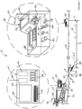
- Figure 1 illustrates one embodiment of a system for performing an inground operation, generally indicated by the reference number 10.
- the system includes a portable device 20 that is shown at a position on a surface 22 of the ground as well as in a further enlarged inset view. It is noted that inter-component cabling within device 20 has not been illustrated in order to maintain illustrative clarity, but is understood to be present and may readily be implemented by one having ordinary skill in the art in view of this overall disclosure.
- Device 20 includes a three-axis antenna cluster 26 measuring three orthogonally arranged components of magnetic flux indicated as b x , b y and b z .
- Antenna cluster 26 is electrically connected to a receiver section 32.
- a tilt sensor arrangement 34 may be provided for measuring gravitational angles from which the components of flux in a level coordinate system may be determined.
- Device 20 can further include a graphics display 36, a telemetry arrangement 38 having an antenna 40 and a processing section 42 interconnected appropriately with the various components.
- the processing section can include a digital signal processor (DSP) that is configured to execute various procedures that are needed during operation.
- DSP digital signal processor
- graphics display 36 can be a touch screen in order to facilitate operator selection of various buttons that are defined on the screen and/or scrolling can be facilitated between various buttons that are defined on the screen to provide for operator selection.
- Such a touch screen can be used alone or in combination with an input device 48 such as, for example, a keypad. The latter can be used without the need for a touch screen.
- many variations of the input device may be employed and can use scroll wheels and other suitable well-known forms of selection device.
- the processing section can include components such as, for example, one or more processors, memory of any appropriate type and analog to digital converters. As is well known in the art, the latter should be capable of detecting a frequency that is at least twice the frequency of the highest frequency of interest.
- a GPS (Global Positioning System) receiver 50 can be included along with a GPS antenna 52.
- the GPS components may be survey grade in order to provide enhanced position determination accuracy.
- Other components may be added as desired such as, for example, a magnetometer to aid in position determination relative to the drill direction and ultrasonic transducers for measuring the height of the device above the surface of the ground.
- device 20 can be selectively configured in two different ways with respect to providing a target for a boring tool 60 that emanates a locating field 62 such as, for example, a dipole electromagnetic signal.
- a target for a boring tool 60 that emanates a locating field 62 such as, for example, a dipole electromagnetic signal.
- device 20 itself serves as a target.
- device 20 can direct the boring tool to an offset target T that is located below the device.
- Both configurations are described, for example, in U.S. Patent no. 6,250,402 (hereinafter, the '402 patent), which is commonly owned with the present application , such that left/right ( ⁇ Y ) and up/down ( ⁇ Z ) steering commands can be generated to guide the boring tool to either the device or to the offset target.
- this arrangement determines a depth D of the boring tool and a horizontal distance S from the boring tool to the target, for example, in accordance with the '402 patent.
- U.S. Patent no. 6,727,704 which is commonly owned with the present application , brings to light still further advanced methods for generating steering commands and related information in which the location of the target is not constrained to being directly below the portable device. All of the information can be transmitted from telemetry antenna 40 of the device for use at a drill rig 70, as will be further described immediately hereinafter.
- the target position can correspond to a position along a predetermined bore plan (i.e., target path) 80 such as is described above, for example, with regard to the '951 patent.
- a portable device can utilize a joystick or other suitable mechanism that allows an operator of the portable device to directly generate drill rig actuation commands.
- a joystick or other suitable mechanism that allows an operator of the portable device to directly generate drill rig actuation commands.
- one such device is described in commonly owned U.S. Patent no. 6,079,506 (hereinafter, the '506 patent)
- handheld portable device 140 includes a joystick 148, as shown in Figures 3 and 4 of the '506 patent. Using such a joystick, any suitable set of drill rig actuation commands can be selectively issued to the operator at the drill rig.
- system 10 further includes drill rig 70 having a carriage 82 received for movement along the length of an opposing pair of rails 83.
- Boring tool 26 includes an asymmetric face 84 and is attached at an opposing end to a drill string 86.
- drill string 86 is made up of a plurality of removably attachable drill pipe sections such that the drill rig can force the drill string into the ground using movement in the direction of an arrow 88 and retract the drill string responsive to an opposite movement.
- the drill pipe sections can define a through passage for purposes of carrying a drilling mud or fluid that is emitted from the boring tool under pressure to assist in cutting through the ground as well as cooling the drill head.
- the drilling mud also serves to suspend and carry out cuttings to the surface along the exterior length of the drill string.
- Steering can be accomplished in a well known manner by orienting asymmetric face 84 such that the boring tool is deflected in a desired direction in the ground responsive to forward, push movement which can be referred to as a "push mode.”
- Rotation or spinning of the drill string by the drill rig will generally result in forward or straight advance of the boring tool which can be referred to as a "spin" or "advance" mode.
- the present example contemplates movement of the boring tool within a master XYZ coordinate system.
- the X axis can be at least generally coextensive with the surface of the ground and lie generally above an intended path of the boring tool, however, any other suitable arrangement of coordinate axes may be adopted.
- the origin of the master coordinate system is specified by reference numeral 90, essentially at the point where the boring tool enters the ground. While a Cartesian coordinate system is used as the basis for the master coordinate systems employed by the various embodiments which are disclosed herein, it is to be understood that this terminology is used for descriptive purposes and that any suitable coordinate system may be used.
- the X axis extends forward.
- the Y axis extends to the right when facing in the forward direction along the X axis and the Z axis is directed downward.
- the drilling operation is controlled by an operator (not shown) at a control console 100 (best seen in the enlarged inset view) which itself includes a telemetry receiver 102 connected with a telemetry antenna 104, a display screen 106, an input device such as a keyboard 110, a processing arrangement 112 which can include suitable interfaces and memory as well as one or more processors.
- a control console 100 which itself includes a telemetry receiver 102 connected with a telemetry antenna 104, a display screen 106, an input device such as a keyboard 110, a processing arrangement 112 which can include suitable interfaces and memory as well as one or more processors.
- the term display can be considered to encompass a suitable apparatus that is at least capable of illustrating embodiments of the various screen illustrations that are shown in the figures.
- a suitable apparatus includes console 100 and device 20 as well as any suitable display screen that is associated or driven by a suitable processing arrangement.
- a plurality of control levers 114 for example, control movement of carriage 82.
- screen 106 can
- device 20 receives signal 62 using antenna array 26 and processes the received signal, for example, in accordance with the above '402 patent to generate the ( ⁇ Y ) and ( ⁇ Z ) steering commands as well as depth D and distance S, all of which can be transmitted using a telemetry signal 120 to telemetry system 102 at the drill rig.
- locating signal 62 can be modulated in any suitable manner for purposes of carrying information to device 20.
- modulated information can include, by way of non-limiting example, orientation sensor readings such as pitch and roll orientation sensor readings, battery status, temperature, roll orientation, drilling mud pressure surrounding the boring tool and any other information of interest.
- console 100 can be provided remote from the drill rig, for example, as a portable/remote unit that includes drill rig actuation controls as well as display 106.
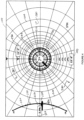
- Figures 2-4 are diagrammatic illustrations of the appearance of an embodiment of a target steering application as it can appear, for example, on display 106 of Figure 1 .
- illustrations of the appearance of the display have been limited to black and white line drawing as a result of the constraints imposed on figures presented in the context of a patent application and its requirements, however, full color may be used on the display in any suitable manner.
- At least some of the features of the target steering application will be described in terms of their potential appearance on a color display. Further, some features can involve progressive movement of elements of the display in the manner of animation, for example, to simulate a 3-D (three-dimensional) appearance.
- the display can include a series of concentric circles 200 sharing a center 202.
- Radial lines 204 can extend from center 202, for example, in 15 degree increments. Concentric circles 200 and radial lines 204 cooperate to simulate the appearance of a three dimensional tunnel, as will be further discussed.
- a target symbol 210 is also centered at 202 and can include cross-hairs 212 as well as an intersecting X shape formed within a circle 214. It is noted that the target symbol may be provided in a wide range of different configurations and is not limited to the described configuration.
- the target position can be established based on a signal from portable device 20 while, in other embodiments, the target position can be any suitable location along a predetermined target path.
- a pitch gauge 220 is presented near the left edge of display 106 and can present the most recent or current pitch value received at the drill rig.
- a value of 0.0% pitch is shown as the current pitch value in a pitch window 222 adjacent to a drill head symbol 224 which is centered on a pitch arc 230.
- the position of drill head symbol 224 on pitch arc 230 can be based on the current pitch value.
- the pitch value can range at least from -30 % to +30 %. Generally, it is relatively rare for drilling operations to use values outside of this range.
- Display 106 can present a current distance 240 from the target which corresponds to the current value of S, as described above.
- the current distance in the example of Figure 2 , is shown as 6.1m(20 feet), 0cm (0 inches).
- a series of chevrons can align to point in the direction of the target from the distance indication.
- Figure 2 involves the presentation of a roll/pitch gauge 260 on the display, offset from target center 202 in the context of instructing to the operator to re-orient or rotate the roll orientation of the boring tool prior to proceeding.
- the roll/pitch gauge may be referred to as a steering indicator.
- the illustration of Figure 2 can be considered as being representative of a rotate or roll command mode.
- the word "ROTATE" or other suitable textual indication can be displayed to convey the current actuation command, although this is not a requirement.
- the textual indication can be framed and/or presented using any suitable combination of color and/or animated graphical elements.
- a different display screen can be presented prior to the appearance of the screen of Figure 2 including a larger textual indication to emphasize to the operator that the actuation command is changing, as is likewise the case with other textual indications described below.
- the roll/pitch gauge in the present embodiment, is shown generally in the form of a clock face having 12 circumferential positions.
- a roll bar 262 can show the current roll orientation of the boring tool, for example, as decoded from telemetry signal 120 ( Figure 1 ).
- the current roll orientation can also be shown, for example, in a roll bubble 266 at the center of the clock face. In the present example, the current roll orientation is indicated as 12:00 o'clock.
- roll/pitch gauge 260 is angularly spaced and offset from center 202 in a way that is intended to intuitively demonstrate the current status of the boring tool, as uniquely represented by the roll/pitch gauge itself, relative to the target in terms of roll input that is needed from the operator.
- a graphical indication can be provided, for example, in the form of a caret 270 on the periphery of the roll/pitch gauge to indicate the angular orientation of the roll/pitch gauge with reference to the clock positions thereon. That is, the roll/pitch gauge is angularly offset from the target in a manner that is intended to represent the view that would be seen by the operator if the operator were able to look at least generally down the length of the drill string toward the target.
- the roll/pitch gauge graphically and numerically shows the current roll orientation of the boring tool to the operator.
- the roll/pitch gauge presentation described herein consolidates a significant amount of information into one convenient and easy to interpret view.
- the angular offset can be determined based on the inverse tangent of ( ⁇ Z / ⁇ Y ), the ratio of vertical steering command ⁇ Z to lateral steering command ⁇ Y wherein the steering commands are available via telemetry signal 120.
- a depth indication 274 can be provided in conjunction with the roll/pitch gauge to indicate the current depth of the boring tool as decoded from telemetry signal 120.
- the depth indication is shown in a window adjacent to a number of inverted chevrons that are spaced apart between the upper edge of the display and the upper periphery of the roll/pitch gauge. It should be appreciated that the depth indication and associated inverted chevrons move in concert with movement of the roll/pitch gauge around center 202, based on the steering commands.
- the display can call the attention of the operator to roll bar 262 in any suitable manner.
- the roll bar can be red in color, flash and/or be animated using some combination of features.
- caret 270 may exhibit the same behavior as the roll bar or any suitable behavior using color, animation and the like to indicate to the operator that a roll input is needed.
- Further indications can be provided to the operator, for example, based on the appearance and/or color of the clock face of the roll/pitch gauge.
- the clock face or some limited portion of the clock face can be shaded yellow or some variant thereof which can be maintained so long as roll bar 262 is not aligned with caret 270.
- Aural indication of the need for a roll input may also be provided. Responsive to this indication, the operator can rotate the drill string with the intention of aligning roll bar 262 with caret 270.
- the roll bar rotates around the roll/pitch gauge in a manner that will be described in further detail below.
- the position of the steering coordinator 260 can be established based on the magnitudes and signs of the X and Y steering commands.
- a roll indicator can be provided separate from the steering coordinator, for example, on a clock face that appears proximate to one corner of the display.
- Figure 2 further serves to introduce a pitch indicator 278 that extends across the clock face of the gauge.
- the pitch indicator can be referred to interchangeably as a pitch horizon. Since the current pitch reading in Figure 2 is zero degrees, the pitch indicator bisects the clock face. As will be seen in subsequent figures, the pitch indicator can move vertically on the roll/pitch gauge responsive to changes in the pitch orientation. Further, any suitable scheme can be used to define the current pitch reading, including, for example, color shading that defines a boundary corresponding to the proper location of the pitch horizon.
- Figure 3 demonstrates an embodiment of the appearance of display 106 responsive to the operator having rolled the drill string to bring roll bar 262 into alignment with caret 270 which indicates a push or advance command to the operator to push or advance the drill rod further into the ground without rotation.
- the word "PUSH" or other suitable textual indication can be displayed to convey the current actuation command, although this is not a requirement.
- the textual indication can be framed and/or presented using any suitable combination of color and/or animated graphical elements. If the operator misses the aligned condition, for example, due to wrap-up in the drill string, the operator can simply continue to rotate the drill string any number of revolutions until alignment is achieved.
- the color scheme can change.
- the roll bar and/or the caret can turn green and/or exhibit any suitable behavior such as, for example, flashing to indicate to the operator that the drill string should be advanced without rotation.
- the boring tool can then be advanced until indicated otherwise.
- the elements of display 106 can respond in a way that indicates to the operator that the boring tool is moving toward the target.
- circles 200 can expand in diameter as indicated by arrows 280.
- circles 200 can be animated to reduce in diameter responsive to retraction of the drill string.
- roll/pitch gauge 260 along with caret 270, can be positioned at any angular orientation that is defined in terms of the current steering command ratio.
- the result can be that it is not possible to achieve perfect alignment between the roll bar and caret.
- other indications such as color and/or animation can indicate to the operator that it is appropriate to advance the drill string despite some degree of misalignment between the roll bar and caret.
- a given transmitter generally includes a roll orientation sensor or sensing arrangement having a limited resolution.
- transmitters are available having 12 position (i.e., clock position) roll orientation sensing and 24 position (1/2 clock position) roll orientation sensing.
- clock position i.e., clock position
- 24 position 1/2 clock position
- progression of roll bar 262 around the roll/pitch gauge proceeds in a stepwise fashion from one sensed roll position to the next.
- the current sensed position can be rounded, based on the telemetry signal, to the nearest available roll orientation that can be indicated.
- roll/pitch gauge 260 and/or caret 270 can be positionally limited to angular orientations that correspond to or match positions that a given transmitter is capable of sensing by subjecting the current steering command ratio to rounding. Accordingly, roll/pitch gauge 260 and caret 270 can be located at uniformly spaced apart angular positions around center 202 that correspond to the roll orientations that can be indicated or sensed by the transmitter that is in use. In this way, each of the roll positions that can be indicated on roll/pitch gauge 262 can be brought into or achieve an aligned condition with caret 270.
- a display can be configured to illustrate a steering indicator in an offset positional relationship from a target indicator based on the steering commands such that the steering indicator graphically presents a modified desired steering direction.
- the modified steering direction is based on the desired steering direction such that when the desired steering direction falls between the predetermined spaced apart roll positions, the modified steering direction can correspond to a nearest one of the predetermined roll orientation positions to angularly align the modified steering direction with one of the predetermined spaced apart roll orientations.
- FIG. 4 an embodiment of the appearance of display 106 is illustrated responsive to the operator having steered the boring tool onto a direct path toward the target. That is, the boring tool should hit the target by spinning the drill string while pushing in the "spin" mode.
- the appearance of screen 106 in Figure 4 can be considered as providing a spin command to the operator.
- the word "SPIN" or other suitable textual indication can be displayed to convey the current actuation command, although this is not a requirement.
- the textual indication can be framed and/or presented using any suitable combination of color and/or animated graphical elements.
- the spin mode can be entered, for example, responsive to both steering commands ⁇ Y and ⁇ Z reducing to less than or equal to a selected threshold value.
- a suitable threshold value can be selected as a steering command of +/-5 units for a transmitter having a given range of 256 units for each steering command.
- the display can revert to either the rotate command or push command modes of Figures 2 and 3 , respectively.
- the display can toggle between the various command modes, as needed. It is noted that distance 240, to the target, is shown as having decreased to 4.57m(15 feet), 0cm (0 inches) while depth 274 is shown as having increased to 3.66m (12 feet), 0cm (0 inches).
- Drill head symbol 224 is shown at a position on pitch arc 230 that corresponds to the current pitch value of -2.5 percent which is likewise shown in pitch window 222.
- target symbol 210 can increase in size (i.e., diameter) while being centered within roll/pitch gauge 262.
- the latter can itself change in appearance.
- an outer ring 400 of the roll/pitch gauge can change in color relative to its appearance in the screens of Figures 2 and 3 such as, for example, transforming to a green circular band.
- Outer ring 400 can be animated, for example, to include rotating sections and/or color shading which rotation is indicated by an arrow 402 to demonstrate to the operator that rotation of the drill string is desired.
- caret 270 can disappear upon entering this display mode.
- Figure 4 additionally illustrates one embodiment of the appearance of pitch trending indicators 410a and 410b which can be referred to collectively using the reference number 410.
- minimum pitch indicator 410a specifies -2% while maximum pitch indicator 410b specifies +5%.
- the minimum and maximum values can be determined in any suitable manner.
- the minimum and maximum pitch value can be specified as corresponding values measured within some time period extending up to present time, for example, within the last ten seconds.
- the minimum and maximum pitch values can be selected from a predetermined number of the most recent pitch values such as, for example, the last thirty pitch readings.
- the pitch trending indicators can be indicative of drilling conditions.
- the pitch trend indicators when the boring tool is subject to a high degree of vibration, the pitch trend indicators generally will diverge from one another. Subject to relatively smooth operation, the pitch trend indicators generally will converge. In the event that the boring tool has been deflected responsive to striking an obstacle such as a rock, one of the pitch trending indications can correspond to the currently indicated pitch reading for the boring tool.
- the pitch trending indicators can also be useful, for example, to demonstrate that the bore is on-grade under circumstances when individual pitch readings can be quite variable.
- pitch information can also be provided as part of roll/pitch gauge 262.
- a "horizon" on the roll/pitch gauge can move vertically responsive to the current pitch reading such that the horizon bisects the roll/pitch gauge at zero pitch, moves up as pitch becomes more negative and moves down as pitch becomes more positive. Any suitable scheme can be used to define the pitch horizon, including, for example, color shading.
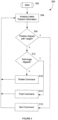
- Figure 5 is a flow diagram, generally indicated by the reference number 500, which illustrates an embodiment for the operation of the target steering application according to the present disclosure.
- the method begins at 502 and proceeds to 504 which analyzes the most recent boring tool position and related information received, for example, via telemetry signal 120. In some embodiments, at least some information such as, for example, sensor-based orientation readings, may be received at the drill rig via data transmission that utilizes the drill string.
- a test determines whether the boring tool is aligned with the target. Such a determination can be based, for example, on the magnitudes of the steering commands in view of a threshold value, as discussed above.
- Alignment can be determined on the basis of the angular resolution provided by the steering commands in view of the number of roll positions that can be detected by a given transmitter. For example, the steering commands can be rounded to the nearest roll orientation that can be detected/indicated by the given transmitter. If the boring tool is aligned, operation proceeds to 510 such that display 106 can issue the spin command, for example, based on its appearance in Figure 4 . On the other hand, if the boring tool is not aligned with the target, operation next proceeds to an appropriate one of the rotate command ( Figure 2 ) or the push command ( Figure 3 ).
- step 512 tests whether the current roll orientation angle of the boring tool is aligned with the direction in which steering is needed based on the steering command ratio in a manner that is consistent with presentation of the push command, for example, as seen in Figure 3 .
- the steering commands can be rounded to the nearest roll orientation that can be indicated by a given transmitter. If alignment is appropriate, operation proceeds to 514 such that the push command screen of Figure 3 or its equivalent can be presented to the operator. If alignment is not appropriate, operation proceeds to 518 such that the rotate command screen of Figure 2 or its equivalent can be presented to the operator. Subsequent to each of spin command 510, push command 514 and rotate command 518, operation returns to 504. The described process can repeat in an iterative manner until the boring tool arrives at the target.
- Iterations of the process can be performed at any suitable rate for purposes of updating the display.
- the iteration rate can be based on the rotation rate of the drill string.
- iterations can be performed at a rapid rate which is limited by constraints that are imposed by system hardware. For example, an iteration can be performed each time that a roll update is received from the inground transmitter electronics.
- roll/pitch gauge 260 can be presented on display 106 as part of an overall target steering display, as seen in Figures 2-4 , or individually on display 106, as seen in Figure 6 and/or on display 36 of device 20.
- the appearance of the roll/pitch gauge can be identical in either case, however, at least certain features admit of greater illustrative clarity using independent views of the roll/pitch gauge, the largest of which is the subject of the present discussion.
- roll/pitch gauge 260 corresponds at least generally to its appearance in Figure 2 including roll bubble 266 indicating a 12:00 o'clock roll indication having roll bar 262 aligned at the 12:00 o'clock position. While the roll bar is shown as being transparent to illustrate the underlying clock face, the roll bar can be of any suitable color and may block the view of the clock face therebeneath.
- a transition zone or region 602 above the location of pitch indicator 278 and having an upper boundary defined by a dashed line 604, can be progressively shaded, for example, from white proximate to the pitch indicator location to a golden hue at the top margin of the region that fades out almost entirely upon reaching upper boundary 604.
- An upper portion 610 of the clock face can be of a different color such as, for example, blue.
- the proportion of each of the different color regions on the clock face of the roll/pitch gauge can change responsive to changes in the pitch angle.
- Region 602 can move vertically in concert with movement of pitch indicator 278. The vertical width of region 602 can change responsive to the current pitch value.
- the region can become more narrow vertically. Conversely, as the pitch increases in the negative direction, the region can broaden vertically or remain unchanged.
- Numerical indications can be provided for selected positions on the clock face, for example, as shown. Color schemes can be selected to maintain visibility of roll bubble 266 in embodiments that apply shading to the roll bubble based on the colors applied to regions 600, 602 and 610.
- Figure 7 presents embodiments of the appearance of the roll/pitch gauge on display 106 for increasingly positive pitch values, designated by the reference numbers 700a-f, each of which is captioned with the illustrated pitch value and the indicated roll value. It should be appreciated that the various regions described above with reference to Figure 6 can readily be provided for each of these screenshots.
- the location of the pitch indicator line can be determined for a standard coordinate system by taking the negative of the current pitch value in degrees and then multiplying by a constant that is based at least in part on the height of the gauge.
- Figure 8 presents embodiments of the appearance of the roll/pitch gauge on display 106 for increasingly negative pitch values, designated by the reference numbers 800a-f, each of which is captioned with the illustrated pitch value and the indicated roll value. It should be appreciated that the various regions described above with reference to Figure 6 can readily be provided for each of these screenshots.
- data is received which can include pitch data and roll data.
- data can be received via telemetry and/or in any other suitable manner such as by transmission from the boring tool up to the drill rig via the drill string.
- the received data is decoded and can be transferred at 904 to a data store.
- the latter for example, can be located in memory at console 100 on the drill rig.
- New pitch data is then used at 906 for adjusting the pitch indications as reflected by pitch gauge 220 ( Figures 2-4 ), pitch trending indicators (410a and 410b in Figure 4 ) and the roll/pitch gauges seen in Figures 2-4 and 5-8 .
- New roll data can likewise be used at 910 for adjusting the roll indications as reflected by the roll/pitch gauges seen in Figures 2-4 and 5-8 . Subsequent to steps 906 and 910, operation returns to 902 and can proceed in this loop throughout the operation of the system.
- FIG 10 is a diagrammatic illustration of the appearance of another embodiment of a target steering application as it can appear, for example, on display 106 of Figure 1 . It is noted that descriptions of some like components have not been repeated for purposes of brevity.
- the center of concentric circles 200 is centered upon roll gauge 260 with target symbol 210' being movable relative to the roll gauge (i.e., steering indicator 260) such that the frame of reference is reversed as compared to Figures 2-4 . That is, the target symbol moves around the centered roll gauge in Figure 10 based on the steering commands.
- Radial lines 204 extend from the center of the roll gauge, for example, in 15 degree increments.
- Concentric circles 200 and radial lines 204 can continue to cooperate to simulate the appearance of a three dimensional tunnel with similar animations applied to circles 200 responsive to forward and reverse movement of the boring tool.
- Target symbol 210' can include an intersecting X shape formed within circle 214. It is noted that the target symbol may be provided in a wide range of different configurations and is not limited to the described configuration.
- the target symbol moves relative to the center of circles 200 based on the steering commands during an ongoing drilling operation. In an embodiment, the relative size of the target symbol can change responsive to distance of the boring tool from the actual target position, as described above.
- Pitch gauge 220 is presented near the left edge of display 106 and can present the most recent or current pitch value received at the drill rig.
- a value of 0.0% pitch is shown as the current pitch value.
- Current distance 240 from the target is shown as 4.57m(15 feet), 0cm (0 inches), while in current depth indication 274 shows a depth of 3.66m (12 feet), 0cm (0 inches) for the boring tool.
- a series of chevrons can align to point in the direction of the roll gauge from the distance indication.
- a series of hexagons 1000 leads from roll gauge 260 to target 210'.
- the diameter of each hexagon in the series can progressively decrease in size with increasing distance from the roll gauge/boring tool.
- the angular orientation of each hexagon in the series can be determined based on the curvature of the drill string at an associated point on the drill path. In this way, the display intuitively illustrates 3-D curvature along the path.
- the use of hexagons is not intended as being limiting, any suitable symbol or symbols may be employed as representative of the drill path ahead.
- the drill path and its associated curvature can be established in any suitable manner such as, for example, based on a pre-planned intended path that is determined prior to drilling or determined on-the-fly.
- FIG. 10 is analogous to the illustration of Figure 2 by way of illustrating a rotate command.
- color schemes and/or animation can be utilized in a manner that is consistent with the descriptions above and with a great deal of flexibility while continuing to remain within the scope of the teachings that have been brought to light herein.
- One of ordinary skill in the art can readily implement a display corresponding to the push command of Figure 3 having this overall disclosure in hand.
- a rotate command and/or push command consistent with Figure 10 can readily be used in conjunction with the spin command of Figure 4 , to form the full set of commands, since the target and steering indicators are aligned for purposes of the spin command.
- actuation commands can be communicated to the operator in any suitable manner.
- embodiments can utilize aural actuation commands, touch-based haptic actuation commands, resistance of drill rig controls such as, for example, control levers to operator actuations, vibration of drill rig controls to indicate appropriate and/or inappropriate controls for a particular actuation command or any suitable combinations thereof, including combinations that utilize a visual display.
- a display is configured to selectively and automatically provide indications as drill rig actuation commands to an operator including each of a rotate command, a push command and a spin command responsive at least in part to the steering commands.
- actuation command set can be customized in any desired way, for example, based on one or more of the actuation commands described herein, other actuation commands and/or any suitable combination of actuation commands.
- the display can issue an appropriate one of the drill rig actuation commands. That is, the operator can always rely on the presence of guidance in the form of the current drill rig actuation command.
- the display can consolidate relevant information such as, for example, the current roll orientation of the boring tool into a steering indicator to provide an intuitive representation of the actual operational status of the drill rig and boring tool integral with and in view of the current drill rig actuation command. Moreover, the need for the operator to interpret or translate steering commands in conjunction with other information such as, for example, the current roll orientation of the boring tool to formulate appropriate drill rig actuations is effectively eliminated.
Landscapes
- Engineering & Computer Science (AREA)
- Mining & Mineral Resources (AREA)
- Geology (AREA)
- Life Sciences & Earth Sciences (AREA)
- Physics & Mathematics (AREA)
- Geochemistry & Mineralogy (AREA)
- Fluid Mechanics (AREA)
- General Life Sciences & Earth Sciences (AREA)
- Environmental & Geological Engineering (AREA)
- Mechanical Engineering (AREA)
- Geophysics (AREA)
- General Engineering & Computer Science (AREA)
- Civil Engineering (AREA)
- Structural Engineering (AREA)
- Earth Drilling (AREA)
- Operations Research (AREA)
Claims (13)
- Appareil dans un système (10) pour réaliser un forage directionnel horizontal comprenant un train de tiges de forage (86) s'étendant d'une installation de forage (70) à un outil de forage (60) de sorte que l'outil de forage (60) puisse être orienté en fonction de son orientation de giration, ledit système (10) comprenant un agencement pour générer des commandes d'orientation pour guider l'outil de forage (60) jusqu'à une position cible ; lesdites commandes d'orientation comprenant une commande d'orientation verticale et une commande d'orientation horizontale de sorte qu'un rapport de commande d'orientation entre la commande d'orientation verticale et la commande d'orientation horizontale définisse une direction d'orientation souhaitée pour guider l'outil de forage vers la cible ; ledit appareil comprenant :
un écran (106) conçu pour, en réponse au moins en partie auxdites commandes d'orientation, fournir sélectivement et automatiquement des commandes d'actionnement d'installation de forage à un opérateur, y compris chacune parmi une commande de rotation, une commande de poussée et une commande de vissage ; la commande de poussée et la commande de rotation réagissant en outre à ladite orientation de giration de l'outil de forage. - Appareil selon la revendication 1, l'écran (106) étant conçu pour indiquer visuellement à un opérateur chacune parmi ladite commande de rotation, ladite commande de poussée et ladite commande de vissage.
- Appareil selon la revendication 1, l'écran (106) illustrant un indicateur d'orientation qui est positionné sur l'écran en fonction des commandes d'orientation et l'indicateur d'orientation indiquant ladite orientation de giration de l'outil de forage.
- Appareil selon la revendication 3, l'indicateur d'orientation indiquant graphiquement l'orientation de giration sur un cadran d'horloge.
- Appareil selon la revendication 3, l'indicateur d'orientation indiquant numériquement l'orientation de giration.
- Appareil selon la revendication 1, l'affichage (106) étant conçu pour basculer entre l'indication de la commande de vissage et chacune de la commande de poussée et de la commande de rotation en fonction d'une valeur de seuil de l'amplitude de chacune de la commande d'orientation verticale et de la commande d'orientation horizontale.
- Appareil selon la revendication 6, l'amplitude de chacune de la commande de poussée et de la commande de rotation étant spécifiée dans une plage de 256 unités et la valeur de seuil étant inférieure ou égale à 5 unités.
- Appareil selon la revendication 6, l'écran (106) illustrant un indicateur d'orientation qui est conçu pour changer d'aspect lorsque la commande de rotation est émise par rapport aux aspects de la commande de poussée et de la commande de vissage.
- Appareil selon la revendication 8, l'indicateur d'orientation étant conçu pour inclure un premier diamètre correspondant à la commande de poussée et à la commande de vissage et un second diamètre plus grand correspondant à la commande de rotation.
- Appareil selon la revendication 9, l'écran (106) illustrant un indicateur de cible et ledit écran (106) étant conçu pour centrer l'indicateur d'orientation sur l'indicateur de cible lorsque la commande d'orientation verticale et la commande d'orientation horizontale satisfont toutes deux à ladite valeur de seuil.
- Appareil selon la revendication 1, la position cible étant définie en relation fixe par rapport à un dispositif portable (140) qui transmet un signal de localisation.
- Appareil selon la revendication 1, la position cible étant un point le long d'un plan de forage prédéfini.
- Procédé destiné à être utilisé dans un système (10) pour réaliser un forage directionnel horizontal comprenant un train de tiges de forage (86) s'étendant d'une installation de forage (70) à un outil de forage (60) de sorte que l'outil de forage (60) puisse être orienté en fonction de son orientation de giration, ledit système (10) comprenant un agencement pour générer des commandes d'orientation pour guider l'outil de forage (60) jusqu'à une position cible ; lesdites commandes d'orientation comprenant une commande d'orientation verticale et une commande d'orientation horizontale de sorte qu'un rapport de commande d'orientation entre la commande d'orientation verticale et la commande d'orientation horizontale définit une direction d'orientation souhaitée pour guider l'outil de forage vers la cible ; ledit procédé comprenant l'étape consistant à :
fournir sélectivement et automatiquement des commandes d'actionnement d'installation de forage à un opérateur, y compris chacune parmi une commande de rotation, une commande de poussée et une commande de vissage en réponse au moins en partie auxdites commandes d'orientation ; la commande de poussée et la commande de rotation répondant en outre à ladite orientation de giration de l'outil de forage.
Applications Claiming Priority (3)
| Application Number | Priority Date | Filing Date | Title |
|---|---|---|---|
| US201261583566P | 2012-01-05 | 2012-01-05 | |
| US13/725,718 US9540879B2 (en) | 2012-01-05 | 2012-12-21 | Directional drilling target steering apparatus and method |
| PCT/US2013/020128 WO2013103706A1 (fr) | 2012-01-05 | 2013-01-03 | Appareil et procédé d'orientation cible de forage directionnel |
Publications (4)
| Publication Number | Publication Date |
|---|---|
| EP2802739A1 EP2802739A1 (fr) | 2014-11-19 |
| EP2802739A4 EP2802739A4 (fr) | 2016-06-22 |
| EP2802739C0 EP2802739C0 (fr) | 2023-08-30 |
| EP2802739B1 true EP2802739B1 (fr) | 2023-08-30 |
Family
ID=48743144
Family Applications (1)
| Application Number | Title | Priority Date | Filing Date |
|---|---|---|---|
| EP13733668.1A Active EP2802739B1 (fr) | 2012-01-05 | 2013-01-03 | Appareil et procédé d'orientation cible de forage directionnel |
Country Status (6)
| Country | Link |
|---|---|
| US (5) | US9540879B2 (fr) |
| EP (1) | EP2802739B1 (fr) |
| CN (1) | CN104053856B (fr) |
| HK (1) | HK1202140A1 (fr) |
| RU (1) | RU2600118C2 (fr) |
| WO (1) | WO2013103706A1 (fr) |
Families Citing this family (34)
| Publication number | Priority date | Publication date | Assignee | Title |
|---|---|---|---|---|
| WO2008039523A1 (fr) | 2006-09-27 | 2008-04-03 | Halliburton Energy Services, Inc. | Surveillance et contrôle d'opérations et simulations de forage dirigé |
| US8729901B2 (en) | 2009-07-06 | 2014-05-20 | Merlin Technology, Inc. | Measurement device and associated method for use in frequency selection for inground transmission |
| US9026242B2 (en) | 2011-05-19 | 2015-05-05 | Taktia Llc | Automatically guided tools |
| US9297205B2 (en) | 2011-12-22 | 2016-03-29 | Hunt Advanced Drilling Technologies, LLC | System and method for controlling a drilling path based on drift estimates |
| US11085283B2 (en) | 2011-12-22 | 2021-08-10 | Motive Drilling Technologies, Inc. | System and method for surface steerable drilling using tactical tracking |
| US8210283B1 (en) | 2011-12-22 | 2012-07-03 | Hunt Energy Enterprises, L.L.C. | System and method for surface steerable drilling |
| US8596385B2 (en) | 2011-12-22 | 2013-12-03 | Hunt Advanced Drilling Technologies, L.L.C. | System and method for determining incremental progression between survey points while drilling |
| US9540879B2 (en) * | 2012-01-05 | 2017-01-10 | Merlin Technology, Inc. | Directional drilling target steering apparatus and method |
| JP6301314B2 (ja) | 2012-04-26 | 2018-03-28 | シェイパー ツールズ, インク.Shaper Tools, Inc. | 材料に作業を実行するため又は材料の表面に対する装置の位置を特定するためのシステム及び方法 |
| EP2971489B1 (fr) * | 2013-03-13 | 2019-05-15 | Halliburton Energy Services, Inc. | Surveillance et commande d'opérations et simulation de forage directionnel |
| JP6147037B2 (ja) | 2013-03-14 | 2017-06-14 | 株式会社トプコン | 建設機械制御システム |
| CN103846558B (zh) * | 2014-02-19 | 2016-04-13 | 昆山市正业电子有限公司 | 一种pcb板的钻孔分块方法 |
| US11106185B2 (en) | 2014-06-25 | 2021-08-31 | Motive Drilling Technologies, Inc. | System and method for surface steerable drilling to provide formation mechanical analysis |
| US9739140B2 (en) | 2014-09-05 | 2017-08-22 | Merlin Technology, Inc. | Communication protocol in directional drilling system, apparatus and method utilizing multi-bit data symbol transmission |
| EP3657279B1 (fr) | 2015-05-13 | 2023-03-29 | Shaper Tools, Inc. | Systèmes, procédés et appareil pour outils guidés |
| US9759012B2 (en) | 2015-09-24 | 2017-09-12 | Merlin Technology, Inc. | Multimode steering and homing system, method and apparatus |
| CN106639875B (zh) * | 2015-10-30 | 2018-11-16 | 中石化石油工程技术服务有限公司 | 一种旋转导向测控系统实验装置 |
| US20170122095A1 (en) * | 2015-11-03 | 2017-05-04 | Ubiterra Corporation | Automated geo-target and geo-hazard notifications for drilling systems |
| US11151762B2 (en) | 2015-11-03 | 2021-10-19 | Ubiterra Corporation | Systems and methods for shared visualization and display of drilling information |
| US11512534B2 (en) * | 2016-02-05 | 2022-11-29 | The Charles Machine Works, Inc. | Method for guiding a downhole tool underground |
| KR101838187B1 (ko) * | 2016-03-25 | 2018-04-26 | 엘지전자 주식회사 | 디스플레이 장치 및 이를 포함하는 차량 |
| US10589626B2 (en) | 2016-06-20 | 2020-03-17 | Caterpillar Inc. | Implement positioning guidance system |
| USD800764S1 (en) | 2016-06-20 | 2017-10-24 | Caterpillar Inc. | Display screen or portion thereof with set of icons |
| EP3500894B1 (fr) | 2016-08-19 | 2024-05-15 | Shaper Tools, Inc. | Appareil et procédé pour guider un outil placé sur la surface d'un matériau |
| US11933158B2 (en) | 2016-09-02 | 2024-03-19 | Motive Drilling Technologies, Inc. | System and method for mag ranging drilling control |
| CN106594386B (zh) * | 2016-12-23 | 2019-03-01 | 中石化石油工程设计有限公司 | 一种非开挖钻顶联合穿跨越管道铺设方法 |
| US10890030B2 (en) * | 2016-12-28 | 2021-01-12 | Xr Lateral Llc | Method, apparatus by method, and apparatus of guidance positioning members for directional drilling |
| US10378338B2 (en) | 2017-06-28 | 2019-08-13 | Merlin Technology, Inc. | Advanced passive interference management in directional drilling system, apparatus and methods |
| US11397266B2 (en) | 2018-08-29 | 2022-07-26 | Subsite, Llc | GPS assisted walkover locating system and method |
| CN109403946B (zh) * | 2018-12-27 | 2022-07-29 | 北京三一智造科技有限公司 | 旋挖钻机回转动画显示的方法、装置及旋挖钻机 |
| USD914706S1 (en) | 2019-06-28 | 2021-03-30 | The Charles Machine Works, Inc. | Display screen with graphical user interface |
| US11149539B2 (en) | 2019-07-23 | 2021-10-19 | Merlin Technology, Inc. | Drill planning tool for topography characterization, system and associated methods |
| US11933156B2 (en) * | 2020-04-28 | 2024-03-19 | Schlumberger Technology Corporation | Controller augmenting existing control system |
| TR202014907A2 (tr) * | 2020-09-18 | 2020-12-21 | Beta Elektronik Otomasyon Makina San Vetic Ltd Sti | Sabi̇t taşinabi̇li̇r kesi̇ci̇ deli̇ci̇ elektri̇kli̇ maki̇nalarin doğrusal çalişmasina yardimci üni̇te |
Citations (1)
| Publication number | Priority date | Publication date | Assignee | Title |
|---|---|---|---|---|
| US6250402B1 (en) * | 1997-04-16 | 2001-06-26 | Digital Control Incorporated | Establishing positions of locating field detectors and path mappings in underground boring tool applications |
Family Cites Families (27)
| Publication number | Priority date | Publication date | Assignee | Title |
|---|---|---|---|---|
| US5419405A (en) * | 1989-12-22 | 1995-05-30 | Patton Consulting | System for controlled drilling of boreholes along planned profile |
| US5155442A (en) * | 1991-03-01 | 1992-10-13 | John Mercer | Position and orientation locator/monitor |
| US5337002A (en) * | 1991-03-01 | 1994-08-09 | Mercer John E | Locator device for continuously locating a dipole magnetic field transmitter and its method of operation |
| US6035951A (en) | 1997-04-16 | 2000-03-14 | Digital Control Incorporated | System for tracking and/or guiding an underground boring tool |
| US6079506A (en) | 1998-04-27 | 2000-06-27 | Digital Control Incorporated | Boring tool control using remote locator |
| AU756936B2 (en) | 1999-01-13 | 2003-01-30 | Kevin L. Alft | Automated bore planning method and apparatus for horizontal directional drilling |
| US6308787B1 (en) | 1999-09-24 | 2001-10-30 | Vermeer Manufacturing Company | Real-time control system and method for controlling an underground boring machine |
| US6408952B1 (en) | 1999-12-17 | 2002-06-25 | Vermeer Manufacturing Company | Remote lock-out system and method for a horizontal direction drilling system |
| US6496008B1 (en) | 2000-08-17 | 2002-12-17 | Digital Control Incorporated | Flux plane locating in an underground drilling system |
| JP4450352B2 (ja) | 2001-09-10 | 2010-04-14 | ライト工業株式会社 | 削孔管理プログラム及び削孔管理装置 |
| US6727704B2 (en) | 2001-11-20 | 2004-04-27 | Marlin Technology, Inc. | Boring tool tracking/guiding system and method with unconstrained target location geometry |
| US7000710B1 (en) | 2002-04-01 | 2006-02-21 | The Charles Machine Works, Inc. | Automatic path generation and correction system |
| RU2215874C1 (ru) | 2002-05-20 | 2003-11-10 | Закрытое акционерное общество Научно-производственная фирма "Самарские Горизонты" | Автоматизированный навигационный буровой комплекс для прокладки коммуникаций |
| US6868921B2 (en) | 2003-01-13 | 2005-03-22 | Merlin Technology, Inc. | Boring tool tracking fundamentally based on drill string length, pitch and roll |
| US7630872B2 (en) | 2004-09-16 | 2009-12-08 | Schlumberger Technology Corporation | Methods for visualizing distances between wellbore and formation boundaries |
| DE102007003080B4 (de) | 2006-01-17 | 2018-02-08 | Vermeer Manufacturing Comp. | Unterirdische Bohrmaschine und Verfahren zum Steuern des unterirdischen Bohrens |
| US7404454B2 (en) * | 2006-05-05 | 2008-07-29 | Varco I/P, Inc. | Bit face orientation control in drilling operations |
| WO2008039523A1 (fr) * | 2006-09-27 | 2008-04-03 | Halliburton Energy Services, Inc. | Surveillance et contrôle d'opérations et simulations de forage dirigé |
| US7952357B2 (en) | 2007-09-28 | 2011-05-31 | The Charles Machines Works, Inc. | Receiver system for determining the location of a magnetic field source |
| RU2439315C1 (ru) | 2007-12-21 | 2012-01-10 | Кэнриг Дриллинг Текнолоджи Лтд. | Интегрированное отображение положения ведущего переводника и ориентации торца долота |
| US8473166B2 (en) * | 2009-05-19 | 2013-06-25 | Topcon Positioning Systems, Inc. | Semiautomatic control of earthmoving machine based on attitude measurement |
| US8381836B2 (en) * | 2010-01-19 | 2013-02-26 | Merlin Technology Inc. | Advanced underground homing system, apparatus and method |
| CN101864943A (zh) | 2010-06-09 | 2010-10-20 | 宁波金地电子有限公司 | 非开挖导向控制设备及方法 |
| US8210283B1 (en) * | 2011-12-22 | 2012-07-03 | Hunt Energy Enterprises, L.L.C. | System and method for surface steerable drilling |
| US8596385B2 (en) * | 2011-12-22 | 2013-12-03 | Hunt Advanced Drilling Technologies, L.L.C. | System and method for determining incremental progression between survey points while drilling |
| US9540879B2 (en) * | 2012-01-05 | 2017-01-10 | Merlin Technology, Inc. | Directional drilling target steering apparatus and method |
| US9428961B2 (en) * | 2014-06-25 | 2016-08-30 | Motive Drilling Technologies, Inc. | Surface steerable drilling system for use with rotary steerable system |
-
2012
- 2012-12-21 US US13/725,718 patent/US9540879B2/en active Active
-
2013
- 2013-01-03 CN CN201380004747.8A patent/CN104053856B/zh active Active
- 2013-01-03 EP EP13733668.1A patent/EP2802739B1/fr active Active
- 2013-01-03 WO PCT/US2013/020128 patent/WO2013103706A1/fr active Application Filing
- 2013-01-03 RU RU2014126088/03A patent/RU2600118C2/ru active
-
2015
- 2015-03-17 HK HK15102699.3A patent/HK1202140A1/xx unknown
-
2016
- 2016-12-08 US US15/373,417 patent/US10781638B2/en active Active
-
2020
- 2020-08-16 US US16/994,619 patent/US11060355B2/en active Active
-
2021
- 2021-07-12 US US17/373,553 patent/US11629554B2/en active Active
-
2023
- 2023-04-13 US US18/134,542 patent/US20230250693A1/en active Pending
Patent Citations (1)
| Publication number | Priority date | Publication date | Assignee | Title |
|---|---|---|---|---|
| US6250402B1 (en) * | 1997-04-16 | 2001-06-26 | Digital Control Incorporated | Establishing positions of locating field detectors and path mappings in underground boring tool applications |
Also Published As
| Publication number | Publication date |
|---|---|
| US11629554B2 (en) | 2023-04-18 |
| US20210340819A1 (en) | 2021-11-04 |
| CN104053856A (zh) | 2014-09-17 |
| CN104053856B (zh) | 2018-04-17 |
| US11060355B2 (en) | 2021-07-13 |
| US20230250693A1 (en) | 2023-08-10 |
| US20130175092A1 (en) | 2013-07-11 |
| EP2802739C0 (fr) | 2023-08-30 |
| HK1202140A1 (en) | 2015-11-13 |
| US10781638B2 (en) | 2020-09-22 |
| RU2014126088A (ru) | 2016-01-27 |
| US20170089139A1 (en) | 2017-03-30 |
| RU2600118C2 (ru) | 2016-10-20 |
| EP2802739A4 (fr) | 2016-06-22 |
| US9540879B2 (en) | 2017-01-10 |
| WO2013103706A1 (fr) | 2013-07-11 |
| US20200378189A1 (en) | 2020-12-03 |
| EP2802739A1 (fr) | 2014-11-19 |
Similar Documents
| Publication | Publication Date | Title |
|---|---|---|
| US11629554B2 (en) | Directional drilling target steering apparatus and method | |
| US10672154B2 (en) | 3D toolface wellbore steering visualization | |
| US6856135B2 (en) | Boring tool tracking/guiding system and method with unconstrained target location geometry | |
| US9290995B2 (en) | Drill string oscillation methods | |
| EP2191096B1 (fr) | Dispositifs et procédés pour reconfiguration de procédures de forage dynamique | |
| US10961837B2 (en) | Downhole 3D geo steering viewer for a drilling apparatus | |
| US10794169B2 (en) | Systems, devices, and methods for generating drilling windows | |
| CN107109928B (zh) | 用于多模式转向和归位系统的装置和方法 | |
| US9657521B2 (en) | Directional system drilling and method | |
| US11136882B2 (en) | Automated drilling instructions for steerable drilling systems | |
| EP3877955A1 (fr) | Affichage de fond de trou | |
| US20200116010A1 (en) | Devices, Systems and Methods to Calculate Slide Stability | |
| US11512577B2 (en) | Steerable drilling bi-directional communications system and methods | |
| AU2023241290A1 (en) | Mobility control for mobile drilling rig |
Legal Events
| Date | Code | Title | Description |
|---|---|---|---|
| PUAI | Public reference made under article 153(3) epc to a published international application that has entered the european phase |
Free format text: ORIGINAL CODE: 0009012 |
|
| 17P | Request for examination filed |
Effective date: 20140801 |
|
| AK | Designated contracting states |
Kind code of ref document: A1 Designated state(s): AL AT BE BG CH CY CZ DE DK EE ES FI FR GB GR HR HU IE IS IT LI LT LU LV MC MK MT NL NO PL PT RO RS SE SI SK SM TR |
|
| DAX | Request for extension of the european patent (deleted) | ||
| RA4 | Supplementary search report drawn up and despatched (corrected) |
Effective date: 20160520 |
|
| RIC1 | Information provided on ipc code assigned before grant |
Ipc: E21B 44/00 20060101ALI20160513BHEP Ipc: E21B 7/04 20060101ALI20160513BHEP Ipc: E02F 5/18 20060101ALI20160513BHEP Ipc: E21B 47/02 20060101AFI20160513BHEP |
|
| STAA | Information on the status of an ep patent application or granted ep patent |
Free format text: STATUS: EXAMINATION IS IN PROGRESS |
|
| 17Q | First examination report despatched |
Effective date: 20170329 |
|
| STAA | Information on the status of an ep patent application or granted ep patent |
Free format text: STATUS: EXAMINATION IS IN PROGRESS |
|
| APBK | Appeal reference recorded |
Free format text: ORIGINAL CODE: EPIDOSNREFNE |
|
| APBN | Date of receipt of notice of appeal recorded |
Free format text: ORIGINAL CODE: EPIDOSNNOA2E |
|
| APBR | Date of receipt of statement of grounds of appeal recorded |
Free format text: ORIGINAL CODE: EPIDOSNNOA3E |
|
| APAF | Appeal reference modified |
Free format text: ORIGINAL CODE: EPIDOSCREFNE |
|
| APBX | Invitation to file observations in appeal sent |
Free format text: ORIGINAL CODE: EPIDOSNOBA2E |
|
| APBZ | Receipt of observations in appeal recorded |
Free format text: ORIGINAL CODE: EPIDOSNOBA4E |
|
| APBT | Appeal procedure closed |
Free format text: ORIGINAL CODE: EPIDOSNNOA9E |
|
| GRAP | Despatch of communication of intention to grant a patent |
Free format text: ORIGINAL CODE: EPIDOSNIGR1 |
|
| STAA | Information on the status of an ep patent application or granted ep patent |
Free format text: STATUS: GRANT OF PATENT IS INTENDED |
|
| INTG | Intention to grant announced |
Effective date: 20230322 |
|
| GRAS | Grant fee paid |
Free format text: ORIGINAL CODE: EPIDOSNIGR3 |
|
| GRAA | (expected) grant |
Free format text: ORIGINAL CODE: 0009210 |
|
| STAA | Information on the status of an ep patent application or granted ep patent |
Free format text: STATUS: THE PATENT HAS BEEN GRANTED |
|
| AK | Designated contracting states |
Kind code of ref document: B1 Designated state(s): AL AT BE BG CH CY CZ DE DK EE ES FI FR GB GR HR HU IE IS IT LI LT LU LV MC MK MT NL NO PL PT RO RS SE SI SK SM TR |
|
| REG | Reference to a national code |
Ref country code: GB Ref legal event code: FG4D |
|
| REG | Reference to a national code |
Ref country code: CH Ref legal event code: EP |
|
| REG | Reference to a national code |
Ref country code: DE Ref legal event code: R096 Ref document number: 602013084536 Country of ref document: DE |
|
| REG | Reference to a national code |
Ref country code: IE Ref legal event code: FG4D |
|
| U01 | Request for unitary effect filed |
Effective date: 20230906 |
|
| U07 | Unitary effect registered |
Designated state(s): AT BE BG DE DK EE FI FR IT LT LU LV MT NL PT SE SI Effective date: 20230913 |
|
| PG25 | Lapsed in a contracting state [announced via postgrant information from national office to epo] |
Ref country code: GR Free format text: LAPSE BECAUSE OF FAILURE TO SUBMIT A TRANSLATION OF THE DESCRIPTION OR TO PAY THE FEE WITHIN THE PRESCRIBED TIME-LIMIT Effective date: 20231201 |
|
| PG25 | Lapsed in a contracting state [announced via postgrant information from national office to epo] |
Ref country code: IS Free format text: LAPSE BECAUSE OF FAILURE TO SUBMIT A TRANSLATION OF THE DESCRIPTION OR TO PAY THE FEE WITHIN THE PRESCRIBED TIME-LIMIT Effective date: 20231230 |
|
| PG25 | Lapsed in a contracting state [announced via postgrant information from national office to epo] |
Ref country code: RS Free format text: LAPSE BECAUSE OF FAILURE TO SUBMIT A TRANSLATION OF THE DESCRIPTION OR TO PAY THE FEE WITHIN THE PRESCRIBED TIME-LIMIT Effective date: 20230830 Ref country code: NO Free format text: LAPSE BECAUSE OF FAILURE TO SUBMIT A TRANSLATION OF THE DESCRIPTION OR TO PAY THE FEE WITHIN THE PRESCRIBED TIME-LIMIT Effective date: 20231130 Ref country code: IS Free format text: LAPSE BECAUSE OF FAILURE TO SUBMIT A TRANSLATION OF THE DESCRIPTION OR TO PAY THE FEE WITHIN THE PRESCRIBED TIME-LIMIT Effective date: 20231230 Ref country code: HR Free format text: LAPSE BECAUSE OF FAILURE TO SUBMIT A TRANSLATION OF THE DESCRIPTION OR TO PAY THE FEE WITHIN THE PRESCRIBED TIME-LIMIT Effective date: 20230830 Ref country code: GR Free format text: LAPSE BECAUSE OF FAILURE TO SUBMIT A TRANSLATION OF THE DESCRIPTION OR TO PAY THE FEE WITHIN THE PRESCRIBED TIME-LIMIT Effective date: 20231201 |
|
| U20 | Renewal fee paid [unitary effect] |
Year of fee payment: 12 Effective date: 20240125 |
|
| PG25 | Lapsed in a contracting state [announced via postgrant information from national office to epo] |
Ref country code: PL Free format text: LAPSE BECAUSE OF FAILURE TO SUBMIT A TRANSLATION OF THE DESCRIPTION OR TO PAY THE FEE WITHIN THE PRESCRIBED TIME-LIMIT Effective date: 20230830 |
|
| PG25 | Lapsed in a contracting state [announced via postgrant information from national office to epo] |
Ref country code: ES Free format text: LAPSE BECAUSE OF FAILURE TO SUBMIT A TRANSLATION OF THE DESCRIPTION OR TO PAY THE FEE WITHIN THE PRESCRIBED TIME-LIMIT Effective date: 20230830 |
|
| PG25 | Lapsed in a contracting state [announced via postgrant information from national office to epo] |
Ref country code: SM Free format text: LAPSE BECAUSE OF FAILURE TO SUBMIT A TRANSLATION OF THE DESCRIPTION OR TO PAY THE FEE WITHIN THE PRESCRIBED TIME-LIMIT Effective date: 20230830 Ref country code: RO Free format text: LAPSE BECAUSE OF FAILURE TO SUBMIT A TRANSLATION OF THE DESCRIPTION OR TO PAY THE FEE WITHIN THE PRESCRIBED TIME-LIMIT Effective date: 20230830 Ref country code: ES Free format text: LAPSE BECAUSE OF FAILURE TO SUBMIT A TRANSLATION OF THE DESCRIPTION OR TO PAY THE FEE WITHIN THE PRESCRIBED TIME-LIMIT Effective date: 20230830 Ref country code: CZ Free format text: LAPSE BECAUSE OF FAILURE TO SUBMIT A TRANSLATION OF THE DESCRIPTION OR TO PAY THE FEE WITHIN THE PRESCRIBED TIME-LIMIT Effective date: 20230830 Ref country code: SK Free format text: LAPSE BECAUSE OF FAILURE TO SUBMIT A TRANSLATION OF THE DESCRIPTION OR TO PAY THE FEE WITHIN THE PRESCRIBED TIME-LIMIT Effective date: 20230830 |
|
| PGFP | Annual fee paid to national office [announced via postgrant information from national office to epo] |
Ref country code: GB Payment date: 20240129 Year of fee payment: 12 |