US11397266B2 - GPS assisted walkover locating system and method - Google Patents
GPS assisted walkover locating system and method Download PDFInfo
- Publication number
- US11397266B2 US11397266B2 US16/549,740 US201916549740A US11397266B2 US 11397266 B2 US11397266 B2 US 11397266B2 US 201916549740 A US201916549740 A US 201916549740A US 11397266 B2 US11397266 B2 US 11397266B2
- Authority
- US
- United States
- Prior art keywords
- location
- ground
- magnetic field
- null
- measurements
- Prior art date
- Legal status (The legal status is an assumption and is not a legal conclusion. Google has not performed a legal analysis and makes no representation as to the accuracy of the status listed.)
- Active, expires
Links
Images


Classifications
-
- G—PHYSICS
- G01—MEASURING; TESTING
- G01S—RADIO DIRECTION-FINDING; RADIO NAVIGATION; DETERMINING DISTANCE OR VELOCITY BY USE OF RADIO WAVES; LOCATING OR PRESENCE-DETECTING BY USE OF THE REFLECTION OR RERADIATION OF RADIO WAVES; ANALOGOUS ARRANGEMENTS USING OTHER WAVES
- G01S19/00—Satellite radio beacon positioning systems; Determining position, velocity or attitude using signals transmitted by such systems
- G01S19/38—Determining a navigation solution using signals transmitted by a satellite radio beacon positioning system
- G01S19/39—Determining a navigation solution using signals transmitted by a satellite radio beacon positioning system the satellite radio beacon positioning system transmitting time-stamped messages, e.g. GPS [Global Positioning System], GLONASS [Global Orbiting Navigation Satellite System] or GALILEO
- G01S19/42—Determining position
- G01S19/45—Determining position by combining measurements of signals from the satellite radio beacon positioning system with a supplementary measurement
-
- G—PHYSICS
- G01—MEASURING; TESTING
- G01V—GEOPHYSICS; GRAVITATIONAL MEASUREMENTS; DETECTING MASSES OR OBJECTS; TAGS
- G01V3/00—Electric or magnetic prospecting or detecting; Measuring magnetic field characteristics of the earth, e.g. declination, deviation
- G01V3/08—Electric or magnetic prospecting or detecting; Measuring magnetic field characteristics of the earth, e.g. declination, deviation operating with magnetic or electric fields produced or modified by objects or geological structures or by detecting devices
- G01V3/081—Electric or magnetic prospecting or detecting; Measuring magnetic field characteristics of the earth, e.g. declination, deviation operating with magnetic or electric fields produced or modified by objects or geological structures or by detecting devices the magnetic field is produced by the objects or geological structures
-
- G—PHYSICS
- G01—MEASURING; TESTING
- G01S—RADIO DIRECTION-FINDING; RADIO NAVIGATION; DETERMINING DISTANCE OR VELOCITY BY USE OF RADIO WAVES; LOCATING OR PRESENCE-DETECTING BY USE OF THE REFLECTION OR RERADIATION OF RADIO WAVES; ANALOGOUS ARRANGEMENTS USING OTHER WAVES
- G01S19/00—Satellite radio beacon positioning systems; Determining position, velocity or attitude using signals transmitted by such systems
- G01S19/38—Determining a navigation solution using signals transmitted by a satellite radio beacon positioning system
- G01S19/39—Determining a navigation solution using signals transmitted by a satellite radio beacon positioning system the satellite radio beacon positioning system transmitting time-stamped messages, e.g. GPS [Global Positioning System], GLONASS [Global Orbiting Navigation Satellite System] or GALILEO
- G01S19/42—Determining position
- G01S19/48—Determining position by combining or switching between position solutions derived from the satellite radio beacon positioning system and position solutions derived from a further system
-
- G—PHYSICS
- G01—MEASURING; TESTING
- G01S—RADIO DIRECTION-FINDING; RADIO NAVIGATION; DETERMINING DISTANCE OR VELOCITY BY USE OF RADIO WAVES; LOCATING OR PRESENCE-DETECTING BY USE OF THE REFLECTION OR RERADIATION OF RADIO WAVES; ANALOGOUS ARRANGEMENTS USING OTHER WAVES
- G01S19/00—Satellite radio beacon positioning systems; Determining position, velocity or attitude using signals transmitted by such systems
- G01S19/38—Determining a navigation solution using signals transmitted by a satellite radio beacon positioning system
- G01S19/39—Determining a navigation solution using signals transmitted by a satellite radio beacon positioning system the satellite radio beacon positioning system transmitting time-stamped messages, e.g. GPS [Global Positioning System], GLONASS [Global Orbiting Navigation Satellite System] or GALILEO
- G01S19/42—Determining position
- G01S19/51—Relative positioning
-
- G—PHYSICS
- G01—MEASURING; TESTING
- G01S—RADIO DIRECTION-FINDING; RADIO NAVIGATION; DETERMINING DISTANCE OR VELOCITY BY USE OF RADIO WAVES; LOCATING OR PRESENCE-DETECTING BY USE OF THE REFLECTION OR RERADIATION OF RADIO WAVES; ANALOGOUS ARRANGEMENTS USING OTHER WAVES
- G01S19/00—Satellite radio beacon positioning systems; Determining position, velocity or attitude using signals transmitted by such systems
- G01S19/38—Determining a navigation solution using signals transmitted by a satellite radio beacon positioning system
- G01S19/39—Determining a navigation solution using signals transmitted by a satellite radio beacon positioning system the satellite radio beacon positioning system transmitting time-stamped messages, e.g. GPS [Global Positioning System], GLONASS [Global Orbiting Navigation Satellite System] or GALILEO
- G01S19/42—Determining position
-
- G—PHYSICS
- G01—MEASURING; TESTING
- G01S—RADIO DIRECTION-FINDING; RADIO NAVIGATION; DETERMINING DISTANCE OR VELOCITY BY USE OF RADIO WAVES; LOCATING OR PRESENCE-DETECTING BY USE OF THE REFLECTION OR RERADIATION OF RADIO WAVES; ANALOGOUS ARRANGEMENTS USING OTHER WAVES
- G01S5/00—Position-fixing by co-ordinating two or more direction or position line determinations; Position-fixing by co-ordinating two or more distance determinations
- G01S5/01—Determining conditions which influence positioning, e.g. radio environment, state of motion or energy consumption
- G01S5/018—Involving non-radio wave signals or measurements
Definitions
- the invention is directed to an above-ground tracking system.
- the system comprises a portable frame, a triaxial antenna, a global positioning system receiver, a processor, and a memory.
- the triaxial antenna is by the frame and responsive to a magnetic dipole field.
- the GPS receiver is supported by the frame.
- the processor is coupled to the antenna and receiver.
- the memory is coupled to the processor and has program instructions stored therein. The instructions, when executed by the processor, perform steps. In response to a first and single user request, a first set of measurements are obtained.
- the measurements comprise a location measurement from the global positioning receiver and a magnetic field measurement from the receiving antenna.
- a second set of measurements is obtained.
- the second set of measurements comprise a location measurement from the global positioning receiver and a magnetic field measurement from the receiving antenna.
- an estimated position of the source of the dipole field is determined using the first and second sets of measurements.
- the invention is directed to a method of observing an underground dipole field source at a first underground location.
- the dipole field source has a magnetic field arranged in a radiation pattern.
- the magnetic field is measured with a receiving antenna.
- a set of geographical coordinates are obtained for the first above-ground location using a GPS receiver.
- the receiving antenna and GPS receiver are moved to a second above-ground location.
- the magnetic field is measured at the second above-ground location using the receiving antenna.
- a set of geographical coordinates are obtained for the second above-ground location using the GPS receiver.
- the underground source of the magnetic field is estimated using the two magnetic field measurements and the two sets of graphical coordinates.
- FIG. 1 is a diagrammatic representation of a horizontal drilling operation using an underground beacon and an above ground tracker.
- FIG. 2A is a side view of a tracker being used in conjunction with a below ground magnetic field source and a GPS signal at a first location.
- FIG. 2B is a back view of a tracker used in conjunction with a below ground magnetic field source and a GPS signal at the first location.
- FIG. 2C is a top view of a tracker being used in conjunction with a below ground magnetic field source and a GPS signal at the first location.
- the ground surface is transparent so that the tracker location and beacon location can be displayed.
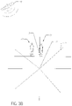
- FIG. 3A is a side view of a tracker being used in conjunction with a below ground magnetic field source and a GPS signal at a second location.
- the first location as represented in FIG. 2A is shown in dashed line.
- FIG. 3B is a back view of a tracker used in conjunction with a below ground magnetic field source and a GPS signal at the second location.
- the first location as represented in FIG. 2B is shown in dashed line.
- FIG. 3C is a top view of a tracker being used in conjunction with a below ground magnetic field source and a GPS signal at the second location.
- the ground surface is transparent so that the tracker location and beacon location can be displayed.
- the first location as represented in FIG. 2C is shown in dashed line.
- FIG. 4 is a perspective view of a triaxial antenna for use with a tracker.
- FIG. 5 is a side view of a tracker apparatus with a triaxial antenna, processor, and orientation sensor located within the case and represented with dashed lines.
- FIG. 6A is a display for use with the tracker, representative of the tracker at the first position.
- FIG. 6B is a display for use with the tracker, representative of the tracker at the second position prior to determining the position of the detected null relative to the beacon.
- FIG. 6C is a display for use with the tracker, representative of the tracker after determining the position of the two null points relative to the beacon.
- FIG. 1 shows a horizontal directional drilling machine 20 which is driving a drill string 14 in an underground environment.
- the drill string 14 supports a bit 16 at its distal end.
- the bit 16 is disposed just in front of a beacon 12 .
- the beacon 12 emits a dipole magnetic field 21 into the underground environment which is detectable at an above ground location.
- a tracker 10 is used to determine the location of the beacon 12 .
- An exemplar tracker 10 is disclosed and discussed in U.S. Pat. No. 7,647,987, issued to Cole, the contents of which are incorporated herein by reference.
- GPS global positioning system
- the GPS data is used in aiding the tracker 10 to locate the beacon 12 .
- the magnetic field emitted by the beacon 12 has a null point 22 .
- the magnetic field has a front null 22 a disposed in front of the bit 16 ( FIG. 1 ) and beacon 12 , and a rear null 22 b disposed between the beacon and the drilling machine 20 .
- the null point 22 is important, as it may be used to isolate field geometry and achieve precise depth and location readings.
- the tracker 10 comprises an orientation sensor 30 , a GPS receiver 32 , and an antenna 34 , each supported on the same frame 36 .
- the orientation sensor 30 comprises a compass to determine the angle of the tracker relative to magnetic north.
- the orientation sensor 30 may further comprise an accelerometer, gyro, and other instruments for determining a tilt of the tracker 10 frame 36 relative to vertical.
- the GPS receiver 32 is configured to receive signals from a global positioning system 40 .
- the global positioning system 40 is represented in FIGS. 2A-2B, 3A-3B by a satellite. It should be understood that the global positioning system 40 maintained by the United States government provides geolocation and time information to receivers having line-of-sight with the system 40 . Typically, line-of-sight with four or more satellites is optimal.
- the GPS receiver 32 preferably is accurate to 30 centimeters or less. In ideal conditions, accuracy of four centimeters or less is possible.
- a processor 38 in communication with the antenna 34 , GPS receiver 32 , and orientation sensor 30 may be provided on the frame 36 .
- the processor 38 may receive signals from each of these components, and make determinations regarding the shape of the magnetic field emitted by the beacon 12 based on the signals.
- the processor 38 may be located remotely from the frame 36 .
- the processor 38 may cause information to be displayed on a display 60 ( FIGS. 6A-6C ).
- the processor 38 may also include a memory for storing information related to the signals received.
- the antenna 34 is supported at a lower end of the frame 36 .
- the antenna 34 comprises three components 51 , 52 , 53 oriented about orthogonal axes.
- Each component 51 , 52 , 53 support one or more windings 56 set about the perimeter of the associated component.
- Each antenna component 51 , 52 , 53 preferably has the same center point and equivalent area, with dual, paired windings wound in the opposite direction, as set forth in U.S. Pat. No. 8,928,323, Issued to Cole, the contents of which are incorporated herein by reference.
- Windings 56 may be litz wire, solid magnet wire, or other antenna wire known in the art. Similar antenna 34 designs with single windings 56 may also be used.
- FIGS. 2A-3C a procedure for determining field characteristics is shown.
- FIGS. 2A-2C show a first measurement taken at the tracker 10 of the magnetic field 21 emitted by beacon 12 .
- FIGS. 3A-3C show a second measurement taken at the field null point 22 , with the previous measurement's location shown in dashed lines.
- FIGS. 2A and 3A are shown from the side of the beacon 12
- FIGS. 2B and 3B are shown from directly behind the beacon
- FIGS. 2C and 3C are shown from above, with the ground surface being transparent so that the tracker 10 location and beacon 12 can both be shown.
- the antenna 34 detects vector components of the magnetic field 21 .
- This information allows the processor 38 to determine potential above-ground locations of the first location 70 relative to the underground beacon 12 emitting the field 21 .
- the information also uses the vector angles detected at each component 51 , 52 , 53 of the antenna 34 to estimate a direction to the closest null point 22 . It should be understood that the relative detected vectors at one location cannot determine the absolute location of the beacon 12 or identification of the null point 22 , as the magnetic field 21 may have more than one location exhibiting a particular set of characteristics.
- the first measurement is taken, providing the onboard processor of the tracker 10 with information about signal strength in the x, y, and z plane based on detection by the tri-axial antenna 34 . Additionally, the absolute location of the antenna 34 as detected by the GPS receiver 32 is recorded. This location indicates the position of the tracker 10 to an acceptable rate of error. Simultaneously, the orientation sensor 30 sends a signal indicative of the heading and tilt, if any, of the tracker 10 frame 36 . Thus, corrections to the detected field due to frame 36 orientation may be considered.
- the tracker 10 is then moved to a second location 72 .
- the second location 72 is a null point 22 , but the discussion herein is similar if the second location 72 is not a null.
- the tracker 10 may be moved to a second location, and a second measurement taken.
- the second measurement provides the same information as the first measurement—namely signal strength in the x, y, and z planes and the absolute location of the antenna 34 as received by the GPS receiver 32 .
- the processor 38 may then compare the values of the second measurement to the first measurement.
- the processor 38 further knows the absolute locations of the first and second measurement, and the vector distance between the locations at which each measurement was taken. Critical to the method are the relative signal strengths of the two measurements and the movement of the tracker 10 toward or away from the drilling machine 20 when moving to the second location. This comparison allows the processor 38 to determine the shape of the field, the origin of the field at the beacon 12 , the location of the null points 22 relative to the tracker 10 , and the absolute positions of the beacon 12 and tracker 10 .
- an operating tracker may take iterative measurements of the magnetic field 21 on an ongoing basis. Such iterations will allow the processor 38 to make refinements to the measured locations of the null points 22 and track the beacon 12 when it is advanced by the drill string 14 .
- the processor 38 may use the two most recent measurements, or may use more than two measurements in determining characteristics of the magnetic field 21 .
- the location of a beacon 12 or a null point 22 could be determined relative to two above-ground locations only when certain variables were known.
- the field equations given in Cole '101 require that the antennas be within a “transmitter” plane—that is, the frame is maintained in a position where the two measurement points are perpendicular to the axis of a beacon 12 . (See Col. 9, ll. 46-49.) Because the GPS receiver 32 makes absolute position available to the processor 38 of the tracker 10 without requiring that the measurements are taken in a particular orientation, such limitations in previous tracking solutions can be overcome.
- the display 60 comprises a level indicator 62 , which is a display of the tilt as detected by the orientation sensor 30 .
- Indications of beacon 12 temperature, signal strength, battery level and frequency are given in area 64 .
- Beacon 12 roll position, pitch indicator, and suggested steering corrections are shown in area 65 .
- a target 66 is in the middle of the display 60 .
- the target 66 represents the approximate location of the closest null 22 .
- a dot 67 represents the location of the tracker 10 .
- the tracker 10 is moved to the null 22 location. As a result, the dot 67 is shown within the target 66 .
- the magnetic field has two null points 22 , one in front of the beacon 12 and one behind.
- the null points 22 have indistinguishable characteristics.
- the absolute position of the first location 70 ( FIGS. 2A-2C ), second location 72 ( FIGS. 3A-3C ), and drilling machine 20 are known.
- the tracker 10 When the tracker 10 is in the configuration of FIG. 6A , the tracker 10 needs to be moved forward and to the right so that the dot 67 enters the target 66 , as in FIG. 6B . At this point, any further movement will reveal which null point 22 was found. If the operator moves away from the drilling machine 20 and the signal increases, the null found is the rear null 22 b . Conversely, if the operator moves the tracker 10 away from the drilling machine 20 and the magnetic field 21 signal decreases, the null point 22 found is the front null 22 a . This is because the overall magnetic field 21 signal emanating from the beacon 12 is essentially a normal curve with the maximum signal being located directly above the beacon.
- each null 22 and the beacon 12 When the location and identification of each null 22 and the beacon 12 is complete, a representation of the tracker location, beacon location, and each null location may be shown on the display 60 , as shown in FIG. 6C .
- a second target 68 is placed at the position of the other null, and a beacon 12 indicator 69 is shown halfway between the targets 66 , 68 .
- the target 66 is the rear null 22 b and the second target 68 is the front null 22 a.
- the magnetic field 21 strength approximates a normal curve for all lines parallel to the orientation of the beacon 12 . Therefore, it should be understood that magnetic field measurements, absolute locations, and the location of drilling machine 20 may be used by the processor to identify the null as a front null 22 a or rear null 22 b . Thus, the second measurement may take place at any location within the magnetic field 21 to determine an estimated beacon 12 position relative to the detected null 22 and the drilling machine 20 , allowing the map of FIG. 6C to be generated.
- the dot 67 will move around the local map on the display 60 as the tracker 10 moves.
- the tracker 10 may be placed at the front null 22 a as represented by the second target 68 or over the beacon 12 as represented by the indicator 69 as needed for the particular task.
- the magnetic field 21 signal can be used to verify the initial location estimates determined by the processor 38 .
- the beacon 12 and GPS signals can also be used to continually correct and adjust the locations of the different points of interest, such as the null points 22 . As the drill string 14 advances the bit 16 and beacon 12 , its absolute position can be tracked as the magnetic field 21 source moves in the underground environment.
- the estimated beacon depth and a predicted depth of the beacon 12 along a projected path may be calculated. Depth may be estimated using known equations for the remaining component of the field—that is—the vertical component thereof as detected by the component 51 of the antenna 34 perpendicular to the vertical direction.
- the local map generated at the display 60 can be overlaid on actual map images, such as those available at Google maps, whether through a Bluetooth connection, or loaded from a memory card, etc.
Abstract
Description
Claims (18)
Priority Applications (2)
| Application Number | Priority Date | Filing Date | Title |
|---|---|---|---|
| US16/549,740 US11397266B2 (en) | 2018-08-29 | 2019-08-23 | GPS assisted walkover locating system and method |
| US17/857,623 US20220334266A1 (en) | 2018-08-29 | 2022-07-05 | Gps assisted walkover locating system and method |
Applications Claiming Priority (2)
| Application Number | Priority Date | Filing Date | Title |
|---|---|---|---|
| US201862724161P | 2018-08-29 | 2018-08-29 | |
| US16/549,740 US11397266B2 (en) | 2018-08-29 | 2019-08-23 | GPS assisted walkover locating system and method |
Related Child Applications (1)
| Application Number | Title | Priority Date | Filing Date |
|---|---|---|---|
| US17/857,623 Continuation US20220334266A1 (en) | 2018-08-29 | 2022-07-05 | Gps assisted walkover locating system and method |
Publications (2)
| Publication Number | Publication Date |
|---|---|
| US20200072983A1 US20200072983A1 (en) | 2020-03-05 |
| US11397266B2 true US11397266B2 (en) | 2022-07-26 |
Family
ID=69639854
Family Applications (2)
| Application Number | Title | Priority Date | Filing Date |
|---|---|---|---|
| US16/549,740 Active 2040-09-22 US11397266B2 (en) | 2018-08-29 | 2019-08-23 | GPS assisted walkover locating system and method |
| US17/857,623 Pending US20220334266A1 (en) | 2018-08-29 | 2022-07-05 | Gps assisted walkover locating system and method |
Family Applications After (1)
| Application Number | Title | Priority Date | Filing Date |
|---|---|---|---|
| US17/857,623 Pending US20220334266A1 (en) | 2018-08-29 | 2022-07-05 | Gps assisted walkover locating system and method |
Country Status (1)
| Country | Link |
|---|---|
| US (2) | US11397266B2 (en) |
Citations (68)
| Publication number | Priority date | Publication date | Assignee | Title |
|---|---|---|---|---|
| GB2006438A (en) | 1977-08-02 | 1979-05-02 | Electricity Council | Apparatus for Locating Electric Conductors |
| EP0045486A2 (en) | 1980-07-31 | 1982-02-10 | Metrotech Corporation | Apparatus for determining the distance to a concealed conductive object |
| US4390836A (en) | 1980-08-11 | 1983-06-28 | Marathon Oil Company | Method and apparatus for the detection of pipeline holidays |
| US4542344A (en) | 1983-09-02 | 1985-09-17 | Corrosion Logging Service International | Detecting buried pipeline depth and location with electromagnetic triangulation |
| US4742356A (en) | 1985-12-09 | 1988-05-03 | Mcdonnell Douglas Corporation | Method and apparatus for determining remote object orientation and position |
| US4812812A (en) | 1986-10-23 | 1989-03-14 | Gas Research Institute, Inc. | Apparatus and method for determining the position and orientation of a remote object |
| JPH0221288A (en) | 1988-07-09 | 1990-01-24 | Tokyo Gas Co Ltd | Plane distribution measuring apparatus for magnetic field |
| US5264795A (en) | 1990-06-18 | 1993-11-23 | The Charles Machine Works, Inc. | System transmitting and receiving digital and analog information for use in locating concealed conductors |
| US5397986A (en) | 1991-11-01 | 1995-03-14 | Federal Labs Systems Lp | Metal detector system having multiple, adjustable transmitter and receiver antennas |
| WO1995030913A1 (en) | 1994-05-06 | 1995-11-16 | Radiodetection Limited | Locator |
| US5529437A (en) | 1994-09-13 | 1996-06-25 | Filipowski; Mark S. | Guidance system and method for keeping a tunnel boring machine continuously on a plan line |
| DE19533105A1 (en) | 1995-04-11 | 1996-10-17 | Kyung Chang Ind Co | High sensitivity non-directional loop antenna arrangement e.g for high frequency |
| US5576973A (en) * | 1994-04-18 | 1996-11-19 | Radiodetection Limited | Apparatus and method for obtaining geographical positional data for an object located underground |
| US5640092A (en) | 1990-09-27 | 1997-06-17 | Motazed; Behnam | Electromagnetic pipe mapper for accurate location and depth determination |
| US5699048A (en) | 1996-10-03 | 1997-12-16 | Industrial Technology Inc. | Omnidirectional passive electrical marker for underground use |
| US6005532A (en) | 1997-04-16 | 1999-12-21 | Digital Control Incorporated | Orthogonal antenna arrangement and method |
| WO2000010456A1 (en) | 1998-08-02 | 2000-03-02 | Super Dimension Ltd. | Intrabody navigation system for medical applications |
| US6250402B1 (en) | 1997-04-16 | 2001-06-26 | Digital Control Incorporated | Establishing positions of locating field detectors and path mappings in underground boring tool applications |
| US6268731B1 (en) | 1997-03-07 | 2001-07-31 | Radiodetection Ltd | Locator of electrically conductive objects |
| US20020020559A1 (en) | 2000-05-16 | 2002-02-21 | Barbera James S. | Auger drill directional control system |
| US20020116129A1 (en) | 1999-01-13 | 2002-08-22 | Vermeer Manufacturing Company | Automated bore planning method and apparatus for horizontal directional drilling |
| US6563474B2 (en) | 2000-12-21 | 2003-05-13 | Lear Corporation | Remote access device having multiple inductive coil antenna |
| JP2003249816A (en) | 2002-02-25 | 2003-09-05 | Shin Denshi Co Ltd | Antenna coil |
| US20040070399A1 (en) | 2002-10-09 | 2004-04-15 | Olsson Mark S. | Omnidirectional sonde and line locator |
| US6737867B2 (en) | 2001-08-22 | 2004-05-18 | Merlin Technology, Inc. | Locating arrangement and method using boring tool and cable locating signals |
| US20040190374A1 (en) | 1999-09-24 | 2004-09-30 | Vermeer Manufacturing Company | Earth penetrating apparatus and method employing radar imaging and rate sensing |
| US6865455B1 (en) | 2003-02-19 | 2005-03-08 | The United States Of America As Represented By The Secretary Of The Navy | Magnetic anomaly guidance system and method |
| US6868314B1 (en) | 2001-06-27 | 2005-03-15 | Bentley D. Frink | Unmanned aerial vehicle apparatus, system and method for retrieving data |
| US6882154B2 (en) | 1996-05-03 | 2005-04-19 | Merlin Technology, Inc. | Tracking the positional relationship between a boring tool and one or more buried lines using a composite magnetic signal |
| EP1526606A1 (en) | 2003-10-20 | 2005-04-27 | Toko Kabushiki Kaisha | Triaxial antenna coil |
| US6924767B2 (en) | 2002-06-04 | 2005-08-02 | Denso Corporation | Reception antenna, core, and portable device |
| US20060036376A1 (en) * | 2004-07-29 | 2006-02-16 | Thorkell Gudmundsson | Precise location of buried metallic pipes and cables in the presence of signal distortion |
| US7000710B1 (en) | 2002-04-01 | 2006-02-21 | The Charles Machine Works, Inc. | Automatic path generation and correction system |
| US20060055584A1 (en) * | 2003-11-25 | 2006-03-16 | Waite James W | Sensor fusion for model-based detection in pipe and cable locator systems |
| US7013990B1 (en) | 2002-12-11 | 2006-03-21 | The Charles Machine Works, Inc. | Apparatus and method for simultaneously locating a fixed object and tracking a beacon |
| US7111693B1 (en) | 2002-11-26 | 2006-09-26 | The Charles Machine Works, Inc. | System and method for locating and tracking a boring tool |
| WO2006124520A2 (en) | 2005-05-13 | 2006-11-23 | The Charles Machine Works, Inc. | Dipole locator using multiple measurement points |
| US20070044536A1 (en) | 2005-08-23 | 2007-03-01 | The Charles Machine Works, Inc. | System For Tracking And Maintaining An On-Grade Horizontal Borehole |
| US7231320B2 (en) | 2004-11-22 | 2007-06-12 | Papadimitriou Wanda G | Extraction of imperfection features through spectral analysis |
| US7350594B2 (en) | 2003-06-17 | 2008-04-01 | The Charles Machine Works, Inc. | System and method for tracking and communicating with a boring tool |
| US20090153141A1 (en) | 1991-03-01 | 2009-06-18 | Mercer John E | Flux Orientation Locating in a Drilling System |
| US20100001731A1 (en) | 2008-02-29 | 2010-01-07 | Radiodetection Limited | Transmitter of a System for Detecting a Buried Conductor |
| US20100002938A1 (en) | 2005-02-16 | 2010-01-07 | Mulcahey Butch Aka Donald M | Method of displaying digital image for digital locating system and device for underground object detection |
| US7647987B2 (en) | 2004-02-26 | 2010-01-19 | The Charles Machine Works, Inc. | Multiple antenna system for horizontal directional drilling |
| US7656159B2 (en) | 2007-09-10 | 2010-02-02 | The United States Of America As Represented By The Secretary Of The Army | Locating stationary magnetic objects |
| US7952357B2 (en) | 2007-09-28 | 2011-05-31 | The Charles Machines Works, Inc. | Receiver system for determining the location of a magnetic field source |
| US8018382B2 (en) | 2005-12-16 | 2011-09-13 | Raytheon Utd Inc. | Positioning system and method |
| US8072220B2 (en) | 2005-12-16 | 2011-12-06 | Raytheon Utd Inc. | Positioning, detection and communication system and method |
| US8188745B2 (en) * | 2008-12-05 | 2012-05-29 | Metrotech Corporation Inc. | Precise location and orientation of a concealed dipole transmitter |
| US20120146648A1 (en) | 2010-12-14 | 2012-06-14 | Conocophillips Company | Autonomous electrical methods node |
| US20130175092A1 (en) | 2012-01-05 | 2013-07-11 | Merlin Technology, Inc. | Directional drilling target steering apparatus and method |
| US20140111211A1 (en) | 2007-09-28 | 2014-04-24 | The Charles Machines Works, Inc. | Method For Guiding A Downhole Tool Assembly Using An Above-Ground Receiver System |
| US20140163775A1 (en) | 2011-04-14 | 2014-06-12 | Hexagon Technology Center Gmbh | Geodetic marking system for marking target points |
| US20140222248A1 (en) | 2012-12-19 | 2014-08-07 | Elwha LLC, a limited liability corporation of the State of Delaware | Unoccupied flying vehicle (ufv) coordination |
| US20140303814A1 (en) | 2013-03-24 | 2014-10-09 | Bee Robotics Corporation | Aerial farm robot system for crop dusting, planting, fertilizing and other field jobs |
| US8928323B2 (en) | 2005-05-13 | 2015-01-06 | The Charles Machines Works, Inc. | Dipole locator using multiple measurement points |
| US20150090496A1 (en) | 2011-06-21 | 2015-04-02 | Vermeer Manufacturing Company | Horizontal directional drilling system including sonde position detection using global positioning systems |
| US20150149000A1 (en) | 2013-01-04 | 2015-05-28 | Parrot | Unkown |
| US20160018551A1 (en) | 2014-07-17 | 2016-01-21 | The Charles Machine Works, Inc. | Device and Method for Tracking a Downhole Tool |
| US9329297B2 (en) * | 2005-05-13 | 2016-05-03 | The Charles Machine Works, Inc. | Dipole locator using multiple measurement points |
| US20160356146A1 (en) | 2014-06-06 | 2016-12-08 | The Charles Machine Works, Inc. | External Hollow Antenna |
| US20170226805A1 (en) | 2016-02-05 | 2017-08-10 | The Charles Machine Works, Inc. | Method And System For Guiding A Downhole Tool Underground |
| US20170299755A1 (en) | 2014-07-17 | 2017-10-19 | The Charles Machine Works, Inc. | Airborne Locator Of An Underground Object |
| US20180299575A1 (en) * | 2017-04-14 | 2018-10-18 | The Charles Machine Works, Inc. | System For Locating A Utility With A Downhole Beacon |
| US20190004203A1 (en) * | 2016-12-16 | 2019-01-03 | Seescan Inc. | Systems and methods for electronically marking, locating and virtually displaying buried utilities |
| US10822941B2 (en) * | 2015-07-21 | 2020-11-03 | The Charles Machine Works, Inc. | Underground guidance using above-ground mesh network |
| US20210131615A1 (en) * | 2017-04-25 | 2021-05-06 | The Charles Machine Works, Inc. | Pipeline Following Sensor Arrangement |
| US11149539B2 (en) * | 2019-07-23 | 2021-10-19 | Merlin Technology, Inc. | Drill planning tool for topography characterization, system and associated methods |
Family Cites Families (8)
| Publication number | Priority date | Publication date | Assignee | Title |
|---|---|---|---|---|
| US9081109B1 (en) * | 2010-06-15 | 2015-07-14 | See Scan, Inc. | Ground-tracking devices for use with a mapping locator |
| US10877176B2 (en) * | 2014-07-17 | 2020-12-29 | The Charles Machine Works, Inc. | Airborne locator of an underground object |
| US20170022800A1 (en) * | 2015-07-21 | 2017-01-26 | The Charles Machine Works, Inc. | Tracker With Electronic Compass And Method Of Use |
| US10162074B2 (en) * | 2016-03-11 | 2018-12-25 | SeeScan, Inc. | Utility locators with retractable support structures and applications thereof |
| US11639661B2 (en) * | 2019-08-12 | 2023-05-02 | The Charles Machine Works, Inc. | Augmented reality system for use in horizontal directional drilling operations |
| CN111173451A (en) * | 2020-01-19 | 2020-05-19 | 河北韶通翱达科技有限公司 | Non-excavation underground guiding system |
| US20230056853A1 (en) * | 2021-08-09 | 2023-02-23 | The Charles Machine Works, Inc. | Null point depth calibration |
| US20230314593A1 (en) * | 2022-03-30 | 2023-10-05 | The Charles Machine Works, Inc. | Autonomous hdd tracking system with rover |
-
2019
- 2019-08-23 US US16/549,740 patent/US11397266B2/en active Active
-
2022
- 2022-07-05 US US17/857,623 patent/US20220334266A1/en active Pending
Patent Citations (88)
| Publication number | Priority date | Publication date | Assignee | Title |
|---|---|---|---|---|
| GB2006438A (en) | 1977-08-02 | 1979-05-02 | Electricity Council | Apparatus for Locating Electric Conductors |
| EP0045486A2 (en) | 1980-07-31 | 1982-02-10 | Metrotech Corporation | Apparatus for determining the distance to a concealed conductive object |
| US4390836A (en) | 1980-08-11 | 1983-06-28 | Marathon Oil Company | Method and apparatus for the detection of pipeline holidays |
| US4542344A (en) | 1983-09-02 | 1985-09-17 | Corrosion Logging Service International | Detecting buried pipeline depth and location with electromagnetic triangulation |
| US4742356A (en) | 1985-12-09 | 1988-05-03 | Mcdonnell Douglas Corporation | Method and apparatus for determining remote object orientation and position |
| US4812812A (en) | 1986-10-23 | 1989-03-14 | Gas Research Institute, Inc. | Apparatus and method for determining the position and orientation of a remote object |
| JPH0221288A (en) | 1988-07-09 | 1990-01-24 | Tokyo Gas Co Ltd | Plane distribution measuring apparatus for magnetic field |
| US5264795A (en) | 1990-06-18 | 1993-11-23 | The Charles Machine Works, Inc. | System transmitting and receiving digital and analog information for use in locating concealed conductors |
| US5640092A (en) | 1990-09-27 | 1997-06-17 | Motazed; Behnam | Electromagnetic pipe mapper for accurate location and depth determination |
| US20090153141A1 (en) | 1991-03-01 | 2009-06-18 | Mercer John E | Flux Orientation Locating in a Drilling System |
| US5397986A (en) | 1991-11-01 | 1995-03-14 | Federal Labs Systems Lp | Metal detector system having multiple, adjustable transmitter and receiver antennas |
| US5576973A (en) * | 1994-04-18 | 1996-11-19 | Radiodetection Limited | Apparatus and method for obtaining geographical positional data for an object located underground |
| WO1995030913A1 (en) | 1994-05-06 | 1995-11-16 | Radiodetection Limited | Locator |
| US5529437A (en) | 1994-09-13 | 1996-06-25 | Filipowski; Mark S. | Guidance system and method for keeping a tunnel boring machine continuously on a plan line |
| DE19533105A1 (en) | 1995-04-11 | 1996-10-17 | Kyung Chang Ind Co | High sensitivity non-directional loop antenna arrangement e.g for high frequency |
| US6882154B2 (en) | 1996-05-03 | 2005-04-19 | Merlin Technology, Inc. | Tracking the positional relationship between a boring tool and one or more buried lines using a composite magnetic signal |
| US5699048A (en) | 1996-10-03 | 1997-12-16 | Industrial Technology Inc. | Omnidirectional passive electrical marker for underground use |
| US6268731B1 (en) | 1997-03-07 | 2001-07-31 | Radiodetection Ltd | Locator of electrically conductive objects |
| US6250402B1 (en) | 1997-04-16 | 2001-06-26 | Digital Control Incorporated | Establishing positions of locating field detectors and path mappings in underground boring tool applications |
| US8393414B2 (en) | 1997-04-16 | 2013-03-12 | Merlin Technology Inc. | Establishing positions of locating field detectors and path mapping in underground boring tool applications |
| US6005532A (en) | 1997-04-16 | 1999-12-21 | Digital Control Incorporated | Orthogonal antenna arrangement and method |
| US6364035B2 (en) | 1997-04-16 | 2002-04-02 | Digital Control Incorporated | Establishing positions of locating field detectors and path mapping in underground boring tool applications |
| US20130153299A1 (en) | 1997-04-16 | 2013-06-20 | Merlin Technology Inc. | Establishing positions of locating field detectors and path mapping in underground boring tool applications |
| US6536538B2 (en) | 1997-04-16 | 2003-03-25 | Digital Control Incorporated | Establishing positions of locating field detectors and path mapping in underground boring tool applications |
| US7347280B2 (en) | 1997-04-16 | 2008-03-25 | Merlin Technology, Inc. | Establishing positions of locating field detectors and path mapping in underground boring tool applications |
| US8025109B2 (en) | 1997-04-16 | 2011-09-27 | Merlin Technology, Inc. | Method for establishing the positions of a transmitter and detector in a region |
| US6668944B2 (en) | 1997-04-16 | 2003-12-30 | Merlin Technology, Inc. | Path mapping in underground boring tool applications |
| US7021403B2 (en) | 1997-04-16 | 2006-04-04 | Merlin Technology, Inc. | Method of establishing positions of locating field detectors and path mapping in underground boring tool applications |
| US6035951A (en) | 1997-04-16 | 2000-03-14 | Digital Control Incorporated | System for tracking and/or guiding an underground boring tool |
| US7562722B2 (en) | 1997-04-16 | 2009-07-21 | Merlin Technology, Inc. | Method and apparatus for establishing the position of a sonde in a region using a single detector |
| WO2000010456A1 (en) | 1998-08-02 | 2000-03-02 | Super Dimension Ltd. | Intrabody navigation system for medical applications |
| US6749029B2 (en) | 1999-01-13 | 2004-06-15 | Vermeer Manufacturing Company | Automated bore planning method and apparatus for horizontal directional drilling |
| US20020116129A1 (en) | 1999-01-13 | 2002-08-22 | Vermeer Manufacturing Company | Automated bore planning method and apparatus for horizontal directional drilling |
| US20040190374A1 (en) | 1999-09-24 | 2004-09-30 | Vermeer Manufacturing Company | Earth penetrating apparatus and method employing radar imaging and rate sensing |
| US20020020559A1 (en) | 2000-05-16 | 2002-02-21 | Barbera James S. | Auger drill directional control system |
| US6563474B2 (en) | 2000-12-21 | 2003-05-13 | Lear Corporation | Remote access device having multiple inductive coil antenna |
| US6868314B1 (en) | 2001-06-27 | 2005-03-15 | Bentley D. Frink | Unmanned aerial vehicle apparatus, system and method for retrieving data |
| US6737867B2 (en) | 2001-08-22 | 2004-05-18 | Merlin Technology, Inc. | Locating arrangement and method using boring tool and cable locating signals |
| JP2003249816A (en) | 2002-02-25 | 2003-09-05 | Shin Denshi Co Ltd | Antenna coil |
| US7000710B1 (en) | 2002-04-01 | 2006-02-21 | The Charles Machine Works, Inc. | Automatic path generation and correction system |
| US6924767B2 (en) | 2002-06-04 | 2005-08-02 | Denso Corporation | Reception antenna, core, and portable device |
| US20040070399A1 (en) | 2002-10-09 | 2004-04-15 | Olsson Mark S. | Omnidirectional sonde and line locator |
| US7009399B2 (en) | 2002-10-09 | 2006-03-07 | Deepsea Power & Light | Omnidirectional sonde and line locator |
| US7111693B1 (en) | 2002-11-26 | 2006-09-26 | The Charles Machine Works, Inc. | System and method for locating and tracking a boring tool |
| US7013990B1 (en) | 2002-12-11 | 2006-03-21 | The Charles Machine Works, Inc. | Apparatus and method for simultaneously locating a fixed object and tracking a beacon |
| US6865455B1 (en) | 2003-02-19 | 2005-03-08 | The United States Of America As Represented By The Secretary Of The Navy | Magnetic anomaly guidance system and method |
| US7350594B2 (en) | 2003-06-17 | 2008-04-01 | The Charles Machine Works, Inc. | System and method for tracking and communicating with a boring tool |
| US7042411B2 (en) | 2003-10-20 | 2006-05-09 | Toko Kabushiki Kaisha | Triaxial antenna coil |
| EP1526606A1 (en) | 2003-10-20 | 2005-04-27 | Toko Kabushiki Kaisha | Triaxial antenna coil |
| US20060055584A1 (en) * | 2003-11-25 | 2006-03-16 | Waite James W | Sensor fusion for model-based detection in pipe and cable locator systems |
| US7647987B2 (en) | 2004-02-26 | 2010-01-19 | The Charles Machine Works, Inc. | Multiple antenna system for horizontal directional drilling |
| US20060036376A1 (en) * | 2004-07-29 | 2006-02-16 | Thorkell Gudmundsson | Precise location of buried metallic pipes and cables in the presence of signal distortion |
| US7356421B2 (en) | 2004-07-29 | 2008-04-08 | Metrotech Corporation, Inc. | Precise location of buried metallic pipes and cables in the presence of signal distortion |
| US7231320B2 (en) | 2004-11-22 | 2007-06-12 | Papadimitriou Wanda G | Extraction of imperfection features through spectral analysis |
| US20100002938A1 (en) | 2005-02-16 | 2010-01-07 | Mulcahey Butch Aka Donald M | Method of displaying digital image for digital locating system and device for underground object detection |
| WO2006124520A2 (en) | 2005-05-13 | 2006-11-23 | The Charles Machine Works, Inc. | Dipole locator using multiple measurement points |
| US8928323B2 (en) | 2005-05-13 | 2015-01-06 | The Charles Machines Works, Inc. | Dipole locator using multiple measurement points |
| US7786731B2 (en) | 2005-05-13 | 2010-08-31 | The Charles Machine Works, Inc. | Dipole locator using multiple measurement points |
| US8497684B2 (en) | 2005-05-13 | 2013-07-30 | The Charles Machine Works, Inc. | Dipole locator using multiple measurement points |
| US9329297B2 (en) * | 2005-05-13 | 2016-05-03 | The Charles Machine Works, Inc. | Dipole locator using multiple measurement points |
| US20070044536A1 (en) | 2005-08-23 | 2007-03-01 | The Charles Machine Works, Inc. | System For Tracking And Maintaining An On-Grade Horizontal Borehole |
| US8018382B2 (en) | 2005-12-16 | 2011-09-13 | Raytheon Utd Inc. | Positioning system and method |
| US8072220B2 (en) | 2005-12-16 | 2011-12-06 | Raytheon Utd Inc. | Positioning, detection and communication system and method |
| US7656159B2 (en) | 2007-09-10 | 2010-02-02 | The United States Of America As Represented By The Secretary Of The Army | Locating stationary magnetic objects |
| US8482286B2 (en) | 2007-09-28 | 2013-07-09 | The Charles Machine Works, Inc. | Method for guiding a downhole tool assembly using an above-ground receiver system |
| US20140111211A1 (en) | 2007-09-28 | 2014-04-24 | The Charles Machines Works, Inc. | Method For Guiding A Downhole Tool Assembly Using An Above-Ground Receiver System |
| US20110227575A1 (en) | 2007-09-28 | 2011-09-22 | The Charles Machine Works, Inc. | Receiver System For Determining The Location Of A Magnetic Field Source |
| US7952357B2 (en) | 2007-09-28 | 2011-05-31 | The Charles Machines Works, Inc. | Receiver system for determining the location of a magnetic field source |
| US9547101B2 (en) * | 2007-09-28 | 2017-01-17 | The Charles Machine Works, Inc. | System for tracking a downhole tool assembly using dual above-ground receiver assemblies |
| US20100001731A1 (en) | 2008-02-29 | 2010-01-07 | Radiodetection Limited | Transmitter of a System for Detecting a Buried Conductor |
| US8188745B2 (en) * | 2008-12-05 | 2012-05-29 | Metrotech Corporation Inc. | Precise location and orientation of a concealed dipole transmitter |
| US20120146648A1 (en) | 2010-12-14 | 2012-06-14 | Conocophillips Company | Autonomous electrical methods node |
| US20140163775A1 (en) | 2011-04-14 | 2014-06-12 | Hexagon Technology Center Gmbh | Geodetic marking system for marking target points |
| US20150090496A1 (en) | 2011-06-21 | 2015-04-02 | Vermeer Manufacturing Company | Horizontal directional drilling system including sonde position detection using global positioning systems |
| US20130175092A1 (en) | 2012-01-05 | 2013-07-11 | Merlin Technology, Inc. | Directional drilling target steering apparatus and method |
| US20140222248A1 (en) | 2012-12-19 | 2014-08-07 | Elwha LLC, a limited liability corporation of the State of Delaware | Unoccupied flying vehicle (ufv) coordination |
| US20150149000A1 (en) | 2013-01-04 | 2015-05-28 | Parrot | Unkown |
| US20140303814A1 (en) | 2013-03-24 | 2014-10-09 | Bee Robotics Corporation | Aerial farm robot system for crop dusting, planting, fertilizing and other field jobs |
| US20160356146A1 (en) | 2014-06-06 | 2016-12-08 | The Charles Machine Works, Inc. | External Hollow Antenna |
| US20160018551A1 (en) | 2014-07-17 | 2016-01-21 | The Charles Machine Works, Inc. | Device and Method for Tracking a Downhole Tool |
| US20170299755A1 (en) | 2014-07-17 | 2017-10-19 | The Charles Machine Works, Inc. | Airborne Locator Of An Underground Object |
| US10459105B2 (en) * | 2014-07-17 | 2019-10-29 | The Charles Machine Works, Inc. | Airborne locator of an underground object |
| US10822941B2 (en) * | 2015-07-21 | 2020-11-03 | The Charles Machine Works, Inc. | Underground guidance using above-ground mesh network |
| US20170226805A1 (en) | 2016-02-05 | 2017-08-10 | The Charles Machine Works, Inc. | Method And System For Guiding A Downhole Tool Underground |
| US20190004203A1 (en) * | 2016-12-16 | 2019-01-03 | Seescan Inc. | Systems and methods for electronically marking, locating and virtually displaying buried utilities |
| US20180299575A1 (en) * | 2017-04-14 | 2018-10-18 | The Charles Machine Works, Inc. | System For Locating A Utility With A Downhole Beacon |
| US20210131615A1 (en) * | 2017-04-25 | 2021-05-06 | The Charles Machine Works, Inc. | Pipeline Following Sensor Arrangement |
| US11149539B2 (en) * | 2019-07-23 | 2021-10-19 | Merlin Technology, Inc. | Drill planning tool for topography characterization, system and associated methods |
Non-Patent Citations (1)
| Title |
|---|
| Subsite Electronics, "TK RECON Series Guidance System", Operator's Manual, Jun. 2016, 63 pages, Perry, Oklahoma. |
Also Published As
| Publication number | Publication date |
|---|---|
| US20220334266A1 (en) | 2022-10-20 |
| US20200072983A1 (en) | 2020-03-05 |
Similar Documents
| Publication | Publication Date | Title |
|---|---|---|
| US9158024B2 (en) | System for determining a precise location and orientation of a concealed dipole transmitter | |
| US9151822B2 (en) | Precise positioning using a distributed sensor network | |
| US7619561B2 (en) | Managed traverse system and method to acquire accurate survey data in absence of precise GPS data | |
| US7397422B2 (en) | Method and system for attitude determination of a platform using global navigation satellite system and a steered antenna | |
| KR20130093526A (en) | Determining spatial orientation information of a body from multiple electromagnetic signals | |
| US20040163850A1 (en) | Boring tool tracking/guiding system and method with unconstrained target location geometry | |
| US10048073B2 (en) | Beacon-based geolocation using a low frequency electromagnetic field | |
| US8769838B2 (en) | Surveyor 's rod and magnetic locator | |
| US10976441B2 (en) | Method of using GNSS system having magnetic locator | |
| JP2001505666A (en) | Exploration method including exploration method and wireless navigation device | |
| EP1726915A1 (en) | Active surveying pole | |
| KR100715178B1 (en) | Method For Determining Position Of An Object | |
| KR101763911B1 (en) | Heading estimation apparatus of auv in severe magnetic disturbance environment and the method thereof | |
| CA2893361C (en) | Determination of initial tool orientation | |
| EP2040029A1 (en) | A multi mode active surveying pole | |
| US11397266B2 (en) | GPS assisted walkover locating system and method | |
| US20230176233A1 (en) | Gnss positioning methods and devices using ppp-rtk, rtk, ssr, or like correction data | |
| WO2013102154A1 (en) | Coarse attitude determination from gnss antenna gain profiling | |
| JP7308294B2 (en) | Precision line positioner, how to accurately determine the position of underground lines | |
| KR100915121B1 (en) | Unmanned vehicle using dgnss and guiding method | |
| US9310460B2 (en) | Method and detector for searching a transmitter | |
| KR102036080B1 (en) | Portable positioning device and method for operating portable positioning device | |
| US20130214975A1 (en) | Target location positioning method and device | |
| RU2792068C1 (en) | Underground communication line locator | |
| JP2004012258A (en) | Remote positioning system, remote positioning method, and computer software |
Legal Events
| Date | Code | Title | Description |
|---|---|---|---|
| FEPP | Fee payment procedure |
Free format text: ENTITY STATUS SET TO UNDISCOUNTED (ORIGINAL EVENT CODE: BIG.); ENTITY STATUS OF PATENT OWNER: LARGE ENTITY |
|
| AS | Assignment |
Owner name: SUBSITE, LLC, OKLAHOMA Free format text: ASSIGNMENT OF ASSIGNORS INTEREST;ASSIGNORS:COLE, SCOTT B.;SCHROCK, BRIAN J.;JONES, KLAYTON DAY;SIGNING DATES FROM 20190903 TO 20190913;REEL/FRAME:050586/0966 |
|
| STPP | Information on status: patent application and granting procedure in general |
Free format text: NON FINAL ACTION MAILED |
|
| STPP | Information on status: patent application and granting procedure in general |
Free format text: RESPONSE TO NON-FINAL OFFICE ACTION ENTERED AND FORWARDED TO EXAMINER |
|
| STPP | Information on status: patent application and granting procedure in general |
Free format text: NOTICE OF ALLOWANCE MAILED -- APPLICATION RECEIVED IN OFFICE OF PUBLICATIONS |
|
| AS | Assignment |
Owner name: THE CHARLES MACHINE WORKS, INC., OKLAHOMA Free format text: ASSIGNMENT OF ASSIGNORS INTEREST;ASSIGNOR:SUBSITE, LLC;REEL/FRAME:060325/0330 Effective date: 20191217 |
|
| STCF | Information on status: patent grant |
Free format text: PATENTED CASE |
|
| CC | Certificate of correction |