EP2802047B1 - Kühlkörper für Kontaktgeber in Stromverteilerbaugruppe - Google Patents
Kühlkörper für Kontaktgeber in Stromverteilerbaugruppe Download PDFInfo
- Publication number
- EP2802047B1 EP2802047B1 EP14167309.5A EP14167309A EP2802047B1 EP 2802047 B1 EP2802047 B1 EP 2802047B1 EP 14167309 A EP14167309 A EP 14167309A EP 2802047 B1 EP2802047 B1 EP 2802047B1
- Authority
- EP
- European Patent Office
- Prior art keywords
- fins
- contactor assembly
- assembly according
- electrical contactor
- electrical
- Prior art date
- Legal status (The legal status is an assumption and is not a legal conclusion. Google has not performed a legal analysis and makes no representation as to the accuracy of the status listed.)
- Active
Links
Images




Classifications
-
- H—ELECTRICITY
- H05—ELECTRIC TECHNIQUES NOT OTHERWISE PROVIDED FOR
- H05K—PRINTED CIRCUITS; CASINGS OR CONSTRUCTIONAL DETAILS OF ELECTRIC APPARATUS; MANUFACTURE OF ASSEMBLAGES OF ELECTRICAL COMPONENTS
- H05K7/00—Constructional details common to different types of electric apparatus
- H05K7/20—Modifications to facilitate cooling, ventilating, or heating
- H05K7/20009—Modifications to facilitate cooling, ventilating, or heating using a gaseous coolant in electronic enclosures
- H05K7/20136—Forced ventilation, e.g. by fans
- H05K7/20154—Heat dissipaters coupled to components
-
- H—ELECTRICITY
- H02—GENERATION; CONVERSION OR DISTRIBUTION OF ELECTRIC POWER
- H02B—BOARDS, SUBSTATIONS OR SWITCHING ARRANGEMENTS FOR THE SUPPLY OR DISTRIBUTION OF ELECTRIC POWER
- H02B1/00—Frameworks, boards, panels, desks, casings; Details of substations or switching arrangements
- H02B1/56—Cooling; Ventilation
-
- H—ELECTRICITY
- H02—GENERATION; CONVERSION OR DISTRIBUTION OF ELECTRIC POWER
- H02B—BOARDS, SUBSTATIONS OR SWITCHING ARRANGEMENTS FOR THE SUPPLY OR DISTRIBUTION OF ELECTRIC POWER
- H02B1/00—Frameworks, boards, panels, desks, casings; Details of substations or switching arrangements
- H02B1/015—Boards, panels, desks; Parts thereof or accessories therefor
- H02B1/04—Mounting thereon of switches or of other devices in general, the switch or device having, or being without, casing
- H02B1/056—Mounting on plugboards
Definitions
- This invention generally relates to the field of electrical contactors and, more particularly, to a heat sink for dissipating heat generated by an electrical contactor connected to a mounting panel.
- Contactor assemblies are used in electrical applications, such as aircraft power distribution systems, where power and current flow control of a multi-phase power distribution system is required.
- a contactor assembly typically has a panel on which several electrical contactors are mounted.
- Known mounting assemblies used to mount electrical contactors to the panels are constructed of thermally and electrically resistive materials, such as plastics or FR-4 for example.
- Each of the contactors is connected to an electrical bus bar, and allows current to flow through the contactor and the corresponding bus bar whenever the contactor is in a closed position.
- the electrical power and current flow through the contactors is controlled by mechanically actuating a contact plate within the contactor such that, when current flow is desired to pass through the contactor, the contact plate is pushed into electrical contact with two leads and forms an electrical path coupling the leads, thereby allowing current to flow through it. Due to the amount of current traveling from the leads to the connector and the contact resistance at the contact points, waste heat is generated at the contact points and should be removed in order to prevent heat buildup. Additional factors such as imperfections in the contact surfaces or other imperfections can add to the amount of waste heat generated.
- US 7,837,496 relates to an electrical panel connector having a base plate and multiple posts protruding through the base plate, as defined by the preamble of claim 1.
- an electrical contactor assembly (claim 1) including an electrical contactor, an electrical bus bar, and a panel formed from an electrically insulating material. At least one post protrudes through the panel and is in contact with the electrical bus bar. At least one post is constructed from an electrically and thermally conductive material. A first end of the at least one post is configured to electrically and thermally connect to the electrical contactor.
- a heat sink is removably coupled to a second end of the at least one post.
- the heat sink includes a body having a plurality of fins extending radially outward. A first portion of the plurality of fins extends around a circumference of the body. A second portion of the plurality of fins extends around only a portion of the circumference of the body.
- the aircraft 10 includes a power generation system 20, which utilizes rotation within the jet engines 22 to generate either single phase or three phase electrical power.
- the power is sent to a panel box 24 that contains multiple electrical buses and contactor assemblies 100 for controlling how the power is distributed throughout the aircraft 10. Through the use of the electrical contactor assemblies 100, power may be controlled for each onboard electrical system 26 independently.
- FIG. 2 An example of the interior of a panel box 24 is illustrated in FIG. 2 .
- the interior of the panel box 24 has multiple electrical bus bars 50, which are interrupted by electrical contactor connections 52. When the contactor connections 52 are closed, electrical current and heat are allowed to flow between the connected bus bars 50 and a contactor 54. In known systems, all of the excess heat generated in the contactors 54 is transmitted to the bus bars 50 for dissipation by radiation into the ambient atmosphere.
- the contactor assembly 100 has at least one post 104 for connecting a contactor 54 to a first side of a bus bar 50 and at least one post 106 for connecting the contactor 54 to a second side of a bus bar 50.
- the electrical contactor 54 connects to the posts 104, 106 of the contactor assembly 100 via a set of electrical leads 108 using known thermal and electrical connection techniques.
- the posts 104, 106 are electrically and thermally coupled to the bus bars 50.
- the contactor assembly 100 additionally includes a panel 110 including multiple holes 112 through which the posts 104, 106 extend.
- the posts 104, 106 are in direct contact with the panel 110.
- a structural support 114 is positioned at the interface between the posts 104, 106 and the panel 110 to mechanically fasten each post 104, 106 to the panel 110.
- fasteners such as screws for example, connect the structural support 114 to the panel 110.
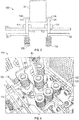
- a heat sink 130 is mounted to the end of at least one of the posts 104, 106 extending through both the panel 110 and the bus bar 50.
- the overall size, shape, and fin configuration of the heat sink 130 disclosed herein may be generally determined by the amount of heat to be dissipated.
- the illustrated heat sinks 130 include a substantially cylindrical body 132 having a plurality of fins 138 extending radially outwardly therefrom.
- the fins 138 are arranged generally parallel and are generally evenly spaced over the length of the body 132 between a first end 134 and a second, opposite end 136.
- the fins 138 have a generally rectangular cross-section that remains constant around the circumference of the cylindrical body 132.
- Fins 138 having a cross-section of another shape, such as triangular or trapezoidal for example, or a cross-section that varies about the periphery of the cylindrical body 132 are also within the scope of the invention.
- the plurality of fins 138 extends generally circumferentially (either completely or partially) about the outer diameter of the cylindrical body 132.
- a first portion 140 of the plurality of fins 138 extends about the entire circumference of the cylindrical body 132, and a second portion 142 of the plurality of fins 138 extends only partially about the circumference of the cylindrical body 132.
- the second portion 142 of fins 38 may be positioned about the cylindrical body 132 to avoid interference with an adjacent heat sink 130 or other component of the contactor assembly 100.
- the number of fins 138 within each of the first portion 140 and the second portion 142 may, but need not be, the same.
- both the first portion 140 and the second portion 142 of the exemplary heat sink 130 illustrated in FIG. 5 include four fins 138.
- the first portion 140 of fins 138 of the exemplary heat sink 130 illustrated in FIG. 6 includes five fins 138 and the second portion 142 includes only one fin 138.
- a first end of the cylindrical body is configured to couple to the free end of one of the posts 104, 106.
- the cylindrical body 132 has a substantially hollow interior 144 except for an interior portion 146 adjacent the first end 134 (see FIG. 7 ).
- the interior portion 146 includes a through hole 148 configured to receive a fastener, such as a screw for example, arranged within the substantially hollow interior 144 of the cylindrical body 132.
- a plurality of threads formed into the cylindrical body 132 such as the through hole 148 of the interior portion 146 for example, are configured to mate with a plurality of complementary threads on posts 104, 106.
- a heat sink 130 may be mounted to some or each post 104, 106 extending from the contactor 54.
- each of the plurality of heat sinks 130 may be substantially identical, or alternatively, may be distinct.
- the combination of heat sinks 130 used in a contactor assembly 100 is generally determined based on the total amount of heat to be dissipated and the size constraints of the assembly 100.
- at least one of the heat sinks 130 coupled to the contactor 54 is similar to the heat sink 130 illustrated in FIG. 5 and at least one of the heat sinks 130 mounted to the contactor 54 is similar to the heat sink 130 illustrated in FIG. 6 .
- the thermal conductivity of the posts 104, 106 allows heat to conduct from the contactor 54 to the one or more heat sinks 130 coupled thereto.
- Heat dissipates from the plurality of fins 138 and the cylindrical body 132 into the surrounding air using radiation and convection in the same manner as the heat being dissipated by the bus bars 50.
- Incorporation of at least one heat sink 130 having multiple fins 138 increases the surface area exposed to the ambient atmosphere.
- the heat dissipated by the bus bars 50 and the at least one heat sink 130 results in a higher heat generation tolerance for the contactor 54.
- the heat dissipation of the contactor assembly 100 may be improved in a simple, effective manner.
- the contactor assembly 100 efficiently dissipates heat, the bus bars 50 may be reduced to the size required to transfer electrical current to a load.
Landscapes
- Engineering & Computer Science (AREA)
- Microelectronics & Electronic Packaging (AREA)
- Power Engineering (AREA)
- Physics & Mathematics (AREA)
- Thermal Sciences (AREA)
- Cooling Or The Like Of Electrical Apparatus (AREA)
Claims (12)
- Elektrische Kontaktgeberbaugruppe, die Folgendes umfasst:einen elektrischen Kontaktgeber (54);eine Stromsammelschiene (50);eine Schalttafel (110), hergestellt aus elektrisch isolierendem Material;mindestens einen Pfosten (104), der aus der Schalttafel (110) herausragt und in Kontakt mit der Stromsammelschiene (50) steht,wobei der Pfosten aus elektrisch und thermisch leitendem Material gefertigt ist, und wobei das erste Ende des Pfostens so konfiguriert ist, dass eine elektrische und thermische Verbindung zum elektrischen Kontaktgeber (54) herstellt; dadurch gekennzeichnet, dass
ein Kühlkörper (130) abnehmbar an ein zweites Ende des Pfostens befestigt ist, wobei der Kühlkörper einen Körper mit einer Vielzahl an Rippen (138) umfasst, die radial aus dem Körper herausragen, wobei ein erste Teil (140) der Vielzahl an Rippen um den gesamten Umfang des Körpers (132) herum angeordnet ist, und ein zweiter Teil (142) der Vielzahl an Rippen (138) nur um einen Teil des Umfangs des Körpers (132) herum angeordnet ist. - Elektrische Kontaktgeberbaugruppe nach Anspruch 1, wobei der Kühlkörper (130) mit Hilfe eines Schraubengewindes am zweiten Ende des Pfostens befestigt ist.
- Elektrische Kontaktgeberbaugruppe nach Anspruch 2, wobei eine erste Vielzahl an Gewinden im Kühlkörpüer (130) gebildet und so konfiguriert wird, dass sie zu einer zweiten Vielzahl an Gewinden passt, die im zweiten Ende des Pfostens gebildet werden.
- Elektrische Kontaktgeberbaugruppe nach Anspruch 2, wobei der Körper im Allgemeinen zylindrisch ist und mindestens einen teilweise hohlen Innenraum umfasst.
- Elektrische Kontaktgeberbaugruppe nach Anspruch 4, wobei ein Verschluss, der innerhalb des zumindest teilweisen Hohlraums positioniert ist, mit dem zweiten Ende des Pfostens verbunden wird.
- Elektrische Kontaktgeberbaugruppe nach Anspruch 1, wobei die Vielzahl der Rippen (138) im Allgemeinen parallel verläuft und im Allgemeinen mit gleichmäßigem Abstand zwischen einem ersten Ende des Körpers und einem zweiten Ende des Körpers angeordnet ist.
- Elektrische Kontaktgeberbaugruppe nach Anspruch 1, wobei die Vielzahl der Rippen (138) grundsätzlich einen rechteckigen Querschnitt hat.
- Elektrische Kontaktgeberbaugruppe nach Anspruch 1, wobei der erste Teil der Vielzahl an Rippen (138) und der zweite Teil der Vielzahl an Rippen (138) im Allgemeinen gleich groß sind.
- Elektrische Kontaktgeberbaugruppe nach Anspruch 1, wobei der erste Teil (140) der Vielzahl an Rippen (138) und der zweite Teil (142) der Vielzahl an Rippen im Allgemeinen unterschiedlich sind.
- Elektrische Kontaktgeberbaugruppe nach Anspruch 1, wobei die Kontaktgeberbaugruppe eine Vielzahl an Pfosten (104, 106) umfasst und einen Kühlkörper (130) mit dem zweiten Ende der Vielzahl an Pfosten verbunden ist.
- Elektrische Kontaktgeberbaugruppe nach Anspruch 10, wobei der Kühlkörper (130), die mit der Vielzahl an Pfosten (104, 106) verbunden sind, im Wesentlichen identisch sind.
- Elektrische Kontaktgeberbaugruppe nach Anspruch 10, wobei die Kühlkörper (130), die mit der Vielzahl an Pfosten verbunden sind, unterschiedlich sind.
Applications Claiming Priority (1)
| Application Number | Priority Date | Filing Date | Title |
|---|---|---|---|
| US13/889,677 US9137925B2 (en) | 2013-05-08 | 2013-05-08 | Heat sink for contactor in power distribution assembly |
Publications (2)
| Publication Number | Publication Date |
|---|---|
| EP2802047A1 EP2802047A1 (de) | 2014-11-12 |
| EP2802047B1 true EP2802047B1 (de) | 2019-03-13 |
Family
ID=50819553
Family Applications (1)
| Application Number | Title | Priority Date | Filing Date |
|---|---|---|---|
| EP14167309.5A Active EP2802047B1 (de) | 2013-05-08 | 2014-05-07 | Kühlkörper für Kontaktgeber in Stromverteilerbaugruppe |
Country Status (2)
| Country | Link |
|---|---|
| US (1) | US9137925B2 (de) |
| EP (1) | EP2802047B1 (de) |
Families Citing this family (23)
| Publication number | Priority date | Publication date | Assignee | Title |
|---|---|---|---|---|
| BR112013030765A2 (pt) * | 2011-05-31 | 2016-12-06 | Eaton Corp | conjunto de distribuição de energia para um sistema elétrico e sistema |
| US9153946B2 (en) * | 2012-09-25 | 2015-10-06 | Hamilton Sundstrand Corporation | Electrical contactor arrangement with thermal management |
| JP2016018924A (ja) * | 2014-07-09 | 2016-02-01 | 矢崎総業株式会社 | 半導体遮断器の放熱構造 |
| US10150433B2 (en) * | 2015-06-26 | 2018-12-11 | Hamilton Sundstrand Corporation | Power distribution panel having contactor with thermal management feature |
| US9882357B2 (en) | 2015-06-26 | 2018-01-30 | Hamilton Sundstrand Corporation | Power distribution panel connector having thermal management feature |
| US10405460B2 (en) * | 2016-04-08 | 2019-09-03 | Hamilton Sundstrand Corporation | Circuit breaker arrangements |
| US9991655B2 (en) * | 2016-06-29 | 2018-06-05 | Hamilton Sundstrand Corporation | Contactor in power distribution assembly |
| US9855903B1 (en) | 2016-07-11 | 2018-01-02 | Hamilton Sundstrand Corporation | Electrical contactor and panel assemblies |
| US10057974B2 (en) | 2016-11-04 | 2018-08-21 | Hamilton Sundstrand Corporation | Integrated panel level liquid cooling for bus bars |
| US10177542B2 (en) * | 2017-02-10 | 2019-01-08 | Hamilton Sundstrand Corporation | Contactor health monitoring systems and methods |
| US10270231B2 (en) * | 2017-06-20 | 2019-04-23 | Hamilton Sundstrand Corporation | Integrated contactor mounting post |
| EP3517906B1 (de) * | 2018-01-30 | 2022-10-05 | ams AG | Verfahren zur lichtmessung |
| US10825630B2 (en) | 2018-04-05 | 2020-11-03 | Hamilton Sundstrand Corporation | Integrated mounting post and heat sink for contactor arrangement in power distribution system |
| US11558963B2 (en) * | 2018-10-31 | 2023-01-17 | Lear Corporation | Electrical assembly |
| US11858437B2 (en) | 2018-10-31 | 2024-01-02 | Lear Corporation | Electrical assembly |
| US12500398B2 (en) | 2018-10-31 | 2025-12-16 | Lear Corporation | Electrical assembly |
| US10971873B2 (en) | 2018-10-31 | 2021-04-06 | Lear Corporation | Electrical unit with cooling member |
| US11721956B2 (en) * | 2018-10-31 | 2023-08-08 | Lear Corporation | Electrical assembly |
| US11735891B2 (en) | 2018-10-31 | 2023-08-22 | Lear Corporation | Electrical assembly |
| US11547024B2 (en) | 2019-10-15 | 2023-01-03 | Lear Corporation | Electrical assembly |
| JP2020194872A (ja) * | 2019-05-28 | 2020-12-03 | 株式会社オートネットワーク技術研究所 | 回路構成体 |
| US12144156B2 (en) | 2022-05-14 | 2024-11-12 | Hamilton Sundstrand Corporation | Cooling for power distribution systems |
| CN116053081B (zh) * | 2023-04-03 | 2023-06-13 | 武汉嘉晨电子技术有限公司 | 电动车高压控制盒的接触器热管理集成模块 |
Citations (2)
| Publication number | Priority date | Publication date | Assignee | Title |
|---|---|---|---|---|
| US4607685A (en) * | 1984-07-06 | 1986-08-26 | Burroughs Corporation | Heat sink for integrated circuit package |
| USD653386S1 (en) * | 2011-05-17 | 2012-01-31 | Kenneth Rose | Lighting fixture |
Family Cites Families (18)
| Publication number | Priority date | Publication date | Assignee | Title |
|---|---|---|---|---|
| US3241605A (en) * | 1962-04-10 | 1966-03-22 | U S Heat Sink | Thermal dissipator |
| US4005297A (en) * | 1972-10-18 | 1977-01-25 | Westinghouse Electric Corporation | Vacuum-type circuit interrupters having heat-dissipating devices associated with the contact structures thereof |
| JPS5471572A (en) * | 1977-11-18 | 1979-06-08 | Fujitsu Ltd | Semiconductor device |
| JPS56122149A (en) * | 1980-02-29 | 1981-09-25 | Fujitsu Ltd | Heat dissipating structure for semiconductor device |
| USD297671S (en) * | 1986-10-23 | 1988-09-13 | Groh Allen R | Spotlight |
| US4897764A (en) * | 1988-10-31 | 1990-01-30 | Control Data Corporation | Conductive cooling cup module |
| US5256902A (en) * | 1991-08-14 | 1993-10-26 | Vlsi Technology, Inc. | Metal heatsink attach system |
| US5929410A (en) | 1998-01-26 | 1999-07-27 | Lg Industrial Systems Co., Ltd. | Terminal structure for vacuum circuit breaker |
| US6018455A (en) | 1998-12-29 | 2000-01-25 | Eaton Corporation | Heat sinks for conductors in low voltage switchgear |
| DE19937072B4 (de) * | 1999-08-04 | 2005-06-30 | Siemens Ag | Feststoffisoliert ummanteltes Verbindungselement |
| US6633484B1 (en) * | 2000-11-20 | 2003-10-14 | Intel Corporation | Heat-dissipating devices, systems, and methods with small footprint |
| US6510047B2 (en) | 2000-12-22 | 2003-01-21 | Eaton Corporation | Conductive heat sink |
| US7336477B2 (en) * | 2005-08-22 | 2008-02-26 | Eaton Corporation | Electrical switching apparatus and heat sink therefor |
| KR100996791B1 (ko) * | 2008-04-10 | 2010-11-25 | 엘에스산전 주식회사 | 진공차단기의 주회로 단자 어셈블리 |
| ITBG20090030A1 (it) * | 2009-05-28 | 2010-11-29 | Abb Spa | Dispositivo per la connessione di una linea elettrica ad un interruttore. |
| US7837496B1 (en) * | 2009-11-17 | 2010-11-23 | Hamilton Sundstrand Corporation | Contactor mounting assembly with improved thermal characteristics |
| US9142364B2 (en) * | 2012-06-29 | 2015-09-22 | Hamilton Sundstrand Corporation | Contactor mounting panel with improved thermal characteristics |
| US9153946B2 (en) * | 2012-09-25 | 2015-10-06 | Hamilton Sundstrand Corporation | Electrical contactor arrangement with thermal management |
-
2013
- 2013-05-08 US US13/889,677 patent/US9137925B2/en active Active
-
2014
- 2014-05-07 EP EP14167309.5A patent/EP2802047B1/de active Active
Patent Citations (2)
| Publication number | Priority date | Publication date | Assignee | Title |
|---|---|---|---|---|
| US4607685A (en) * | 1984-07-06 | 1986-08-26 | Burroughs Corporation | Heat sink for integrated circuit package |
| USD653386S1 (en) * | 2011-05-17 | 2012-01-31 | Kenneth Rose | Lighting fixture |
Also Published As
| Publication number | Publication date |
|---|---|
| US9137925B2 (en) | 2015-09-15 |
| EP2802047A1 (de) | 2014-11-12 |
| US20140334074A1 (en) | 2014-11-13 |
Similar Documents
| Publication | Publication Date | Title |
|---|---|---|
| US9137925B2 (en) | Heat sink for contactor in power distribution assembly | |
| EP2680289B1 (de) | Schützmontageplatte mit verbesserten thermischen Eigenschaften | |
| US9613764B1 (en) | Contactor body with integral heat sink | |
| US9991655B2 (en) | Contactor in power distribution assembly | |
| US7837496B1 (en) | Contactor mounting assembly with improved thermal characteristics | |
| US10057974B2 (en) | Integrated panel level liquid cooling for bus bars | |
| EP3419035B1 (de) | Integrierte montagestelle für schütz | |
| EP2892310B1 (de) | Kühlkörper für Kontaktgeber in Stromverteilerbaugruppe | |
| CN103857264B (zh) | 用于瞬态热管理的相变散热器 | |
| US9198328B1 (en) | Thermal separation of electronic control chassis heatsink fins | |
| CN206118273U (zh) | 散热结构、电子装置、云台及飞行器 | |
| CA2837050A1 (en) | Plug-in composite power distribution assembly and system including same | |
| CA2897093C (en) | Bus bar apparatus usable in high temperature cable termination applications | |
| EP3024307B1 (de) | Leistungsregelungsanordnung mit vertikal montierten leistungsvorrichtungen | |
| US10494119B2 (en) | Power distribution connector with thermally conductive polymer heat sink | |
| BR112013015086B1 (pt) | Conjunto de matriz para um sistema elétrico e sistema elétrico | |
| JP6596915B2 (ja) | 導体接続部の冷却構造 | |
| KR101623294B1 (ko) | 특히 긴 수직 경로들을 위한 버스바 시스템 | |
| JP2021150100A (ja) | コネクタ | |
| CN109286319A (zh) | Dc-dc转换器 | |
| CN208014685U (zh) | 功率模块 | |
| DE102011010434B4 (de) | Elektrisches Gerät |
Legal Events
| Date | Code | Title | Description |
|---|---|---|---|
| PUAI | Public reference made under article 153(3) epc to a published international application that has entered the european phase |
Free format text: ORIGINAL CODE: 0009012 |
|
| 17P | Request for examination filed |
Effective date: 20140507 |
|
| AK | Designated contracting states |
Kind code of ref document: A1 Designated state(s): AL AT BE BG CH CY CZ DE DK EE ES FI FR GB GR HR HU IE IS IT LI LT LU LV MC MK MT NL NO PL PT RO RS SE SI SK SM TR |
|
| AX | Request for extension of the european patent |
Extension state: BA ME |
|
| R17P | Request for examination filed (corrected) |
Effective date: 20150507 |
|
| RBV | Designated contracting states (corrected) |
Designated state(s): AL AT BE BG CH CY CZ DE DK EE ES FI FR GB GR HR HU IE IS IT LI LT LU LV MC MK MT NL NO PL PT RO RS SE SI SK SM TR |
|
| STAA | Information on the status of an ep patent application or granted ep patent |
Free format text: STATUS: EXAMINATION IS IN PROGRESS |
|
| 17Q | First examination report despatched |
Effective date: 20161111 |
|
| GRAP | Despatch of communication of intention to grant a patent |
Free format text: ORIGINAL CODE: EPIDOSNIGR1 |
|
| STAA | Information on the status of an ep patent application or granted ep patent |
Free format text: STATUS: GRANT OF PATENT IS INTENDED |
|
| RIC1 | Information provided on ipc code assigned before grant |
Ipc: H02B 1/56 20060101AFI20180906BHEP Ipc: H05K 7/20 20060101ALN20180906BHEP Ipc: H02B 1/056 20060101ALN20180906BHEP |
|
| INTG | Intention to grant announced |
Effective date: 20180927 |
|
| GRAS | Grant fee paid |
Free format text: ORIGINAL CODE: EPIDOSNIGR3 |
|
| GRAA | (expected) grant |
Free format text: ORIGINAL CODE: 0009210 |
|
| STAA | Information on the status of an ep patent application or granted ep patent |
Free format text: STATUS: THE PATENT HAS BEEN GRANTED |
|
| RAP1 | Party data changed (applicant data changed or rights of an application transferred) |
Owner name: HAMILTON SUNDSTRAND CORPORATION |
|
| AK | Designated contracting states |
Kind code of ref document: B1 Designated state(s): AL AT BE BG CH CY CZ DE DK EE ES FI FR GB GR HR HU IE IS IT LI LT LU LV MC MK MT NL NO PL PT RO RS SE SI SK SM TR |
|
| REG | Reference to a national code |
Ref country code: GB Ref legal event code: FG4D |
|
| REG | Reference to a national code |
Ref country code: CH Ref legal event code: EP Ref country code: AT Ref legal event code: REF Ref document number: 1108993 Country of ref document: AT Kind code of ref document: T Effective date: 20190315 |
|
| REG | Reference to a national code |
Ref country code: IE Ref legal event code: FG4D |
|
| REG | Reference to a national code |
Ref country code: DE Ref legal event code: R096 Ref document number: 602014042679 Country of ref document: DE |
|
| REG | Reference to a national code |
Ref country code: NL Ref legal event code: MP Effective date: 20190313 |
|
| REG | Reference to a national code |
Ref country code: LT Ref legal event code: MG4D |
|
| PG25 | Lapsed in a contracting state [announced via postgrant information from national office to epo] |
Ref country code: SE Free format text: LAPSE BECAUSE OF FAILURE TO SUBMIT A TRANSLATION OF THE DESCRIPTION OR TO PAY THE FEE WITHIN THE PRESCRIBED TIME-LIMIT Effective date: 20190313 Ref country code: LT Free format text: LAPSE BECAUSE OF FAILURE TO SUBMIT A TRANSLATION OF THE DESCRIPTION OR TO PAY THE FEE WITHIN THE PRESCRIBED TIME-LIMIT Effective date: 20190313 Ref country code: NO Free format text: LAPSE BECAUSE OF FAILURE TO SUBMIT A TRANSLATION OF THE DESCRIPTION OR TO PAY THE FEE WITHIN THE PRESCRIBED TIME-LIMIT Effective date: 20190613 Ref country code: FI Free format text: LAPSE BECAUSE OF FAILURE TO SUBMIT A TRANSLATION OF THE DESCRIPTION OR TO PAY THE FEE WITHIN THE PRESCRIBED TIME-LIMIT Effective date: 20190313 |
|
| PG25 | Lapsed in a contracting state [announced via postgrant information from national office to epo] |
Ref country code: BG Free format text: LAPSE BECAUSE OF FAILURE TO SUBMIT A TRANSLATION OF THE DESCRIPTION OR TO PAY THE FEE WITHIN THE PRESCRIBED TIME-LIMIT Effective date: 20190613 Ref country code: RS Free format text: LAPSE BECAUSE OF FAILURE TO SUBMIT A TRANSLATION OF THE DESCRIPTION OR TO PAY THE FEE WITHIN THE PRESCRIBED TIME-LIMIT Effective date: 20190313 Ref country code: LV Free format text: LAPSE BECAUSE OF FAILURE TO SUBMIT A TRANSLATION OF THE DESCRIPTION OR TO PAY THE FEE WITHIN THE PRESCRIBED TIME-LIMIT Effective date: 20190313 Ref country code: NL Free format text: LAPSE BECAUSE OF FAILURE TO SUBMIT A TRANSLATION OF THE DESCRIPTION OR TO PAY THE FEE WITHIN THE PRESCRIBED TIME-LIMIT Effective date: 20190313 Ref country code: GR Free format text: LAPSE BECAUSE OF FAILURE TO SUBMIT A TRANSLATION OF THE DESCRIPTION OR TO PAY THE FEE WITHIN THE PRESCRIBED TIME-LIMIT Effective date: 20190614 Ref country code: HR Free format text: LAPSE BECAUSE OF FAILURE TO SUBMIT A TRANSLATION OF THE DESCRIPTION OR TO PAY THE FEE WITHIN THE PRESCRIBED TIME-LIMIT Effective date: 20190313 |
|
| REG | Reference to a national code |
Ref country code: AT Ref legal event code: MK05 Ref document number: 1108993 Country of ref document: AT Kind code of ref document: T Effective date: 20190313 |
|
| PG25 | Lapsed in a contracting state [announced via postgrant information from national office to epo] |
Ref country code: RO Free format text: LAPSE BECAUSE OF FAILURE TO SUBMIT A TRANSLATION OF THE DESCRIPTION OR TO PAY THE FEE WITHIN THE PRESCRIBED TIME-LIMIT Effective date: 20190313 Ref country code: IT Free format text: LAPSE BECAUSE OF FAILURE TO SUBMIT A TRANSLATION OF THE DESCRIPTION OR TO PAY THE FEE WITHIN THE PRESCRIBED TIME-LIMIT Effective date: 20190313 Ref country code: AL Free format text: LAPSE BECAUSE OF FAILURE TO SUBMIT A TRANSLATION OF THE DESCRIPTION OR TO PAY THE FEE WITHIN THE PRESCRIBED TIME-LIMIT Effective date: 20190313 Ref country code: PT Free format text: LAPSE BECAUSE OF FAILURE TO SUBMIT A TRANSLATION OF THE DESCRIPTION OR TO PAY THE FEE WITHIN THE PRESCRIBED TIME-LIMIT Effective date: 20190713 Ref country code: SK Free format text: LAPSE BECAUSE OF FAILURE TO SUBMIT A TRANSLATION OF THE DESCRIPTION OR TO PAY THE FEE WITHIN THE PRESCRIBED TIME-LIMIT Effective date: 20190313 Ref country code: EE Free format text: LAPSE BECAUSE OF FAILURE TO SUBMIT A TRANSLATION OF THE DESCRIPTION OR TO PAY THE FEE WITHIN THE PRESCRIBED TIME-LIMIT Effective date: 20190313 Ref country code: ES Free format text: LAPSE BECAUSE OF FAILURE TO SUBMIT A TRANSLATION OF THE DESCRIPTION OR TO PAY THE FEE WITHIN THE PRESCRIBED TIME-LIMIT Effective date: 20190313 Ref country code: CZ Free format text: LAPSE BECAUSE OF FAILURE TO SUBMIT A TRANSLATION OF THE DESCRIPTION OR TO PAY THE FEE WITHIN THE PRESCRIBED TIME-LIMIT Effective date: 20190313 |
|
| PG25 | Lapsed in a contracting state [announced via postgrant information from national office to epo] |
Ref country code: SM Free format text: LAPSE BECAUSE OF FAILURE TO SUBMIT A TRANSLATION OF THE DESCRIPTION OR TO PAY THE FEE WITHIN THE PRESCRIBED TIME-LIMIT Effective date: 20190313 Ref country code: PL Free format text: LAPSE BECAUSE OF FAILURE TO SUBMIT A TRANSLATION OF THE DESCRIPTION OR TO PAY THE FEE WITHIN THE PRESCRIBED TIME-LIMIT Effective date: 20190313 |
|
| REG | Reference to a national code |
Ref country code: DE Ref legal event code: R119 Ref document number: 602014042679 Country of ref document: DE |
|
| REG | Reference to a national code |
Ref country code: CH Ref legal event code: PL |
|
| PG25 | Lapsed in a contracting state [announced via postgrant information from national office to epo] |
Ref country code: IS Free format text: LAPSE BECAUSE OF FAILURE TO SUBMIT A TRANSLATION OF THE DESCRIPTION OR TO PAY THE FEE WITHIN THE PRESCRIBED TIME-LIMIT Effective date: 20190713 Ref country code: AT Free format text: LAPSE BECAUSE OF FAILURE TO SUBMIT A TRANSLATION OF THE DESCRIPTION OR TO PAY THE FEE WITHIN THE PRESCRIBED TIME-LIMIT Effective date: 20190313 |
|
| PLBE | No opposition filed within time limit |
Free format text: ORIGINAL CODE: 0009261 |
|
| STAA | Information on the status of an ep patent application or granted ep patent |
Free format text: STATUS: NO OPPOSITION FILED WITHIN TIME LIMIT |
|
| PG25 | Lapsed in a contracting state [announced via postgrant information from national office to epo] |
Ref country code: DK Free format text: LAPSE BECAUSE OF FAILURE TO SUBMIT A TRANSLATION OF THE DESCRIPTION OR TO PAY THE FEE WITHIN THE PRESCRIBED TIME-LIMIT Effective date: 20190313 Ref country code: LI Free format text: LAPSE BECAUSE OF NON-PAYMENT OF DUE FEES Effective date: 20190531 Ref country code: MC Free format text: LAPSE BECAUSE OF FAILURE TO SUBMIT A TRANSLATION OF THE DESCRIPTION OR TO PAY THE FEE WITHIN THE PRESCRIBED TIME-LIMIT Effective date: 20190313 Ref country code: CH Free format text: LAPSE BECAUSE OF NON-PAYMENT OF DUE FEES Effective date: 20190531 |
|
| REG | Reference to a national code |
Ref country code: BE Ref legal event code: MM Effective date: 20190531 |
|
| 26N | No opposition filed |
Effective date: 20191216 |
|
| PG25 | Lapsed in a contracting state [announced via postgrant information from national office to epo] |
Ref country code: SI Free format text: LAPSE BECAUSE OF FAILURE TO SUBMIT A TRANSLATION OF THE DESCRIPTION OR TO PAY THE FEE WITHIN THE PRESCRIBED TIME-LIMIT Effective date: 20190313 Ref country code: LU Free format text: LAPSE BECAUSE OF NON-PAYMENT OF DUE FEES Effective date: 20190507 |
|
| PG25 | Lapsed in a contracting state [announced via postgrant information from national office to epo] |
Ref country code: TR Free format text: LAPSE BECAUSE OF FAILURE TO SUBMIT A TRANSLATION OF THE DESCRIPTION OR TO PAY THE FEE WITHIN THE PRESCRIBED TIME-LIMIT Effective date: 20190313 |
|
| PG25 | Lapsed in a contracting state [announced via postgrant information from national office to epo] |
Ref country code: IE Free format text: LAPSE BECAUSE OF NON-PAYMENT OF DUE FEES Effective date: 20190507 Ref country code: DE Free format text: LAPSE BECAUSE OF NON-PAYMENT OF DUE FEES Effective date: 20191203 |
|
| PG25 | Lapsed in a contracting state [announced via postgrant information from national office to epo] |
Ref country code: BE Free format text: LAPSE BECAUSE OF NON-PAYMENT OF DUE FEES Effective date: 20190531 |
|
| PG25 | Lapsed in a contracting state [announced via postgrant information from national office to epo] |
Ref country code: CY Free format text: LAPSE BECAUSE OF FAILURE TO SUBMIT A TRANSLATION OF THE DESCRIPTION OR TO PAY THE FEE WITHIN THE PRESCRIBED TIME-LIMIT Effective date: 20190313 |
|
| PG25 | Lapsed in a contracting state [announced via postgrant information from national office to epo] |
Ref country code: HU Free format text: LAPSE BECAUSE OF FAILURE TO SUBMIT A TRANSLATION OF THE DESCRIPTION OR TO PAY THE FEE WITHIN THE PRESCRIBED TIME-LIMIT; INVALID AB INITIO Effective date: 20140507 Ref country code: MT Free format text: LAPSE BECAUSE OF FAILURE TO SUBMIT A TRANSLATION OF THE DESCRIPTION OR TO PAY THE FEE WITHIN THE PRESCRIBED TIME-LIMIT Effective date: 20190313 |
|
| PG25 | Lapsed in a contracting state [announced via postgrant information from national office to epo] |
Ref country code: MK Free format text: LAPSE BECAUSE OF FAILURE TO SUBMIT A TRANSLATION OF THE DESCRIPTION OR TO PAY THE FEE WITHIN THE PRESCRIBED TIME-LIMIT Effective date: 20190313 |
|
| P01 | Opt-out of the competence of the unified patent court (upc) registered |
Effective date: 20230522 |
|
| PGFP | Annual fee paid to national office [announced via postgrant information from national office to epo] |
Ref country code: GB Payment date: 20250423 Year of fee payment: 12 |
|
| PGFP | Annual fee paid to national office [announced via postgrant information from national office to epo] |
Ref country code: FR Payment date: 20250423 Year of fee payment: 12 |