EP2801794A2 - Positionsmesseinrichtung - Google Patents
Positionsmesseinrichtung Download PDFInfo
- Publication number
- EP2801794A2 EP2801794A2 EP14153968.4A EP14153968A EP2801794A2 EP 2801794 A2 EP2801794 A2 EP 2801794A2 EP 14153968 A EP14153968 A EP 14153968A EP 2801794 A2 EP2801794 A2 EP 2801794A2
- Authority
- EP
- European Patent Office
- Prior art keywords
- measuring device
- configuration
- data
- position measuring
- memory
- Prior art date
- Legal status (The legal status is an assumption and is not a legal conclusion. Google has not performed a legal analysis and makes no representation as to the accuracy of the status listed.)
- Granted
Links
Images

Classifications
-
- G—PHYSICS
- G01—MEASURING; TESTING
- G01D—MEASURING NOT SPECIALLY ADAPTED FOR A SPECIFIC VARIABLE; ARRANGEMENTS FOR MEASURING TWO OR MORE VARIABLES NOT COVERED IN A SINGLE OTHER SUBCLASS; TARIFF METERING APPARATUS; MEASURING OR TESTING NOT OTHERWISE PROVIDED FOR
- G01D5/00—Mechanical means for transferring the output of a sensing member; Means for converting the output of a sensing member to another variable where the form or nature of the sensing member does not constrain the means for converting; Transducers not specially adapted for a specific variable
- G01D5/12—Mechanical means for transferring the output of a sensing member; Means for converting the output of a sensing member to another variable where the form or nature of the sensing member does not constrain the means for converting; Transducers not specially adapted for a specific variable using electric or magnetic means
- G01D5/244—Mechanical means for transferring the output of a sensing member; Means for converting the output of a sensing member to another variable where the form or nature of the sensing member does not constrain the means for converting; Transducers not specially adapted for a specific variable using electric or magnetic means influencing characteristics of pulses or pulse trains; generating pulses or pulse trains
-
- G—PHYSICS
- G01—MEASURING; TESTING
- G01B—MEASURING LENGTH, THICKNESS OR SIMILAR LINEAR DIMENSIONS; MEASURING ANGLES; MEASURING AREAS; MEASURING IRREGULARITIES OF SURFACES OR CONTOURS
- G01B21/00—Measuring arrangements or details thereof, where the measuring technique is not covered by the other groups of this subclass, unspecified or not relevant
- G01B21/16—Measuring arrangements or details thereof, where the measuring technique is not covered by the other groups of this subclass, unspecified or not relevant for measuring distance of clearance between spaced objects
-
- G—PHYSICS
- G01—MEASURING; TESTING
- G01D—MEASURING NOT SPECIALLY ADAPTED FOR A SPECIFIC VARIABLE; ARRANGEMENTS FOR MEASURING TWO OR MORE VARIABLES NOT COVERED IN A SINGLE OTHER SUBCLASS; TARIFF METERING APPARATUS; MEASURING OR TESTING NOT OTHERWISE PROVIDED FOR
- G01D21/00—Measuring or testing not otherwise provided for
Definitions
- the invention relates to a position-measuring device according to the preamble of claim 1 and to a method for programming the position-measuring device according to claim 17.
- Such a position measuring device in particular in the form of a length or angle measuring device, comprises a transducer for performing a position measurement and a memory for storing parameter data, which define a configuration in which the position measuring device is operable.
- the measuring transducer of a position-measuring device can be realized, for example, in that a scanning unit of the position-measuring device scans an associated measuring standard, which is connected to a body movable relative to the scanning unit. As a result, the position of that body can be detected relative to the scanning unit (position measurement).
- the configuration which is defined by the parameter data stored in the memory of the position-measuring device can determine, for example, the resolution with which the position-measuring device works, as well as the interface, via which the position measuring device is to be connected to an associated evaluation unit, etc.
- the invention is based on the problem to further simplify the programming of a position-measuring device of the type mentioned.
- data and commands are stored / stored in a memory of a generic position measuring device according to the invention, by means of which at least one further, d. H. from the already present in the position measuring device configuration (basic configuration), various configurations can be activated or generated, with which the position measuring device can also be operated.
- the user of a position-measuring device according to the invention thus have different configurations for operating the position-measuring device are available, which is suitable for a particular application without these configurations additional use of external data sources, such as As external storage or databases, can be selected and activated. Because those data which are required for the establishment of the at least one further configuration on the position-measuring device are kept ready in a memory of the position-measuring device itself.
- external data sources such as As external storage or databases
- those commands are also stored / stored in the position measuring device, which are required for a respective reconfiguration of the position measuring device, ie, which specify, for example, which steps to reconfigure the position measuring device using certain parameter data.
- a universal programming unit (having a processor) can be used for this purpose, which can be used for reprogramming completely different position-measuring devices.
- the programming unit only has to be able to recognize the configuration options provided in a position-measuring device and then to execute the commands belonging to a selected configuration. This can be made possible, for example, by storing a directory of the configuration options in the position-measuring device in addition to the data and commands for defining different configurations, which can be read out by the programming unit.
- the available configuration options can be displayed on the programming unit and the desired configuration (automated or by a user) can be selected.
- the programming unit then causes the reprogramming of the Position measuring device for generating a new configuration under which the latter is to be operated, by using such data and commands stored in the position measuring device itself.
- a user of a position measuring device can re-set their configuration by reprogramming without having to access external data sources and without having to have a specially designed for the respective position measuring device programming unit. Rather, different position measuring devices - using the data and commands stored there - with a universal programming unit without access to external data sources to change their configuration can be reprogrammed.
- commands can also be assigned to a respective further configuration, which check CRCs or checksums for the cyclic redundancy check and correct them if the corresponding further configuration is to be activated as a new, current configuration.
- the programming unit thus assumes the function of an interpreter. Accordingly, the programming unit is only one comparatively Low computing power required, so that this example, by a simple microcontroller (with display and a keyboard or a keypad) can be realized.
- the electrical supply of the programming unit could be done via a USB port, eliminating the need for a power supply.
- wireless operation can also be enabled by means of an accumulator integrated in the programming unit.
- the latter can also take over the electrical supply of the programming unit. Since reprogramming usually takes only a short time, the energy requirement is comparatively low.
- the position-measuring device may initially be programmed to provide a particular configuration as a basic configuration under which the position-measuring device can be operated directly, and that further configurations are respectively provided by a set of data stored in a memory of the position-measuring device and associated commands enable the reprogramming of the position measuring device for the use of a respectively selected further configuration.
- all the data defining this configuration are stored in the position-measuring device for a further configuration.
- the required memory requirement can be reduced by storing only those data in memory for a further configuration of the position measuring device, with respect to which this configuration differs from another (first) configuration.
- the programming of said further configuration on the position-measuring device is then carried out starting from that first configuration in such a way that only those parameter data
- the first configuration will be changed, in particular overwritten, in which the configuration to be reprogrammed differs from the first configuration.
- the first configuration from which the new configuration is to be created is currently being programmed as a currently usable configuration of the position-measuring device, i. is activated.
- the position-measuring device has a basic configuration which is set up automatically not only at the time of delivery of the position-measuring device but also before each reprogramming as currently usable configuration of the position-measuring device.
- only those data must then be stored in each case in which the former differ from the basic configuration, as well as the associated commands with which these data are written to corresponding memory areas of the position-measuring device in order to redefine the currently usable configuration.
- the storage requirement required for depositing a respective further configuration can be reduced if, in order to activate this configuration, partial areas of the memory at a plurality of memory locations are to be assigned the same date.
- the date provided for occupying the corresponding partial area of the memory initially only needs to be stored once in the position-measuring device - together with corresponding commands which cause a multiple copying of that date into those partial areas of the memory in which the respectively currently active configuration deposit is.
- individual program blocks or subconfigurations can be stored in the position measuring device, which can be used (set) to set different further configurations.
- a further configuration can be assigned an access code by means of which the access to the corresponding configuration can be restricted to specific users. For example, it may be provided that some configurations can be activated by each user of the position-measuring device, while other configurations can be activated, for example, only by the manufacturer's customer service.
- the further configurations can be stored at least partially encrypted in the position measuring device.
- Individual data words of a configuration which could possibly be overwritten upon activation of another configuration, may be associated with a mask which limits overwriting to individual bits or bytes of the data word. This can be used, for example, to prevent overwriting of adjustment values.
- a system which comprises a position measuring device designed according to the invention and an associated programming unit is characterized by the features of claim 14. And a method with which an inventively designed position measuring device for activating another configuration can be reprogrammed is specified in claim 19. Further developments of the corresponding system or method are the subject of dependent claims.
- FIG. 1 a position-measuring device 1 is shown, which has as components in a known manner, inter alia, a transducer 10 and a memory 15, for example in the form of an EEPROM.
- the transducer 10 is used to generate position measurements, for example, by detecting the change in the position of two objects to each other.
- the transducer may include a material measure and an associated scanning unit, which are each assigned to one of the two mutually movable objects. By scanning the material measure by means of the scanning unit provided for this purpose, the transducer generates an output signal which reflects the position of one object with respect to the other object and which is usually processed in the position measuring device before it is transmitted to an evaluation unit 2 for further processing and evaluation.
- the position measuring device 1 can be designed in particular as a length measuring device or an angle measuring device, which, however, does not matter in the present case. This applies in the same way to the measuring principle used for the scanning of a measuring standard (for example electro-optical, inductive or magnetic) and to the type of the generated position measured values (with incremental or absolute position information).
- a measuring standard for example electro-optical, inductive or magnetic
- the position measuring device 1 which is defined and defined by a set of parameter data.
- This relates, for example, to the type of interface via which the position-measuring device 1 interacts with an associated processing unit 2 via connecting lines 25, as well as the resolution of the position measurements that can be carried out by the position-measuring device.
- Further examples of characteristics of the position-measuring device 1 which are determined by their configuration are the output format of the position measurement values and the content of an electronic nameplate.
- certain functions may be activated or deactivated, such as the output of additional information (eg measured values of additional sensors relating to temperature and / or acceleration) and their data format, the execution of additional functions (eg concerning diagnostic options and security settings ), the additional generation of analog output signals, the use of compensation mechanisms (eg, amplitude, offset and / or phase correction), etc.
- additional information eg measured values of additional sensors relating to temperature and / or acceleration
- additional functions eg concerning diagnostic options and security settings
- additional generation of analog output signals eg, the use of compensation mechanisms (eg, amplitude, offset and / or phase correction), etc.
- the required parameter data are stored in the memory 15 of the position-measuring device 1.
- a specific configuration is set regularly by the manufacturer of a position measuring device with which the position measuring device is delivered and can be put into operation.
- the position-measuring device for example the type of measurements to be carried out, the environmental conditions and the type of processing unit to be connected thereto, it may be desirable to operate a position-measuring device with a different configuration from the originally intended configuration, for example to connect the position measuring device via another interface with a processing unit or to perform position measurements with a different resolution can.
- a configuration script 18 which contains those data and commands, by means of which instead of the basic configuration 16 at least one different, further configuration can be activated, with which the position measuring device can be operated. If necessary, the configuration script 18 can be stored in encrypted form in the memory of the position-measuring device 1.
- the commands belonging to the configuration script 18 form a program code, by means of which it is processed, as described below with reference to FIGS. 3 to 6 will be described in various embodiments, the basic configuration 16 of the position-measuring device 1 is replaced by another, different configuration thereof.
- the configuration script 18 contains, in addition to the required commands, those as well Data which are copied by means of those commands for forming a new active configuration of the position measuring device in the areas of the memory 15 provided for the respective active configuration.
- an information system in the present case in the form of an object directory 18a, is stored in the memory 15 of the position measuring device 1, which indicates whether a configuration script 18 is stored in the memory 15 and which optionally designates the memory area in which the configuration script 18 is stored.
- the configuration script 18 in turn contains - in addition to the data and commands with which the individual further configurations can be activated or generated - a table of contents in which the optionally activatable further configurations are listed.
- the configuration script is executed in a specific manner, such that the currently active configuration is replaced by a predetermined, other, further configuration.
- a programming unit 3 via connecting lines 35) are connected to the position measuring device 1.
- the programming unit 3 could also be connected to the position measuring device 1 via those connecting lines 25 (interface) which, incidentally, serve the connection between the position measuring device 1 and the processing unit 2 (and via which in the measuring mode respective measured values are transmitted).
- the programming mode (programming mode) could then be activated by a special interface command or a special function.
- the programming unit 3 could also be realized by a data processing program (software) in the processing unit.
- the programming unit 3 provides, in particular, a processor 30 (for example in the form of a microprocessor) by means of which the configuration script 18 stored in the memory 15 of the position-measuring device 1 can be executed or executed to change the active configuration of the position-measuring device 1.
- a processor 30 for example in the form of a microprocessor
- position measuring device 1 Although it is also possible to equip the position measuring device 1 with such a processor; However, this would be associated with a considerable additional effort and additional costs in the production of a position measuring device.
- the presently proposed embodiment of the position-measuring device 1, as based on the FIGS. 1 and 2 In contrast, with just one programming unit 3, it is currently possible to easily reconfigure a plurality of different, also differently configured position-measuring devices (without their own processor).
- FIG. 3 An example of a configuration script 18 is in FIG. 3 shown.
- the table of contents of this configuration script 18 contains three entries 181, 182, 183, each of which designates a specific further configuration which is to be activatable within the context of the configuration script 18.
- a so-called configuration block 186, 187, 188 is stored in the configuration script 18, which contains the data and commands required to activate the corresponding further configuration.
- the three further configurations differ in each case with regard to the resolution (10 nm or 50 nm or 100 nm) with which the position measurements are carried out under the respective configuration.
- the configuration script 18 of in FIG. 3 includes a programming unit 3 with keyboard and display 32 connected as in FIG. 1 2, a selection menu appears on the display 32 of the programming unit, which summarizes the configuration options of the configuration script 18 stored in the position-measuring device, on the basis of the list of contents belonging to the configuration script with the entries 181, 182, 183.
- a selection menu appears on the display 32 of the programming unit, which summarizes the configuration options of the configuration script 18 stored in the position-measuring device, on the basis of the list of contents belonging to the configuration script with the entries 181, 182, 183.
- an access code is assigned to the individual configurations, so that access to the individual configurations can be restricted to specific users.
- a reprogramming of Position measuring device 1 by activating a different configuration would like to access only the first two configurations or the associated entries 181, 182 in the table of contents and the corresponding configuration blocks 186, 187.
- only the first two entries 181, 182 of the table of contents stored in the position-measuring device are displayed on the display 32 of the programming unit in a selection menu corresponding to a configuration with the resolution 10 nm or 50 nm.
- the corresponding configuration block (186 or 187) is then processed by copying the data also belonging to the configuration block into that area of the memory 15 of the position-measuring device 1 using the commands belonging to the configuration block in each case that configuration is to be stored, under which the position-measuring device 1 is to be currently operated. In this case, as far as necessary, data of the (other) configurations last in this memory area are overwritten.
- the programming unit 3 is set up (programmed) to execute, by means of its processor 30, those instructions which belong to the corresponding configuration block (186 or 187).
- a single programming unit can be used to reprogram very different position measuring devices by changing the respective active configuration. It is only necessary that the programming unit is able to read the table of contents of a stored in the respective position measuring device configuration script and possibly for a user in the form of a menu on their own screen (if the selection of a configuration should not be automated) , Furthermore, the programming unit must be able to execute, by means of its processor, the instructions associated with a respective configuration of the configuration script, such that the data associated with the selected configuration is copied to a memory area of the position-measuring device intended for the currently active configuration.
- activation of a new configuration occurs, as in FIG. 4 represented in such a way that in the context of the processing to be processed configuration block (eg 186) in a first step 201, the destination address for the data to be copied is set and then the data to this destination, that is, in the intended for the respective active configuration memory area , are copied according to step 202. The data previously located in that memory area is overwritten.
- FIG. 5 Another possible embodiment and processing of a configuration block 186 is in FIG. 5 shown.
- the configuration block does not need to contain all the data belonging to the corresponding configuration. Rather, the configuration block contains only those data in which the configuration to be activated herewith differs from another possible configuration (reference configuration) of the position-measuring device. If the latter configuration is currently activated, the selected new configuration can be generated in a very simple manner by overwriting only those data of the last active configuration in which the new configuration of the latter is overwritten different. As a result, a respective configuration or the associated configuration block with the data and commands required for activating the configuration can be stored in the position-measuring device to save space.
- a reference configuration e.g. a basic configuration that has already been activated when the position measuring device (eg manufacturer) is commissioned for the first time.
- the position measuring device e.g manufacturer
- FIG. 5 illustrates that in three method steps 301, 303 and 305 respectively different destination addresses or different sub-areas of the memory 15 (see FIG. Fig. 1 ), where data of the configurations to be newly activated are to be copied, in order to specifically overwrite certain parameter data of the previous configuration, according to the corresponding steps 302, 304 and 306.
- the destination address is The above-mentioned steps 301, 303, 305 are each set (or offset) in such a way that the data of the configuration to be newly activated is written in each case into the correct subarea of the memory 15 provided for this purpose.
- this copying step a specific portion of the memory is described at all memory locations with the same date.
- the corresponding date is stored once as part of configuration block 186. It is then over corresponding commands of the configuration block 186 copied to all memory locations of the relevant portion of the memory.
- the storage requirements of the individual configuration blocks can be further reduced.
- a single date from the configuration block 186 is copied multiple times into that memory area of the position measuring device in which the respective active configuration is to be stored so that a subarea of that memory area is occupied several times (at several memory locations) with that datum.
- each a different configuration, in particular the basic configuration is selected as a reference configuration, which is only to be changed in parts to activate a newly selected further configuration
- this reference configuration (in particular in the form of the basic configuration) is in each case for to deposit the currently active configuration provided memory area of the position measuring device 1, before it can be generated from the corresponding changes, the currently selected further configuration.
- it may be provided, for example, to activate the reference configuration (that is, in particular the basic configuration) before each activation of a new configuration, ie to store it in the memory area provided for the respective active configuration.
- two different configuration blocks 186a, 186b access the same subblock 189 during their processing.
- the access of several different configuration blocks 186a, 186b, ... to one and the same sub-block 189 is expedient if the different configuration blocks 186a, 186b,... Have to execute partially identical steps during their execution. These can then be summarized in the said sub-block 189.
- the sub-block 189 is designed such that in its processing steps 501 or 503 respectively different sub-areas of that memory area are addressed, in which the respective configuration to be activated is stored, and that then subsequently in a further step 502 or 504 data in the corresponding subarea are copied. Subsequently, according to a step 505, the continuation of the processing of that configuration block 186a or 186b which had previously called the subblock 189 in a step 403 is triggered.
- these two configuration blocks 186a and 186b differ in that when executing the one configuration block 186a, respectively, other steps 401, 402 or 404, 405 are performed before and after the subblock 189, while in the case of the other configuration block 186b only before the call of the sub-block 189 other method steps 401, 402 are performed.
- said method steps 401, 402, 404, 405 again consist in that specific subregions of the memory area provided for the configuration to be activated are addressed and assigned data of the configuration to be activated.
- the configuration blocks which each define a potentially activatable configuration of a position-measuring device 1, represent a combination of a program code formed by a plurality of commands and the data to be processed with this program code.
- the commands initially include, in particular, copy commands with which to a certain configuration block or the corresponding configuration associated data can be copied to those memory area of the position measuring device in which the currently active configuration is to deposit. Further relevant commands are intended, for example, for determining a destination address in the memory, for jumping to other blocks ("Jump"), for calling other blocks (“Call”), for the return (“Return”), for identifying a jump destination, for execution conditional jumps (for evaluating simple variables) as well as for checking or correcting CRCs or checksums.
- the programming unit 3 forms an associated interpreter, which must be able to read the data stored in the configuration script of the position-measuring device 1 and execute the commands stored there.
Landscapes
- Physics & Mathematics (AREA)
- General Physics & Mathematics (AREA)
- Transmission And Conversion Of Sensor Element Output (AREA)
- Testing Or Calibration Of Command Recording Devices (AREA)
- Length Measuring Devices With Unspecified Measuring Means (AREA)
- Position Fixing By Use Of Radio Waves (AREA)
Abstract
Description
- Die Erfindung betrifft eine Positionsmesseinrichtung nach dem Oberbegriff des Anspruchs 1 sowie ein Verfahren zum Programmieren der Positionsmesseinrichtung nach Anspruch 17.
- Eine derartige Positionsmesseinrichtung, insbesondere in Form eines Längen- oder Winkelmessgerätes, umfasst einen Messwertaufnehmer zur Durchführung einer Positionsmessung sowie einen Speicher zur Speicherung von Parameterdaten, welche eine Konfiguration definieren, in der die Positionsmesseinrichtung betreibbar ist.
- Der Messwertaufnehmer einer Positionsmesseinrichtung kann beispielsweise dadurch realisiert sein, dass eine Abtasteinheit der Positionsmesseinrichtung eine zugehörige Maßverkörperung abtastet, die mit einem relativ zu der Abtasteinheit bewegbaren Körper verbunden ist. Hierdurch lässt sich die Position jenes Körpers relativ zu der Abtasteinheit erfassen (Positionsmessung).
- Die Konfiguration, welche durch die im Speicher der Positionsmesseinrichtung abgelegten Parameterdaten definiert ist, kann beispielsweise die Auflösung festlegen, mit der die Positionsmesseinrichtung arbeitet, sowie die Schnittstelle, über die die Positionsmesseinrichtung mit einer zugeordneten Auswerteeinheit zu verbinden ist, usw.
- Je nach dem aktuellen Einsatzzweck einer Positionsmesseinrichtung kann es erforderlich sein, deren Konfiguration zu ändern, also z.B. an einen neuen Einsatzzweck anzupassen. So ist es aus der
EP 0 660 209 A1 bekannt, in einer Positionsmesseinrichtung einen Speicherbereich vorzusehen, in welchem Parameterdaten ablegbar sind, die der Positionsmesseinrichtung extern zugeführt werden, um hierdurch eine bestimmte Konfiguration der Positionsmesseinrichtung zu definieren. Hierfür ist ein mit der zu programmierenden Positionsmesseinrichtung kompatibles Datenverarbeitungsgerät erforderlich, welches die aus einer externen Datenquelle stammenden Parameterdaten im hierfür vorgesehenen Speicherbereich der Positionsmesseinrichtung ablegt. - Hiervon ausgehend liegt der Erfindung das Problem zugrunde, die Programmierung einer Positionsmesseinrichtung der eingangs genannten Art weiter zu vereinfachen.
- Dieses Problem wird zum Einen durch die Schaffung einer Positionsmesseinrichtung mit den Merkmalen des Anspruchs 1 gelöst.
- Danach sind in einem Speicher einer gattungsgemäßen Positionsmesseinrichtung erfindungsgemäß Daten und Befehle abgelegt/gespeichert, mittels derer mindestens eine weitere, d. h. von der in der Positionsmesseinrichtung ohnehin vorhandenen Konfiguration (Grundkonfiguration), verschiedene Konfigurationen aktivierbar bzw. erzeugbar ist, mit welcher die Positionsmesseinrichtung ebenfalls betrieben werden kann.
- Dem Nutzer einer erfindungsgemäßen Positionsmesseinrichtung stehen also unterschiedliche Konfigurationen zum Betreiben der Positionsmesseinrichtung zur Verfügung, wobei unter diesen Konfigurationen die für einen jeweiligen Einsatzzweck geeignete ohne zusätzlichen Rückgriff auf externe Datenquellen, wie z. B. externe Speicher oder Datenbanken, ausgewählt und aktiviert werden kann. Denn diejenigen Daten, welche für die Einrichtung der mindestens einen weiteren Konfiguration auf der Positionsmesseinrichtung erforderlich sind, werden in einem Speicher der Positionsmesseinrichtung selbst bereit gehalten.
- Darüber hinaus sind in der Positionsmesseinrichtung auch diejenigen Befehle abgelegt/ gespeichert, welche für eine jeweilige Neukonfiguration der Positionsmesseinrichtung erforderlich sind, die also etwa angeben, welche Schritte zur Neukonfiguration der Positionsmesseinrichtung unter Nutzung bestimmter Parameterdaten ausführen sind.
- Zur Umprogrammierung der Positionsmesseinrichtung, mit dem Ziel, diese in einer anderen Konfiguration betreiben zu können, kann daher nicht nur auf externe Datenquellen verzichtet werden, sondern es ist zudem nicht erforderlich, ein speziell auf die jeweilige Positionsmesseinrichtung zugeschnittenes Datenverarbeitungsgerät bereitzustellen, welches die Umprogrammierung der Positionsmesseinrichtung vornimmt. Vielmehr kann hierfür eine universelle (einen Prozessor aufweisende) Programmiereinheit genutzt werden, die zur Umprogrammierung ganz unterschiedlicher Positionsmesseinrichtungen eingesetzt werden kann. Die Programmiereinheit muss lediglich in der Lage sein, die in einer Positionsmesseinrichtung zur Verfügung gestellten Konfigurationsmöglichkeiten zu erkennen und sodann die zu einer ausgewählten Konfiguration gehörigen Befehle abzuarbeiten. Dies kann beispielsweise dadurch ermöglicht werden, dass in der Positionsmesseinrichtung neben den Daten und Befehlen zur Definition unterschiedlicher Konfigurationen auch ein Verzeichnis der Konfigurationsmöglichkeiten abgelegt ist, welches von der Programmiereinheit ausgelesen werden kann.
- Die zur Verfügung stehenden Konfigurationsmöglichkeiten können an der Programmiereinheit angezeigt und die gewünschte Konfiguration (automatisiert oder von einem Nutzer) ausgewählt werden. Daraufhin veranlasst die Programmiereinheit die Umprogrammierung der Positionsmesseinrichtung zur Erzeugung einer neuen Konfiguration, unter der letztere betrieben werden soll, und zwar durch Verwendung solcher Daten und Befehle, die in der Positionsmesseinrichtung selbst abgelegt sind.
- Es ist daher weder erforderlich, dass die Programmiereinheit die zur Umprogrammierung der Positionsmesseinrichtung erforderlichen Daten über eine externe Datenquelle bezieht, noch ist es erforderlich, dass die Programmiereinheit gerätespezifische, auf eine jeweils zu programmierende Positionsmesseinrichtung zugeschnittene Befehle bzw. Programmabläufe aufweist, um die Umprogrammierung der Positionsmesseinrichtung vornehmen zu können. Sowohl die zur Umprogrammierung erforderlichen Daten als auch die notwendigen Befehle werden vielmehr in der Positionsmesseinrichtung selbst bereitgehalten.
- Somit kann ein Nutzer einer Positionsmesseinrichtung deren Konfiguration durch Umprogrammierung neu einstellen, ohne hierfür auf externe Datenquellen zugreifen zu müssen und ohne über eine speziell für die jeweilige Positionsmesseinrichtung ausgelegte Programmiereinheit verfügen zu müssen. Vielmehr können unterschiedliche Positionsmesseinrichtungen - unter Nutzung der dort abgelegten Daten und Befehle - mit einer universellen Programmiereinheit ohne Zugriff auf externe Datenquellen zur Änderung ihrer Konfiguration umprogrammiert werden.
- Einer jeweiligen weiteren Konfiguration können dabei auch Befehle zugeordnet sein, die zur zyklischen Redundanzprüfung ("Cyclic Redundancy Check") CRCs bzw. Checksummen prüfen und gegebenenfalls berichtigen, wenn die entsprechende weitere Konfiguration als neue, aktuelle Konfiguration aktiviert werden soll.
- Die Summe der Befehle, welche einer jeweiligen weiteren Konfiguration zugeordnet sind, stellt im Ergebnis einen Programmcode dar, der durch die externe Programmiereinheit und deren Prozessor abzuarbeiten ist. Die Programmiereinheit übernimmt also die Funktion eines Interpreters. Dementsprechend ist für die Programmiereinheit nur eine vergleichsweise geringe Rechenleistung erforderlich, so dass diese beispielsweise durch einen einfachen Mikrocontroller (mit Display und einer Tastatur bzw. einem Tastenblock) realisiert werden kann. Die elektrische Versorgung der Programmiereinheit könnte über einen USB-Anschluss erfolgen, so dass die Notwendigkeit eines Netzteiles entfällt. Weiterhin kann mittels eines in die Programmiereinheit integrierten Akkumulators auch ein kabelloser Betrieb ermöglicht werden.
- Bei einer Umprogrammierung der Positionsmesseinrichtung mittels der Programmiereinheit kann letztere auch die elektrische Versorgung der Programmiereinheit übernehmen. Da eine Umprogrammierung in der Regel nur kurze Zeit in Anspruch nimmt, ist der Energiebedarf vergleichsweise gering.
- Die Positionsmesseinrichtung kann anfänglich so programmiert sein, dass eine bestimmte Konfiguration als Grundkonfiguration hinterlegt ist, unter welcher die Positionsmesseinrichtung unmittelbar betrieben werden kann, und dass weitere Konfigurationen jeweils durch einen Satz in einem Speicher der Positionsmesseinrichtung abgelegter Daten und zugehöriger Befehle zur Verfügung gestellt werden, welche die Umprogrammierung der Positionsmesseinrichtung zur Nutzung einer jeweils ausgewählten weiteren Konfiguration ermöglichen.
- Gemäß einer ersten Ausgestaltung der Erfindung sind dabei für eine weitere Konfiguration sämtliche Daten, welche diese Konfiguration definieren, in der Positionsmesseinrichtung gespeichert.
- Nach einer anderen Ausgestaltung kann der erforderliche Speicherbedarf reduziert werden, indem für eine weitere Konfiguration der Positionsmesseinrichtung nur solche Daten im Speicher hinterlegt sind, hinsichtlich derer sich jene Konfiguration von einer anderen (ersten) Konfiguration unterscheidet. Die Programmierung der besagten weiteren Konfiguration auf der Positionsmesseinrichtung erfolgt dann ausgehend von jener ersten Konfiguration in der Weise, dass nur diejenigen Parameterdaten der ersten Konfiguration geändert, insbesondere überschrieben, werden, in denen sich die neu zu programmierende Konfiguration von der ersten Konfiguration unterscheidet.
- Hierfür ist es erforderlich, dass die erste Konfiguration, von der ausgehend die neue Konfiguration erstellt werden soll, gerade als aktuell nutzbare Konfiguration der Positionsmesseinrichtung programmiert, d.h. aktiviert ist. Konkret kann hierfür vorgesehen sein, dass die Positionsmesseinrichtung über eine Grundkonfiguration verfügt, die nicht nur zum Zeitpunkt der Auslieferung der Positionsmesseinrichtung sondern auch vor einer jeden Umprogrammierung automatisch als aktuell nutzbare Konfiguration der Positionsmesseinrichtung eingerichtet wird. Von allen weiteren Konfigurationen müssen dann jeweils nur solche Daten gespeichert sein, in welchen sich erstere von der Grundkonfiguration unterscheiden, sowie die zugehörigen Befehle, mit denen diese Daten in entsprechende Speicherbereiche der Positionsmesseinrichtung geschrieben werden, um die aktuell nutzbare Konfiguration umzudefinieren.
- Weiterhin kann der für die Hinterlegung einer jeweiligen weiteren Konfiguration erforderliche Speicherbedarf reduziert werden, wenn zur Aktivierung dieser Konfiguration Teilbereiche des Speichers an einer Mehrzahl Speicherplätze mit dem gleichen Datum belegt werden sollen. In diesem Fall braucht das zum Belegen des entsprechenden Teilbereiches des Speichers vorgesehene Datum anfänglich lediglich einmal in der Positionsmesseinrichtung hinterlegt zu sein - zusammen mit entsprechenden Befehlen, die ein mehrfaches Kopieren jenes Datums in solche Teilbereiche des Speichers veranlassen, in welchen die jeweils aktuell aktive Konfiguration zu hinterlegen ist.
- Weiterhin können in der Positionsmesseinrichtung einzelne Programmblöcke bzw. Teilkonfigurationen gespeichert sein, die zur Einstellung unterschiedlicher weiterer Konfigurationen nutzbar (aufrufbar) sind.
- Soweit erforderlich, kann einer weiteren Konfiguration ein Zugriffscode zugeordnet sein, über den der Zugriff auf die entsprechende Konfiguration auf bestimmte Nutzer beschränkbar ist. So kann etwa vorgesehen sein, dass einige Konfigurationen von jedem Nutzer der Positionsmesseinrichtung aktivierbar sind, während andere Konfigurationen beispielsweise nur durch den Kundendienst des Herstellers aktiviert werden können.
- Weiterhin können die weiteren Konfigurationen zumindest teilweise verschlüsselt in der Positionsmesseinrichtung hinterlegt sein.
- Einzelnen Datenworten einer Konfiguration, die gegebenenfalls bei Aktivierung einer anderen Konfiguration überschrieben werden könnten, kann eine Maske zugeordnet sein, die ein Überschreiben auf einzelne Bit oder Byte des Datenwortes beschränkt. Hiermit kann beispielsweise ein Überschreiben von Abgleichwerten verhindert werden.
- Ein System, welches eine erfindungsgemäß ausgestaltete Positionsmesseinrichtung sowie eine zugeordnete Programmiereinheit umfasst, ist durch die Merkmale des Anspruchs 14 charakterisiert. Und ein Verfahren, mit dem sich eine erfindungsgemäß ausgestaltete Positionsmesseinrichtung zur Aktivierung einer anderen Konfiguration umprogrammieren lässt, ist in Anspruch 19 angegeben. Weiterbildungen des entsprechenden Systems bzw. Verfahrens sind Gegenstand abhängiger Ansprüche.
- Weitere Einzelheiten und Vorteile der Erfindung werden bei der nachfolgenden Beschreibung von Ausführungsbeispielen anhand der Figuren deutlich werden.
- Es zeigen:
- Fig.1
- eine schematische Darstellung einer Positionsmesseinrichtung mit einer zugeordneten Programmiereinheit;
- Fig. 2
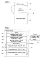
- eine schematische Darstellung eines Speichers einer Positionsmesseinrichtung, in dem neben einer Grundkonfiguration weitere Konfigurationen abgelegt sind;
- Fig. 3
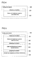
- ein Konfigurationsskript, welches eine Umprogrammierung der Positionsmesseinrichtung hinsichtlich der jeweils aktiven Konfiguration ermöglicht;
- Fig. 4
- einen Konfigurationsblock, mit dem eine bestimmte Konfiguration auf der Positionsmesseinrichtung aktivierbar ist;
- Fig. 5
- eine Abwandlung des Konfigurationsblockes aus
Figur 4 ; - Fig. 6
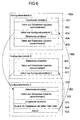
- ein mögliches Zusammenspiel unterschiedlicher Konfigurationsblöcke.
- In
Figur 1 ist eine Positionsmesseinrichtung 1 dargestellt, die als Komponenten in bekannter Weise unter anderem einen Messwertaufnehmer 10 und einen Speicher 15, zum Beispiel in Form eines EEPROM, aufweist. - Der Messwertaufnehmer 10 dient zur Erzeugung von Positionsmesswerten, zum Beispiel, indem die Änderung der Lage zweier Objekte zueinander erfasst wird. Hierzu kann der Messwertaufnehmer eine Maßverkörperung und eine zugeordnete Abtasteinheit umfassen, die jeweils einem der beiden zueinander bewegbaren Objekte zugeordnet sind. Durch Abtastung der Maßverkörperung mittels der hierfür vorgesehenen Abtasteinheit generiert der Messwertaufnehmer ein Ausgangssignal, welches die Position des einen Objektes bezüglich des anderen Objektes widerspiegelt und welches in der Positionsmesseinrichtung üblicherweise noch aufbereitet wird, bevor es zur weiteren Verarbeitung und Auswertung an eine Auswerteeinheit 2 übertragen wird.
- Die Positionsmesseinrichtung 1 kann insbesondere als ein Längenmessgerät oder ein Winkelmessgerät ausgebildet sein, worauf es jedoch vorliegend nicht ankommt. Dies gilt in gleicher Weise für das zur Abtastung einer Maßverkörperung genutzte Messprinzip (zum Beispiel elektro-optisch, induktiv oder magnetisch) und für die Art der generierten Positionsmesswerte (mit inkrementaler oder absoluter Positionsinformation).
- Vorliegend geht es vielmehr um die Konfiguration der Positionsmesseinrichtung 1, welche durch einen Satz an Parameterdaten definiert und festgelegt ist. Dies betrifft beispielsweise die Art der Schnittstelle, über die die Positionsmesseinrichtung 1 mit einer zugeordneten Verarbeitungseinheit 2 über Verbindungsleitungen 25 zusammenwirkt, sowie die Auflösung der von der Positionsmesseinrichtung durchführbaren Positionsmessungen. Weitere Beispiele für Eigenschaften der Positionsmesseinrichtung 1, die durch deren Konfiguration festgelegt werden, sind das Ausgabeformat der Positionsmesswerte und der Inhalt eines elektronischen Typenschilds. Darüber hinaus können in Abhängigkeit von der Konfiguration der Positionsmesseinrichtung 1 bestimmte Funktionen aktiviert oder deaktiviert sein, wie etwa die Ausgabe von Zusatzinformationen (z.B. Messwerte von Zusatzsensoren betreffend Temperatur und/oder Beschleunigung) und deren Datenformat, die Abarbeitung von Zusatzfunktionen (z.B. betreffend Diagnosemöglichkeiten und Sicherheitseinstellungen), die zusätzliche Erzeugung analoger Ausgangssignale, die Nutzung von Kompensationsmechanismen (z.B. Amplituden-, Offset- und/oder Phasenkorrektur) usw.
- Zur Definition bzw. Festlegung einer Konfiguration, mit der die Positionsmesseinrichtung 1 arbeitet, sind die erforderlichen Parameterdaten in dem Speicher 15 der Positionsmesseinrichtung 1 hinterlegt. So wird regelmäßig vom Hersteller einer Positionsmesseinrichtung eine bestimmte Konfiguration eingestellt, mit der die Positionsmesseinrichtung ausgeliefert wird und in Betrieb genommen werden kann.
- In Abhängigkeit von dem konkreten Einsatz der Positionsmesseinrichtung, zum Beispiel der Art der hiermit durchzuführenden Messungen, den Umgebungsbedingungen sowie des Typs einer hieran anzuschließenden Verarbeitungseinheit, kann es gewünscht sein, eine Positionsmesseinrichtung mit einer von der ursprünglich vorgesehenen Konfiguration abweichenden Konfiguration zu betreiben, zum Beispiel, um die Positionsmesseinrichtung über eine andere Schnittstelle mit einer Verarbeitungseinheit verbinden zu können oder um Positionsmessungen mit einer anderen Auflösung durchführen zu können.
- Zu diesem Zweck sind vorliegend im Speicher 15 der Positionsmesseinrichtung 1 neben der ursprünglich vom Hersteller programmierten Grundkonfiguration weitere Daten und Befehle hinterlegt, mittels derer zusätzlich zu der vom Hersteller vorgesehenen Grundkonfiguration noch mindestens eine weitere Konfiguration, insbesondere eine Mehrzahl weiterer Konfigurationen, der Positionsmesseinrichtung erzeugbar/aktivierbar ist. Dies sei nachfolgend anhand
Figur 2 näher erläutert. - Hiernach ist in dem Speicher 15 der Positionsmesseinrichtung 1, zusätzlich zu der vom Hersteller programmierten, ursprünglich aktiven Konfiguration 16, ein Konfigurationsskript 18 vorgesehen, welches diejenigen Daten und Befehle enthält, mittels welcher anstelle der Grundkonfiguration 16 mindestens eine hiervon verschiedene, weitere Konfiguration aktivierbar ist, mit der die Positionsmesseinrichtung betrieben werden kann. Das Konfigurationsskript 18 kann bei Bedarf in verschlüsselter Form im Speicher der Positionsmesseinrichtung 1 abgelegt sein.
- Die zum Konfigurationsskript 18 gehörenden Befehle bilden einen Programmcode, durch dessen Abarbeitung, wie nachfolgend anhand der
Figuren 3 bis 6 in verschiedenen Ausgestaltungen beschrieben werden wird, die Grundkonfiguration 16 der Positionsmesseinrichtung 1 durch eine andere, hiervon verschiedene Konfiguration ersetzbar ist. Hierfür enthält das Konfigurationsskript 18 neben den erforderlichen Befehlen auch diejenigen Daten, welche mittels jener Befehle zur Bildung einer neuen aktiven Konfiguration der Positionsmesseinrichtung in die für die jeweils aktive Konfiguration vorgesehenen Bereiche des Speichers 15 kopiert werden. - Weiterhin ist in dem Speicher 15 der Positionsmesseinrichtung 1 ein Informationssystem, vorliegend in Form eines Objektverzeichnisses 18a hinterlegt, welches angibt, ob in dem Speicher 15 ein Konfigurationsskript 18 hinterlegt ist, und welches gegebenenfalls den Speicherbereich bezeichnet, in welchem das Konfigurationsskript 18 hinterlegt ist.
- Das Konfigurationsskript 18 enthält wiederum - zusätzlich zu den Daten und Befehlen, mit denen die einzelnen weiteren Konfigurationen aktivierbar bzw. erzeugbar sind - ein Inhaltsverzeichnis, in dem die optional aktivierbaren weiteren Konfigurationen aufgeführt sind.
- Zur Aktivierung einer von der Grundkonfiguration 16 verschiedenen, weiteren Konfiguration der Positionsmesseinrichtung 1 wird das Konfigurationsskript in bestimmter Weise abgearbeitet, und zwar so, dass die aktuell aktive Konfiguration durch eine vorbestimmte andere, weitere Konfiguration ersetzt wird. Hierzu kann, wie in
Figur 1 angedeutet, eine Programmiereinheit 3 (über Verbindungsleitungen 35) an die Positionsmesseinrichtung 1 angeschlossen werden. - Alternativ zur Nutzung separater Verbindungsleitungen 35 für den Anschluss der Programmiereinheit 3 könnte die Programmiereinheit 3 auch über diejenigen Verbindungsleitungen 25 (Schnittstelle) an die Positionsmesseinrichtung 1 angeschlossen werden, welche im Übrigen der Verbindung zwischen Positionsmesseinrichtung 1 und Verarbeitungseinheit 2 dienen (und über welche im Messbetrieb die jeweiligen Messwerte übertragen werden). Der Programmierbetrieb (Programmiermodus) ließe sich dann durch einen speziellen Schnittstellenbefehl oder eine Spezialfunktion aktivieren. Bei dieser Variante wäre die Programmiereinheit 3 auch durch ein Datenverarbeitungsprogramm (Software) in der Verarbeitungseinheit realisierbar.
- Die Programmiereinheit 3 stellt insbesondere einen Prozessor 30 (zum Beispiel in Form eines Mikroprozessors) zur Verfügung, mittels dem das im Speicher 15 der Positionsmesseinrichtung 1 hinterlegte Konfigurationsskript 18 zur Änderung der aktiven Konfiguration der Positionsmesseinrichtung 1 abarbeitbar bzw. ausführbar ist.
- Die Verwendung einer zusätzlichen Programmiereinheit 3 zum Abarbeiten des im Speicher 15 der Positionsmesseinrichtung 1 hinterlegten Konfigurationsskriptes ist deshalb erforderlich, weil die Positionsmesseinrichtung 1 selbst nicht über einen Prozessor verfügt, mit dem das Konfigurationsskript 18 abarbeitbar wäre.
- Es ist zwar auch möglich, die Positionsmesseinrichtung 1 mit einem solchen Prozessor auszustatten; dies wäre jedoch mit einem erheblichen zusätzlichen Aufwand sowie zusätzlichen Kosten bei der Herstellung einer Positionsmesseinrichtung verbunden. Die vorliegend vorgeschlagene Ausgestaltung der Positionsmesseinrichtung 1, wie anhand der
Figuren 1 und2 beschrieben, ermöglicht es demgegenüber gerade, mit nur einer Programmiereinheit 3 eine Mehrzahl verschiedener, auch unterschiedlich konfigurierter Positionsmesseinrichtungen (ohne eigenen Prozessor) in einfacher Weise neu zu konfigurieren. - Dabei ist es nicht erforderlich, in einer Programmiereinheit 3, mittels der die Konfiguration einer bestimmten Positionsmesseinrichtung 1 geändert werden soll, ein spezielles, auf eine jeweilige Positionsmesseinrichtung zugeschnittenes Programm vorzusehen. Vielmehr sind die hierfür erforderlichen Daten und Befehle bereits in der jeweiligen Positionsmesseinrichtung 1 selbst hinterlegt, wie vorstehend anhand der
Figuren 1 und2 beschrieben. - Dies bedeutet auch, dass die Programmiereinheit 3 bei der Erzeugung einer neuen Konfiguration in einer jeweiligen Positionsmesseinrichtung 1 nicht auf externe Datenquellen, wie zum Beispiel Datenbanken, zurückgreifen muss; denn die für eine Aktivierung einer neuen Konfiguration der Positionsmesseinrichtung 1 erforderlichen Daten sind ja ebenfalls bereits in letzterer hinterlegt (zusammen mit den hierbei abzuarbeitenden Befehlen).
- Ein Beispiel für ein Konfigurationsskript 18 ist in
Figur 3 gezeigt. Das Inhaltsverzeichnis dieses Konfigurationsskriptes 18 enthält im Ausführungsbeispiel drei Einträge 181, 182, 183, von denen ein jeder eine bestimmte weitere Konfiguration bezeichnet, die im Rahmen des Konfigurationsskriptes 18 aktivierbar sein soll. Zu jeder dieser drei Konfigurationen ist in dem Konfigurationsskript 18 ein so genannter Konfigurationsblock 186, 187, 188 hinterlegt (gespeichert), der die zur Aktivierung der entsprechenden weiteren Konfiguration erforderlichen Daten und Befehle enthält. Vorliegend unterscheiden sich die drei weiteren Konfigurationen jeweils hinsichtlich der Auflösung (10 nm bzw. 50 nm oder 100 nm), mit der unter der jeweiligen Konfiguration die Positionsmessungen durchgeführt werden. - Wird an eine Positionsmesseinrichtung 1, die ein Konfigurationsskript 18 der in
Figur 3 gezeigten Art enthält, eine Programmiereinheit 3 mit Tastatur und Display 32 angeschlossen, wie inFigur 1 dargestellt, so erscheint auf dem Display 32 der Programmiereinheit ein Auswahlmenü, welches die Konfigurationsmöglichkeiten des in der Positionsmesseinrichtung hinterlegten Konfigurationsskriptes 18 zusammenfasst, und zwar auf der Grundlage des zum Konfigurationsskript gehörenden Inhaltsverzeichnisses mit den Einträgen 181, 182, 183. Mit anderen Worten ausgedrückt, dient eine jeweilige Bezeichnung der einzelnen Konfigurationen in den Einträgen 181, 182, 183 des Inhaltsverzeichnisses des Konfigurationsskriptes 18 zugleich auch als Menüzeile für die Darstellung eines entsprechenden Auswahlmenüs auf dem Bildschirm 32 der Programmiereinheit 3. - Dabei ist im Ausführungsbeispiel den einzelnen Konfigurationen jeweils ein Zugriffscode zugeordnet, so dass ein Zugriff auf die einzelnen Konfigurationen auf bestimmte Nutzer beschränkt sein kann. Vorliegend sei angenommen, dass derjenige Nutzer, der gemäß
Figur 3 mit einer Programmiereinheit 3 eine Umprogrammierung der Positionsmesseinrichtung 1 durch Aktivierung einer anderen Konfiguration vornehmen möchte, lediglich auf die ersten beiden Konfigurationen bzw. die zugehörigen Einträge 181, 182 im Inhaltsverzeichnis und die entsprechenden Konfigurationsblöcke 186, 187 zugreifen kann. In diesem Fall werden auf dem Display 32 der Programmiereinheit lediglich die ersten beiden Einträge 181, 182 des in der Positionsmesseinrichtung hinterlegten Inhaltsverzeichnisses in einem Auswahlmenü wiedergegeben, entsprechend einer Konfiguration mit der Auflösung 10 nm oder 50 nm. - Für die Durchführung dieses ersten Schrittes bei der Aktivierung einer neuen Konfiguration der Positionsmesseinrichtung 1 ist es lediglich erforderlich, dass die Programmiereinheit 3 in der Lage ist, die relevanten Daten des Inhaltsverzeichnisses des in der Positionsmesseinrichtung 1 hinterlegten Konfigurationsskriptes 18 auszulesen.
- Über einen Block 185 ("Menü-Auswahl") des Konfigurationsskriptes 18 kann sodann mittels der Programmiereinheit 3 eine der beiden zur Verfügung stehenden und auf dem Display 32 dargestellten Konfigurationen ausgewählt werden.
- Nach Auswahl einer der Konfigurationen mittels der Programmiereinheit wird sodann der entsprechende Konfigurationsblock (186 oder 187) abgearbeitet, indem unter Anwendung der zu dem Konfigurationsblock gehörenden Befehle die ebenfalls zu dem Konfigurationsblock gehörenden Daten in denjenigen Bereich des Speichers 15 der Positionsmesseinrichtung 1 kopiert werden, in welchem jeweils diejenige Konfiguration abzulegen ist, unter welcher die Positionsmesseinrichtung 1 aktuell betrieben werden soll. Hierbei werden, soweit erforderlich, Daten der zuletzt in diesem Speicherbereich befindlichen (anderen) Konfigurationen überschrieben.
- Zur Durchführung dieses weiteren Verfahrensschrittes ist die Programmiereinheit 3 eingerichtet (programmiert), mittels ihres Prozessors 30 diejenigen Befehle auszuführen, die zu dem entsprechenden Konfigurationsblock (186 oder 187) gehören.
- Somit kann eine einzelne Programmiereinheit genutzt werden, um ganz unterschiedliche Positionsmesseinrichtungen durch Änderung der jeweils aktiven Konfiguration umzuprogrammieren. Es ist lediglich erforderlich, dass die Programmiereinheit in der Lage ist, das Inhaltsverzeichnis eines in der jeweiligen Positionsmesseinrichtung hinterlegten Konfigurationsskriptes zu lesen und ggf. für einen Nutzer in Form eines Menüs auf dem eigenen Bildschirm anzuzeigen (sofern die Auswahl einer Konfiguration nicht automatisiert erfolgen soll). Weiterhin muss die Programmiereinheit in der Lage sein, mittels ihres Prozessors die zu einer jeweiligen Konfiguration des Konfigurationsskriptes gehörenden Befehle auszuführen, derart, dass die zu der ausgewählten Konfiguration gehörenden Daten in einen Speicherbereich der Positionsmesseinrichtung kopiert werden, welcher für die aktuell aktive Konfiguration vorgesehen ist.
- In einer ersten Ausführungsform erfolgt die Aktivierung einer neuen Konfiguration, wie in
Figur 4 dargestellt, in der Weise, dass im Rahmen des abzuarbeitenden Konfigurationsblockes (z.B. 186) in einem ersten Schritt 201 die Zieladresse für die zu kopierenden Daten eingestellt wird und anschließend die Daten auf diese Zieladresse, das heißt, in den für die jeweils aktive Konfiguration vorgesehenen Speicherbereich, kopiert werden, gemäß dem Schritt 202. Dabei werden die zuvor in jenem Speicherbereich befindlichen Daten überschrieben. - Eine weitere mögliche Ausgestaltung und Abarbeitung eines Konfigurationsblockes 186 ist in
Figur 5 dargestellt. Gemäß diesem Ausführungsbeispiel braucht der Konfigurationsblock nicht sämtliche Daten zu enthalten, die zu der entsprechenden Konfiguration gehören. Vielmehr enthält der Konfigurationsblock nur diejenigen Daten, in denen sich die hiermit zu aktivierende Konfiguration von einer anderen möglichen Konfiguration (Bezugskonfiguration) der Positionsmesseinrichtung unterscheidet. Ist die letztgenannte Konfiguration aktuell aktiviert, so kann die ausgewählte neue Konfiguration in sehr einfacher Weise dadurch erzeugt werden, dass nur diejenigen Daten der zuletzt aktiven Konfiguration überschrieben werden, in denen sich die neue Konfiguration von letzterer unterscheidet. Hierdurch kann eine jeweilige Konfiguration bzw. der zugehörige Konfigurationsblock mit den zur Aktivierung der Konfiguration benötigten Daten und Befehlen Speicherplatz-sparend in der Positionsmesseinrichtung abgelegt werden. - Als Bezugs-Konfiguration eignet sich dabei z.B. eine Grundkonfiguration, die bei erstmaliger Inbetriebnahme der Positionsmesseinrichtung (z. B. herstellerseitig) bereits aktiviert worden ist. Für alle weiteren (von jener Grundkonfiguration verschiedenen) Konfigurationen, die in der Positionsmesseinrichtung als potentiell aktivierbar hinterlegt werden sollen, müssen dann jeweils nur diejenigen Daten gespeichert werden, in denen sich die jeweilige weitere Konfiguration von der Grundkonfiguration unterscheidet, sowie diejenigen Befehle, mit denen jene Daten in die entsprechenden Speicherbereiche kopiert werden können, wobei jeweils Parameterdaten der Grundkonfiguration zur Bildung neuer aktiver Parameterdaten überschrieben werden.
- Letzteres ist in
Figur 5 illustriert, wonach in drei Verfahrensschritten 301, 303 und 305 jeweils unterschiedliche Zieladressen bzw. unterschiedliche Teilbereiche des Speichers 15 (vergl.Fig. 1 ) ausgewählt werden, wohin Daten der neu zu aktivierenden Konfigurationen kopiert werden sollen, um gezielt bestimmte Parameterdaten der bisherigen Konfiguration zu überschreiben, gemäß den entsprechenden Schritten 302, 304 und 306. Dabei wird vor der Durchführung dieser Kopierschritte 302, 304, 306 die Zieladresse in den zuvor erwähnten Schritten 301, 303, 305 jeweils derart eingestellt (bzw. versetzt), dass die Daten der neu zu aktivierenden Konfiguration jeweils in den richtigen, hierfür vorgesehenen Teilbereich des Speichers 15 geschrieben werden. - Eine Besonderheit besteht dabei noch bezüglich des letzten Kopierschrittes 306. In diesem Kopierschritt wird ein bestimmter Teilbereich des Speichers an allen Speicherplätzen mit demselben Datum beschrieben. In diesem Fall genügt es, wenn das entsprechende Datum als Bestandteil des Konfigurationsblockes 186 einmal abgespeichert ist. Es wird dann über entsprechende Befehle des Konfigurationsblockes 186 auf alle Speicherplätze des betreffenden Teilbereiches des Speichers kopiert. Hierdurch kann der Speicherbedarf der einzelnen Konfigurationsblöcke nochmals reduziert werden. Mit anderen Worten ausgedrückt, wird ein einzelnes Datum aus dem Konfigurationsblock 186 mehrfach in denjenigen Speicherbereich der Positionsmesseinrichtung kopiert, in welchem die jeweils aktive Konfiguration zu hinterlegen ist, so dass ein Teilbereich jenes Speicherbereiches mehrfach (an mehreren Speicherplätzen) mit jenem Datum belegt ist.
- Wenn für eine oder mehrere weitere Konfigurationen, wie anhand
Figur 5 beschrieben, jeweils eine andere Konfiguration, insbesondere die Grundkonfiguration, als eine Bezugskonfiguration gewählt wird, die jeweils nur in Teilen zu ändern ist, um eine neu ausgewählte weitere Konfiguration zu aktivieren, so ist diese Bezugskonfiguration (insbesondere in Form der Grundkonfiguration) jeweils in dem für die aktuell aktive Konfiguration vorgesehenen Speicherbereich der Positionsmesseinrichtung 1 zu hinterlegen, bevor hieraus durch die entsprechenden Änderungen die aktuell ausgewählte weitere Konfiguration erzeugt werden kann. Hierzu kann beispielsweise vorgesehen sein, vor jeder Aktivierung einer neuen Konfiguration zunächst die Bezugskonfiguration (also insbesondere die Grundkonfiguration) zu aktivieren, also in dem für die jeweils aktive Konfiguration vorgesehenen Speicherbereich zu hinterlegen. - Dies kann in einfacher Weise dadurch ermöglicht werden, dass die Bezugskonfiguration/Grundkonfiguration nicht nur anfänglich in dem für die jeweils aktive Konfiguration vorgesehenen Speicherbereich der Positionsmesseinrichtung hinterlegt wird, sondern zusätzlich auch einmal in dem für die optional aktivierbaren weiteren Konfigurationen vorgesehenen Speicherbereich. Hierdurch lässt sich die Bezugskonfiguration/Grundkonfiguration immer wieder erneut herstellen, so dass zur Erzeugung der weiteren Konfigurationen dann jeweils nur die Differenzdaten bezogen auf die Bezugskonfiguration/Grundkonfiguration vorhanden sein müssen, sowie die zum Kopieren dieser Daten vorgesehenen Befehle.
- In dem in
Figur 6 gezeigten Ausführungsbeispiel greifen zwei unterschiedliche Konfigurationsblöcke 186a, 186b bei ihrer Abarbeitung jeweils auf den gleichen Unterblock 189 zu. Der Zugriff mehrerer unterschiedlicher Konfigurationsblöcke 186a, 186b, ... auf ein und denselben Unterblock 189 ist dann zweckmäßig, wenn die unterschiedlichen Konfigurationsblöcke 186a, 186b, ... bei ihrer Abarbeitung jeweils teilweise identische Schritte auszuführen haben. Diese können dann in dem besagten Unterblock 189 zusammengefasst werden. - Vorliegend ist der Unterblock 189 so ausgeführt, dass bei seiner Abarbeitung Schritten 501 bzw. 503 jeweils unterschiedliche Teilbereiche desjenigen Speicherbereiches adressiert werden, in dem die jeweils zu aktivierende Konfiguration abgelegt wird, und dass hierauf folgend jeweils in einem weiteren Schritt 502 bzw. 504 Daten in den entsprechenden Teilbereich kopiert werden. Anschließend wird gemäß einem Schritt 505 die Fortsetzung der Abarbeitung desjenigen Konfigurationsblockes 186a bzw. 186b ausgelöst, der zuvor in einem Schritt 403 den Unterblock 189 aufgerufen hatte.
- Jene beiden Konfigurationsblöcke 186a und 186b unterscheiden sich im Ausführungsbeispiel dadurch, dass bei Abarbeitung des einen Konfigurationsblockes 186a sowohl vor als auch nach Aufruf des Unterblockes 189 jeweils noch andere Schritte 401, 402 bzw. 404, 405 durchzuführen sind, während im Fall des anderen Konfigurationsblockes 186b lediglich vor dem Aufruf des Unterblockes 189 noch andere Verfahrensschritte 401, 402 durchgeführt werden.
- Die genannten Verfahrensschritte 401, 402, 404, 405 bestehen dabei im Ausführungsbeispiel wiederum darin, dass bestimmte Teilbereiche des für die zu aktivierende Konfiguration vorgesehenen Speicherbereiches adressiert und mit Daten der zu aktivierenden Konfiguration belegt werden. Durch die Zusammenfassung von Verfahrensschritten 501 bis 504, die bei der Abarbeitung unterschiedlicher Konfigurationsblöcke 186a, 186b auftreten können, zu einem Unterblock, wird der Speicherplatzbedarf des Konfigurationsskriptes 18 weiter reduziert.
- Zusammenfassend stellen die Konfigurationsblöcke, welche jeweils eine potentiell aktivierbare Konfiguration einer Positionsmesseinrichtung 1 definieren, eine Kombination aus einem durch eine Mehrzahl Befehle gebildeten Programmcode sowie den mit diesem Programmcode zu verarbeitenden Daten dar. Zu den Befehlen gehören dabei zunächst insbesondere Kopierbefehle, mit denen die zu einem bestimmten Konfigurationsblock bzw. der entsprechenden Konfiguration gehörenden Daten in denjenigen Speicherbereich der Positionsmesseinrichtung kopiert werden können, in dem die aktuell aktive Konfiguration zu hinterlegen ist. Weitere relevante Befehle sind etwa vorgesehen zur Bestimmung einer Zieladresse im Speicher, zum Springen auf andere Blöcke ("Jump"), zum Aufrufen anderer Blöcke ("Call"), für den Rücksprung ("Return"), zur Kennzeichnung eines Sprungzieles, zur Ausführung bedingter Sprünge (für das Auswerten einfacher Variablen) sowie zur Prüfung bzw. Berichtigung von CRCs bzw. Checksummen.
- Die Programmiereinheit 3 bildet dabei einen zugehörigen Interpreter, der in der Lage sein muss, die im Konfigurationsskript der Positionsmesseinrichtung 1 gespeicherten Daten zu lesen sowie die dort abgelegten Befehle auszuführen.
- Die vorstehend beschriebene technische Lösung kann auch auf bereits existierende Positionsmesseinrichtungen angewandt werden; es ist lediglich erforderlich, dass diese einen Speicher aufweisen, in dem ein Konfigurationsskript ablegbar ist.
- Dabei kann jene Lösung für ganz unterschiedliche Positionsmesseinrichtungen mit einer universellen Programmiereinheit umgesetzt werden. Diese muss lediglich in der Lage sein, die (im Inhaltsverzeichnis des Konfigurationsskriptes aufgeführten) Konfigurationsmöglichkeiten nach einem geräteunabhängigen (einmal definierten) Verfahren aus dem Speicher des jeweiligen Positionsmessgerätes auszulesen und sodann eine Neuprogrammierung der Konfiguration der Positionsmesseinrichtung unter Anwendung der im Speicher der Positionsmesseinrichtung selbst hinterlegten Befehle und Daten vorzunehmen.
Claims (15)
- Positionsmesseinrichtung mit- einem Messwertaufnehmer (10) zur Durchführung einer Positionsmessung und- mindestens einem Speicher (15), in dem Parameterdaten gespeichert sind, welche eine aktive Konfiguration definieren, mit der die Positionsmesseinrichtung (1) betreibbar ist,dadurch gekennzeichnet,
dass in einem Speicher (15) der Positionsmesseinrichtung (1) Daten und Befehle gespeichert sind, mittels derer mindestens eine weitere Konfiguration aktivierbar ist, mit der die Positionsmesseinrichtung (1) betrieben werden kann. - Positionsmesseinrichtung nach Anspruch 1, dadurch gekennzeichnet, dass die einer jeweiligen weiteren Konfiguration zugeordneten, im Speicher (15) der Positionsmesseinrichtung (1) gespeicherten Daten ausreichend sind zur Aktivierung der jeweiligen weiteren Konfiguration, ohne dass hierfür auf zusätzliche Daten aus einer externen Datenquelle zurückgegriffen werden müsste.
- Positionsmesseinrichtung nach einem der vorhergehenden Ansprüche, dadurch gekennzeichnet, dass für mindestens eine weitere Konfiguration nur ein Teil der Daten, welche diese Konfiguration definieren, im Speicher (15) der Positionsmesseinrichtung (1) gespeichert ist und dass zur Aktivierung dieser Konfiguration in dem Speicher (15) abgelegte Daten mindestens einer anderen Konfiguration genutzt werden.
- Positionsmesseinrichtung nach Anspruch 3, dadurch gekennzeichnet, dass zur Aktivierung der weiteren Konfiguration, für die nur ein Teil der Daten im Speicher (15) der Positionsmesseinrichtung (1) gespeichert ist, die aktuell aktive Konfiguration der Positionsmesseinrichtung (1) nur teilweise mit den Daten der zu aktivierenden weiteren Konfiguration zu überschreiben ist.
- Positionsmesseinrichtung nach einem der vorhergehenden Ansprüche, dadurch gekennzeichnet, dass zur Aktivierung einer weiteren Konfiguration zusätzlich auf Daten aus einem Konfigurationsblock (189) zuzugreifen ist, welcher ebenfalls im Speicher (15) der Positionsmesseinrichtung (1) gespeichert ist und auf den zur Aktivierung einer Mehrzahl unterschiedlicher weiterer Konfigurationen zugegriffen werden kann.
- Positionsmesseinrichtung nach einem der vorhergehenden Ansprüche, dadurch gekennzeichnet, dass die zur wahlweisen Aktivierung einer Mehrzahl unterschiedlicher weiterer Konfigurationen vorgesehenen Daten und Befehle zu einem Konfigurationsskript (18) zusammengefasst sind und dass in einem Inhaltsverzeichnis (181, 182, 183) des Konfigurationsskriptes (18) die aktivierbaren weiteren Konfigurationen bezeichnet sind.
- Positionsmesseinrichtung nach einem der vorhergehenden Ansprüche, dadurch gekennzeichnet, dass mindestens einer weiteren Konfiguration ein Zugriffscode zugeordnet ist, um Beschränkungen hinsichtlich der Nutzer, welche die entsprechende weitere Konfiguration aktivieren können, zu ermöglichen.
- Positionsmesseinrichtung nach einem der vorhergehenden Ansprüche, dadurch gekennzeichnet, dass zur Aktivierung der besagten weiteren Konfiguration an die Positionsmesseinrichtung (1) eine Programmiereinheit (3) anschließbar ist.
- Programmierbares System, umfassend eine Positionsmesseinrichtung (1) nach einem der Ansprüche 1 bis 8 und eine an die Positionsmesseinrichtung (1) anschließbare Programmiereinheit (3).
- Programmierbares System nach Anspruch 9, dadurch gekennzeichnet, dass die Programmiereinheit (3) einen Prozessor (30) aufweist, mit dem die einer jeweiligen weiteren Konfiguration zugeordneten, in einem Speicher (15) der Positionsmesseinrichtung (1) abgelegten Befehle ausführbar sind, um die besagte weitere Konfiguration zu aktivieren.
- Programmierbares System nach Anspruch 9 oder 10 mit einer Positionsmesseinrichtung (1) nach Anspruch 6, dadurch gekennzeichnet, dass die Programmiereinheit (3) ein Display (32) aufweist, auf dem Angaben aus einem dem Konfigurationsskript (18) zugeordneten Inhaltsverzeichnis (18a) als Auswahlmenü anzeigbar sind.
- Programmierbares System nach einem der Ansprüche 9 bis 11, dadurch gekennzeichnet, dass die Programmiereinheit (3) durch ein Datenverarbeitungsprogramm in einer der Positionsmesseinrichtung (1) zugeordneten Verarbeitungseinheit (2), an welche im Messbetrieb der Positionsmesseinrichtung (1) Messewerte übertragen werden, realisiert ist.
- Verfahren zum Programmieren einer Positionsmesseinrichtung (1) nach einem der Ansprüche 1 bis 8, wobeia) an die Positionsmesseinrichtung (1) eine einen Prozessor (30) aufweisende Programmiereinheit (3) angeschlossen wird undb) mittels des Prozessors (30) der Programmiereinheit (3) die einer bestimmten weiteren Konfiguration der Positionsmesseinrichtung (1) zugeordneten Befehle ausgeführt werden, die in einem Speicher (15) der Positionsmesseinrichtung (1) gespeichert sind, um diese Konfiguration zu aktivieren.
- Verfahren nach Anspruch 13, dadurch gekennzeichnet, dass bei Ausführung der Befehle zur Aktivierung der weiteren Konfiguration ausschließlich auf Daten zugegriffen wird, welche im Speicher (15) der Positionsmesseinrichtung (1) gespeichert sind.
- Verfahren nach Anspruch 13 oder 14, dadurch gekennzeichnet, dass die Daten und Befehle mehrerer weiterer Konfigurationen in der Positionsmesseinrichtung (1) zu einem Konfigurationsskript (18) zusammengefasst sind, dem ein Inhaltsverzeichnis (18a) zugeordnet ist, und das in dem Inhaltsverzeichnis (18a) enthaltene Bezeichnungen der aktivierbaren weiteren Konfigurationen auf einem Display (32) der Programmiereinheit (3) angezeigt werden.
Applications Claiming Priority (1)
| Application Number | Priority Date | Filing Date | Title |
|---|---|---|---|
| DE102013208629.6A DE102013208629A1 (de) | 2013-05-10 | 2013-05-10 | Positionsmesseinrichtung |
Publications (3)
| Publication Number | Publication Date |
|---|---|
| EP2801794A2 true EP2801794A2 (de) | 2014-11-12 |
| EP2801794A3 EP2801794A3 (de) | 2015-10-28 |
| EP2801794B1 EP2801794B1 (de) | 2021-10-27 |
Family
ID=50112708
Family Applications (1)
| Application Number | Title | Priority Date | Filing Date |
|---|---|---|---|
| EP14153968.4A Active EP2801794B1 (de) | 2013-05-10 | 2014-02-05 | Positionsmesseinrichtung |
Country Status (6)
| Country | Link |
|---|---|
| US (1) | US11796313B2 (de) |
| EP (1) | EP2801794B1 (de) |
| JP (1) | JP6510766B2 (de) |
| CN (1) | CN104142893B (de) |
| DE (1) | DE102013208629A1 (de) |
| ES (1) | ES2897718T3 (de) |
Cited By (1)
| Publication number | Priority date | Publication date | Assignee | Title |
|---|---|---|---|---|
| EP3086097A1 (de) * | 2015-04-23 | 2016-10-26 | Meggitt (Sensorex) | System zur bewegungsmessung eines mobilen organs, insbesondere eines luftfahrzeugs |
Families Citing this family (3)
| Publication number | Priority date | Publication date | Assignee | Title |
|---|---|---|---|---|
| US9900211B1 (en) * | 2014-10-01 | 2018-02-20 | Crimson Corporation | Systems and methods for network management |
| DE102016200847A1 (de) * | 2016-01-21 | 2017-07-27 | Dr. Johannes Heidenhain Gesellschaft Mit Beschränkter Haftung | Optische Positionsmesseinrichtung |
| EP3315977B1 (de) * | 2016-10-31 | 2025-12-03 | Rohde & Schwarz GmbH & Co. KG | Messvorrichtung für messsignale und datenhandhabungsverfahren |
Citations (1)
| Publication number | Priority date | Publication date | Assignee | Title |
|---|---|---|---|---|
| EP0660209A1 (de) | 1993-12-13 | 1995-06-28 | Dr. Johannes Heidenhain GmbH | Vorrichtung und Verfahren zur seriellen Datenübertragung zwischen einer Positionsmesseinrichtung und einer Verarbeitungseinheit |
Family Cites Families (23)
| Publication number | Priority date | Publication date | Assignee | Title |
|---|---|---|---|---|
| US6347163B2 (en) * | 1994-10-26 | 2002-02-12 | Symbol Technologies, Inc. | System for reading two-dimensional images using ambient and/or projected light |
| JP2788152B2 (ja) * | 1992-06-22 | 1998-08-20 | 松下電器産業株式会社 | バーコードリーダ |
| JP3294737B2 (ja) | 1994-10-13 | 2002-06-24 | ドクトル・ヨハネス・ハイデンハイン・ゲゼルシヤフト・ミツト・ベシユレンクテル・ハフツング | 位置測定装置 |
| EP0790489B1 (de) * | 1996-02-16 | 2000-05-17 | Dr. Johannes Heidenhain GmbH | Vorrichtung und Verfahren zur Umschaltung zwischen verschiedenen Betriebsmodi eines Messwertaufnehmers |
| JPH10103918A (ja) | 1996-09-27 | 1998-04-24 | Tokyo Seimitsu Co Ltd | レーザ測長器 |
| US6907595B2 (en) * | 2002-12-13 | 2005-06-14 | Xilinx, Inc. | Partial reconfiguration of a programmable logic device using an on-chip processor |
| JP2004318439A (ja) * | 2003-04-15 | 2004-11-11 | Sendai Nikon:Kk | エンコーダ装置、ロボットシステム |
| US6799080B1 (en) * | 2003-06-12 | 2004-09-28 | The Boc Group, Inc. | Configurable PLC and SCADA-based control system |
| JP4269322B2 (ja) | 2005-01-18 | 2009-05-27 | 川崎重工業株式会社 | 開先計測方法および開先計測装置 |
| EP1901093B1 (de) * | 2006-09-15 | 2018-11-14 | Triple-IN Holding AG | Aufnahme von Entfernungsbildern |
| KR100941980B1 (ko) * | 2007-11-14 | 2010-02-11 | 한국표준과학연구원 | 고속 대면적 정밀측정 장치 및 방법 |
| EP2063331A1 (de) | 2007-11-21 | 2009-05-27 | Pepperl + Fuchs Gmbh | Sensor für die Automatisierungstechnik und Verfahren zum Konfigurieren eines Sensors |
| JP5251218B2 (ja) | 2008-04-03 | 2013-07-31 | 株式会社ニコン | 測定装置および測定方法 |
| DE102008034318B4 (de) | 2008-07-23 | 2019-08-29 | Robert Bosch Gmbh | Anordnung zur Auswertung der Messwerte eines Messwertwandlers |
| US8581855B2 (en) * | 2008-08-15 | 2013-11-12 | Hexagon Metrology, Inc. | Jogbox for a coordinate measuring machine |
| DE102008053105A1 (de) * | 2008-10-24 | 2010-04-29 | Dr. Johannes Heidenhain Gmbh | Vorrichtung und Verfahren zur Datenübertragung zwischen einem Positionsmessgerät und einer Folgeelektronik |
| JP4783834B2 (ja) | 2009-01-13 | 2011-09-28 | 川崎重工業株式会社 | 開先計測システム |
| GB0906258D0 (en) * | 2009-04-08 | 2009-05-20 | Renishaw Plc | Position encoder apparatus |
| JP5333344B2 (ja) | 2009-06-19 | 2013-11-06 | 株式会社安川電機 | 形状検出装置及びロボットシステム |
| US10168153B2 (en) * | 2010-12-23 | 2019-01-01 | Trimble Inc. | Enhanced position measurement systems and methods |
| US9697331B2 (en) * | 2011-11-01 | 2017-07-04 | Codonics, Inc. | Adaptable information extraction and labeling method and system |
| EP2615423B1 (de) | 2012-01-13 | 2015-10-28 | SICK STEGMANN GmbH | Verfahren zur Prüfung der Funktionsfähigkeit einer digitalen Signalverarbeitungseinheit eines Positionssensors, und Positionskodierer |
| US8843875B2 (en) * | 2012-05-08 | 2014-09-23 | Kla-Tencor Corporation | Measurement model optimization based on parameter variations across a wafer |
-
2013
- 2013-05-10 DE DE102013208629.6A patent/DE102013208629A1/de not_active Withdrawn
-
2014
- 2014-02-05 EP EP14153968.4A patent/EP2801794B1/de active Active
- 2014-02-05 ES ES14153968T patent/ES2897718T3/es active Active
- 2014-05-06 US US14/270,391 patent/US11796313B2/en active Active
- 2014-05-07 CN CN201410191113.4A patent/CN104142893B/zh active Active
- 2014-05-09 JP JP2014097417A patent/JP6510766B2/ja active Active
Patent Citations (1)
| Publication number | Priority date | Publication date | Assignee | Title |
|---|---|---|---|---|
| EP0660209A1 (de) | 1993-12-13 | 1995-06-28 | Dr. Johannes Heidenhain GmbH | Vorrichtung und Verfahren zur seriellen Datenübertragung zwischen einer Positionsmesseinrichtung und einer Verarbeitungseinheit |
Cited By (2)
| Publication number | Priority date | Publication date | Assignee | Title |
|---|---|---|---|---|
| EP3086097A1 (de) * | 2015-04-23 | 2016-10-26 | Meggitt (Sensorex) | System zur bewegungsmessung eines mobilen organs, insbesondere eines luftfahrzeugs |
| FR3035495A1 (fr) * | 2015-04-23 | 2016-10-28 | Meggitt (Sensorex) | Systeme de mesure des deplacements d'un organe mobile notamment d'un aeronef |
Also Published As
| Publication number | Publication date |
|---|---|
| CN104142893B (zh) | 2019-08-23 |
| CN104142893A (zh) | 2014-11-12 |
| JP2014219414A (ja) | 2014-11-20 |
| ES2897718T3 (es) | 2022-03-02 |
| US11796313B2 (en) | 2023-10-24 |
| EP2801794A3 (de) | 2015-10-28 |
| JP6510766B2 (ja) | 2019-05-08 |
| US20140336979A1 (en) | 2014-11-13 |
| DE102013208629A1 (de) | 2014-11-13 |
| EP2801794B1 (de) | 2021-10-27 |
Similar Documents
| Publication | Publication Date | Title |
|---|---|---|
| EP2318920B1 (de) | Steuergerät für ein fahrzeug und verfahren für eine datenaktualisierung für ein steuergerät für ein fahrzeug | |
| DE69213809T2 (de) | Verfahren und Vorrichtung zur Erzeugung von Kalibrierinformationen für ein elektronisches Motorsteuermodul | |
| DE60119412T2 (de) | Speicherüberschreibungssystem für eine Fahrzeugsteuereinrichtung | |
| EP1430369B1 (de) | Dynamischer zugriff auf automatisierungsressourcen | |
| EP2801794B1 (de) | Positionsmesseinrichtung | |
| DE102008010864A1 (de) | Verfahren zum Betreiben eines Feldgerätes | |
| DE102009047544A1 (de) | Verfahren zum Einstellen von Prametern eines Feldgerät-Stromversorgungsmoduls | |
| WO2011042318A1 (de) | Verfahren zur steuerung und bedienung einer produktionszelle sowie eine steuereinrichtung | |
| DE102010064279A1 (de) | Feldgerät mit Langzeit-Firmware-Kompatibilität | |
| EP2181367A1 (de) | Verfahren zum bedienen eines feldgeräts der prozessautomatisierungstechnik mit mindestens zwei messkanälen und feldgerät der prozessautomatisierungstechnik mit mindestens zwei messkanälen, das zur durchführung des verfahrens geeignet ist | |
| DE102014111350A1 (de) | Automatisierte Erstellung von geeigneten Vorzugsmenüs für Feldgeräte | |
| EP3692424B1 (de) | Verfahren zum bearbeiten eines softwareprojekts | |
| DE102010042999A1 (de) | Verfahren zur Bereitstellung eines Bedienmenüs für ein Feldgerät der Prozessautomatisierungstechnik | |
| DE102006062478B4 (de) | Verfahren zum Betreiben eines objektbasierten Konfigurationssystems für Feldgeräte der Automatisierungstechnik | |
| DE10234063B4 (de) | Verfahren zum variantenspezifischen Programmieren eines Programm- und Datenspeichers eines Steuergeräts, insbesondere eines Steuergeräts eines Kraftfahrzeugs, sowie Vorrichtung zur Durchführung des Verfahrens | |
| DE602004013079T2 (de) | Verfahren und Gerät zur Verwaltung und Speicherung nicht volatiler Daten eines Kommunikationsgeräts, zum Beispiel in einem Pico-Netz wie "Bluetooth" | |
| WO2009019108A1 (de) | Verfahren zum erstellen einer software in einem feldgerät durch einen benutzer | |
| EP3396479A1 (de) | Engineering-system | |
| DE102009005902A1 (de) | Verfahren zum Betrieb eines elektrischen Geräts und korrespondierendes elektrisches Gerät | |
| DE112019006886T5 (de) | Systementwicklungsunterstützungsvorrichtung, Verfahren, Programm und Aufzeichnungsmedium | |
| WO2007068563A1 (de) | Verfahren zur verarbeitung und erzeugung von diagnosedaten in einem softwareentwicklungsprozess | |
| EP1821165B1 (de) | Nutzung von Variablen in mehreren Automatisierungssystemen | |
| EP4242758A1 (de) | Gateway und verfahren zur inbetriebnahme eines gateways | |
| EP3528108A1 (de) | Vereinfachte programmerstellung für komponenten von automatisierungssystemen | |
| DE10109365A1 (de) | Vorrichtung zur Erkennung von Funktionseinheiten |
Legal Events
| Date | Code | Title | Description |
|---|---|---|---|
| PUAI | Public reference made under article 153(3) epc to a published international application that has entered the european phase |
Free format text: ORIGINAL CODE: 0009012 |
|
| 17P | Request for examination filed |
Effective date: 20140205 |
|
| AK | Designated contracting states |
Kind code of ref document: A2 Designated state(s): AL AT BE BG CH CY CZ DE DK EE ES FI FR GB GR HR HU IE IS IT LI LT LU LV MC MK MT NL NO PL PT RO RS SE SI SK SM TR |
|
| AX | Request for extension of the european patent |
Extension state: BA ME |
|
| PUAL | Search report despatched |
Free format text: ORIGINAL CODE: 0009013 |
|
| AK | Designated contracting states |
Kind code of ref document: A3 Designated state(s): AL AT BE BG CH CY CZ DE DK EE ES FI FR GB GR HR HU IE IS IT LI LT LU LV MC MK MT NL NO PL PT RO RS SE SI SK SM TR |
|
| AX | Request for extension of the european patent |
Extension state: BA ME |
|
| RIC1 | Information provided on ipc code assigned before grant |
Ipc: G01D 5/244 20060101ALI20150918BHEP Ipc: G06F 17/30 20060101ALI20150918BHEP Ipc: G01D 21/00 20060101AFI20150918BHEP |
|
| R17P | Request for examination filed (corrected) |
Effective date: 20160428 |
|
| RBV | Designated contracting states (corrected) |
Designated state(s): AL AT BE BG CH CY CZ DE DK EE ES FI FR GB GR HR HU IE IS IT LI LT LU LV MC MK MT NL NO PL PT RO RS SE SI SK SM TR |
|
| STAA | Information on the status of an ep patent application or granted ep patent |
Free format text: STATUS: EXAMINATION IS IN PROGRESS |
|
| 17Q | First examination report despatched |
Effective date: 20180322 |
|
| REG | Reference to a national code |
Ref country code: DE Ref legal event code: R079 Ref document number: 502014015944 Country of ref document: DE Free format text: PREVIOUS MAIN CLASS: G01D0005244000 Ipc: G01D0021000000 |
|
| GRAP | Despatch of communication of intention to grant a patent |
Free format text: ORIGINAL CODE: EPIDOSNIGR1 |
|
| STAA | Information on the status of an ep patent application or granted ep patent |
Free format text: STATUS: GRANT OF PATENT IS INTENDED |
|
| RIC1 | Information provided on ipc code assigned before grant |
Ipc: G01D 5/244 20060101ALI20210507BHEP Ipc: G01D 21/00 20060101AFI20210507BHEP |
|
| INTG | Intention to grant announced |
Effective date: 20210602 |
|
| GRAS | Grant fee paid |
Free format text: ORIGINAL CODE: EPIDOSNIGR3 |
|
| GRAA | (expected) grant |
Free format text: ORIGINAL CODE: 0009210 |
|
| STAA | Information on the status of an ep patent application or granted ep patent |
Free format text: STATUS: THE PATENT HAS BEEN GRANTED |
|
| AK | Designated contracting states |
Kind code of ref document: B1 Designated state(s): AL AT BE BG CH CY CZ DE DK EE ES FI FR GB GR HR HU IE IS IT LI LT LU LV MC MK MT NL NO PL PT RO RS SE SI SK SM TR |
|
| REG | Reference to a national code |
Ref country code: GB Ref legal event code: FG4D Free format text: NOT ENGLISH |
|
| REG | Reference to a national code |
Ref country code: CH Ref legal event code: EP |
|
| REG | Reference to a national code |
Ref country code: AT Ref legal event code: REF Ref document number: 1442184 Country of ref document: AT Kind code of ref document: T Effective date: 20211115 |
|
| REG | Reference to a national code |
Ref country code: DE Ref legal event code: R096 Ref document number: 502014015944 Country of ref document: DE |
|
| REG | Reference to a national code |
Ref country code: IE Ref legal event code: FG4D Free format text: LANGUAGE OF EP DOCUMENT: GERMAN |
|
| REG | Reference to a national code |
Ref country code: LT Ref legal event code: MG9D |
|
| REG | Reference to a national code |
Ref country code: NL Ref legal event code: MP Effective date: 20211027 Ref country code: ES Ref legal event code: FG2A Ref document number: 2897718 Country of ref document: ES Kind code of ref document: T3 Effective date: 20220302 |
|
| PG25 | Lapsed in a contracting state [announced via postgrant information from national office to epo] |
Ref country code: RS Free format text: LAPSE BECAUSE OF FAILURE TO SUBMIT A TRANSLATION OF THE DESCRIPTION OR TO PAY THE FEE WITHIN THE PRESCRIBED TIME-LIMIT Effective date: 20211027 Ref country code: LT Free format text: LAPSE BECAUSE OF FAILURE TO SUBMIT A TRANSLATION OF THE DESCRIPTION OR TO PAY THE FEE WITHIN THE PRESCRIBED TIME-LIMIT Effective date: 20211027 Ref country code: FI Free format text: LAPSE BECAUSE OF FAILURE TO SUBMIT A TRANSLATION OF THE DESCRIPTION OR TO PAY THE FEE WITHIN THE PRESCRIBED TIME-LIMIT Effective date: 20211027 Ref country code: BG Free format text: LAPSE BECAUSE OF FAILURE TO SUBMIT A TRANSLATION OF THE DESCRIPTION OR TO PAY THE FEE WITHIN THE PRESCRIBED TIME-LIMIT Effective date: 20220127 |
|
| PG25 | Lapsed in a contracting state [announced via postgrant information from national office to epo] |
Ref country code: IS Free format text: LAPSE BECAUSE OF FAILURE TO SUBMIT A TRANSLATION OF THE DESCRIPTION OR TO PAY THE FEE WITHIN THE PRESCRIBED TIME-LIMIT Effective date: 20220227 Ref country code: SE Free format text: LAPSE BECAUSE OF FAILURE TO SUBMIT A TRANSLATION OF THE DESCRIPTION OR TO PAY THE FEE WITHIN THE PRESCRIBED TIME-LIMIT Effective date: 20211027 Ref country code: PT Free format text: LAPSE BECAUSE OF FAILURE TO SUBMIT A TRANSLATION OF THE DESCRIPTION OR TO PAY THE FEE WITHIN THE PRESCRIBED TIME-LIMIT Effective date: 20220228 Ref country code: PL Free format text: LAPSE BECAUSE OF FAILURE TO SUBMIT A TRANSLATION OF THE DESCRIPTION OR TO PAY THE FEE WITHIN THE PRESCRIBED TIME-LIMIT Effective date: 20211027 Ref country code: NO Free format text: LAPSE BECAUSE OF FAILURE TO SUBMIT A TRANSLATION OF THE DESCRIPTION OR TO PAY THE FEE WITHIN THE PRESCRIBED TIME-LIMIT Effective date: 20220127 Ref country code: NL Free format text: LAPSE BECAUSE OF FAILURE TO SUBMIT A TRANSLATION OF THE DESCRIPTION OR TO PAY THE FEE WITHIN THE PRESCRIBED TIME-LIMIT Effective date: 20211027 Ref country code: LV Free format text: LAPSE BECAUSE OF FAILURE TO SUBMIT A TRANSLATION OF THE DESCRIPTION OR TO PAY THE FEE WITHIN THE PRESCRIBED TIME-LIMIT Effective date: 20211027 Ref country code: HR Free format text: LAPSE BECAUSE OF FAILURE TO SUBMIT A TRANSLATION OF THE DESCRIPTION OR TO PAY THE FEE WITHIN THE PRESCRIBED TIME-LIMIT Effective date: 20211027 Ref country code: GR Free format text: LAPSE BECAUSE OF FAILURE TO SUBMIT A TRANSLATION OF THE DESCRIPTION OR TO PAY THE FEE WITHIN THE PRESCRIBED TIME-LIMIT Effective date: 20220128 |
|
| REG | Reference to a national code |
Ref country code: DE Ref legal event code: R097 Ref document number: 502014015944 Country of ref document: DE |
|
| PG25 | Lapsed in a contracting state [announced via postgrant information from national office to epo] |
Ref country code: SM Free format text: LAPSE BECAUSE OF FAILURE TO SUBMIT A TRANSLATION OF THE DESCRIPTION OR TO PAY THE FEE WITHIN THE PRESCRIBED TIME-LIMIT Effective date: 20211027 Ref country code: SK Free format text: LAPSE BECAUSE OF FAILURE TO SUBMIT A TRANSLATION OF THE DESCRIPTION OR TO PAY THE FEE WITHIN THE PRESCRIBED TIME-LIMIT Effective date: 20211027 Ref country code: RO Free format text: LAPSE BECAUSE OF FAILURE TO SUBMIT A TRANSLATION OF THE DESCRIPTION OR TO PAY THE FEE WITHIN THE PRESCRIBED TIME-LIMIT Effective date: 20211027 Ref country code: EE Free format text: LAPSE BECAUSE OF FAILURE TO SUBMIT A TRANSLATION OF THE DESCRIPTION OR TO PAY THE FEE WITHIN THE PRESCRIBED TIME-LIMIT Effective date: 20211027 Ref country code: DK Free format text: LAPSE BECAUSE OF FAILURE TO SUBMIT A TRANSLATION OF THE DESCRIPTION OR TO PAY THE FEE WITHIN THE PRESCRIBED TIME-LIMIT Effective date: 20211027 |
|
| PLBE | No opposition filed within time limit |
Free format text: ORIGINAL CODE: 0009261 |
|
| STAA | Information on the status of an ep patent application or granted ep patent |
Free format text: STATUS: NO OPPOSITION FILED WITHIN TIME LIMIT |
|
| PG25 | Lapsed in a contracting state [announced via postgrant information from national office to epo] |
Ref country code: MC Free format text: LAPSE BECAUSE OF FAILURE TO SUBMIT A TRANSLATION OF THE DESCRIPTION OR TO PAY THE FEE WITHIN THE PRESCRIBED TIME-LIMIT Effective date: 20211027 |
|
| 26N | No opposition filed |
Effective date: 20220728 |
|
| REG | Reference to a national code |
Ref country code: BE Ref legal event code: MM Effective date: 20220228 |
|
| PG25 | Lapsed in a contracting state [announced via postgrant information from national office to epo] |
Ref country code: LU Free format text: LAPSE BECAUSE OF NON-PAYMENT OF DUE FEES Effective date: 20220205 Ref country code: AL Free format text: LAPSE BECAUSE OF FAILURE TO SUBMIT A TRANSLATION OF THE DESCRIPTION OR TO PAY THE FEE WITHIN THE PRESCRIBED TIME-LIMIT Effective date: 20211027 |
|
| PG25 | Lapsed in a contracting state [announced via postgrant information from national office to epo] |
Ref country code: SI Free format text: LAPSE BECAUSE OF FAILURE TO SUBMIT A TRANSLATION OF THE DESCRIPTION OR TO PAY THE FEE WITHIN THE PRESCRIBED TIME-LIMIT Effective date: 20211027 |
|
| PG25 | Lapsed in a contracting state [announced via postgrant information from national office to epo] |
Ref country code: FR Free format text: LAPSE BECAUSE OF NON-PAYMENT OF DUE FEES Effective date: 20220228 |
|
| PG25 | Lapsed in a contracting state [announced via postgrant information from national office to epo] |
Ref country code: IE Free format text: LAPSE BECAUSE OF NON-PAYMENT OF DUE FEES Effective date: 20220205 |
|
| PG25 | Lapsed in a contracting state [announced via postgrant information from national office to epo] |
Ref country code: BE Free format text: LAPSE BECAUSE OF NON-PAYMENT OF DUE FEES Effective date: 20220228 |
|
| REG | Reference to a national code |
Ref country code: AT Ref legal event code: MM01 Ref document number: 1442184 Country of ref document: AT Kind code of ref document: T Effective date: 20220205 |
|
| PG25 | Lapsed in a contracting state [announced via postgrant information from national office to epo] |
Ref country code: AT Free format text: LAPSE BECAUSE OF NON-PAYMENT OF DUE FEES Effective date: 20220205 |
|
| PG25 | Lapsed in a contracting state [announced via postgrant information from national office to epo] |
Ref country code: HU Free format text: LAPSE BECAUSE OF FAILURE TO SUBMIT A TRANSLATION OF THE DESCRIPTION OR TO PAY THE FEE WITHIN THE PRESCRIBED TIME-LIMIT; INVALID AB INITIO Effective date: 20140205 |
|
| PG25 | Lapsed in a contracting state [announced via postgrant information from national office to epo] |
Ref country code: MK Free format text: LAPSE BECAUSE OF FAILURE TO SUBMIT A TRANSLATION OF THE DESCRIPTION OR TO PAY THE FEE WITHIN THE PRESCRIBED TIME-LIMIT Effective date: 20211027 Ref country code: CY Free format text: LAPSE BECAUSE OF FAILURE TO SUBMIT A TRANSLATION OF THE DESCRIPTION OR TO PAY THE FEE WITHIN THE PRESCRIBED TIME-LIMIT Effective date: 20211027 |
|
| PG25 | Lapsed in a contracting state [announced via postgrant information from national office to epo] |
Ref country code: MT Free format text: LAPSE BECAUSE OF FAILURE TO SUBMIT A TRANSLATION OF THE DESCRIPTION OR TO PAY THE FEE WITHIN THE PRESCRIBED TIME-LIMIT Effective date: 20211027 |
|
| PG25 | Lapsed in a contracting state [announced via postgrant information from national office to epo] |
Ref country code: TR Free format text: LAPSE BECAUSE OF FAILURE TO SUBMIT A TRANSLATION OF THE DESCRIPTION OR TO PAY THE FEE WITHIN THE PRESCRIBED TIME-LIMIT Effective date: 20211027 |
|
| REG | Reference to a national code |
Ref country code: CH Ref legal event code: R17 Free format text: ST27 STATUS EVENT CODE: U-0-0-R10-R17 (AS PROVIDED BY THE NATIONAL OFFICE) Effective date: 20260108 |
|
| REG | Reference to a national code |
Ref country code: CH Ref legal event code: U11 Free format text: ST27 STATUS EVENT CODE: U-0-0-U10-U11 (AS PROVIDED BY THE NATIONAL OFFICE) Effective date: 20260301 |
|
| PGFP | Annual fee paid to national office [announced via postgrant information from national office to epo] |
Ref country code: GB Payment date: 20260219 Year of fee payment: 13 |
|
| PGFP | Annual fee paid to national office [announced via postgrant information from national office to epo] |
Ref country code: DE Payment date: 20260218 Year of fee payment: 13 |
|
| PGFP | Annual fee paid to national office [announced via postgrant information from national office to epo] |
Ref country code: IT Payment date: 20260224 Year of fee payment: 13 |
|
| PGFP | Annual fee paid to national office [announced via postgrant information from national office to epo] |
Ref country code: CH Payment date: 20260301 Year of fee payment: 13 Ref country code: CZ Payment date: 20260127 Year of fee payment: 13 |
|
| PGFP | Annual fee paid to national office [announced via postgrant information from national office to epo] |
Ref country code: ES Payment date: 20260408 Year of fee payment: 13 |