EP2801697B1 - Nicht säulenförmiges abbauverfahren mit langwandiger arbeitsfläche - Google Patents
Nicht säulenförmiges abbauverfahren mit langwandiger arbeitsfläche Download PDFInfo
- Publication number
- EP2801697B1 EP2801697B1 EP12864300.4A EP12864300A EP2801697B1 EP 2801697 B1 EP2801697 B1 EP 2801697B1 EP 12864300 A EP12864300 A EP 12864300A EP 2801697 B1 EP2801697 B1 EP 2801697B1
- Authority
- EP
- European Patent Office
- Prior art keywords
- headentry
- mining
- top panel
- face
- pillared
- Prior art date
- Legal status (The legal status is an assumption and is not a legal conclusion. Google has not performed a legal analysis and makes no representation as to the accuracy of the status listed.)
- Active
Links
- 238000005065 mining Methods 0.000 title claims description 97
- 238000000034 method Methods 0.000 title claims description 49
- 238000005422 blasting Methods 0.000 claims description 21
- 239000003245 coal Substances 0.000 claims description 17
- 230000002457 bidirectional effect Effects 0.000 claims description 8
- 238000000926 separation method Methods 0.000 claims description 5
- 238000005553 drilling Methods 0.000 claims description 3
- 238000012544 monitoring process Methods 0.000 claims description 2
- 230000003014 reinforcing effect Effects 0.000 claims description 2
- 238000011282 treatment Methods 0.000 claims description 2
- 239000011435 rock Substances 0.000 description 18
- 238000005516 engineering process Methods 0.000 description 7
- 230000000717 retained effect Effects 0.000 description 4
- 230000008093 supporting effect Effects 0.000 description 4
- 239000000463 material Substances 0.000 description 3
- 239000002699 waste material Substances 0.000 description 3
- 229920001807 Urea-formaldehyde Polymers 0.000 description 2
- 230000007547 defect Effects 0.000 description 2
- 238000006073 displacement reaction Methods 0.000 description 2
- 239000002360 explosive Substances 0.000 description 2
- 230000007774 longterm Effects 0.000 description 2
- 238000004519 manufacturing process Methods 0.000 description 2
- ODGAOXROABLFNM-UHFFFAOYSA-N polynoxylin Chemical compound O=C.NC(N)=O ODGAOXROABLFNM-UHFFFAOYSA-N 0.000 description 2
- 229920006327 polystyrene foam Polymers 0.000 description 2
- 230000002787 reinforcement Effects 0.000 description 2
- 238000011160 research Methods 0.000 description 2
- 229910000831 Steel Inorganic materials 0.000 description 1
- 230000006399 behavior Effects 0.000 description 1
- 230000002146 bilateral effect Effects 0.000 description 1
- 238000004364 calculation method Methods 0.000 description 1
- 238000006243 chemical reaction Methods 0.000 description 1
- 230000001186 cumulative effect Effects 0.000 description 1
- 238000005520 cutting process Methods 0.000 description 1
- 230000007812 deficiency Effects 0.000 description 1
- 238000013461 design Methods 0.000 description 1
- 238000005474 detonation Methods 0.000 description 1
- 238000011161 development Methods 0.000 description 1
- 230000000694 effects Effects 0.000 description 1
- 238000004880 explosion Methods 0.000 description 1
- 238000007667 floating Methods 0.000 description 1
- 230000014509 gene expression Effects 0.000 description 1
- 238000011065 in-situ storage Methods 0.000 description 1
- 238000009434 installation Methods 0.000 description 1
- 239000002184 metal Substances 0.000 description 1
- 230000000737 periodic effect Effects 0.000 description 1
- 239000011148 porous material Substances 0.000 description 1
- 230000001681 protective effect Effects 0.000 description 1
- 239000010802 sludge Substances 0.000 description 1
- 239000010959 steel Substances 0.000 description 1
- 230000009897 systematic effect Effects 0.000 description 1
Images
Classifications
-
- E—FIXED CONSTRUCTIONS
- E21—EARTH OR ROCK DRILLING; MINING
- E21C—MINING OR QUARRYING
- E21C41/00—Methods of underground or surface mining; Layouts therefor
- E21C41/16—Methods of underground mining; Layouts therefor
- E21C41/18—Methods of underground mining; Layouts therefor for brown or hard coal
Definitions
- the present disclosure relates to a coal seam mining method, and particularly to a longwall working face coal seam mining method.
- a longwall mining usually adopts means of retaining pillars to protect a tailentry roadway.
- the widths of retained pillars are increased due to the rapidly increased ground stress.
- large engineering quantity of roadways, high development ratio, low production efficiency, severe resource waste in the deep mining process, and safety hazards such as gas outbursts, frequent rock bursts and air leakage in the goafs caused by the retained pillars, have become important problems that are disturbing and affecting mine safety and efficiency.
- Goaf-side entry driving refers to the following: after the previous working face extracting is completed, a top panel of the mining face is fully caved, waste rocks are extruded and compacted, the behaviors of the ground pressure in cover rocks stop, and surrounding rocks are stable, a pressure relief zone is formed in the goaf and the edge of coal mass, and a new roadway is driven again in the pressure relief zone.
- entry driving can only be performed after a working face of the previous district sublevel extracting is completed and the top panel of the mining face is completely caved and compacted, and hence a long time is required, thereby resulting in difficult production replacement of many mines in China.
- Goaf-side entry retaining refers to the following: in the extracting process of the working face, a headentry in the working face is retained by relevant technology and taken as a tailentry for extracting of the next working face.
- a headentry in the working face is retained by relevant technology and taken as a tailentry for extracting of the next working face.
- In the current goaf-side entry retaining technology in the aspect of roadway inner support, technology such as wooden shed, I-shaped steel shed, telescopic support and bolt mesh anchor has been developed in succession.
- roadway side support technology such as timber crib, dense pillar, waste pack, concrete block, paste backfilling and high-water-content material refilling has been developed.
- the supporting function of a roadway side coal mass is ignored; there are few applications for active roadway support technology; the roadway side support and the surrounding rock deformation are uncoordinated; and the support design is not systematic.
- ZHANG GUO-FENG et al "Research on the Technique of No-Pillar Mining with Gob-Side Entry Formed by Advanced Roof Caving in the Protective Seam in Baijiao Coal Mine” Journal of Mining & Safety Engineering, CN, vol 28, No 4, 1 December 2011, pages 511-516 (ISSN 1673-3363 ) discloses a technique for non-pillar mining.
- the technique includes the step of pre-splitting the roof by an advanced bilateral cumulative tensile explosion so as to cut off the connection between the roof above the gob-side entry and the immediate and main roofs.
- the gob-side roof cutting is performed under the action of stope periodic weightings.
- US 5,668,325 discloses an apparatus for determining compressive stress in an in-situ roof support pillar.
- the objective of the present disclosure is to overcome the defects in the prior art and provide a longwall working face non-pillared mining method having advantages of reliable support, high mining efficiency and no requirement of pillars.
- the present disclosure provides a longwall working face non-pillared mining method, includes steps of:
- step ii) further includes steps of: mounting a sensor on the top panel of the headentry, and wire-transmitting signals to the ground for remotely real-time monitoring of the status of the headentry.
- An anchor rod with constant resistance and large deformation is adopted in the step ii) to reinforce the top panel of the headentry.
- a bidirectional energy collecting pre-splitting blasting method is adopted in the step iv) to perform a directional kerfing.
- the roadways need also to be subjected to leakproof and fireproof treatments.
- the sensor in the step ii) includes a top panel separation indicator and an anchor rod stress analyzer.
- the longwall working face non-pillared mining method provided by the present disclosure has one or more of the following prominent substantive features and notable progresses.
- the energy collecting holes for pre-splitting blasting are drilled on the working face side of the top panel of the headentry; blasting is performed at the position corresponding to the energy collecting hole; the kerf extending along the original headentry is formed on a side of the top panel close to the mining face; the goaf is caved along the kerf, so that the roadway can be automatically formed at the position of the original headentry; the top panel of the roadway cannot be affected by goaf carving and can be kept in good state; then the roadway is taken as a tailentry of the next mining face, and the next mining process is performed continuously; and every two mining faces are continuous and not supported by pillars.
- the longwall working face non-pillared mining method has prominent substantive features.
- the longwall working face non-pillared mining method provided by the present disclosure achieves the objective of non-pillared support and high coefficient of mining.
- the time of continuous coal seam mining can be reduced under the premise of safety, and hence the longwall working face non-pillared mining method provided by the present disclosure has significant progress compared with the prior art.
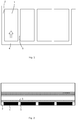
- a first mining face needs to be formed at first.
- the method for forming the first mining face 1 is the same as the traditional method including steps of: determining a primary mining position on a mining edge of a coal seam, and excavating two parallel roadways 2 and 3 at the position by an S100A roadheader.
- the two parallel roadways 2 and 3 are communicated with each other at the tails through a roadway 4.
- the roadway 2 close to the edge is a tailentry; the roadway 3 close to the next mining face is a headentry; and the roadway for communicating the tailentry 2 and the headentry 3 is an extracting face 4.
- Each mining face must be provided with two roadways; the tailentry is a material delivery roadway; and the headentry is an air return roadway.
- the mining process begins from the extracting face 4 until all the coals in areas between the tailentry 2 and the headentry 3 are worked out, and then the next mining face is mined.
- the supporting process includes passive support and active support.
- the passive support is to set up a frame in the headentry 3, and the frame passively bears the pressure from a top panel of the headentry 3.
- the supporting means has the defects of high material consumption, high cost and limited supporting effect.
- the active support is to additionally arrange an anchor rod on the top panel 5 of the headentry 3 to reinforce the top panel 5.
- the anchor rod 6 is usually 5 to 10 m in length and prop the top panel 5 of the headentry 3 by being connected with a relatively stable rock mass on an upper layer.
- the common anchor rod has a small deformation and can be easily broken.
- An anchor rod with constant resistance and a large deformation is adopted for reinforcement in the present disclosure.
- the anchor rod with constant resistance and a large deformation has been disclosed in detail in the patent publication document CN101858225B .
- the anchor rods with constant resistance and large deformation 6 are uniformly distributed on the top panel 5 of the headentry 3 of the first mining face 1, and the spacing is set to be 2 to 5 m as required.
- the anchor rod with constant resistance and large deformation 6 is an anchor rod designed for large-deformation roadways and high-stress roadways, where the constant resistance can be maintained and the elongation is maintained by a mechanical slide means.
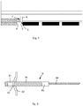
- the anchor rod with constant resistance and large deformation 6 includes a nut 61, a ball pad 62, a tray 63, a constant-resistance device 64, a connecting sleeve 65 and a rod body 66.
- the constant-resistance device 64 has a cylindrical structure and is sleeved at the tail of the rod body 66; the tray 63 and the nut 61 are sleeved at the tail of the constant-resistance device 64 in sequence; a central portion of the tray 63 is provided with a hole through which the constant-resistance device 64 passes; the nut 61 is in a threaded connection with the constant-resistance device 64; the ball pad 62 for buffer is disposed between the nut 61 and the tray 63; and the connecting sleeve is disposed at the other end of the constant-resistance device 64.
- the anchor rod with constant resistance and large deformation 6 can still maintain constant working resistance after extension; when the deformation energy of the surrounding rocks is less than the constant working resistance of the anchor rod with constant resistance and large deformation 6, and the constant-resistance device 64 is restored and tightly sleeved on the rod body 66, the roadway is in a stable state again, and hence the stability of the roadway can be achieved and the safety hazards such as the impact of the top panel falling can be eliminated.
- the bearing capacity of the anchor rod with constant resistance and large deformation 6 is in a range of 15 to 20 KN and the elongation thereof can reach 300 to 600 mm. Therefore, the anchor rod with constant resistance and large deformation 6 has a large deformability so as to be adapted to the high deformability of goaf roadways.
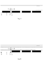
- energy collecting holes 7 linearly arranged are drilled up on the top panel 5 of the headentry 3 of the first mining face 1, close to a side of the first mining face, in sequence by an MQT-120J drill, so that the blasting process can be conveniently achieved by the energy collecting holes 7 and hence the directional kerf can be achieved.
- the pitch of the energy collecting holes 7 is 2 to 5 m and determined by the characteristics of actual strata.
- the roadways 2, 3 and 4 need also to be sprayed with urea-formaldehyde polystyrene foam for leakage resistance and fire resistance.
- a top panel separation indicator and an anchor rod stress analyzer are also disposed on the top panel 5 of the headentry 3 of the first mining face, and shape and position sensors may be also mounted at a corresponding position of the side wall and bottom surface of the headentry 3.
- the top panel separation indicator is mounted on the top panel 5 and can detect the variation of the relative displacement of a determined near point relative to a determined far point, so as to monitor the fall state of the top panel 5;
- the anchor rod stress analyzer is mounted on the top panel 5 through the anchor rod 6 and can detect the pressure of the top panel 5 on a top face of the tray 63 of the anchor rod with constant resistance and large deformation 6, so as to monitor the variation of the fall pressure of the top panel 5;
- the shape and position sensors are respectively mounted on the top panel 5, the bottom surface and two side walls of the headentry 3 and configured to monitor the variation of the cross-sectional shape of the headentry 3.
- Signals monitored by the top panel separation indicator, the anchor rod stress analyzer and the shape and position sensors are all transmitted to the ground through a wire and subjected to data conversion on the ground; converted data are remotely transmitted by means of Ethernet and the like; hence workers can remotely monitor and analyze the data, so as to remotely monitor the state of the headentry 3 in real time.
- the mining face is gradually extracted until a goaf is formed.
- a side wall on a side of the headentry 3 of the first mining face 1 is eliminated; the headentry 3 and the goaf are merged together; and the roadway is eliminated.
- a bidirectional energy collecting pre-splitting blasting device is mounted at the position corresponding to energy collecting holes 7 on the top panel 5 of the original headentry 3; a blasting lead is connected for the pre-splitting blasting of the top panel 5 at the position; and a pre-splitting face is formed on a side of the top panel 5 of the original headentry 3, close to the goaf.
- the pre-splitting face is a kerf, bidirectionally extending along the original headentry 3, on a side of the top panel 5 close to the mining face, namely a directional kerfing is achieved on the top panel 5 of the original headentry 3.
- the bidirectional energy collecting pre-splitting blasting method is recorded in a Chinese patent ZL200610113007X .
- the blasting method can not only have the function of pre-splitting the surrounding rocks of the top panel 5 but also protect the top panel 5 from being damaged by blasting. Moreover, the blasting method has the advantages of simplicity, ease of use, good blasting effect, low cost and convenient operation.
- a blasthole is formed on a pre-splitting line by blasting technology; the bidirectional energy collecting device is adopted for charging; and the energy collecting direction is driven to correspond to the pre-splitting direction of a rock mass.
- a cohesive energy flow is formed by detonation products in two predetermined directions; a concentrated tensile stress is produced; and the pre-splitting hole is driven to run through the energy collecting direction to form the pre-splitting face.
- the explosive consumption is greatly reduced.
- the energy collecting device protects the surrounding rocks, the damage on the rock mass on the periphery of the drill hole is also greatly reduced. Therefore, the technology can not only achieve the objective of pre-splitting but also protect goaf roadway top panels.
- the bidirectional energy collecting device is processed by tubular products (including PVC pipes and metal pipes) with certain strength (the uniaxial compressive strength is 1.6 MPa to 2.0 MPa); the diameter of the energy collecting device is different according to the diameter of the hole and determined by the coefficient of the decoupling charge of specified rock mass; the energy collecting holes on the bidirectional tensile energy collecting device have various shapes and may be round, elliptical, square, rectangular and the like; and parameters of the energy collecting holes are determined by the lithologic characters and explosives.
- the pore size and the hole pitch of the energy collecting holes on the bidirectional tensile energy collecting device are relevant to the lithologic characters, the rock mass structure, the initial stress state of the engineering rock mass, and the like. Corresponding functional expressions need to be established.
- the parameters are designed according to relevant calculation results.
- the goaf is caved under the influence of the directional kerfing and the pressure from a deep stratum above the goaf.
- a directional kerfing is applied to the top panel 5 of the headentry 3 of the original first mining face, the top panel 5 of the headentry 3 of the original first mining face will not fall in the case of goaf caving;
- a slope of the haulage roadway 3 (namely an A area in FIG. 5 ) is formed after the caved goaf is caved along the pre-splitting face, on a pre-splitting side of the headentry 3; and a roadway is formed again at the position of the original headentry 3.
- the slope of the newly formed tailentry 3 is sprayed and sealed by plain concrete so as to prevent harmful gas such as gas and CO in the goaf from entering into the newly formed tailentry 3.
- the headentry 3 of the original mining face is retained and reutilized as a tailentry of the second mining face.
- a headentry of the second mining face is used as a tailentry of the third mining face by the technique of the present disclosure.
- the roadway 3 automatically formed at the position of the headentry of the original first mining face is taken as a tailentry of the next mining face; a headentry relative to the tailentry 3 is excavated; and a new mining face is formed. Meanwhile, the roadways must also be sprayed with urea-formaldehyde polystyrene foam for leakage resistance and fire resistance.
- the energy collecting holes 7 for pre-splitting blasting are drilled on the working face side of the top panel 5 of the headentry 3; blasting is performed at the position corresponding to energy collecting holes; a kerf extending along the original headentry 3 is formed on a side of the top panel 5 close to the mining face; the goaf is caved along the kerf, so that the roadway can be automatically formed at the position of the original headentry 3; the top panel 5 of the roadway 3 will not be affected by goaf caving and can be kept in good state; the roadway 3 is taken as a tailentry of the next mining face and the next mining process is continued; and every two mining faces are continuous and not supported by pillars. Therefore, compared with the prior art, the longwall working face non-pillared mining method provided by the present disclosure has prominent substantive features.
- the longwall working face non-pillared mining method provided by the present disclosure achieves a non-pillared support, has a high mining coefficient, does not require a long-term wait in the roadway forming process, and hence not only guarantees the safety but also reduces the time of continuous coal seam mining.
Landscapes
- Engineering & Computer Science (AREA)
- Mining & Mineral Resources (AREA)
- Remote Sensing (AREA)
- Life Sciences & Earth Sciences (AREA)
- General Life Sciences & Earth Sciences (AREA)
- Geochemistry & Mineralogy (AREA)
- Geology (AREA)
- Devices Affording Protection Of Roads Or Walls For Sound Insulation (AREA)
- Drilling And Exploitation, And Mining Machines And Methods (AREA)
Claims (5)
- Strebbauverfahren ohne Pfeiler, das die folgenden Schritte umfasst:i) Ausschachten von zwei verbundenen Strecken an einem Kohleflöz als eine Fußstrecke (2) und eine Kopfstrecke (3) einer ersten Abbaufront (1);ii) Verstärken einer Kopfplatte (5) der Kopfstrecke (3) und Bohren an einer Abbaufront-Seite der Kopfplatte (5) der Kopfstrecke (3) von mehreren Sprenglöchern (7), die für das Vorspaltsprengen linear angeordnet sind;iii) Abbauen, bis sich ein Versatz gebildet hat und die Strecke blockiert ist;iv) nach dem Ausbilden des Versatzes an der ersten Abbaufront (1) Anbringen einer bidirektionalen Spreng-Vorspaltsprengvorrichtung an einer Position, die den Sprenglöchern (7) an der Kopfplatte (5) der ursprünglichen Kopfstrecke (3) des Versatzes entspricht, Verbinden eines Sprengkabels für das Vorspaltsprengen der Kopfplatte (5) an der Position und Bilden einer Richtungsfuge, die sich nach oben und unten entlang der gesamten ursprünglichen Kopfstrecke (3) auf einer Seite der Kopfplatte (5) in der Nähe der Abbaufront (1) erstreckt;v) Zusammenbrechenlassen der Kopfplatte (5) der Abbaufront (1) durch einen Druck aus einer tiefen Schicht auf einem oberen Teil des Versatzes und Bilden einer neuen Strecke an einer Position der ursprünglichen Kopfstrecke (3);vi) Nutzen einer Strecke, die automatisch an der Position der ursprünglichen Kopfstrecke (3) als eine Fußstrecke (2) einer nächsten Abbaufront gebildet wurde, und Ausschachten einer Kopfstrecke (3) im Verhältnis zur Fußstrecke (2), um eine neue Abbaufront zu bilden; undvii) Wiederholen der Schritte ii) bis vi) und Fortsetzen des Kohleabbaus, bis der Kohleflözabbau abgeschlossen ist.
- Strebbauverfahren ohne Pfeiler nach Anspruch 1, dadurch gekennzeichnet, dass der Schritt ii) ferner die folgenden Schritte umfasst:
Anbringen eines Sensors an der Kopfplatte (5) der Kopfstrecke (3) und Übertragen von drahtgebundenen Signalen zum Boden zur Fernüberwachung des Zustands der Kopfstrecke (3) in Echtzeit. - Strebbauverfahren ohne Pfeiler nach Anspruch 1, dadurch gekennzeichnet, dass eine Ankerstange (6) mit konstantem Widerstand und großer Verformung in Schritt ii) eingesetzt wird, um die Kopfplatte (5) der Kopfstrecke (3) zu verstärken.
- Strebbauverfahren ohne Pfeiler nach Anspruch 1, dadurch gekennzeichnet, dass die Strecke in den Schritten i) und vi) Verfahren zum Erzielen von Dichtigkeit und Feuerfestigkeit unterzogen wird.
- Strebbauverfahren ohne Pfeiler nach Anspruch 2, dadurch gekennzeichnet, dass der Sensor in Schritt ii) eine Trennungsanzeigeeinrichtung für die Kopfplatte (5) und einen Ankerstangenspannungsanalysator aufweist.
Priority Applications (1)
| Application Number | Priority Date | Filing Date | Title |
|---|---|---|---|
| PL12864300T PL2801697T3 (pl) | 2012-01-06 | 2012-01-06 | Sposób wybierania roboczego przodka ścianowego bez filarowania |
Applications Claiming Priority (1)
| Application Number | Priority Date | Filing Date | Title |
|---|---|---|---|
| PCT/CN2012/070109 WO2013102309A1 (zh) | 2012-01-06 | 2012-01-06 | 一种长壁工作面无煤柱开采方法 |
Publications (3)
| Publication Number | Publication Date |
|---|---|
| EP2801697A1 EP2801697A1 (de) | 2014-11-12 |
| EP2801697A4 EP2801697A4 (de) | 2015-12-23 |
| EP2801697B1 true EP2801697B1 (de) | 2019-08-14 |
Family
ID=48744977
Family Applications (1)
| Application Number | Title | Priority Date | Filing Date |
|---|---|---|---|
| EP12864300.4A Active EP2801697B1 (de) | 2012-01-06 | 2012-01-06 | Nicht säulenförmiges abbauverfahren mit langwandiger arbeitsfläche |
Country Status (3)
| Country | Link |
|---|---|
| EP (1) | EP2801697B1 (de) |
| PL (1) | PL2801697T3 (de) |
| WO (1) | WO2013102309A1 (de) |
Cited By (1)
| Publication number | Priority date | Publication date | Assignee | Title |
|---|---|---|---|---|
| CN111828005A (zh) * | 2020-07-24 | 2020-10-27 | 北京中矿创新联盟能源环境科学研究院 | 工作面开采方法 |
Families Citing this family (31)
| Publication number | Priority date | Publication date | Assignee | Title |
|---|---|---|---|---|
| GB201407642D0 (en) | 2014-04-30 | 2014-06-11 | British American Tobacco Co | Aerosol-cooling element and arrangements for apparatus for heating a smokable material |
| GB201418817D0 (en) | 2014-10-22 | 2014-12-03 | British American Tobacco Co | Apparatus and method for generating an inhalable medium, and a cartridge for use therewith |
| CN104533419B (zh) * | 2014-12-16 | 2017-02-22 | 湖南科技大学 | 一种部分回收大煤柱残煤的方法 |
| CN104564072B (zh) * | 2015-01-14 | 2017-01-18 | 中国矿业大学 | 近距离煤层群完全无煤柱连续卸压开采方法 |
| GB201503411D0 (en) | 2015-02-27 | 2015-04-15 | British American Tobacco Co | Apparatus and method for generating an inhalable medium, and a cartridge for use therewith |
| ES2913872T3 (es) | 2015-02-27 | 2022-06-06 | Nicoventures Trading Ltd | Cartucho, componentes y métodos para generar un medio inhalable |
| CN104808257B (zh) * | 2015-03-10 | 2017-07-11 | 太原钢铁(集团)有限公司 | 陡倾斜赋存矿体中复杂采空区钻探勘查方法 |
| CN104806246B (zh) * | 2015-05-08 | 2017-02-01 | 贵州盘江精煤股份有限公司 | 煤矿回采巷道定向预裂爆破切顶卸压沿空留巷方法 |
| CN107905790B (zh) | 2015-06-24 | 2019-05-31 | 何满潮 | 长壁开采n00工法 |
| CN108194081B (zh) | 2015-06-24 | 2019-04-26 | 北京中矿创新联盟能源环境科学研究院 | 一种采煤作业方法 |
| CN105065001B (zh) * | 2015-07-31 | 2018-02-09 | 中国矿业大学(北京) | 一种超长推进距离工作面的沿空掘巷开采方法 |
| GB201517471D0 (en) | 2015-10-02 | 2015-11-18 | British American Tobacco Co | Apparatus for generating an inhalable medium |
| GB201608928D0 (en) | 2016-05-20 | 2016-07-06 | British American Tobacco Co | Article for use in apparatus for heating smokable material |
| CN106437713A (zh) * | 2016-10-21 | 2017-02-22 | 山东科技大学 | 一种综放工作面自动化放煤装置及放煤过程识别方法 |
| GB201618481D0 (en) | 2016-11-02 | 2016-12-14 | British American Tobacco Investments Ltd | Aerosol provision article |
| CN106522952B (zh) * | 2016-12-26 | 2018-06-29 | 山东科技大学 | 一种大倾角开采工作面的上隅角处理方法 |
| CN107013216A (zh) * | 2017-05-16 | 2017-08-04 | 中国科学院武汉岩土力学研究所 | 一种煤矿深部采区冲击矿压防治方法 |
| CN110469329B (zh) * | 2018-05-10 | 2021-07-23 | 华亭煤业集团有限责任公司 | 矿井回采末期的开采方法 |
| GB201812373D0 (en) | 2018-07-30 | 2018-09-12 | Nicoventures Trading Ltd | Generation of an inhalable medium |
| CN109707429B (zh) * | 2019-03-07 | 2023-09-26 | 河南理工大学 | 一种倾斜巷道用来压防倒联合支架 |
| CN110130899B (zh) | 2019-07-09 | 2019-11-05 | 北京中矿创新联盟能源环境科学研究院 | 全矿区无煤柱留设无巷道掘进采煤方法 |
| CN110130898B (zh) | 2019-07-09 | 2019-09-17 | 北京中矿创新联盟能源环境科学研究院 | 无煤柱留设无巷道掘进矿井设计方法 |
| CN110439596B (zh) * | 2019-08-02 | 2024-07-26 | 新疆大学 | 嵌套式frp管-高水速凝材料-pvc管双壁空心墩柱及其施工方法 |
| CN110984987B (zh) * | 2019-12-23 | 2021-04-30 | 西安科技大学 | 一种大倾角煤层工作面局部充填的无煤柱开采方法及系统 |
| CN111578797B (zh) * | 2020-07-06 | 2022-05-31 | 酒泉钢铁(集团)有限责任公司 | 一种井下中深孔爆破悬顶处理方法 |
| CN114215592B (zh) * | 2021-11-30 | 2024-07-16 | 中国矿业大学 | 一种长壁工作面矸石与超高水材料充填绿色开采方法 |
| CN114278293B (zh) * | 2021-12-03 | 2024-05-03 | 天地科技股份有限公司 | 煤层顶板切顶的方法 |
| CN115183639B (zh) * | 2022-06-14 | 2023-03-14 | 安徽理工大学 | 一种用于切顶留巷三面上断单巷下切爆破施工方法 |
| CN115263308B (zh) * | 2022-08-30 | 2023-08-08 | 乌海市天誉煤炭有限责任公司 | 一种爆破切顶沿空留巷方法 |
| CN115822600A (zh) * | 2022-09-09 | 2023-03-21 | 贵州大学 | 管控坚硬岩层顶板不均匀性垮落的方法 |
| CN117266855B (zh) * | 2023-11-23 | 2024-01-19 | 太原理工大学 | 一种本煤层极薄分层开采的卸压增透方法及系统 |
Family Cites Families (10)
| Publication number | Priority date | Publication date | Assignee | Title |
|---|---|---|---|---|
| US5668325A (en) * | 1996-03-27 | 1997-09-16 | Cyprus Amax Coal Company | Method and apparatus for determining compressive stress in pillars |
| RU2209315C2 (ru) * | 2001-02-16 | 2003-07-27 | Санкт-Петербургский государственный горный институт им. Г.В. Плеханова (Технический университет) | Способ разработки выбросоопасных и газоносных пластов угля |
| CN100455978C (zh) * | 2006-09-06 | 2009-01-28 | 何满潮 | 一种双向聚能拉张成型爆破管 |
| CN100580219C (zh) * | 2007-04-10 | 2010-01-13 | 闫振东 | 一种煤矿井下无煤柱回收方法 |
| CN100462523C (zh) * | 2007-06-29 | 2009-02-18 | 淮南矿业(集团)有限责任公司 | 沿空留巷y型通风采空区顶板卸压瓦斯抽采的方法 |
| RU2391507C2 (ru) * | 2008-04-14 | 2010-06-10 | Григорий Кондратьевич Александров | Бесцеликовый способ выработки угольных пластов |
| CN101824985B (zh) * | 2010-03-25 | 2012-08-01 | 巩庆刚 | 煤矿保护煤柱的无煤柱开采方法 |
| CN101864956B (zh) * | 2010-04-08 | 2013-07-03 | 中国矿业大学 | 一种区段无煤柱开采方法 |
| CN101858225B (zh) * | 2010-06-10 | 2011-10-12 | 北京中矿深远能源环境科学研究院 | 恒阻大变形锚杆 |
| CN102011588A (zh) * | 2010-11-30 | 2011-04-13 | 淄博市王庄煤矿 | 控制上覆岩层移动变形的中厚煤层房柱式充填开采方法 |
-
2012
- 2012-01-06 EP EP12864300.4A patent/EP2801697B1/de active Active
- 2012-01-06 PL PL12864300T patent/PL2801697T3/pl unknown
- 2012-01-06 WO PCT/CN2012/070109 patent/WO2013102309A1/zh not_active Ceased
Non-Patent Citations (2)
| Title |
|---|
| NONG ZHANG ET AL: "Stability and deformation of surrounding rock in pillarless gob-side entry retaining", SAFETY SCIENCE, vol. 50, no. 4, 2 October 2011 (2011-10-02), AMSTERDAM, NL, pages 593 - 599, XP055410371, ISSN: 0925-7535, DOI: 10.1016/j.ssci.2011.09.010 * |
| ZHANG GUO-FENG ET AL: "Research on the Technology of No-Pillar Mining with Gob-Side Entry Formed by Roof cutting in the Protective Seam in Baijao Coal Mine (Translation in English)", JOURNAL OF MINING & SAFETY ENGINEERING, vol. 28, 17 January 2011 (2011-01-17), XP055410365 * |
Cited By (2)
| Publication number | Priority date | Publication date | Assignee | Title |
|---|---|---|---|---|
| CN111828005A (zh) * | 2020-07-24 | 2020-10-27 | 北京中矿创新联盟能源环境科学研究院 | 工作面开采方法 |
| CN111828005B (zh) * | 2020-07-24 | 2021-03-30 | 北京中矿创新联盟能源环境科学研究院 | 工作面开采方法 |
Also Published As
| Publication number | Publication date |
|---|---|
| EP2801697A1 (de) | 2014-11-12 |
| WO2013102309A1 (zh) | 2013-07-11 |
| EP2801697A4 (de) | 2015-12-23 |
| PL2801697T3 (pl) | 2020-06-15 |
Similar Documents
| Publication | Publication Date | Title |
|---|---|---|
| EP2801697B1 (de) | Nicht säulenförmiges abbauverfahren mit langwandiger arbeitsfläche | |
| CN102536239B (zh) | 一种长壁工作面无煤柱开采方法 | |
| CN108194088B (zh) | 一种软顶煤层无爆破切顶卸压沿空留巷方法 | |
| CN105971606B (zh) | 一种巨厚煤层长壁工作面开采方法 | |
| CN104763432B (zh) | 一种高应力巷道围岩卸压控制大变形的方法 | |
| CN103233740B (zh) | 一种近距离薄煤层切顶成巷无煤柱开采方法 | |
| CN113914862A (zh) | 切顶卸压无煤柱自成巷开采设计与评价方法 | |
| CN107060760A (zh) | 一种煤矿回撤巷道预裂爆破放顶卸压的方法 | |
| CN112922598B (zh) | 一种通过切顶卸压减小沿空掘巷顶板压力的方法 | |
| CN103216264B (zh) | 预裂爆破回采巷道基本顶岩层控制围岩变形的方法 | |
| WO2011103620A1 (en) | A method of reducing subsidence or windblast impacts from longwall mining | |
| CN102226405B (zh) | 一种用非金属注浆锚索对松软煤层工作面进行加固的方法 | |
| CN110966002B (zh) | 一种基于密集钻孔的切顶卸压方法 | |
| CN112983418A (zh) | 一种煤矿井下采煤工作面回撤通道水力压裂卸压的方法 | |
| CN103806917A (zh) | 一种竖向条带巷道掘进方法 | |
| CN111322072B (zh) | 近距离煤层采空区下主动支护非强制切顶沿空留巷方法 | |
| Spearing et al. | A new automated, safe, environmentally sustainable, and high extraction soft-rock underground mining method | |
| CN102296974B (zh) | 采场破碎顶板快速维护方法 | |
| CN119266819A (zh) | 一种适于软弱破碎顶板的回采巷道沿空留巷方法 | |
| CN115875034A (zh) | 一种适用于顺采接替的无煤柱掘留巷开采方法 | |
| CN111022048B (zh) | 一种综采工作面回撤末采方法 | |
| Zhou et al. | Bolting control of a coal roadway under multi-seam mining–a case study | |
| CN111980705A (zh) | 一种旧采残煤综放复采工作面过冒落区的方法 | |
| CN222207913U (zh) | 巷道切顶支护系统 | |
| Sang et al. | Study on Support Optimization of mining roadway in deep steeply dipping coal seam |
Legal Events
| Date | Code | Title | Description |
|---|---|---|---|
| PUAI | Public reference made under article 153(3) epc to a published international application that has entered the european phase |
Free format text: ORIGINAL CODE: 0009012 |
|
| 17P | Request for examination filed |
Effective date: 20140805 |
|
| AK | Designated contracting states |
Kind code of ref document: A1 Designated state(s): AL AT BE BG CH CY CZ DE DK EE ES FI FR GB GR HR HU IE IS IT LI LT LU LV MC MK MT NL NO PL PT RO RS SE SI SK SM TR |
|
| DAX | Request for extension of the european patent (deleted) | ||
| RA4 | Supplementary search report drawn up and despatched (corrected) |
Effective date: 20151119 |
|
| RIC1 | Information provided on ipc code assigned before grant |
Ipc: E21C 41/16 20060101AFI20151113BHEP Ipc: E21C 41/18 20060101ALI20151113BHEP |
|
| STAA | Information on the status of an ep patent application or granted ep patent |
Free format text: STATUS: EXAMINATION IS IN PROGRESS |
|
| 17Q | First examination report despatched |
Effective date: 20171219 |
|
| GRAP | Despatch of communication of intention to grant a patent |
Free format text: ORIGINAL CODE: EPIDOSNIGR1 |
|
| STAA | Information on the status of an ep patent application or granted ep patent |
Free format text: STATUS: GRANT OF PATENT IS INTENDED |
|
| INTG | Intention to grant announced |
Effective date: 20190319 |
|
| GRAS | Grant fee paid |
Free format text: ORIGINAL CODE: EPIDOSNIGR3 |
|
| GRAA | (expected) grant |
Free format text: ORIGINAL CODE: 0009210 |
|
| STAA | Information on the status of an ep patent application or granted ep patent |
Free format text: STATUS: THE PATENT HAS BEEN GRANTED |
|
| AK | Designated contracting states |
Kind code of ref document: B1 Designated state(s): AL AT BE BG CH CY CZ DE DK EE ES FI FR GB GR HR HU IE IS IT LI LT LU LV MC MK MT NL NO PL PT RO RS SE SI SK SM TR |
|
| REG | Reference to a national code |
Ref country code: GB Ref legal event code: FG4D |
|
| REG | Reference to a national code |
Ref country code: CH Ref legal event code: EP Ref country code: AT Ref legal event code: REF Ref document number: 1167258 Country of ref document: AT Kind code of ref document: T Effective date: 20190815 |
|
| REG | Reference to a national code |
Ref country code: IE Ref legal event code: FG4D |
|
| REG | Reference to a national code |
Ref country code: DE Ref legal event code: R096 Ref document number: 602012063021 Country of ref document: DE |
|
| REG | Reference to a national code |
Ref country code: NL Ref legal event code: MP Effective date: 20190814 |
|
| REG | Reference to a national code |
Ref country code: LT Ref legal event code: MG4D |
|
| PG25 | Lapsed in a contracting state [announced via postgrant information from national office to epo] |
Ref country code: PT Free format text: LAPSE BECAUSE OF FAILURE TO SUBMIT A TRANSLATION OF THE DESCRIPTION OR TO PAY THE FEE WITHIN THE PRESCRIBED TIME-LIMIT Effective date: 20191216 Ref country code: NO Free format text: LAPSE BECAUSE OF FAILURE TO SUBMIT A TRANSLATION OF THE DESCRIPTION OR TO PAY THE FEE WITHIN THE PRESCRIBED TIME-LIMIT Effective date: 20191114 Ref country code: HR Free format text: LAPSE BECAUSE OF FAILURE TO SUBMIT A TRANSLATION OF THE DESCRIPTION OR TO PAY THE FEE WITHIN THE PRESCRIBED TIME-LIMIT Effective date: 20190814 Ref country code: SE Free format text: LAPSE BECAUSE OF FAILURE TO SUBMIT A TRANSLATION OF THE DESCRIPTION OR TO PAY THE FEE WITHIN THE PRESCRIBED TIME-LIMIT Effective date: 20190814 Ref country code: FI Free format text: LAPSE BECAUSE OF FAILURE TO SUBMIT A TRANSLATION OF THE DESCRIPTION OR TO PAY THE FEE WITHIN THE PRESCRIBED TIME-LIMIT Effective date: 20190814 Ref country code: LT Free format text: LAPSE BECAUSE OF FAILURE TO SUBMIT A TRANSLATION OF THE DESCRIPTION OR TO PAY THE FEE WITHIN THE PRESCRIBED TIME-LIMIT Effective date: 20190814 Ref country code: NL Free format text: LAPSE BECAUSE OF FAILURE TO SUBMIT A TRANSLATION OF THE DESCRIPTION OR TO PAY THE FEE WITHIN THE PRESCRIBED TIME-LIMIT Effective date: 20190814 Ref country code: BG Free format text: LAPSE BECAUSE OF FAILURE TO SUBMIT A TRANSLATION OF THE DESCRIPTION OR TO PAY THE FEE WITHIN THE PRESCRIBED TIME-LIMIT Effective date: 20191114 |
|
| REG | Reference to a national code |
Ref country code: AT Ref legal event code: MK05 Ref document number: 1167258 Country of ref document: AT Kind code of ref document: T Effective date: 20190814 |
|
| PG25 | Lapsed in a contracting state [announced via postgrant information from national office to epo] |
Ref country code: ES Free format text: LAPSE BECAUSE OF FAILURE TO SUBMIT A TRANSLATION OF THE DESCRIPTION OR TO PAY THE FEE WITHIN THE PRESCRIBED TIME-LIMIT Effective date: 20190814 Ref country code: AL Free format text: LAPSE BECAUSE OF FAILURE TO SUBMIT A TRANSLATION OF THE DESCRIPTION OR TO PAY THE FEE WITHIN THE PRESCRIBED TIME-LIMIT Effective date: 20190814 Ref country code: GR Free format text: LAPSE BECAUSE OF FAILURE TO SUBMIT A TRANSLATION OF THE DESCRIPTION OR TO PAY THE FEE WITHIN THE PRESCRIBED TIME-LIMIT Effective date: 20191115 Ref country code: LV Free format text: LAPSE BECAUSE OF FAILURE TO SUBMIT A TRANSLATION OF THE DESCRIPTION OR TO PAY THE FEE WITHIN THE PRESCRIBED TIME-LIMIT Effective date: 20190814 Ref country code: RS Free format text: LAPSE BECAUSE OF FAILURE TO SUBMIT A TRANSLATION OF THE DESCRIPTION OR TO PAY THE FEE WITHIN THE PRESCRIBED TIME-LIMIT Effective date: 20190814 Ref country code: IS Free format text: LAPSE BECAUSE OF FAILURE TO SUBMIT A TRANSLATION OF THE DESCRIPTION OR TO PAY THE FEE WITHIN THE PRESCRIBED TIME-LIMIT Effective date: 20191214 |
|
| PG25 | Lapsed in a contracting state [announced via postgrant information from national office to epo] |
Ref country code: TR Free format text: LAPSE BECAUSE OF FAILURE TO SUBMIT A TRANSLATION OF THE DESCRIPTION OR TO PAY THE FEE WITHIN THE PRESCRIBED TIME-LIMIT Effective date: 20190814 |
|
| PG25 | Lapsed in a contracting state [announced via postgrant information from national office to epo] |
Ref country code: RO Free format text: LAPSE BECAUSE OF FAILURE TO SUBMIT A TRANSLATION OF THE DESCRIPTION OR TO PAY THE FEE WITHIN THE PRESCRIBED TIME-LIMIT Effective date: 20190814 Ref country code: EE Free format text: LAPSE BECAUSE OF FAILURE TO SUBMIT A TRANSLATION OF THE DESCRIPTION OR TO PAY THE FEE WITHIN THE PRESCRIBED TIME-LIMIT Effective date: 20190814 Ref country code: IT Free format text: LAPSE BECAUSE OF FAILURE TO SUBMIT A TRANSLATION OF THE DESCRIPTION OR TO PAY THE FEE WITHIN THE PRESCRIBED TIME-LIMIT Effective date: 20190814 Ref country code: AT Free format text: LAPSE BECAUSE OF FAILURE TO SUBMIT A TRANSLATION OF THE DESCRIPTION OR TO PAY THE FEE WITHIN THE PRESCRIBED TIME-LIMIT Effective date: 20190814 Ref country code: DK Free format text: LAPSE BECAUSE OF FAILURE TO SUBMIT A TRANSLATION OF THE DESCRIPTION OR TO PAY THE FEE WITHIN THE PRESCRIBED TIME-LIMIT Effective date: 20190814 |
|
| PG25 | Lapsed in a contracting state [announced via postgrant information from national office to epo] |
Ref country code: IS Free format text: LAPSE BECAUSE OF FAILURE TO SUBMIT A TRANSLATION OF THE DESCRIPTION OR TO PAY THE FEE WITHIN THE PRESCRIBED TIME-LIMIT Effective date: 20200224 Ref country code: SM Free format text: LAPSE BECAUSE OF FAILURE TO SUBMIT A TRANSLATION OF THE DESCRIPTION OR TO PAY THE FEE WITHIN THE PRESCRIBED TIME-LIMIT Effective date: 20190814 Ref country code: SK Free format text: LAPSE BECAUSE OF FAILURE TO SUBMIT A TRANSLATION OF THE DESCRIPTION OR TO PAY THE FEE WITHIN THE PRESCRIBED TIME-LIMIT Effective date: 20190814 Ref country code: CZ Free format text: LAPSE BECAUSE OF FAILURE TO SUBMIT A TRANSLATION OF THE DESCRIPTION OR TO PAY THE FEE WITHIN THE PRESCRIBED TIME-LIMIT Effective date: 20190814 |
|
| REG | Reference to a national code |
Ref country code: DE Ref legal event code: R097 Ref document number: 602012063021 Country of ref document: DE |
|
| PLBE | No opposition filed within time limit |
Free format text: ORIGINAL CODE: 0009261 |
|
| STAA | Information on the status of an ep patent application or granted ep patent |
Free format text: STATUS: NO OPPOSITION FILED WITHIN TIME LIMIT |
|
| PG2D | Information on lapse in contracting state deleted |
Ref country code: IS |
|
| REG | Reference to a national code |
Ref country code: DE Ref legal event code: R119 Ref document number: 602012063021 Country of ref document: DE |
|
| 26N | No opposition filed |
Effective date: 20200603 |
|
| PG25 | Lapsed in a contracting state [announced via postgrant information from national office to epo] |
Ref country code: MC Free format text: LAPSE BECAUSE OF FAILURE TO SUBMIT A TRANSLATION OF THE DESCRIPTION OR TO PAY THE FEE WITHIN THE PRESCRIBED TIME-LIMIT Effective date: 20190814 Ref country code: SI Free format text: LAPSE BECAUSE OF FAILURE TO SUBMIT A TRANSLATION OF THE DESCRIPTION OR TO PAY THE FEE WITHIN THE PRESCRIBED TIME-LIMIT Effective date: 20190814 |
|
| REG | Reference to a national code |
Ref country code: CH Ref legal event code: PL |
|
| REG | Reference to a national code |
Ref country code: BE Ref legal event code: MM Effective date: 20200131 |
|
| PG25 | Lapsed in a contracting state [announced via postgrant information from national office to epo] |
Ref country code: LU Free format text: LAPSE BECAUSE OF NON-PAYMENT OF DUE FEES Effective date: 20200106 Ref country code: DE Free format text: LAPSE BECAUSE OF NON-PAYMENT OF DUE FEES Effective date: 20200801 |
|
| PG25 | Lapsed in a contracting state [announced via postgrant information from national office to epo] |
Ref country code: BE Free format text: LAPSE BECAUSE OF NON-PAYMENT OF DUE FEES Effective date: 20200131 Ref country code: LI Free format text: LAPSE BECAUSE OF NON-PAYMENT OF DUE FEES Effective date: 20200131 Ref country code: CH Free format text: LAPSE BECAUSE OF NON-PAYMENT OF DUE FEES Effective date: 20200131 |
|
| PG25 | Lapsed in a contracting state [announced via postgrant information from national office to epo] |
Ref country code: IE Free format text: LAPSE BECAUSE OF NON-PAYMENT OF DUE FEES Effective date: 20200106 |
|
| PG25 | Lapsed in a contracting state [announced via postgrant information from national office to epo] |
Ref country code: MT Free format text: LAPSE BECAUSE OF FAILURE TO SUBMIT A TRANSLATION OF THE DESCRIPTION OR TO PAY THE FEE WITHIN THE PRESCRIBED TIME-LIMIT Effective date: 20190814 Ref country code: CY Free format text: LAPSE BECAUSE OF FAILURE TO SUBMIT A TRANSLATION OF THE DESCRIPTION OR TO PAY THE FEE WITHIN THE PRESCRIBED TIME-LIMIT Effective date: 20190814 |
|
| PG25 | Lapsed in a contracting state [announced via postgrant information from national office to epo] |
Ref country code: MK Free format text: LAPSE BECAUSE OF FAILURE TO SUBMIT A TRANSLATION OF THE DESCRIPTION OR TO PAY THE FEE WITHIN THE PRESCRIBED TIME-LIMIT Effective date: 20190814 |
|
| P01 | Opt-out of the competence of the unified patent court (upc) registered |
Effective date: 20230529 |
|
| PGFP | Annual fee paid to national office [announced via postgrant information from national office to epo] |
Ref country code: PL Payment date: 20250102 Year of fee payment: 14 Ref country code: FR Payment date: 20250108 Year of fee payment: 14 |
|
| PGFP | Annual fee paid to national office [announced via postgrant information from national office to epo] |
Ref country code: GB Payment date: 20250102 Year of fee payment: 14 |