EP2801431A1 - Procédé de traitement d'une lame de scie et affûteuse à lames de scies - Google Patents
Procédé de traitement d'une lame de scie et affûteuse à lames de scies Download PDFInfo
- Publication number
- EP2801431A1 EP2801431A1 EP14165068.9A EP14165068A EP2801431A1 EP 2801431 A1 EP2801431 A1 EP 2801431A1 EP 14165068 A EP14165068 A EP 14165068A EP 2801431 A1 EP2801431 A1 EP 2801431A1
- Authority
- EP
- European Patent Office
- Prior art keywords
- saw blade
- tooth
- tooth base
- hard metal
- grinding
- Prior art date
- Legal status (The legal status is an assumption and is not a legal conclusion. Google has not performed a legal analysis and makes no representation as to the accuracy of the status listed.)
- Withdrawn
Links
Images


Classifications
-
- B—PERFORMING OPERATIONS; TRANSPORTING
- B23—MACHINE TOOLS; METAL-WORKING NOT OTHERWISE PROVIDED FOR
- B23D—PLANING; SLOTTING; SHEARING; BROACHING; SAWING; FILING; SCRAPING; LIKE OPERATIONS FOR WORKING METAL BY REMOVING MATERIAL, NOT OTHERWISE PROVIDED FOR
- B23D65/00—Making tools for sawing machines or sawing devices for use in cutting any kind of material
-
- B—PERFORMING OPERATIONS; TRANSPORTING
- B23—MACHINE TOOLS; METAL-WORKING NOT OTHERWISE PROVIDED FOR
- B23D—PLANING; SLOTTING; SHEARING; BROACHING; SAWING; FILING; SCRAPING; LIKE OPERATIONS FOR WORKING METAL BY REMOVING MATERIAL, NOT OTHERWISE PROVIDED FOR
- B23D61/00—Tools for sawing machines or sawing devices; Clamping devices for these tools
- B23D61/02—Circular saw blades
- B23D61/021—Types of set; Variable teeth, e.g. variable in height or gullet depth; Varying pitch; Details of gullet
-
- B—PERFORMING OPERATIONS; TRANSPORTING
- B23—MACHINE TOOLS; METAL-WORKING NOT OTHERWISE PROVIDED FOR
- B23D—PLANING; SLOTTING; SHEARING; BROACHING; SAWING; FILING; SCRAPING; LIKE OPERATIONS FOR WORKING METAL BY REMOVING MATERIAL, NOT OTHERWISE PROVIDED FOR
- B23D63/00—Dressing the tools of sawing machines or sawing devices for use in cutting any kind of material, e.g. in the manufacture of sawing tools
- B23D63/08—Sharpening the cutting edges of saw teeth
- B23D63/12—Sharpening the cutting edges of saw teeth by grinding
- B23D63/123—Sharpening the cutting edges of saw teeth by grinding using two or more grinding wheels simultaneously
-
- B—PERFORMING OPERATIONS; TRANSPORTING
- B23—MACHINE TOOLS; METAL-WORKING NOT OTHERWISE PROVIDED FOR
- B23D—PLANING; SLOTTING; SHEARING; BROACHING; SAWING; FILING; SCRAPING; LIKE OPERATIONS FOR WORKING METAL BY REMOVING MATERIAL, NOT OTHERWISE PROVIDED FOR
- B23D63/00—Dressing the tools of sawing machines or sawing devices for use in cutting any kind of material, e.g. in the manufacture of sawing tools
- B23D63/08—Sharpening the cutting edges of saw teeth
- B23D63/12—Sharpening the cutting edges of saw teeth by grinding
- B23D63/14—Sharpening circular saw blades
Definitions
- the present invention relates to a method for processing a saw blade by means of a saw blade grinding machine, wherein the saw blade is equipped with cemented carbide inserts, and a saw blade grinding machine for carrying out the method.
- Saw blade grinding machines are available in a wide variety of different designs on the market. Last but not least, this diversity is based on the fact that in order to increase productivity, a different machine is needed again for virtually every processing form. So machines are used for the production of saw blades, which are designed differently depending on the shape of the saw blade. Furthermore saw blade grinding machines are on the market specifically designed for band saw blades (see, eg EP 1149652 or US 8151669 ) and others which have been designed for circular saw blades, such as. B. DE 10224499 , Saw blade grinding machines are also used on the market for regrinding saw blades, whereby again these are used Machines are different, depending on whether these saw blades are provided with carbide inserts or not. From the DE-20108796 a saw blade grinding machine is known in which both the tooth contour with a first grinding wheel and the hard metal inserts with a second grinding wheel can be machined on the same machine.
- This object is achieved by a machining method for stress-free machining of a saw blade with the features of claim 1 and a saw blade grinding machine with the features of claim 10 for carrying out such a method.
- the hitherto high-precision ground saw blades have a high-precision angle of 90 ° between the tooth flanks and the serrated peripheral surfaces.
- the hard metal inserts which form the teeth have a cutting edge which is minimally wider than the thickness of the saw blade. This maximum width only applies to the cutting edge that runs along the upper edge of the tooth face. Thus, it is assumed that the actual saw blade runs almost without contact in the gap created by the sawing action.
- the surface structure of the tooth round is much coarser than in a ground surface. Again, it has been shown that much less saw blade cracks occur, although here the edges of the tooth base are chamfered.
- the notch effect seems to be particularly low if the chamfering in the areas closest to the cemented carbide inserts is least pronounced and from there successively drifts to the lowest point of the tooth base and then from there to the following cemented carbide insert this chamfer decreases in the chamfering thickness ,
- the saw blade itself is designated 1.
- the actual sawtooth 2 corresponds to the area of the tip and is provided with a carbide insert 3.
- These carbide inserts have a so-called tooth face 4, which lies forward in the direction of rotation.
- the upper side of this cemented carbide insert 3 is called tooth back 5 and the actual cutting edge is that edge which is common to the back of the tooth 5 and the tooth face 4.
- the tooth base 6 is located between the adjacent cemented carbide inserts 3.
- This tooth base 6 has a chamfering 7 or 7 '. In the variant according to the FIG. 1 , this chamfer is consistent over the entire length, that is, the Anfastiefe 10 is consistent over the entire length. Under the Anfastiefe here the distance from the tooth flank 9, which is understood here as the lateral surface of the saw blade 1, and that line in which the chamfering runs into the tooth base 6, referred to. This is on the FIG. 4 directed.
- this chamfer runs differently and accordingly here this chamfering form is denoted by 7 '.
- This chamfering begins immediately afterwards at the lowest support end of the cemented carbide insert 3 and then increases successively towards the lowest point of the tooth base 6. From this point, the chamfer continues to the point closest to the back of the teeth. From the lowest point of the tooth root to the nearest point at the back of the teeth 5, this chamfer now decreases successively in its Anfastiefe 10 again.
- a brow 8 is usually formed at the edge between the tooth flank 9 and the base surface of the tooth base 6 (see FIG Fig. 3 ).
- the chamfering can be so minimal in such cases that practically only this brow 8 is ground away, and the Anfastiefe is little more than one or more tenths of a millimeter.
- the edge 11 of the tooth base 6 is marked with the tooth flank 9. To break or chamfer this edge 11 is the spirit of the present invention. This can be done either directly in the manufacture of a saw blade or at any later time when reworking blades for sharpening.
- a saw blade grinding machine is preferably used here, which, as mentioned above, is provided with two grinding wheels and with the corresponding driven spindles.
- the drive shaft or spindle is not visible here.
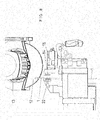
- FIGS. 6 and 7 show a suitable for carrying out the process saw blade grinding machine in a simplified representation. So missing here in the drawing all necessary for the implementation of the movement drive units, the control device, the coolant supply and so on. In particular, these machines are also equipped with a programmable controller provided so that hereby all known tooth shapes and all desired types of chamfering can be achieved.
- the running directions of the two spindles of the grinding wheel drives namely that axis of the spindle of the first grinding wheel is here designated by 16 and the axis of the spindle of the second grinding wheel by 17.
- Both grinding wheels and their drives are attached to a so-called grinding head 20 and this grinding head 20 can perform various movements.
- a first feasible movement is the horizontal movement 19, which is parallel to the plane in which the saw blade 1 is located. This saw blade 1 is held in a saw blade holder 21.
- the grinding head can also be moved in the vertical direction, as indicated by the double arrow 23. Also perpendicular to the horizontal movement 19 of the grinding head 20 is movable, as shown by the double arrow 24, which indicates the forward and backward directions. Ultimately, however, the grinding head 20 is still rotatable within a certain range in order to adjust the inclination angle of the first grinding wheel 12.
- the second grinding wheel 14 is substantially smaller in diameter and is also operated at higher speeds To achieve the sufficient peripheral speed and with this second grinding wheel 14, the machining of the cemented carbide inserts 3 takes place.
- the present machine can also carry out the usual grinding work on saw blades.
- This machine is universally applicable. So you can perform the process, as already mentioned, both on circular saw blades and band saw blades. However, shown here is only a saw blade grinding machine which is designed for circular saw blades. But as mentioned, a corresponding saw blade grinding machine can also be designed for band saw blades.
- the saw blade 1 to be processed is fixed and clamped during the execution of the method, it may additionally be useful to provide a one-sided support 22 on that side which is opposite the machining side.
- a solution may be provided in which diametrically opposed to two such grinding wheels are provided. These can be put into operation simultaneously or successively.
Landscapes
- Engineering & Computer Science (AREA)
- Mechanical Engineering (AREA)
- Finish Polishing, Edge Sharpening, And Grinding By Specific Grinding Devices (AREA)
Applications Claiming Priority (1)
| Application Number | Priority Date | Filing Date | Title |
|---|---|---|---|
| CH00916/13A CH708035A2 (de) | 2013-05-06 | 2013-05-06 | Bearbeitungsverfahren eines Sägeblattes. |
Publications (1)
| Publication Number | Publication Date |
|---|---|
| EP2801431A1 true EP2801431A1 (fr) | 2014-11-12 |
Family
ID=50513063
Family Applications (1)
| Application Number | Title | Priority Date | Filing Date |
|---|---|---|---|
| EP14165068.9A Withdrawn EP2801431A1 (fr) | 2013-05-06 | 2014-04-17 | Procédé de traitement d'une lame de scie et affûteuse à lames de scies |
Country Status (2)
| Country | Link |
|---|---|
| EP (1) | EP2801431A1 (fr) |
| CH (1) | CH708035A2 (fr) |
Cited By (3)
| Publication number | Priority date | Publication date | Assignee | Title |
|---|---|---|---|---|
| WO2017099108A1 (fr) * | 2015-12-10 | 2017-06-15 | 株式会社アマダホールディングス | Procédé de production d'une lame de scie à ruban qui prolonge la durée de vie de l'élément de cylindre, et lame de scie à ruban |
| US10710181B2 (en) | 2017-11-22 | 2020-07-14 | Swedex Ab | Saw blade for circular saw and use of such saw blade in a brush cutter |
| PL129949U1 (pl) * | 2018-12-14 | 2023-11-13 | Politechnika Lubelska | Piła z łamaczami wiórów |
Citations (7)
| Publication number | Priority date | Publication date | Assignee | Title |
|---|---|---|---|---|
| US4135421A (en) * | 1977-08-19 | 1979-01-23 | North American Products Corp. | Quiet running circular saw blade |
| DE4113854A1 (de) * | 1991-04-27 | 1992-10-29 | Kirschner Gmbh & Co Kg | Schleifmaschine zum schaerfen von saegeblaettern |
| WO1994026451A1 (fr) * | 1993-05-12 | 1994-11-24 | Mäntsälän Saha Ky | Lame de scie a creux de dents biseautes |
| EP1149652A2 (fr) | 2000-04-26 | 2001-10-31 | Iseli & Co. AG Maschinenfabrik | Procédé et dispositif pour redresser une lame de scie |
| DE20108796U1 (de) | 2001-05-18 | 2002-01-10 | RECORD Maschinenbau GmbH, 07426 Königsee | Vorrichtung zum Schärfen von Sägezahnkonturen an HSS-, Vollhartmetall- und hartmetallbestückten Kreissägeblättern |
| DE10224499A1 (de) | 2002-05-31 | 2003-12-18 | Loroch Gmbh | Verfahren zum Betrieb einer Bearbeitungsmaschine und Bearbeitungsmaschine zu seiner Ausführung |
| US8151669B2 (en) | 2009-07-16 | 2012-04-10 | Iseli & Co. Ag Maschinenfabrik | Method of and device for producing band saw blades |
-
2013
- 2013-05-06 CH CH00916/13A patent/CH708035A2/de not_active Application Discontinuation
-
2014
- 2014-04-17 EP EP14165068.9A patent/EP2801431A1/fr not_active Withdrawn
Patent Citations (7)
| Publication number | Priority date | Publication date | Assignee | Title |
|---|---|---|---|---|
| US4135421A (en) * | 1977-08-19 | 1979-01-23 | North American Products Corp. | Quiet running circular saw blade |
| DE4113854A1 (de) * | 1991-04-27 | 1992-10-29 | Kirschner Gmbh & Co Kg | Schleifmaschine zum schaerfen von saegeblaettern |
| WO1994026451A1 (fr) * | 1993-05-12 | 1994-11-24 | Mäntsälän Saha Ky | Lame de scie a creux de dents biseautes |
| EP1149652A2 (fr) | 2000-04-26 | 2001-10-31 | Iseli & Co. AG Maschinenfabrik | Procédé et dispositif pour redresser une lame de scie |
| DE20108796U1 (de) | 2001-05-18 | 2002-01-10 | RECORD Maschinenbau GmbH, 07426 Königsee | Vorrichtung zum Schärfen von Sägezahnkonturen an HSS-, Vollhartmetall- und hartmetallbestückten Kreissägeblättern |
| DE10224499A1 (de) | 2002-05-31 | 2003-12-18 | Loroch Gmbh | Verfahren zum Betrieb einer Bearbeitungsmaschine und Bearbeitungsmaschine zu seiner Ausführung |
| US8151669B2 (en) | 2009-07-16 | 2012-04-10 | Iseli & Co. Ag Maschinenfabrik | Method of and device for producing band saw blades |
Cited By (8)
| Publication number | Priority date | Publication date | Assignee | Title |
|---|---|---|---|---|
| WO2017099108A1 (fr) * | 2015-12-10 | 2017-06-15 | 株式会社アマダホールディングス | Procédé de production d'une lame de scie à ruban qui prolonge la durée de vie de l'élément de cylindre, et lame de scie à ruban |
| JP2017104940A (ja) * | 2015-12-10 | 2017-06-15 | 株式会社アマダホールディングス | 帯鋸刃の製造方法及び帯鋸刃 |
| CN108367370A (zh) * | 2015-12-10 | 2018-08-03 | 株式会社天田控股集团 | 实现了主体部件长寿命化的带锯刀的制造方法及带锯刀 |
| US20180369941A1 (en) * | 2015-12-10 | 2018-12-27 | Amada Holdings Co., Ltd. | Manufacturing method of band saw blade and band saw blade realizing longer lifetime of body member |
| EP3388178A4 (fr) * | 2015-12-10 | 2019-08-14 | Amada Holdings Co., Ltd. | Procédé de production d'une lame de scie à ruban qui prolonge la durée de vie de l'élément de cylindre, et lame de scie à ruban |
| CN108367370B (zh) * | 2015-12-10 | 2021-06-01 | 株式会社天田控股集团 | 实现了主体部件长寿命化的带锯刀的制造方法及带锯刀 |
| US10710181B2 (en) | 2017-11-22 | 2020-07-14 | Swedex Ab | Saw blade for circular saw and use of such saw blade in a brush cutter |
| PL129949U1 (pl) * | 2018-12-14 | 2023-11-13 | Politechnika Lubelska | Piła z łamaczami wiórów |
Also Published As
| Publication number | Publication date |
|---|---|
| CH708035A2 (de) | 2014-11-14 |
Similar Documents
| Publication | Publication Date | Title |
|---|---|---|
| EP2367656B2 (fr) | Machine-outil et procédé de fabrication de dentures | |
| EP1719585B1 (fr) | Machine destinée au traitement de pièces optiques, nominalement de verres de lunettes en plastique | |
| EP1987919B1 (fr) | Procédé et meuleuse destinés à profiler un outil de rectification | |
| EP2823924A2 (fr) | Machine à dresser double | |
| EP3012056A1 (fr) | Procede et dispositif de chanfreinage et d'ebavurage de pieces endentees | |
| DE102018102271A1 (de) | Zahnradschneiderbearbeitungsvorrichtung, Zahnradschneiderbearbeitungsverfahren, Werkzeugprofilsimulationsvorrichtung und Werkzeugprofilsimulationsverfahren | |
| DE1577451C3 (de) | Verfahren zum Nachschleifen eines Werkzeugstahles | |
| DE2002603A1 (de) | Verfahren und Vorrichtung zum Zuschneiden von Platten komplizierter Form aus einem Werkstoffklotz | |
| DE69412490T2 (de) | Verfahren zum schärfen von schneidklingen | |
| DE7728438U1 (de) | Stirnmesserkopf zum Verzahnen von Zahnrädern | |
| DE2545565C2 (de) | Vorrichtung zum Bearbeiten der Ein- und Austrittskanten einer Strömungsmaschinenschaufel | |
| DE19918289A1 (de) | Verfahren zum Herstellen verzahnter Werkstücke | |
| EP1967307B1 (fr) | Procédé de fabrication d'un élément de moyeu de rotor pourvu de rainures | |
| EP2801431A1 (fr) | Procédé de traitement d'une lame de scie et affûteuse à lames de scies | |
| DE3939205A1 (de) | Verfahren und vorrichtung zum schleifen von saegen | |
| DE102004022360A1 (de) | Verfahren zur Feinbearbeitung, vorzugsweise zur Feinstschlichtbearbeitung, von Werkstücken vorzugsweise von Kurbelwellen | |
| EP2477770B1 (fr) | Procédé de tournage d'une pièce entrainée en rotation | |
| EP0841116B1 (fr) | Méthode de travail de surfaces de pièces symétriques en rotation et outil employé | |
| DE2118330A1 (de) | Verfahren und Vorrichtung zum Entgraten | |
| EP2582480B1 (fr) | Utilisation d'un dispositif de tournage | |
| EP3903979A1 (fr) | Procédé d'usinage du diamètre de la tête de pièces à roue dentée et un outil combiné pour l'usinage | |
| DE2556170B2 (de) | Schleif- bzw. Poliervorrichtung für ein Zahnrad | |
| DE202014103349U1 (de) | Maschine zum Formen von Schraubenschäften | |
| DE8804806U1 (de) | Vorrichtung und Werkzeug zur Herstellung aller bekannten Gewindearten (außer Sägegewinde) in einem Arbeitsgang | |
| EP2447000B1 (fr) | Procédé de traitement d'une pièce usinée à l'aide d'une rectifieuse plane |
Legal Events
| Date | Code | Title | Description |
|---|---|---|---|
| PUAI | Public reference made under article 153(3) epc to a published international application that has entered the european phase |
Free format text: ORIGINAL CODE: 0009012 |
|
| 17P | Request for examination filed |
Effective date: 20140417 |
|
| AK | Designated contracting states |
Kind code of ref document: A1 Designated state(s): AL AT BE BG CH CY CZ DE DK EE ES FI FR GB GR HR HU IE IS IT LI LT LU LV MC MK MT NL NO PL PT RO RS SE SI SK SM TR |
|
| AX | Request for extension of the european patent |
Extension state: BA ME |
|
| STAA | Information on the status of an ep patent application or granted ep patent |
Free format text: STATUS: THE APPLICATION IS DEEMED TO BE WITHDRAWN |
|
| 18D | Application deemed to be withdrawn |
Effective date: 20150513 |