EP2801302B1 - Bereitstellungseinrichtung, Bereitstellungssystem und Verfahren zur Bereitstellung einer Liefereinheit - Google Patents
Bereitstellungseinrichtung, Bereitstellungssystem und Verfahren zur Bereitstellung einer Liefereinheit Download PDFInfo
- Publication number
- EP2801302B1 EP2801302B1 EP14075022.5A EP14075022A EP2801302B1 EP 2801302 B1 EP2801302 B1 EP 2801302B1 EP 14075022 A EP14075022 A EP 14075022A EP 2801302 B1 EP2801302 B1 EP 2801302B1
- Authority
- EP
- European Patent Office
- Prior art keywords
- delivery unit
- connection
- arranging
- loop
- connection apparatus
- Prior art date
- Legal status (The legal status is an assumption and is not a legal conclusion. Google has not performed a legal analysis and makes no representation as to the accuracy of the status listed.)
- Not-in-force
Links
- 238000012384 transportation and delivery Methods 0.000 title claims description 110
- 238000000034 method Methods 0.000 title claims description 11
- 230000000903 blocking effect Effects 0.000 claims description 15
- 230000000295 complement effect Effects 0.000 claims description 14
- 238000013475 authorization Methods 0.000 claims description 5
- 230000002349 favourable effect Effects 0.000 description 3
- 230000001960 triggered effect Effects 0.000 description 2
- 239000002023 wood Substances 0.000 description 2
- 239000004793 Polystyrene Substances 0.000 description 1
- 229910000831 Steel Inorganic materials 0.000 description 1
- 239000011111 cardboard Substances 0.000 description 1
- 239000011248 coating agent Substances 0.000 description 1
- 238000000576 coating method Methods 0.000 description 1
- 239000002131 composite material Substances 0.000 description 1
- 230000000694 effects Effects 0.000 description 1
- 239000003562 lightweight material Substances 0.000 description 1
- 239000000463 material Substances 0.000 description 1
- 239000007769 metal material Substances 0.000 description 1
- 238000004806 packaging method and process Methods 0.000 description 1
- 239000004033 plastic Substances 0.000 description 1
- 229920002223 polystyrene Polymers 0.000 description 1
- 239000010959 steel Substances 0.000 description 1
- 239000004575 stone Substances 0.000 description 1
Images


Classifications
-
- A—HUMAN NECESSITIES
- A47—FURNITURE; DOMESTIC ARTICLES OR APPLIANCES; COFFEE MILLS; SPICE MILLS; SUCTION CLEANERS IN GENERAL
- A47G—HOUSEHOLD OR TABLE EQUIPMENT
- A47G29/00—Supports, holders, or containers for household use, not provided for in groups A47G1/00-A47G27/00 or A47G33/00
- A47G29/14—Deposit receptacles for food, e.g. breakfast, milk, or large parcels; Similar receptacles for food or large parcels with appliances for preventing unauthorised removal of the deposited articles, i.e. food or large parcels
- A47G29/20—Deposit receptacles for food, e.g. breakfast, milk, or large parcels; Similar receptacles for food or large parcels with appliances for preventing unauthorised removal of the deposited articles, i.e. food or large parcels with appliances for preventing unauthorised removal of the deposited articles
Definitions
- the present invention relates to a delivery device for providing a delivery unit and to a delivery system with the delivery device according to the invention. Furthermore, the present invention relates to a method for providing a delivery unit by means of the delivery system according to the invention.
- a delivery service is often used for the delivery of food.
- the delivery order is usually triggered by telephone or other means during the delivery service.
- the food delivery is usually delivered in a suitable packaging at the person to be supplied. If this is not present at the agreed delivery address, the delivery is often with other persons, eg. B. at neighbors.
- This system is not limited solely to food deliveries, but is increasingly being used for Internet-triggered orders.
- One disadvantage of this system is, for example, that in order to receive and secure the delivery, either the person to be supplied must be present at the delivery address at the time of delivery or third parties must be involved in the delivery process.
- the present invention is therefore based on the object to provide a delivery device and a delivery system for providing a delivery unit and a method for providing a delivery unit available with which deliveries can be delivered to a delivery address in a simple, cost effective, flexible and secure way ,
- the WO 2013/049 063 A1 teaches a device for securing a theft-proof container in the form of a bag.
- the device on the bag comprises a locking mechanism.
- the securing of the bag takes place by means of a cable which is to be guided by a holder and by the closure mechanism, so that the bag is firmly connected to the holder via the cable.
- inventive provision device according to claim 1 and by the inventive provisioning system according to claim 9 and the inventive method for providing a delivery unit according to claim 10.
- Advantageous embodiments of the providing device are specified in the subclaims 2 to 8.
- An advantageous embodiment of the method for providing a delivery unit is specified in claim 11.
- the provision device serves to provide a delivery unit, wherein the provision device comprises a connection device for the mechanical securing of the delivery unit and has a first form element, which is positively and / or non-positively mechanically connected and / or connected to a substantially position-secured fixing element.
- the connection device can be brought or brought into operative connection with the fixing element in such a way that the connection device and the fixing element together form a blocking unit whose opening requires an access authorization proof.
- the supply device comprises a delivery unit which is mechanically connected or connectable to the connection device, wherein the connection device has a second form element for realizing a non-positive and / or positive connection to the delivery unit to be secured.
- the second form element is designed as an eyelet.
- the supply device further comprises a connecting element for realizing a mechanical connection between the delivery unit and the connection device, wherein the connecting element is a rope with at least one loop arranged at one end.
- the loop is pulled through the eyelet and the rope is pulled through this loop.
- the proof of access can be provided by a mechanical or electronic key.
- the delivery unit may in particular be a container which is suitable for receiving food.
- the fixing element may be, for example, a house or apartment door, a mailbox or its door or even an element on a garden gate or garden fence. In the embodiment as a door, the fixing element is positioned to the effect that the door is indeed pivotable, but is secured against unauthorized removal.
- the loop of the rope should be so large that the connection device can be inserted through this loop.
- the second form element should preferably be an eyelet, which z. B. can run parallel to a central part of a designed as a U-shaped connection device.
- the connection device can also have the second form element, but this is not necessarily provided.
- connection between the connecting device and the connecting element can be produced manually in a simple manner, even if the connecting device is fixed to the fixing element, namely by the loop is inserted through the eyelet and the rope is then threaded through the loop. However, this requires a free end of the rope.
- the eyelet is in the broadest sense an opening in the connection device and is not necessarily limited to a ring shape. This makes it possible to realize a simple and inexpensive connection between the connection device and the connection element.
- the advantage of the provisioning device according to the invention is, in particular, that only an authorized person can open the blocking unit with proof of access authorization and thus move the connection device and release the delivery unit from the fixing element in order to completely take possession of the delivery unit.
- connection device has a first form element, which can be arranged or arranged positively and / or non-positively on a door leaf such that the connection device is taken perpendicular to the door leaf plane when the door is closed, at least the translatory degree of freedom.
- the fixing device is the door, which forms the locking unit together with the connection device. Only the one who has a key to the door is able to release the delivery unit from the locking unit, namely by opening the door.
- the supply device thus serves to provide the delivery unit in the vicinity of a door, in particular an apartment door, for example, for delivery to food, if the person to be supplied does not stay at the delivery address.
- connection device prevents it from being pulled off the door leaf when the door is closed. This ensures a backup of the connection device in its position against unauthorized removal. Only an authorized person, who has a key to the door and can open it, can therefore also separate the connection device from the door. Thus, only this person can get into possession of the secured and connected to the connection device delivery unit.
- Another favorable embodiment of the connection device is, if this is blocked in its rotational degree of freedom about the door leaf edge against which the connection device, as well as blocked in the rotational degree of freedom about the axis perpendicular to this door leaf edge in the plane of the door leaf.
- connection device should be taken two translational degrees of freedom and all rotational degrees of freedom, wherein a translation of the connection device along an edge of the door leaf in the door leaf level is permitted.
- the connection device when applied to the door leaf connection device and door closed when this is in the door frame and is locked or can be locked, the connection device preferably can not be moved out of the Terblattebene by positive engagement, so they are not taken away by any unauthorized person can be.
- the terminal device in the door leaf plane can be removed from the door and moved separately from the door, so that a delivery unit connected to the terminal device is also movable.
- the first form element of the connection device is adapted substantially complementary to an edge region of the door leaf.
- This embodiment is related to a typical door having a substantially planar door leaf, i. h., The edge region of the door leaf is designed rectangular in cross-section, so that the first mold element of the connection device also forms a rectangular receiving area.
- the first form element of the connection device may substantially have the cross section of an angle profile, preferably a U-profile, wherein at least one of the legs of the angle profile serves as a blocking element for blocking the connection device in its movement perpendicular to the door leaf level.
- the blockade element should have a length which is greater than an average door gap, i. h., A length which is greater than the maximum height of a distance between the lower edge of a door leaf and the underlying ground or underlying threshold. In usual embodiments, a length of the blocking element between 10mm and 50 mm should be sufficient.
- the angle between the blockade element and a portion of the first mold element, which extends in the door leaf level and forms a central part of a U-profile should have a maximum of 120 °, but the actual design depends on the width of the door gap and the door leaf thickness to prevent the connection device can be pulled out of the door gap and / or unscrewed.
- the portion of the first mold element which extends in the door leaf level and is configured as a central part in a U-profile should have at least a length which, measured perpendicular to the door leaf plane, is greater than the thickness of the door leaf.
- the first form element of the connection device can have, at least in sections, essentially the cross-section of a U-profile, one of the legs of the U-profile being designed as a blocking element.
- the connection device should, at least in the region extending in the door leaf plane, have a width which is greater than a typical door gap of dwelling doors. That is, the width is preferably greater than 5 mm should, wherein the width dimension in the direction of the longitudinal course of the door gap is to measure. Regardless of the width of a door gap, the width of the connection device in its embodiment with a U-profile-shaped section will thus be greater than the thickness of the middle section of the U-profile.
- connection device has a first form element which can be arranged and arranged positively and / or non-positively in a slot of a mailbox in such a way that at least the translational degree of freedom is taken perpendicular to the plane when the mailbox is closed. in which the mailbox slot extends.
- This blocking of the translatory degree of freedom can, for. B. be achieved in that the connection device has a corresponding length of a section located behind the letterbox slot.
- the fixing device is the mailbox door, in which the slot is arranged, and which forms the locking unit together with the connection device. Only the person who has a key to the mailbox is able to release the delivery unit from the mailbox, namely by opening the mailbox door and exposing the connection device.
- This supply device according to the invention thus serves to provide the delivery unit in the vicinity of a mailbox.
- connection device is the rotation around the letter box slot edge against which the connection device is applied, taken, as well as the rotation is blocked by a perpendicular to this letter box slot edge extending in the plane of the door of the mailbox axis.
- connection device is also here taken with two translational degrees of freedom and all rotational degrees of freedom, wherein only one translation of the connection device along an edge of the slot of the mailbox in the plane of the door of the mailbox is permitted. It is assumed that the door of the mailbox is located in a frame of the mailbox and locked there or can be locked. By opening the mailbox door, the connection direction can be separated, so that it can be removed from the mailbox together with the delivery unit connected thereto.
- connection device can be locked and unlocked and has a first form element which can be connected or connected positively and / or non-positively to an element of a garden gate or garden fence in such a way that the connection device is in the locked state on the garden gate or gate is fixed on the garden fence. This means that the connection device can be opened and closed. Because the connection device can not be removed from the garden gate or garden fence in the locked state, the delivery unit mechanically connected to the connection device can not be removed.
- the fixing device is the garden gate or garden fence, which forms the blocking unit together with the connection device.
- connection device Only the one who has a key to the connection device is able to release the connection device and thus also the delivery unit connected thereto from the garden gate or garden fence, namely by unlocking or unlocking the connection device.
- This connection device may in particular be a padlock or a bicycle lock or the like.
- This supply device thus serves to provide the delivery unit in the vicinity of a garden gate or garden fence, z. b. for the delivery of food, if the person to be served is not in the garden or the house belonging to it. Only an authorized person who has a key to the connection device and can open it, is able to separate the connection device of garden gate or garden fence. Thus, only this person can get into the possession of the delivery unit connected to the connection device.
- the connecting element is a rope with loops arranged at both ends, wherein a first end of the rope, with the loop arranged thereon, through the eye of the connection device and the second loop by means of a closure device on a molded element of the delivery unit force and / or is positively secured against removal.
- the closure device is a padlock, wherein the second loop of the rope through a receiving lug of the delivery unit pulled through and the padlock is hung in the second loop and closed, the maximum clear width of the receiving lug of the delivery unit is less than the minimum spatial extent of the padlock.
- a supplier can attach the rope with the first loop to the attachment device and pull the second loop through the eyelet of the delivery unit and then secure the rope in this position by hanging and closing the padlock in the second loop.
- the rope or its second loop can no longer be pulled out of the receiving lug of the delivery unit, so that the delivery unit is mechanically connected via the cable to the connection device. Only the one who can solve the connection device, z. Example, by opening a door, in the gap, the connection device is arranged, is able to lift the mechanical connection between the delivery unit and the door and take the delivery unit in possession.
- the delivery unit has a lid and a container, wherein the receiving lug is arranged on one of the elements lid and container and on the respective other element a complementary part is arranged, which is substantially fixed in position when an object, such. B. the rope extends through the receiving lug.
- the complementary part is pivotable about a hinge axis and has a slot through which the receiving lug can extend, so that the receiving lug and the complementary part form a conventional box closure. After being exposed, the supplied person can thread them through the first loop of the rope, so that the first loop and the rope can be pulled out of the connection device or out of its first form element.
- the rope can also be pulled out of the receiving lug of the delivery unit, so that the complementary part can be pivoted away from the receiving lug.
- the supplied person now also has the option of releasing the lid from the container and thus accessing the contents of the delivery unit.
- the supplier can thus connect the delivery unit to the person to be delivered, whereby the supplied person does not have a key to open the delivery Delivery unit needed to take possession and open.
- the connection device can again be connected to the fixing element just as described, without the supplied person needing a key for this purpose.
- the rope is pulled through the receiving lug of the delivery unit, where it is blocked at one end by the closed padlock.
- the first loop of the rope is pulled through the eyelet of the connection device, after which the connection device itself is threaded through this loop.
- the thus fastened to the rope connection device can be positioned in the door gap or in a letterbox gap again and fixed there by closing the respective door. That is, the inventive provision device is particularly useful for deliveries when the person to be supplied is not present at the delivery address, and the return of the delivery unit can be done easily if the person to be supplied is not present at the time of withdrawal of the delivery unit.
- a further aspect of the present invention is a provisioning system which comprises a provisioning device according to the invention and a fixing element which is brought into operative connection with the connection device of the delivery device in such a way that the connection device and the fixing element together form a blocking unit whose opening requires an access authorization certificate.
- the fixation device may, for. B. a door, such. B. an apartment door, a mailbox door with a slot or a garden gate or a garden fence.
- connection device should preferably have a coating or be made of a material or together with wood, stone and / or linoleum forms a low coefficient of friction, such as. B. a felt layer.
- the delivery unit may be made of a suitable and preferably lightweight material such. As plastic, polystyrene, wood or cardboard, but embodiments of steel and sheet metal or composite materials should not be excluded.
- connection device is permanently connected to the connecting element, to which a supplier can connect the delivery unit in the manner described.
- a supplier can connect the delivery unit in the manner described.
- the connecting element preferably in the form of a cable, is firmly connected to the lock of the delivery unit or to this.
- the delivery unit itself is freely available when the door or the mailbox or the connection device is opened.
- a method for providing a delivery unit in which a provision system according to the invention is used to mechanically connect a delivery unit by means of the connection device to the fixing element, wherein a mechanical connection between the connection device and the delivery unit is produced.
- this method is carried out in an embodiment of the provision system in which the connection device has an eyelet as a second mold element and the supply device further comprises a connection element between the connection device and the delivery unit, which is a cable with loops arranged at both ends.
- the delivery unit should have a lid and a container, wherein on one of the elements lid and container a receiving lug is arranged and on the respective other element a complementary part is arranged, which is substantially fixable in its position when an object extends through the receiving lug ,
- a first loop of the rope is inserted through the eyelet of the connection device and the connecting element or rope is then threaded through the first loop and the second loop of the rope is pulled through the receiving lug of the delivery unit and then a Padlock is hung in the second loop and locked.
- the supplied person in the case of the arrangement of the terminal device in a door gap or a letterbox slot open the door or mailbox, remove the connection device from the gap or slot area, thread the connection device through the first loop and then the rope from the connection device pull out. Then the rope can also pull out of the receiving lug of the delivery unit, so that it is completely movable and thus can be carried and opened in an apartment.
- connection device In the case of the use of a lockable and unlockable connection device and its arrangement on a garden gate or garden fence, the connection device must first be unlocked, z. B. by using a key. A connected to the connection device connecting element and form of a rope which z. B. was connected by the connection device, can now be separated from the garden gate or garden fence and also pull out of the receiving lug of the delivery unit, so that this and the content is available.
- the connection device 10 is here blocked in its perpendicular to the door leaf plane translational degree of freedom 60, as with respect to the Figures 2 and 3 will be explained.
- connection device 10 By blocking the translational degree of freedom 60, the connection device 10 can not be removed from the fixing element 40, if this, designed as a door, is not opened.
- a first loop 71 which is arranged at one end of a connecting element 70 designed as a cable, is threaded through, and the connecting element 70 is threaded through this first loop 71.
- a very simple mechanical connection between the connecting element 70 and the connecting device 10 is realized, which can easily be released manually when the connecting device 10 is exposed by opening the fixing element 40 provided as a door.
- the liberated connection device 10 is threaded through the first loop 71, so that the first loop 71 can also be pulled out of the loop-like second mold element 12 again.
- the one end of the rope-like connecting element 70 is exposed.
- the connecting element 70 has, at its end opposite the connecting device 10, a second loop 72, in which a closure device 80, here a form of padlock, is suspended and closed.
- the connecting element 70 leads through a receiving lug 33 of the delivery unit 30, this receiving lug 33 being arranged on the container 32 of the delivery unit 30.
- the delivery unit 30 further comprises a cover 31 covering or closing the container 32, on which a pivotable complementary part 34 is arranged.
- the complementary part 34 is pivoted on the receiving lug 33, that the receiving lug 33 and the complementary part 34 together form a box closure.
- the rope-like connecting element 70 passes through the receiving eye 33, so that the complementary part 34 can not be pivoted and thus the lid 31 is fixed on the container 32. Characterized in that in the second loop 72, the connecting element 70, the closure device 80 is mounted, the connecting element 70 can not be pulled out of the receiving lug 33, so that the delivery unit 33 is closed and, in the Fig. 1 illustrated embodiment, when the fixing element 40 is closed inextricably connected to this fixing element 40 and with the connecting device 10 connected thereto.
- connection element 70 can also be pulled out of the receiving lug 33, so that the delivery unit 30 is freely movable and the complementary part 34 of the receptacle 33rd can be swung away and the lid 31 from the container 32 is removable, so that the supplied person can take the contents of the delivery unit 30 in possession.
- connection device 10 configured with a first mold element 11, which can form a positive connection with the door leaf of the fixing element 40.
- This first shaped element is preferably an angle profile, in particular an illustrated U-profile 20, whose leg remote from the second shaped element 12 is designed as a blocking element 21.
- connection device 10 in such a door gap 41 arrange that the U-profile 20 surrounds the fixing element 40 at its edge region, wherein the blocking element 21, the movement of the connection device 10 in a direction of the translational degree of freedom 60, namely in the direction of the second mold element 12th prevents so that the terminal device 10 can be removed only from the fixing member 40 when this fixing member 40 is moved to a position in which the terminal device 10 is removable.
- this position is the position of the door outside the door frame, in which the connection device 10 in a simple manner under the open door pushed or moved away from there.
Landscapes
- Engineering & Computer Science (AREA)
- Food Science & Technology (AREA)
- Supports Or Holders For Household Use (AREA)
Description
- Die vorliegende Erfindung betrifft eine Bereitstellungseinrichtung zur Bereitstellung einer Liefereinheit sowie ein Bereitstellungssystem mit der erfindungsgemäßen Bereitstellungseinrichtung. Des Weiteren betrifft die vorliegende Erfindung ein Verfahren zur Bereitstellung einer Liefereinheit mittels des erfindungsgemäßen Bereitstellungssystems.
- Insbesondere in Dienstleistungsgesellschaften sowie zur Verpflegung älterer Personen wird häufig ein Lieferservice zur Anlieferung von Lebensmitteln genutzt. Der Lieferauftrag wird dabei für gewöhnlich telefonisch oder auf anderem Wege beim Lieferservice ausgelöst. Zu einem vereinbarten Zeitpunkt wird dann die Lebensmittellieferung zumeist in einer geeigneten Verpackung bei der zu beliefernden Person abgegeben. Falls diese nicht an der vereinbarten Lieferadresse zugegen ist, wird die Lieferung häufig bei anderen Personen, z. B. bei Nachbarn, abgegeben.
- Dieses System ist dabei nicht alleine auf Lebensmittellieferungen eingeschränkt, sondern wird zunehmend auch für im Internet ausgelöste Bestellungen verwendet.
- Nachteilig an diesem System ist unter anderem, dass zum Erhalt und zur Sicherung der Lieferung entweder die zu beliefernde Person zum Zeitpunkt der Lieferung bei der Lieferadresse anwesend sein muss oder aber Dritte in den Lieferprozess involviert werden müssen.
- Der vorliegenden Erfindung liegt daher die Aufgabe zu Grunde, eine Bereitstellungseinrichtung sowie ein Bereitstellungssystem zur Bereitstellung einer Liefereinheit sowie ein Verfahren zur Bereitstellung einer Liefereinheit zur Verfügung zu stellen, mit denen in einfacher, kostengünstiger, flexibler und sicherer Art und Weise Lieferungen an einer Lieferadresse ablieferbar sind.
- Die
WO 2013/049 063 A1 lehrt eine Einrichtung zur Sicherung eines diebstahlsicheren Behälters in Form eines Beutels. Zu diesem Zweck umfasst die Einrichtung am Beutel einen Verschlussmechanismus. Die Sicherung des Beutels erfolgt mittels eines Seils, welches durch eine Halterung sowie durch den Verschlussmechanismus zu führen ist, so dass der Beutel über das Seil fest mit der Halterung verbunden ist. - Diese Aufgabe wird durch die erfindungsgemäße Bereitstellungseinrichtung nach Anspruch 1 sowie durch das erfindungsgemäße Bereitstellungssystem nach Anspruch 9 und das erfindungsgemäße Verfahren zur Bereitstellung einer Liefereinheit nach Anspruch 10 gelöst. Vorteilhafte Ausgestaltungen der Bereitstellungseinrichtung sind in den Unteransprüchen 2 bis 8 angegeben. Eine vorteilhafte Ausgestaltung des Verfahrens zur Bereitstellung einer Liefereinheit ist im Anspruch 11 angegeben.
- Die erfindungsgemäße Bereitstellungseinrichtung dient zur Bereitstellung einer Liefereinheit, wobei die Bereitstellungseinrichtung eine Anschlusseinrichtung zur mechanischen Sicherung der Liefereinheit umfasst und ein erstes Formelement aufweist, welches form- und/oder kraftschlüssig mit einem im Wesentlichen positionsgesicherten Fixierungselement mechanisch verbindbar und/oder verbunden ist. Die Anschlusseinrichtung ist mit dem Fixierungselement derart in Wirkverbindung bringbar oder gebracht, dass die Anschlusseinrichtung und das Fixierungselement zusammen eine Sperreinheit ausbilden, deren Öffnung einen Zugangsberechtigungsnachweis erfordert. Weiterhin umfasst die erfindungsgemäße Bereitstellungseinrichtung eine Liefereinheit, die mit der Anschlusseinrichtung mechanisch verbunden oder verbindbar ist, wobei die Anschlusseinrichtung ein zweites Formelement aufweist zur Realisierung einer kraft- und/oder formschlüssigen Verbindung zur zu sichernden Liefereinheit.
- Das zweite Formelement ist dabei als eine Öse ausgestaltet.
- Die Bereitstellungseinrichtung weist weiterhin ein Verbindungselement zur Realisierung einer mechanischen Verbindung zwischen der Liefereinheit und der Anschlusseinrichtung auf, wobei
das Verbindungselement ein Seil ist mit wenigstens einer an einem Ende angeordneten Schlaufe. - Die Schlaufe ist durch die Öse hindurch gezogen und das Seil ist durch diese Schlaufe hindurch gezogen.
- Der Zugangsberechtigungsnachweis kann dabei durch einen mechanischen oder elektronischen Schlüssel erbracht sein. Die Liefereinheit kann insbesondere ein Behälter sein, welcher zur Aufnahme von Lebensmitteln geeignet ist. Das Fixierungselement kann zum Beispiel eine Haus- oder Wohnungstür, ein Briefkasten bzw. dessen Tür oder auch ein Element an einem Gartentor bzw. Gartenzaun sein. In der Ausführung als Tür ist das Fixierungselement dahingehend positionsgesichert, dass die Tür zwar schwenkbar ist, jedoch gegen unbefugte Wegnahme gesichert ist.
- Es bietet sich an, das Seil als Drahtseil auszuführen. Die Schlaufe des Seils sollte so groß sein, dass die Anschlusseinrichtung durch diese Schlaufe hindurch steckbar ist.
- Im Fall der beabsichtigten Anordnung der Anschlusseinrichtung in einem Türspalt bzw. in einem Briefkastenschlitz sollte das zweite Formelement vorzugsweise eine Öse sein, welche z. B. zu einem Mittelteil einer als U-Profil ausgestalteten Anschlusseinrichtung parallel verlaufen kann.
Im Fall der beabsichtigten Anordnung der Anschlusseinrichtung als verschließbare Einheit an einem Gartentor bzw. Gartenzaun kann die Anschlusseinrichtung ebenfalls das zweite Formelement aufweisen, wobei dieses jedoch nicht zwingend vorgesehen ist. - Die Verbindung zwischen der Anschlusseinrichtung und dem Verbindungselement lässt sich in einfacher Weise manuell herstellen, auch wenn die Anschlusseinrichtung am Fixierungselement fixiert ist, nämlich indem die Schlaufe durch die Öse gesteckt wird und das Seil danach durch die Schlaufe gefädelt wird. Dies setzt jedoch ein freies Ende des Seils voraus. Die Öse ist dabei im weitesten Sinne eine Öffnung in der Anschlusseinrichtung und ist nicht zwingend auf eine Ringform eingeschränkt. Dadurch lässt sich eine einfache und kostengünstige Verbindung zwischen der Anschlusseinrichtung und dem Verbindungselement realisieren.
- Der Vorteil der erfindungsgemäßen Bereitstellungseinrichtung liegt insbesondere darin, dass nur eine befugte Person unter Nachweis der Zugangsberechtigung die Sperreinheit öffnen kann und somit die Anschlusseinrichtung bewegen und die Liefereinheit von dem Fixierungselement lösen kann, um die Liefereinheit vollständig in Besitz zu nehmen.
- In vorteilhafter Ausgestaltung weist die Anschlusseinrichtung ein erstes Formelement auf, welches form- und/oder kraftschlüssig derart an einem Türblatt anordbar oder angeordnet ist, dass der Anschlusseinrichtung bei geschlossener Tür wenigstens der translatorische Freiheitsgrad senkrecht zur Türblattebene genommen ist. In dieser Ausgestaltung ist somit die Fixierungseinrichtung die Tür, die zusammen mit der Anschlusseinrichtung die Sperreinheit ausbildet. Nur derjenige, der einen Schlüssel zu der Tür hat, ist in der Lage, die Liefereinheit von der Sperreinheit zu lösen, nämlich durch Öffnung der Tür. Die Bereitstellungseinrichtung dient somit der Bereitstellung der Liefereinheit in der Nähe einer Türe, insbesondere einer Wohnungstüre, zum Beispiel zur Belieferung mit Lebensmitteln, wenn sich die zu beliefernde Person nicht an der Lieferadresse aufhält. Durch das erste Formelement der Anschlusseinrichtung wird verhindert, dass Diese vom Türblatt abgezogen werden kann, wenn die Tür geschlossen ist. Dadurch erfolgt eine Sicherung der Anschlusseinrichtung in ihrer Position gegen unbefugte Wegnahme. Nur eine berechtigte Person, die einen Schlüssel zu der Tür hat und Diese öffnen kann, kann somit auch die Anschlusseinrichtung von der Tür separieren. Somit kann auch nur diese Person in Besitz der gesicherten und an die Anschlusseinrichtung angeschlossenen Liefereinheit gelangen. Eine weitere günstige Ausgestaltung der Anschlusseinrichtung ist, wenn diese auch in ihrem rotatorischen Freiheitsgrad um die Türblattkante, an der die Anschlusseinrichtung anliegt, blockiert ist, sowie in dem rotatorischen Freiheitsgrad um die senkrecht zu dieser Türblattkante in der Ebene des Türblattes verlaufende Achse blockiert ist. Vorzugsweise sollten der Anschlusseinrichtung zwei translatorische Freiheitsgrade und alle rotatorischen Freiheitsgrade genommen sein, wobei eine Translation der Anschlusseinrichtung entlang einer Kante des Türblattes in der Türblattebene zulässig ist. Das heißt, dass bei am Türblatt angelegter Anschlusseinrichtung und geschlossener Türe, wenn sich Diese im Türrahmen befindet und verriegelt ist oder verriegelt werden kann, die Anschlusseinrichtung vorzugsweise mittels Formschluss nicht aus der Türblattebene heraus bewegt werden kann, so dass sie auch von keiner unbefugten Person weggenommen werden kann. Wird jedoch die Tür geöffnet, lässt sich die Anschlusseinrichtung in der Türblattebene von der Tür entfernen und separat von der Tür bewegen, so dass eine an der Anschlusseinrichtung angeschlossene Liefereinheit ebenfalls bewegbar ist.
- In einer bevorzugten Ausgestaltung ist vorgesehen, dass das erste Formelement der Anschlusseinrichtung im Wesentlichen einem Kantenbereich des Türblattes komplementär angepasst ist. Diese Ausgestaltung ist auf eine typische Tür mit einem im Wesentlichen ebenen Türblatt bezogen, d. h., der Kantenbereich des Türblattes ist im Querschnitt rechteckig ausgestaltet, so dass das erste Formelement der Anschlusseinrichtung ebenfalls einen rechteckigen Aufnahmebereich ausbildet. Dabei kann das erste Formelement der Anschlusseinrichtung im Wesentlichen den Querschnitt eines Winkelprofils, bevorzugt ein U-Profil aufweisen, wobei wenigstens einer der Schenkel des Winkelprofils als Blockadeelement zwecks Blockade der Anschlusseinrichtung in ihrer Bewegung senkrecht zur Türblattebene dient.
- Das Blockadeelement sollte eine Länge haben, die größer ist als ein durchschnittlicher Türspalt, d. h., eine Länge, die größer ist als die maximale Höhe eines Abstandes zwischen der Unterkante eines Türblattes und dem darunter befindlichen Boden bzw. der darunter befindlichen Schwelle. In üblichen Ausgestaltungen sollte eine Länge des Blockadeelements zwischen 10mm und 50 mm ausreichend sein.
- Der Winkel zwischen dem Blockadeelement und einem Abschnitt des ersten Formelementes, welches in der Türblattebene verläuft und ein Mittelteil eines U-Profils ausbildet, sollte maximal 120° aufweisen, wobei jedoch die konkrete Ausgestaltung abhängig ist von der Breite des Türspaltes und der Türblattdicke, um zu verhindern, dass die Anschlusseinrichtung aus dem Türspalt herausgezogen und/oder herausgedreht werden kann. Der Abschnitt des ersten Formelementes, der in der Türblattebene verläuft und bei einem U-Profil als Mittelteil ausgestaltet ist, sollte wenigstens eine Länge haben, die, gemessen senkrecht zur Türblattebene, größer ist als die Dicke des Türblattes.
- Wie bereits erwähnt, kann das erste Formelement der Anschlusseinrichtung zumindest abschnittsweise im Wesentlichen den Querschnitt eines U-Profils aufweisen, wobei einer der Schenkel des U-Profils als Blockadeelement ausgeführt ist. Damit eine Rotation um eine senkrecht zur Türblattebene verlaufende Achse verhindert wird, sollte die Anschlusseinrichtung zumindest in dem in Türblattebene verlaufenden Bereich eine Breite aufweisen, die größer ist als ein typischer Türspalt von Wohnungstüren. Das heißt, dass die Breite vorzugsweise größer als 5 mm sein sollte, wobei das Breitenmaß in Richtung des Längsverlaufes des Türspaltes zu messen ist. Unabhängig von der Breite eines Türspaltes wird somit die Breite der Anschlusseinrichtung in ihrer Ausführungsform mit einem U-profilförmigen Abschnitt größer sein als die Dicke des Mittelteils des U-Profils.
- In einer anderen Ausführungsvariante ist vorgesehen, dass die Anschlusseinrichtung ein erstes Formelement aufweist, welches form- und/oder kraftschlüssig derart in einem Schlitz eines Briefkastens anordbar oder angeordnet ist, dass der Anschlusseinrichtung bei geschlossenem Briefkasten wenigstens der translatorische Freiheitsgrad senkrecht zu der Ebene genommen ist, in der sich der Briefkastenschlitz erstreckt. Diese Blockierung des translatorischen Freiheitsgrades kann z. B. dadurch erreicht sein, dass die Anschlusseinrichtung eine entsprechende Länge eines hinter dem Briefkastenschlitz befindlichen Abschnitts aufweist. In dieser Ausgestaltung ist die Fixierungseinrichtung die Briefkastentür, in der der Schlitz angeordnet ist, und die zusammen mit der Anschlusseinrichtung die Sperreinheit ausbildet. Nur diejenige Person, die einen Schlüssel zum Briefkasten hat, ist in der Lage, die Liefereinheit vom Briefkasten zu lösen, nämlich durch Öffnen der Briefkastentüre und Freilegung der Anschlusseinrichtung. Diese erfindungsgemäße Bereitstellungseinrichtung dient somit der Bereitstellung der Liefereinheit in der Nähe eines Briefkastens.
- Auch in dieser Ausgestaltungsvariante ist vorgesehen, dass der Anschlusseinrichtung die Rotation um die Briefkastenschlitzkante, an der die Anschlusseinrichtung anliegt, genommen ist, sowie auch die Rotation um eine senkrecht zu dieser Briefkastenschlitzkante in der Ebene der Tür des Briefkastens verlaufende Achse blockiert ist. In günstigster Ausgestaltung sind auch hier der Anschlusseinrichtung zwei translatorische Freiheitsgrade und alle rotatorischen Freiheitsgrade genommen, wobei lediglich eine Translation der Anschlusseinrichtung entlang einer Kante des Schlitzes des Briefkastens in der Ebene der Tür des Briefkastens zulässig ist. Es wird dabei davon ausgegangen, dass die Tür des Briefkastens sich in einem Rahmen des Briefkastens befindet und dort verriegelt ist oder verriegelt werden kann. Durch Öffnung der Briefkastentür lässt sich die Anschlussrichtung separieren, so dass sie zusammen mit der daran angeschlossenen Liefereinheit vom Briefkasten entfernbar ist.
- In einer dritten Ausgestaltungsvariante ist vorgesehen, dass die Anschlusseinrichtung ver- und entriegelbar ist und ein erstens Formelement aufweist, welches form- und/oder kraftschlüssig derart an einem Element eines Gartentores oder Gartenzaunes anschließbar oder angeschlossen ist, dass die Anschlusseinrichtung im verriegelten Zustand am Gartentor bzw. am Gartenzaun fixiert ist. Das heißt, dass die Anschlusseinrichtung zu- und aufschließbar ist. Dadurch, dass die Anschlusseinrichtung im verriegelten Zustand nicht vom Gartentor bzw. Gartenzaun entfernbar ist, kann auch die mit der Anschlusseinrichtung mechanisch verbundene Liefereinheit nicht entfernt werden. In dieser Ausführungsvariante ist die Fixierungseinrichtung das Gartentor bzw. der Gartenzaun, das bzw. der zusammen mit der Anschlusseinrichtung die Sperreinheit ausbildet. Nur derjenige, der einen Schlüssel zu der Anschlusseinrichtung hat, ist in der Lage, die Anschlusseinrichtung und somit auch die daran angeschlossene Liefereinheit vom Gartentor bzw. Gartenzaun zu lösen, nämlich durch Entriegeln bzw. Aufschließen der Anschlusseinrichtung. Diese Anschlusseinrichtung kann insbesondere ein Vorhängeschloss oder ein Fahrradschloss oder ähnliches sein.
- Diese erfindungsgemäße Bereitstellungseinrichtung dient somit der Bereitstellung der Liefereinheit in der Nähe eines Gartentores bzw. Gartenzaunes, z. b. zur Auslieferung von Lebensmitteln, wenn sich die zu beliefernde Person nicht im Garten bzw. dem dazugehörigen Haus aufhält. Nur eine berechtigte Person, die einen Schlüssel zu der Anschlusseinrichtung hat und diese öffnen kann, ist in der Lage, die Anschlusseinrichtung von Gartentor bzw. Gartenzaun zu separieren. Somit kann auch nur diese Person in den Besitz der an die Anschlusseinrichtung angeschlossenen Liefereinheit gelangen.
- In günstiger Ausgestaltung der erfindungsgemäßen Bereitstellungseinrichtung ist das Verbindungselement ein Seil mit beidendig angeordneten Schlaufen, wobei ein erstes Seilende, mit der daran angeordneten Schlaufe, durch die Öse der Anschlusseinrichtung führt und die zweite Schlaufe mittels einer Verschlusseinrichtung an einem Formelement der Liefereinheit kraft- und/oder formschlüssig gegen Wegnahme gesichert ist.
- Es bietet sich hierbei an, dass die Verschlusseinrichtung ein Vorhängeschloss ist, wobei die zweite Schlaufe des Seiles durch eine Aufnahmeöse der Liefereinheit hindurch gezogen ist und das Vorhängeschloss in die zweite Schlaufe eingehängt und verschlossen ist, wobei die maximale lichte Weite der Aufnahmeöse der Liefereinheit geringer ist als die minimale räumliche Erstreckung des Vorhängeschlosses. Derart kann ein Lieferant das Seil mit der ersten Schlaufe an der Anschlusseinrichtung befestigen und die zweite Schlaufe durch die Öse der Liefereinheit ziehen und dann das Seil in dieser Position sichern, in dem er das Vorhängeschloss in die zweite Schlaufe einhängt und verschließt. Das Seil bzw. dessen zweite Schlaufe kann nicht mehr aus der Aufnahmeöse der Liefereinheit herausgezogen werden, so dass die Liefereinheit über das Seil mit der Anschlusseinrichtung mechanisch verbunden ist. Nur derjenige, der die Anschlusseinrichtung lösen kann, z. B. durch Öffnen einer Tür, in deren Spalt die Anschlusseinrichtung angeordnet ist, ist in der Lage, die mechanische Verbindung zwischen der Liefereinheit und der Tür aufzuheben und die Liefereinheit in Besitz zu nehmen.
- Weiterhin ist es in bevorzugter Ausgestaltung der Erfindung vorgesehen, dass die Liefereinheit einen Deckel und einen Behälter aufweist, wobei an einem der Elemente Deckel und Behälter die Aufnahmeöse angeordnet ist und am jeweils anderen Element ein Komplementärteil angeordnet ist, welches in seiner Position im Wesentlichen fixierbar ist, wenn sich ein Gegenstand, wie z. B. das Seil, durch die Aufnahmeöse erstreckt. Vorzugsweise ist das Komplementärteil um eine Scharnierachse schwenkbar und weist einen Schlitz auf, durch welchen sich die Aufnahmeöse erstrecken kann, so dass die Aufnahmeöse und das Komplementärteil einen gewöhnlichen Kistenverschluss ausbilden. Die belieferte Person kann nach Freilegung der Anschlusseinrichtung diese durch die erste Schlaufe des Seils hindurch fädeln, so dass die erste Schlaufe und das Seil aus der Anschlusseinrichtung bzw. aus deren erstem Formelement herausziehbar ist. Sodann kann das Seil auch aus der Aufnahmeöse der Liefereinheit herausgezogen werden, so dass das Komplementärteil von der Aufnahmeöse weggeschwenkt werden kann. Neben der Verfügbarkeit über die Liefereinheit hat nun die belieferte Person gleichzeitig auch die Möglichkeit, den Deckel vom Behälter zu lösen und somit an den Inhalt der Liefereinheit zu gelangen.
- Der Lieferant kann somit die Liefereinheit bei der zu beliefernden Person anschließen, wobei die belieferte Person keinen Schlüssel zur Öffnung der Liefereinheit benötigt, um diese in Besitz zu nehmen und zu öffnen. Zur Bereitstellung der Liefereinheit zwecks Abholung kann wieder genauso wie beschrieben die Anschlusseinrichtung mit dem Fixierungselement verbunden werden, ohne dass die belieferte Person dafür einen Schlüssel benötigt. Zu diesem Zweck wird das Seil durch die Aufnahmeöse der Liefereinheit gezogen, wobei es einendig durch das geschlossene Vorhängeschloss blockiert wird. Die erste Schlaufe des Seils wird durch die Öse der Anschlusseinrichtung gezogen, danach wird die Anschlusseinrichtung selbst durch diese Schlaufe gefädelt. Die somit am Seil befestigte Anschlusseinrichtung kann wieder im Türspalt oder in einem Briefkasten-Spalt positioniert werden und mittels Schließung der jeweiligen Tür dort fixiert werden. Das heißt, das die erfindungsgemäße Bereitstellungseinrichtung insbesondere für Lieferungen verwendbar ist, wenn die zu beliefernde Person nicht an der Lieferadresse anwesend ist, wobei auch die Rücknahme der Liefereinheit problemlos erfolgen kann, wenn die zu beliefernde Person zum Zeitpunkt der Rücknahme der Liefereinheit nicht zugegen ist.
- Ein weiterer Aspekt der vorliegenden Erfindung ist ein Bereitstellungssystem, welches eine erfindungsgemäße Bereitstellungseinrichtung sowie ein Fixierungselement umfasst, das mit der Anschlusseinrichtung der Bereitstellungseinrichtung derart in Wirkverbindung gebracht ist, dass die Anschlusseinrichtung und das Fixierungselement zusammen eine Sperreinheit ausbilden, deren Öffnung einen Zugangsberechtigungsnachweis erfordert. Die Fixierungseinrichtung kann z. B. eine Tür, wie z. B. eine Wohnungstür, eine Briefkastentür mit einem Schlitz oder ein Gartentor bzw. ein Gartenzaun sein.
- Die Unterseite der Anschlusseinrichtung sollte vorzugsweise eine Beschichtung aufweisen bzw. aus einem Material sein, die bzw. das zusammen mit Holz, Stein und/oder Linoleum einen geringen Reibkoeffizienten ausbildet, wie z. B. eine Filzschicht. Die Liefereinheit kann aus einem geeigneten und vorzugsweise leichten Material wie z. B. Kunststoff, Styropor, Holz oder Pappe sein, wobei jedoch Ausgestaltungen aus Stahl und Blech bzw. Verbundwerkstoffen nicht ausgeschlossen sein sollen.
- Besondere Ausgestaltungen im Sinne der Erfindung umfassen auch eine Variante, in der die Anschlusseinrichtung unlösbar mit dem Verbindungselement verbunden ist, an welches ein Lieferant in beschriebener Art und Weise die Liefereinheit anschließen kann. Bei Öffnung einer Tür bzw. eines Briefkastens bzw. der Anschlusseinrichtung selbst kann die belieferte Person die Liefereinheit in Besitz nehmen.
- In einer weiteren, alternativen Ausgestaltung ist das Verbindungselement, vorzugsweise in Form eines Seils, an das Schloss der Liefereinheit bzw. an dieser fest angeschlossen. In beiden letztgenannten Varianten ist bei Öffnung der Tür bzw. des Briefkastens bzw. der Anschlusseinrichtung selbst die Liefereinheit frei verfügbar.
- Zur Lösung der Aufgabe wird außerdem ein Verfahren zur Bereitstellung einer Liefereinheit zur Verfügung gestellt, bei dem ein erfindungsgemäßes Bereitstellungssystem genutzt wird, um eine Liefereinheit mittels der Anschlusseinrichtung an das Fixierungselement mechanisch anzuschließen, wobei eine mechanische Verbindung zwischen der Anschlusseinrichtung und der Liefereinheit hergestellt wird. Vorzugsweise erfolgt dieses Verfahren in einer Ausgestaltung des Bereitstellungssystems, bei der die Anschlusseinrichtung als zweites Formelement eine Öse aufweist und die Bereitstellungseinrichtung weiterhin zwischen der Anschlusseinrichtung und der Liefereinheit ein Verbindungselement aufweist, welches ein Seil mit beidendig angeordneten Schlaufen ist. Außerdem sollte die Liefereinheit einen Deckel und einen Behälter aufweisen, wobei an einem der Elemente Deckel und Behälter eine Aufnahmeöse angeordnet ist und am jeweils anderen Element ein Komplementärteil angeordnet ist, welches in seiner Position im Wesentlichen fixierbar ist, wenn sich ein Gegenstand durch die Aufnahmeöse erstreckt. Zur Durchführung des Verfahrens ist hierbei vorgesehen, dass eine erste Schlaufe des Seils durch die Öse der Anschlusseinrichtung gesteckt wird und das Verbindungselement bzw. Seil danach durch die erste Schlaufe gefädelt wird und die zweite Schlaufe des Seils durch die Aufnahmeöse der Liefereinheit gezogen wird und danach ein Vorhängeschloss in die zweite Schlaufe eingehängt und verriegelt wird. Nach einer derartigen Fixierung der Liefereinheit kann die belieferte Person im Fall der Anordnung der Anschlusseinrichtung in einem Türspalt oder einem Briefkastenschlitz die Tür bzw. den Briefkasten öffnen, die Anschlusseinrichtung aus dem Spalt bzw. Schlitzbereich herausnehmen, die Anschlusseinrichtung durch die erste Schlaufe hindurch fädeln und dann das Seil aus der Anschlusseinrichtung herausziehen. Sodann lässt sich das Seil auch aus der Aufnahmeöse der Liefereinheit ziehen, so dass diese vollständig beweglich ist und somit in eine Wohnung getragen und geöffnet werden kann.
- Im Fall der Nutzung einer ver- und entriegelbaren Anschlusseinrichtung und deren Anordnung an einem Gartentor oder Gartenzaun ist die Anschlusseinrichtung zunächst zu entriegeln, z. B. durch Nutzung eines Schlüssels. Ein mit der Anschlusseinrichtung angeschlossenes Verbindungselement und Form eines Seils, welches z. B. durch die Anschlusseinrichtung angeschlossen war, lässt sich jetzt vom Gartentor bzw. Gartenzaun separieren und ebenfalls aus der Aufnahmeöse der Liefereinheit herausziehen, so dass Diese sowie der Inhalt verfügbar ist.
- Die Erfindung wird im Folgenden an Hand der in den beiliegenden Zeichnungen dargestellten Ausführungsbeispiele erläutert.
- Es zeigt
- Fig. 1
- ein erfindungsgemäßes Bereitstellungssystem,
- Fig. 2
- einen Teil einer erfindungsgemäßen Bereitstellungseinrichtung,
- Fig. 3
- eine Sperreinrichtung einer erfindungsgemäßen Bereitstellungseinrichtung.
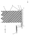
- Zur Verdeutlichung des generellen Aufbaus einer erfindungsgemäßen Bereitstellungseinrichtung sowie eines erfindungsgemäßen Bereitstellungssystems wird zunächst auf
Fig. 1 eingegangen. Hier ist ersichtlich, dass eine Anschlusseinrichtung 10 unterhalb einer Fixierungseinrichtung 40, die hier als Tür ausgeführt ist, im Türspalt 41 angeordnet ist. Die Anschlusseinrichtung 10 ist hier in ihrem senkrecht zur Türblattebene verlaufenden translatorischen Freiheitsgrad 60 blockiert, wie in Bezug auf dieFiguren 2 und3 noch erklärt werden wird. - Durch die Blockierung des translatorischen Freiheitsgrades 60 kann die Anschlusseinrichtung 10 nicht vom Fixierungselement 40 entfernt werden, wenn Diese, als Tür ausgeführt, nicht geöffnet wird.
- In einem als Öse ausgestalteten zweiten Formelement 12 der Anschlusseinrichtung 10 ist eine erste Schlaufe 71, die an einem Ende eines als Seil ausgestalteten Verbindungselements 70 angeordnet ist, hindurch gefädelt, und das Verbindungselement 70 ist durch diese erste Schlaufe 71 hindurch gefädelt. Dadurch ist eine sehr einfache mechanische Verbindung zwischen dem Verbindungselement 70 und der Anschlusseinrichtung 10 realisiert, die bei Freilegung der Anschlusseinrichtung 10 durch Öffnung des als Tür ausgestatteten Fixierungselementes 40 leicht manuell lösbar ist. Zu diesem Zweck wird die befreite Anschlusseinrichtung 10 durch die erste Schlaufe 71 gefädelt, so dass die erste Schlaufe 71 auch wieder aus dem ösenartigen zweiten Formelement 12 herausgezogen werden kann. Somit liegt das eine Ende des seilartigen Verbindungselementes 70 frei. Das Verbindungselement 70 weist an seinem der Anschlusseinrichtung 10 gegenüberliegenden Ende eine zweite Schlaufe 72 auf, in der eine Verschlusseinrichtung 80, hier ein Form eines Vorhängeschlosses, eingehängt und verschlossen ist. Das Verbindungselement 70 führt durch eine Aufnahmeöse 33 der Liefereinheit 30, wobei diese Aufnahmeöse 33 am Behälter 32 der Liefereinheit 30 angeordnet ist. Die Liefereinheit 30 umfasst außerdem einen den Behälter 32 abdeckenden bzw. schließenden Deckel 31, an dem ein schwenkbares Komplementärteil 34 angeordnet ist. Das Komplementärteil 34 ist so über die Aufnahmeöse 33 geschwenkt, dass die Aufnahmeöse 33 und das Komplementärteil 34 zusammen einen Kistenverschluss ausbilden.
- Das seilartige Verbindungselement 70 führt durch die Aufnahmeöse 33, so dass das Komplementärteil 34 nicht geschwenkt werden kann und somit der Deckel 31 auf dem Behälter 32 fixiert ist. Dadurch, dass in der zweiten Schlaufe 72 das Verbindungselementes 70 die Verschlusseinrichtung 80 eingehängt ist, lässt sich das Verbindungselement 70 nicht aus der Aufnahmeöse 33 herausziehen, so dass die Liefereinheit 33 verschlossen ist und, in der
Fig. 1 dargestellten Ausführungsform, bei geschlossenem Fixierungselement 40 unlösbar mit diesem Fixierungselement 40 sowie mit der daran angeschlossenen Anschlusseinrichtung 10 verbunden ist. - Erfolgt nun wie beschrieben die Freilegung der Anschlusseinrichtung 10 sowie die Befreiung der ersten Schlaufe 71 des Verbindungselementes 70, lässt sich das Verbindungselement 70 auch aus der Aufnahmeöse 33 herausziehen, so dass die Liefereinheit 30 frei beweglich ist und das Komplementärteil 34 von der Aufnahme 33 weggeschwenkt werden kann und der Deckel 31 vom Behälter 32 abnehmbar ist, so dass die belieferte Person den Inhalt der Liefereinheit 30 in Besitz nehmen kann.
- Zwecks Blockierung des translatorischen Freiheitsgrades 60 ist, wie in den
Figuren 2 und3 dargestellt, die Anschlusseinrichtung 10 mit einem ersten Formelement 11 ausgestaltet, welches eine formschlüssige Verbindung mit dem Türblatt des Fixierungselementes 40 ausbilden kann. Dieses erste Formelement ist bevorzugt ein Winkelprofil, insbesondere ein dargestelltes U-Profil 20, dessen dem zweiten Formelement 12 abgewandter Schenkel als Blockadeelement 21 ausgestaltet ist. - Dadurch lässt sich, wie in
Fig. 3 dargestellt, die Anschlusseinrichtung 10 derart in einem Türspalt 41 anordnen, dass das U-Profil 20 das Fixierungselement 40 an seinem Randbereich umgreift, wobei das Blockadeelement 21 die Bewegung der Anschlusseinrichtung 10 in einer Richtung des translatorischen Freiheitsgrades 60, nämlich in Richtung des zweiten Formelementes 12, verhindert, so dass die Anschlusseinrichtung 10 nur von dem Fixierungselement 40 entfernt werden kann, wenn dieses Fixierungselement 40 in eine Position bewegt wird, in der die Anschlusseinrichtung 10 entfernbar ist. Bei einer Ausgestaltung des Fixierungselementes 40 als Tür ist diese Position die Stellung der Tür außerhalb des Türrahmens, in der die Anschlusseinrichtung 10 in einfacher Weise unter die geöffnete Tür schiebbar bzw. von dort wegbewegbar ist. -
- Anschlusseinrichtung
- 10
- erstes Formelement
- 11
- zweites Formelement
- 12
- U-Profil
- 20
- Blockadeelement
- 21
- Mittelteil
- 22
- Liefereinheit
- 30
- Deckel
- 31
- Behälter
- 32
- Aufnahmeöse
- 33
- Komplementärteil
- 34
- Fixierungselement
- 40
- Türspalt Sperreinheit
- 50
- translatorischer Freiheitsgrad
- 60
- Verbindungselement
- 70
- erste Schlaufe
- 71
- zweite Schlaufe
- 72
- Verschlusseinrichtung
- 80
Claims (11)
- Bereitstellungseinrichtung zur Bereitstellung einer Liefereinheit (30), umfassend eine Anschlusseinrichtung (10) zur mechanischen Sicherung der Liefereinheit (30), wobei die Anschlusseinrichtung (10) ein erstes Formelement (11) aufweist, welches form- und/ oder kraftschlüssig mit einem positionsgesicherten Fixierungselement (40) mechanisch verbindbar oder verbunden ist; und die Anschlusseinrichtung (10) mit dem Fixierungselement (40) derart in Wirkverbindung bringbar oder gebracht ist, dass die Anschlusseinrichtung (10) und das Fixierungselement (40) zusammen eine Sperreinheit (50) ausbilden, deren Öffnung einen Zugangsberechtigungsnachweis erfordert,
sowie umfassend die Liefereinheit (30), die mit der Anschlusseinrichtung (10) mechanisch verbunden oder verbindbar ist, wobei die Anschlusseinrichtung (10) ein zweites Formelement (12) aufweist zur Realisierung einer kraft- und/oder formschlüssigen Verbindung zur zu sichernden Liefereinheit (30), wobei das zweite Formelement (12) als eine Öse ausgestaltet ist und die Bereitstellungseinrichtung ein Verbindungselement (70) zur Realisierung einer mechanischen Verbindung zwischen der Liefereinheit (30) und der Anschlusseinrichtung (10) aufweist, wobei das Verbindungselement (70) ein Seil mit wenigstens einer an einem Ende angeordneten Schlaufe (71) ist, dadurch gekennzeichnet, dass die Schlaufe (71) durch die Öse hindurch gezogen ist und das Seil durch diese Schlaufe (71) hindurch gezogen ist. - Bereitstellungseinrichtung nach Anspruch 1, dadurch gekennzeichnet, dass die Anschlusseinrichtung (10) ein erstes Formelement (11) aufweist, welches form- und/ oder kraftschlüssig derart an einem Türblatt einer Tür anordbar oder angeordnet ist, dass der Anschlusseinrichtung (10) bei geschlossener Tür wenigstens der translatorische Freiheitsgrad (60) senkrecht zur Türblattebene genommen ist.
- Bereitstellungseinrichtung nach Anspruch 2, dadurch gekennzeichnet, dass das erste Formelement (11) der Anschlusseinrichtung (10) zumindest bereichsweise im Wesentlichen den Querschnitt eines U-Profils (20) aufweist, wobei einer der Schenkel des U-Profils (20) als Blockadeelement (21) ausgeführt ist.
- Bereitstellungseinrichtung nach Anspruch 1, dadurch gekennzeichnet, dass die Anschlusseinrichtung (10) ein erstes Formelement (11) aufweist, welches form- und/ oder kraftschlüssig derart in einem Schlitz eines Briefkastens anordbar oder angeordnet ist, dass der Anschlusseinrichtung (10) bei geschlossenem Briefkasten wenigstens der translatorische Freiheitsgrad (60) senkrecht zu der Ebene genommen ist, in der sich der Briefkastenschlitz erstreckt.
- Bereitstellungseinrichtung nach Anspruch 1, dadurch gekennzeichnet, dass die Anschlusseinrichtung (10) ver- und entriegelbar ist und ein erstes Formelement (11) aufweist, welches form- und/ oder kraftschlüssig derart an einem Element eines Gartentores oder Gartenzaunes anschließbar oder angeschlossen ist, dass die Anschlusseinrichtung (10) im verriegelten Zustand am Gartentor bzw. Gartenzaun fixiert ist.
- Bereitstellungseinrichtung nach einem der vorhergehenden Ansprüche, dadurch gekennzeichnet, dass das Verbindungselement (70) ein Seil mit beidendig angeordneten Schlaufen (71,72) ist, wobei die zweite Schlaufe (72) mittels einer Verschlusseinrichtung (80) an einem Formelement der Liefereinheit kraft- und/ oder formschlüssig gegen Wegnahme gesichert ist.
- Bereitstellungseinrichtung nach Anspruch 6, dadurch gekennzeichnet, dass die Verschlusseinrichtung (80) ein Vorhängeschloss ist, wobei die zweite Schlaufe (72) des Seiles durch eine Aufnahmeöse (33) der Liefereinheit (30) hindurch gezogen ist und das Vorhängeschloss in die zweite Schlaufe (72) eingehängt und verschlossen ist, wobei die maximale lichte Weite der Aufnahmeöse (33) der Liefereinheit (30) geringer ist als die minimale räumliche Erstreckung des Vorhängeschlosses.
- Bereitstellungseinrichtung nach Anspruch 7, dadurch gekennzeichnet, dass die Liefereinheit (30) einen Deckel (31) und einen Behälter (32) aufweist, wobei an einem der Elemente Deckel (31) und Behälter (32) die Aufnahmeöse (33) angeordnet ist und am jeweils anderen Element ein Komplementärteil (34) angeordnet ist, welches in seiner Position im Wesentlichen fixierbar ist, wenn sich ein Gegenstand, wie z.B. das Seil, durch die Aufnahmeöse (33) erstreckt.
- Bereitstellungssystem, umfassend eine Bereitstellungseinrichtung nach einem der Ansprüche 1 bis 8 sowie ein Fixierungselement 40, das mit der Anschlusseinrichtung (10) der Bereitstellungseinrichtung derart in Wirkverbindung gebracht ist, dass die Anschlusseinrichtung (10) und das Fixierungselement (40) zusammen eine Sperreinheit (50) ausbilden, deren Öffnung einen Zugangsberechtigungsnachweis erfordert.
- Verfahren zur Bereitstellung einer Liefereinheit, bei dem ein Bereitstellungssystem nach Anspruch 9 genutzt wird, um eine Liefereinheit (30) mittels der Anschlusseinrichtung (10) an das Fixierungselement (40) mechanisch anzuschließen, wobei eine mechanische Verbindung zwischen der Anschlusseinrichtung (10) und der Liefereinheit (30) hergestellt wird.
- Verfahren zur Bereitstellung einer Liefereinheit (30) nach Anspruch 10, dadurch gekennzeichnet, dass die Anschlusseinrichtung (10) als zweites Formelement (12) eine Öse aufweist und die Bereitstellungseinrichtung weiterhin zwischen der Anschlusseinrichtung (10) und der Liefereinheit (30) ein Verbindungselement (70) aufweist, welches ein Seil mit beidendig angeordneten Schlaufen (71,72) ist; und dass die Liefereinheit (30) einen Deckel (31) und einen Behälter (32) aufweist, wobei an einem der Elemente Deckel (31) und Behälter (32) eine Aufnahmeöse (33) angeordnet ist und am jeweils anderen Element ein Komplementärteil (34) angeordnet ist, welches in seiner Position im Wesentlichen fixierbar ist, wenn sich ein Gegenstand durch die Aufnahmeöse (33) erstreckt,
wobei eine erste Schlaufe (71) des Seils durch die Öse der Anschlusseinrichtung (10) gesteckt wird und das Verbindungselement (70) danach durch die erste Schlaufe (71) gefädelt wird und die zweite Schlaufe (72) des Seils durch die Aufnahmeöse (33) der Liefereinheit (30) gezogen wird und danach ein Vorhängeschloss in die zweite Schlaufe (72) eingehängt und verriegelt wird.
Priority Applications (1)
| Application Number | Priority Date | Filing Date | Title |
|---|---|---|---|
| PL14075022T PL2801302T3 (pl) | 2013-05-08 | 2014-04-14 | Urządzenie udostępniające, system udostępniania i sposób udostępniania jednostki dostawczej |
Applications Claiming Priority (1)
| Application Number | Priority Date | Filing Date | Title |
|---|---|---|---|
| DE201310104755 DE102013104755B4 (de) | 2013-05-08 | 2013-05-08 | Bereitstellungseinrichtung, Bereitstellungssystem und Verfahren zur Bereitstellung einer Liefereinheit |
Publications (2)
| Publication Number | Publication Date |
|---|---|
| EP2801302A1 EP2801302A1 (de) | 2014-11-12 |
| EP2801302B1 true EP2801302B1 (de) | 2016-10-19 |
Family
ID=50543421
Family Applications (1)
| Application Number | Title | Priority Date | Filing Date |
|---|---|---|---|
| EP14075022.5A Not-in-force EP2801302B1 (de) | 2013-05-08 | 2014-04-14 | Bereitstellungseinrichtung, Bereitstellungssystem und Verfahren zur Bereitstellung einer Liefereinheit |
Country Status (6)
| Country | Link |
|---|---|
| EP (1) | EP2801302B1 (de) |
| DE (1) | DE102013104755B4 (de) |
| DK (1) | DK2801302T3 (de) |
| ES (1) | ES2619607T3 (de) |
| PL (1) | PL2801302T3 (de) |
| PT (1) | PT2801302T (de) |
Cited By (1)
| Publication number | Priority date | Publication date | Assignee | Title |
|---|---|---|---|---|
| US10583853B2 (en) | 2018-02-22 | 2020-03-10 | John Brilhante | Delivered package securment system |
Families Citing this family (5)
| Publication number | Priority date | Publication date | Assignee | Title |
|---|---|---|---|---|
| DE102014110688B4 (de) * | 2014-07-29 | 2017-04-20 | Reiner Probst | Vorrichtung zur Aufnahme von Paketen oder anderen Lieferungen |
| LT6451B (lt) | 2016-01-18 | 2017-09-11 | Uab "Zzz.Lt" | Siuntinių dėžės saugus užrakinimo įtaisas ir būdas |
| DE102017208050A1 (de) | 2017-05-12 | 2018-11-15 | Ford Global Technologies, Llc | System und Verfahren zum Ausliefern und/oder Abholen von Paketen |
| US10383471B1 (en) | 2018-07-31 | 2019-08-20 | Pristtine, Inc. | Package protecting delivery receptacle with expandable attachment bracket |
| US10932602B2 (en) * | 2018-09-20 | 2021-03-02 | Jerry L. Hauck | Theft prevention package containers |
Family Cites Families (4)
| Publication number | Priority date | Publication date | Assignee | Title |
|---|---|---|---|---|
| ES2140308B1 (es) * | 1997-07-07 | 2000-10-16 | Butano Ormad S L | Dispositivo-monedero con pletina de sustentacion y sirga para sujecion de botellas de butano. |
| GB2340479A (en) * | 1998-08-11 | 2000-02-23 | Butler Boxes Limited | Container lockable to an anchorage point |
| GB2424919B (en) * | 2005-03-24 | 2009-09-23 | Peter Bruce Kerr | A device for securing a container in a particular place |
| US9926108B2 (en) * | 2011-09-28 | 2018-03-27 | Gloria Selena Wiley | Secure unattended delivery apparatus |
-
2013
- 2013-05-08 DE DE201310104755 patent/DE102013104755B4/de not_active Expired - Fee Related
-
2014
- 2014-04-14 ES ES14075022.5T patent/ES2619607T3/es active Active
- 2014-04-14 PL PL14075022T patent/PL2801302T3/pl unknown
- 2014-04-14 DK DK14075022.5T patent/DK2801302T3/en active
- 2014-04-14 PT PT140750225T patent/PT2801302T/pt unknown
- 2014-04-14 EP EP14075022.5A patent/EP2801302B1/de not_active Not-in-force
Cited By (1)
| Publication number | Priority date | Publication date | Assignee | Title |
|---|---|---|---|---|
| US10583853B2 (en) | 2018-02-22 | 2020-03-10 | John Brilhante | Delivered package securment system |
Also Published As
| Publication number | Publication date |
|---|---|
| DE102013104755B4 (de) | 2015-05-13 |
| PL2801302T3 (pl) | 2017-07-31 |
| EP2801302A1 (de) | 2014-11-12 |
| ES2619607T3 (es) | 2017-06-26 |
| DK2801302T3 (en) | 2017-01-30 |
| DE102013104755A1 (de) | 2014-11-13 |
| PT2801302T (pt) | 2017-01-31 |
Similar Documents
| Publication | Publication Date | Title |
|---|---|---|
| EP2801302B1 (de) | Bereitstellungseinrichtung, Bereitstellungssystem und Verfahren zur Bereitstellung einer Liefereinheit | |
| DE2920990C2 (de) | Schiebefenster mit mindestens einem horizontal verschiebbaren Schiebeflügel, dem eine Sicherheitseinrichtung gegen seine Entnahme zugeordnet ist | |
| EP2746496A2 (de) | Sicherungsvorrichtung für einen Fenster- oder Türgriff | |
| EP3075288A1 (de) | Vorrichtung zur verriegelung des paketfachs eines briefkastens und eine verwendung der vorrichtung | |
| DE202015104085U1 (de) | An einen Fahrrad-Gepäckträger anschließbares Gepäckstück | |
| EP1705332A1 (de) | Verschließbarer Kasten | |
| DE102010003641A1 (de) | Befestigungsvorrichtung für einen Motorradhelm | |
| DE102017002954A1 (de) | Postempfangsbox für die Aufnahme von Postsendungen an Wohnungstüren | |
| DE19629619C2 (de) | Bewegliche Schutzwand | |
| DE102017003453B4 (de) | Sperrvorrichtung für einen Betätiger einer Sicherheitszuhaltung | |
| EP0887250A2 (de) | Halterung für Behälter im allgemeinen und Aktenkoffer im besonderen, geeignet für Motorräder und dergleichen | |
| DE102010015476A1 (de) | Verriegelungsvorrichtung für ein Ladestellentor | |
| DE102015002277B4 (de) | Briefkasten für einen Gitterstabzaun | |
| DE102017009642A1 (de) | Verriegelung | |
| EP0535503A1 (de) | Vorrichtung zum Sichern von zwei Türen | |
| DE7247564U (de) | Vorrichtung zur Sicherung von Automaten u dgl, wie insbesondere Geld Spielautomaten, gegen Aufbrechen | |
| DE102010003155B4 (de) | Briefkasten oder Briefkastenanlage mit einer Einwurfsperre zum Verschließen der Einwurföffnung | |
| DE202007014456U1 (de) | Einwurfsperre für Briefkästen u.dgl. | |
| DE2913112A1 (de) | Sicherung fuer ein abdeckgitter eines kellerfensterschachts | |
| DE202006012866U1 (de) | Verschließbarer Sicherheitsbehälter | |
| DE202007004472U1 (de) | Wertbehältnis und Vorrichtung zum Einbringen von Gegenständen in Wertbehältnisse | |
| DE202013105346U1 (de) | Grabmal | |
| DE29513923U1 (de) | Vorrichtung zur Sicherung von Fenstern, Türen u.dgl. | |
| DE29823638U1 (de) | Diebstahlsicherung für Abrollcontainer | |
| DE8715741U1 (de) | Sicherheitseinrichtung an Münzsammlern |
Legal Events
| Date | Code | Title | Description |
|---|---|---|---|
| PUAI | Public reference made under article 153(3) epc to a published international application that has entered the european phase |
Free format text: ORIGINAL CODE: 0009012 |
|
| 17P | Request for examination filed |
Effective date: 20140414 |
|
| AK | Designated contracting states |
Kind code of ref document: A1 Designated state(s): AL AT BE BG CH CY CZ DE DK EE ES FI FR GB GR HR HU IE IS IT LI LT LU LV MC MK MT NL NO PL PT RO RS SE SI SK SM TR |
|
| AX | Request for extension of the european patent |
Extension state: BA ME |
|
| R17P | Request for examination filed (corrected) |
Effective date: 20150121 |
|
| RBV | Designated contracting states (corrected) |
Designated state(s): AL AT BE BG CH CY CZ DE DK EE ES FI FR GB GR HR HU IE IS IT LI LT LU LV MC MK MT NL NO PL PT RO RS SE SI SK SM TR |
|
| GRAP | Despatch of communication of intention to grant a patent |
Free format text: ORIGINAL CODE: EPIDOSNIGR1 |
|
| RIC1 | Information provided on ipc code assigned before grant |
Ipc: A47G 29/20 20060101AFI20160406BHEP |
|
| RIN1 | Information on inventor provided before grant (corrected) |
Inventor name: KRAKER VON SCHWARZENFELD, THOMAS |
|
| INTG | Intention to grant announced |
Effective date: 20160506 |
|
| GRAS | Grant fee paid |
Free format text: ORIGINAL CODE: EPIDOSNIGR3 |
|
| GRAA | (expected) grant |
Free format text: ORIGINAL CODE: 0009210 |
|
| AK | Designated contracting states |
Kind code of ref document: B1 Designated state(s): AL AT BE BG CH CY CZ DE DK EE ES FI FR GB GR HR HU IE IS IT LI LT LU LV MC MK MT NL NO PL PT RO RS SE SI SK SM TR |
|
| REG | Reference to a national code |
Ref country code: GB Ref legal event code: FG4D Free format text: NOT ENGLISH |
|
| REG | Reference to a national code |
Ref country code: CH Ref legal event code: EP |
|
| REG | Reference to a national code |
Ref country code: AT Ref legal event code: REF Ref document number: 837584 Country of ref document: AT Kind code of ref document: T Effective date: 20161115 |
|
| REG | Reference to a national code |
Ref country code: IE Ref legal event code: FG4D Free format text: LANGUAGE OF EP DOCUMENT: GERMAN |
|
| REG | Reference to a national code |
Ref country code: DE Ref legal event code: R096 Ref document number: 502014001723 Country of ref document: DE |
|
| REG | Reference to a national code |
Ref country code: NO Ref legal event code: T2 Effective date: 20161019 |
|
| REG | Reference to a national code |
Ref country code: DK Ref legal event code: T3 Effective date: 20170127 |
|
| REG | Reference to a national code |
Ref country code: PT Ref legal event code: SC4A Ref document number: 2801302 Country of ref document: PT Date of ref document: 20170131 Kind code of ref document: T Free format text: AVAILABILITY OF NATIONAL TRANSLATION Effective date: 20170118 |
|
| REG | Reference to a national code |
Ref country code: NL Ref legal event code: FP |
|
| REG | Reference to a national code |
Ref country code: SE Ref legal event code: TRGR |
|
| REG | Reference to a national code |
Ref country code: LT Ref legal event code: MG4D |
|
| PG25 | Lapsed in a contracting state [announced via postgrant information from national office to epo] |
Ref country code: LV Free format text: LAPSE BECAUSE OF FAILURE TO SUBMIT A TRANSLATION OF THE DESCRIPTION OR TO PAY THE FEE WITHIN THE PRESCRIBED TIME-LIMIT Effective date: 20161019 |
|
| REG | Reference to a national code |
Ref country code: FR Ref legal event code: PLFP Year of fee payment: 4 |
|
| PG25 | Lapsed in a contracting state [announced via postgrant information from national office to epo] |
Ref country code: GR Free format text: LAPSE BECAUSE OF FAILURE TO SUBMIT A TRANSLATION OF THE DESCRIPTION OR TO PAY THE FEE WITHIN THE PRESCRIBED TIME-LIMIT Effective date: 20170120 Ref country code: LT Free format text: LAPSE BECAUSE OF FAILURE TO SUBMIT A TRANSLATION OF THE DESCRIPTION OR TO PAY THE FEE WITHIN THE PRESCRIBED TIME-LIMIT Effective date: 20161019 |
|
| PG25 | Lapsed in a contracting state [announced via postgrant information from national office to epo] |
Ref country code: RS Free format text: LAPSE BECAUSE OF FAILURE TO SUBMIT A TRANSLATION OF THE DESCRIPTION OR TO PAY THE FEE WITHIN THE PRESCRIBED TIME-LIMIT Effective date: 20161019 Ref country code: HR Free format text: LAPSE BECAUSE OF FAILURE TO SUBMIT A TRANSLATION OF THE DESCRIPTION OR TO PAY THE FEE WITHIN THE PRESCRIBED TIME-LIMIT Effective date: 20161019 Ref country code: IS Free format text: LAPSE BECAUSE OF FAILURE TO SUBMIT A TRANSLATION OF THE DESCRIPTION OR TO PAY THE FEE WITHIN THE PRESCRIBED TIME-LIMIT Effective date: 20170219 Ref country code: FI Free format text: LAPSE BECAUSE OF FAILURE TO SUBMIT A TRANSLATION OF THE DESCRIPTION OR TO PAY THE FEE WITHIN THE PRESCRIBED TIME-LIMIT Effective date: 20161019 |
|
| REG | Reference to a national code |
Ref country code: ES Ref legal event code: FG2A Ref document number: 2619607 Country of ref document: ES Kind code of ref document: T3 Effective date: 20170626 |
|
| REG | Reference to a national code |
Ref country code: DE Ref legal event code: R097 Ref document number: 502014001723 Country of ref document: DE |
|
| PG25 | Lapsed in a contracting state [announced via postgrant information from national office to epo] |
Ref country code: RO Free format text: LAPSE BECAUSE OF FAILURE TO SUBMIT A TRANSLATION OF THE DESCRIPTION OR TO PAY THE FEE WITHIN THE PRESCRIBED TIME-LIMIT Effective date: 20161019 Ref country code: SK Free format text: LAPSE BECAUSE OF FAILURE TO SUBMIT A TRANSLATION OF THE DESCRIPTION OR TO PAY THE FEE WITHIN THE PRESCRIBED TIME-LIMIT Effective date: 20161019 Ref country code: EE Free format text: LAPSE BECAUSE OF FAILURE TO SUBMIT A TRANSLATION OF THE DESCRIPTION OR TO PAY THE FEE WITHIN THE PRESCRIBED TIME-LIMIT Effective date: 20161019 |
|
| PLBE | No opposition filed within time limit |
Free format text: ORIGINAL CODE: 0009261 |
|
| STAA | Information on the status of an ep patent application or granted ep patent |
Free format text: STATUS: NO OPPOSITION FILED WITHIN TIME LIMIT |
|
| PG25 | Lapsed in a contracting state [announced via postgrant information from national office to epo] |
Ref country code: SM Free format text: LAPSE BECAUSE OF FAILURE TO SUBMIT A TRANSLATION OF THE DESCRIPTION OR TO PAY THE FEE WITHIN THE PRESCRIBED TIME-LIMIT Effective date: 20161019 Ref country code: BG Free format text: LAPSE BECAUSE OF FAILURE TO SUBMIT A TRANSLATION OF THE DESCRIPTION OR TO PAY THE FEE WITHIN THE PRESCRIBED TIME-LIMIT Effective date: 20170119 |
|
| 26N | No opposition filed |
Effective date: 20170720 |
|
| PG25 | Lapsed in a contracting state [announced via postgrant information from national office to epo] |
Ref country code: SI Free format text: LAPSE BECAUSE OF FAILURE TO SUBMIT A TRANSLATION OF THE DESCRIPTION OR TO PAY THE FEE WITHIN THE PRESCRIBED TIME-LIMIT Effective date: 20161019 |
|
| REG | Reference to a national code |
Ref country code: IE Ref legal event code: MM4A |
|
| PG25 | Lapsed in a contracting state [announced via postgrant information from national office to epo] |
Ref country code: MC Free format text: LAPSE BECAUSE OF FAILURE TO SUBMIT A TRANSLATION OF THE DESCRIPTION OR TO PAY THE FEE WITHIN THE PRESCRIBED TIME-LIMIT Effective date: 20161019 |
|
| REG | Reference to a national code |
Ref country code: FR Ref legal event code: PLFP Year of fee payment: 5 |
|
| PG25 | Lapsed in a contracting state [announced via postgrant information from national office to epo] |
Ref country code: IE Free format text: LAPSE BECAUSE OF NON-PAYMENT OF DUE FEES Effective date: 20170414 |
|
| PGFP | Annual fee paid to national office [announced via postgrant information from national office to epo] |
Ref country code: LU Payment date: 20180423 Year of fee payment: 5 Ref country code: NL Payment date: 20180423 Year of fee payment: 5 |
|
| PGFP | Annual fee paid to national office [announced via postgrant information from national office to epo] |
Ref country code: DK Payment date: 20180424 Year of fee payment: 5 Ref country code: ES Payment date: 20180523 Year of fee payment: 5 Ref country code: CH Payment date: 20180424 Year of fee payment: 5 Ref country code: DE Payment date: 20180423 Year of fee payment: 5 |
|
| PGFP | Annual fee paid to national office [announced via postgrant information from national office to epo] |
Ref country code: BE Payment date: 20180423 Year of fee payment: 5 Ref country code: FR Payment date: 20180424 Year of fee payment: 5 Ref country code: IT Payment date: 20180420 Year of fee payment: 5 |
|
| PG25 | Lapsed in a contracting state [announced via postgrant information from national office to epo] |
Ref country code: MT Free format text: LAPSE BECAUSE OF FAILURE TO SUBMIT A TRANSLATION OF THE DESCRIPTION OR TO PAY THE FEE WITHIN THE PRESCRIBED TIME-LIMIT Effective date: 20161019 |
|
| PGFP | Annual fee paid to national office [announced via postgrant information from national office to epo] |
Ref country code: SE Payment date: 20180424 Year of fee payment: 5 |
|
| PGFP | Annual fee paid to national office [announced via postgrant information from national office to epo] |
Ref country code: GB Payment date: 20180424 Year of fee payment: 5 |
|
| PG25 | Lapsed in a contracting state [announced via postgrant information from national office to epo] |
Ref country code: HU Free format text: LAPSE BECAUSE OF FAILURE TO SUBMIT A TRANSLATION OF THE DESCRIPTION OR TO PAY THE FEE WITHIN THE PRESCRIBED TIME-LIMIT; INVALID AB INITIO Effective date: 20140414 |
|
| PGFP | Annual fee paid to national office [announced via postgrant information from national office to epo] |
Ref country code: PT Payment date: 20190405 Year of fee payment: 6 Ref country code: PL Payment date: 20190404 Year of fee payment: 6 Ref country code: NO Payment date: 20190423 Year of fee payment: 6 Ref country code: CZ Payment date: 20190403 Year of fee payment: 6 |
|
| PG25 | Lapsed in a contracting state [announced via postgrant information from national office to epo] |
Ref country code: CY Free format text: LAPSE BECAUSE OF FAILURE TO SUBMIT A TRANSLATION OF THE DESCRIPTION OR TO PAY THE FEE WITHIN THE PRESCRIBED TIME-LIMIT Effective date: 20161019 |
|
| PGFP | Annual fee paid to national office [announced via postgrant information from national office to epo] |
Ref country code: AT Payment date: 20190416 Year of fee payment: 6 |
|
| REG | Reference to a national code |
Ref country code: DE Ref legal event code: R119 Ref document number: 502014001723 Country of ref document: DE |
|
| PG25 | Lapsed in a contracting state [announced via postgrant information from national office to epo] |
Ref country code: MK Free format text: LAPSE BECAUSE OF FAILURE TO SUBMIT A TRANSLATION OF THE DESCRIPTION OR TO PAY THE FEE WITHIN THE PRESCRIBED TIME-LIMIT Effective date: 20161019 |
|
| REG | Reference to a national code |
Ref country code: CH Ref legal event code: PL |
|
| REG | Reference to a national code |
Ref country code: DK Ref legal event code: EBP Effective date: 20190430 |
|
| REG | Reference to a national code |
Ref country code: SE Ref legal event code: EUG |
|
| REG | Reference to a national code |
Ref country code: NL Ref legal event code: MM Effective date: 20190501 |
|
| REG | Reference to a national code |
Ref country code: BE Ref legal event code: MM Effective date: 20190430 |
|
| GBPC | Gb: european patent ceased through non-payment of renewal fee |
Effective date: 20190414 |
|
| PG25 | Lapsed in a contracting state [announced via postgrant information from national office to epo] |
Ref country code: LU Free format text: LAPSE BECAUSE OF NON-PAYMENT OF DUE FEES Effective date: 20190414 |
|
| PG25 | Lapsed in a contracting state [announced via postgrant information from national office to epo] |
Ref country code: DE Free format text: LAPSE BECAUSE OF NON-PAYMENT OF DUE FEES Effective date: 20191101 Ref country code: CH Free format text: LAPSE BECAUSE OF NON-PAYMENT OF DUE FEES Effective date: 20190430 Ref country code: NL Free format text: LAPSE BECAUSE OF NON-PAYMENT OF DUE FEES Effective date: 20190501 Ref country code: SE Free format text: LAPSE BECAUSE OF NON-PAYMENT OF DUE FEES Effective date: 20190415 Ref country code: GB Free format text: LAPSE BECAUSE OF NON-PAYMENT OF DUE FEES Effective date: 20190414 Ref country code: LI Free format text: LAPSE BECAUSE OF NON-PAYMENT OF DUE FEES Effective date: 20190430 |
|
| PG25 | Lapsed in a contracting state [announced via postgrant information from national office to epo] |
Ref country code: FR Free format text: LAPSE BECAUSE OF NON-PAYMENT OF DUE FEES Effective date: 20190430 Ref country code: BE Free format text: LAPSE BECAUSE OF NON-PAYMENT OF DUE FEES Effective date: 20190430 |
|
| PG25 | Lapsed in a contracting state [announced via postgrant information from national office to epo] |
Ref country code: TR Free format text: LAPSE BECAUSE OF FAILURE TO SUBMIT A TRANSLATION OF THE DESCRIPTION OR TO PAY THE FEE WITHIN THE PRESCRIBED TIME-LIMIT Effective date: 20161019 |
|
| PG25 | Lapsed in a contracting state [announced via postgrant information from national office to epo] |
Ref country code: IT Free format text: LAPSE BECAUSE OF NON-PAYMENT OF DUE FEES Effective date: 20190414 Ref country code: DK Free format text: LAPSE BECAUSE OF NON-PAYMENT OF DUE FEES Effective date: 20190430 |
|
| PG25 | Lapsed in a contracting state [announced via postgrant information from national office to epo] |
Ref country code: AL Free format text: LAPSE BECAUSE OF FAILURE TO SUBMIT A TRANSLATION OF THE DESCRIPTION OR TO PAY THE FEE WITHIN THE PRESCRIBED TIME-LIMIT Effective date: 20161019 |
|
| REG | Reference to a national code |
Ref country code: ES Ref legal event code: FD2A Effective date: 20200828 |
|
| PG25 | Lapsed in a contracting state [announced via postgrant information from national office to epo] |
Ref country code: ES Free format text: LAPSE BECAUSE OF NON-PAYMENT OF DUE FEES Effective date: 20190415 |
|
| REG | Reference to a national code |
Ref country code: NO Ref legal event code: MMEP |
|
| REG | Reference to a national code |
Ref country code: AT Ref legal event code: MM01 Ref document number: 837584 Country of ref document: AT Kind code of ref document: T Effective date: 20200414 |
|
| PG25 | Lapsed in a contracting state [announced via postgrant information from national office to epo] |
Ref country code: PT Free format text: LAPSE BECAUSE OF NON-PAYMENT OF DUE FEES Effective date: 20201014 Ref country code: AT Free format text: LAPSE BECAUSE OF NON-PAYMENT OF DUE FEES Effective date: 20200414 Ref country code: NO Free format text: LAPSE BECAUSE OF NON-PAYMENT OF DUE FEES Effective date: 20200430 Ref country code: CZ Free format text: LAPSE BECAUSE OF NON-PAYMENT OF DUE FEES Effective date: 20200414 |
|
| PG25 | Lapsed in a contracting state [announced via postgrant information from national office to epo] |
Ref country code: PL Free format text: LAPSE BECAUSE OF NON-PAYMENT OF DUE FEES Effective date: 20200414 |