EP2801198B1 - Traitement de séquences d'images 3d - Google Patents
Traitement de séquences d'images 3d Download PDFInfo
- Publication number
- EP2801198B1 EP2801198B1 EP12824849.9A EP12824849A EP2801198B1 EP 2801198 B1 EP2801198 B1 EP 2801198B1 EP 12824849 A EP12824849 A EP 12824849A EP 2801198 B1 EP2801198 B1 EP 2801198B1
- Authority
- EP
- European Patent Office
- Prior art keywords
- image pair
- parallax
- stereoscopic
- image
- frame
- Prior art date
- Legal status (The legal status is an assumption and is not a legal conclusion. Google has not performed a legal analysis and makes no representation as to the accuracy of the status listed.)
- Active
Links
- 238000012545 processing Methods 0.000 title description 5
- 238000000034 method Methods 0.000 claims description 49
- 239000000872 buffer Substances 0.000 claims description 23
- 238000005562 fading Methods 0.000 claims description 3
- 230000003247 decreasing effect Effects 0.000 claims 2
- 238000009499 grossing Methods 0.000 description 80
- 230000007704 transition Effects 0.000 description 55
- 230000008569 process Effects 0.000 description 36
- 230000008859 change Effects 0.000 description 17
- 238000010586 diagram Methods 0.000 description 17
- 230000002123 temporal effect Effects 0.000 description 12
- 230000009467 reduction Effects 0.000 description 11
- 230000004048 modification Effects 0.000 description 10
- 238000012986 modification Methods 0.000 description 10
- 230000000694 effects Effects 0.000 description 9
- 230000006870 function Effects 0.000 description 8
- 238000012937 correction Methods 0.000 description 5
- 210000003128 head Anatomy 0.000 description 4
- 230000009471 action Effects 0.000 description 3
- 238000004891 communication Methods 0.000 description 3
- 230000000007 visual effect Effects 0.000 description 3
- 239000012464 large buffer Substances 0.000 description 2
- 230000007246 mechanism Effects 0.000 description 2
- 230000008447 perception Effects 0.000 description 2
- 229920001690 polydopamine Polymers 0.000 description 2
- 241000282412 Homo Species 0.000 description 1
- 238000013459 approach Methods 0.000 description 1
- 230000008901 benefit Effects 0.000 description 1
- 230000005540 biological transmission Effects 0.000 description 1
- 210000004556 brain Anatomy 0.000 description 1
- 238000006243 chemical reaction Methods 0.000 description 1
- 239000003086 colorant Substances 0.000 description 1
- 230000000254 damaging effect Effects 0.000 description 1
- 230000007423 decrease Effects 0.000 description 1
- 235000012489 doughnuts Nutrition 0.000 description 1
- 238000001914 filtration Methods 0.000 description 1
- 230000003993 interaction Effects 0.000 description 1
- 230000003287 optical effect Effects 0.000 description 1
- 238000009877 rendering Methods 0.000 description 1
- 230000002459 sustained effect Effects 0.000 description 1
- 238000012360 testing method Methods 0.000 description 1
- 230000001052 transient effect Effects 0.000 description 1
Images


Classifications
-
- H—ELECTRICITY
- H04—ELECTRIC COMMUNICATION TECHNIQUE
- H04N—PICTORIAL COMMUNICATION, e.g. TELEVISION
- H04N13/00—Stereoscopic video systems; Multi-view video systems; Details thereof
- H04N13/10—Processing, recording or transmission of stereoscopic or multi-view image signals
- H04N13/106—Processing image signals
- H04N13/128—Adjusting depth or disparity
-
- G—PHYSICS
- G06—COMPUTING; CALCULATING OR COUNTING
- G06T—IMAGE DATA PROCESSING OR GENERATION, IN GENERAL
- G06T7/00—Image analysis
- G06T7/50—Depth or shape recovery
- G06T7/55—Depth or shape recovery from multiple images
- G06T7/593—Depth or shape recovery from multiple images from stereo images
-
- H—ELECTRICITY
- H04—ELECTRIC COMMUNICATION TECHNIQUE
- H04N—PICTORIAL COMMUNICATION, e.g. TELEVISION
- H04N13/00—Stereoscopic video systems; Multi-view video systems; Details thereof
- H04N13/10—Processing, recording or transmission of stereoscopic or multi-view image signals
- H04N13/106—Processing image signals
- H04N13/144—Processing image signals for flicker reduction
-
- G—PHYSICS
- G06—COMPUTING; CALCULATING OR COUNTING
- G06T—IMAGE DATA PROCESSING OR GENERATION, IN GENERAL
- G06T2207/00—Indexing scheme for image analysis or image enhancement
- G06T2207/10—Image acquisition modality
- G06T2207/10016—Video; Image sequence
- G06T2207/10021—Stereoscopic video; Stereoscopic image sequence
-
- H—ELECTRICITY
- H04—ELECTRIC COMMUNICATION TECHNIQUE
- H04N—PICTORIAL COMMUNICATION, e.g. TELEVISION
- H04N2213/00—Details of stereoscopic systems
- H04N2213/002—Eyestrain reduction by processing stereoscopic signals or controlling stereoscopic devices
Definitions
- Implementations are described that relate to stereoscopic video sequences. Various particular implementations relate to adjusting parallax, depth, or disparity in one or more image pairs of a stereoscopic video sequence.
- the European patent EP 0 963 122 published on December 8, 1999 discloses visual image systems and, more particularly, a visual image system in which the degree of three-dimensionality is controlled by estimating effects produced on the observer based on video signals.
- implementations may be configured or embodied in various manners.
- an implementation may be performed as a method, or embodied as an apparatus, such as, for example, an apparatus configured to perform a set of operations or an apparatus storing instructions for performing a set of operations, or embodied in a signal.
- an apparatus such as, for example, an apparatus configured to perform a set of operations or an apparatus storing instructions for performing a set of operations, or embodied in a signal.
- Many mobile audio devices provide volume safety cutoffs, in order to prevent damaging effects on a user's hearing due to excessively loud source content.
- stereoscopic viewing there appears to be no directly analogous device, and, as a result, the viewer is not protected from the uncomfortable experience of viewing excessive parallax.
- One or more implementations provide a mechanism to limit excessive parallax from being viewed.
- One or more implementations also provide the possibility to modulate depth, to compress depth, or to transition into 2D on a content shot with excessive parallax, in order to bring all of the content back to a comfortable level for the user.
- Parallax disparity, and depth are related in stereoscopic presentations.
- Parallax is the angular difference between two sight-lines to an object.
- the sight-lines originate at each of a viewer's left- and right-eyes and proceed to corresponding left- and right-eye image views of the object (or portion thereof).
- Disparity is the linear difference in the positions of an object (or portion thereof) in each of the left- and right-eye images of a stereoscopic image pair. Disparity may be expressed as a physical measure (e.g., in centimeters), or in an image-relative measure, (e.g., in pixels or as a percentage of image width). A conversion between the two forms is possible when the size of the images as displayed is known.
- Depth as perceived in a stereoscopic presentation, can be determined from parallax. However, depth is trigonometrically, not linearly, related to disparity and parallax. Depth is shown by the apparent distance (D) in FIG. 1 , as discussed below, and can in theory range from zero to infinity.
- FIG. 1 shows a situation 100 where a viewer 110 is watching a stereoscopic presentation on screen 120 and perceives a particular object 130 whose apparent distance (D) from the viewer results from parallax ( ⁇ ), which is induced by the combination of physical disparity (d P ), viewing distance (V), and the viewer's interocular spacing (t E ).
- situation 100 is shown with left and right sightlines 131, 132 forming a right triangle with a line between the viewer's left and right eyes 111, 112, the line having a length of (t E ). Further, and again for simplicity, that line is considered to be parallel to the screen 120.
- the physical disparity (d P ) is by some conventions, and herein, considered negative, and is negative whenever the left-eye image of the object is to the left of the right-eye image of the object.
- the parallax angle ( ⁇ ), in situation 100, is positive, and is positive for all values of (dp) greater than (-t E ).
- the parallax ( ⁇ ) can be displayed, by presenting a stereoscopic image pair where the left- and right-eye images of object 130 have a disparity of less than (-t E ).
- the parallax becomes negative, at which point the presentation of object 130 by screen 120 ceases to correspond to have a meaningful interpretation and the parallax ( ⁇ ) becomes negative.
- the sightlines 131, 132 would intersect behind viewer 110, but the images of object 130 still appear on screen 120 - producing a contradiction that the human visual system does not enjoy.
- the apparent distance (D) of the object from the viewer is altered by varying the viewer's distance from the screen (V) and/or size of the screen (S).
- interocular spacing (t E ) is essentially constant for an individual over long spans of time, individuals within a population may differ substantially, especially if comparing adults to children.
- any head turning could result in a deviation in either direction, with square-facing being the median condition.
- t ⁇ is small compared to V, i.e., theta is small, the approximation is generally considered acceptable because both sin() and tan() are typically considered to be fairly linear in that region.
- Parallax is typically considered to be closest to how the human brain actually perceives 3D.
- Depth is typically considered to be most descriptive of an actual scene. Disparity exactly describes what is happening at the screen.
- Many variables such as, for example, a head rotating, a viewer moving closer to or further from a screen, or a screen size changing, can affect depth and parallax, but do not impact disparity (at least not disparity as a proportion of the image size). It should also be clear that disparity can be directly controlled and modified.
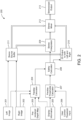
- FIG. 2 shows a system block diagram of a system or apparatus 200 for presenting stereoscopic content and ensuring that the parallax does not exceed safe values.
- a Parallax Calculator (204) determines the peaking parallax values for both hyperconvergence and hyperdivergence. The calculations are based either on a combination of Left (201) and Right (202) images, or from a Pre-Rendered Depth Map (203). It should be understood that the parallax calculator 204 does, in various implementations, determine minimum and maximum peaking disparity or depth, rather than parallax.
- the parallax calculator (204) determines the maximum parallax angle ⁇ MAX based on disparity or depth information supplied (as with pre-rendered depth map 203) or by analyzing the disparities between corresponding object images 201, 202. Likewise, the minimum parallax angle ⁇ MIN is found, too.
- a disparity histogram is used to assess maximum and minimum disparity.
- Display Information (205) which indicates the size of the display and viewing conditions (e.g., viewing distance, expected viewer interocular distance), is acquired. This can come from manual input, feedback from the display, a preset or any other source like eye tracking. Display information 205 may be used by parallax calculator 204, e.g., in conjunction with EQ. 2 or EQ. 4.
- the comfort threshold for viewing (206) is inputted by the user, a factory preset or another mechanism. This may be in terms of minimum and maximum disparities (physical or intrinsic), minimum and maximum apparent object distance (depth), and/or minimum and maximum parallax angle. Alternatively, this could be provided by example, e.g., a viewer might indicate when display of a test image becomes uncomfortable, and the noted threshold might be recorded.
- the comfort threshold can be set, for example, based on that recorded threshold (for example, disparity value).
- Examples include (i) setting the comfort threshold to the recorded threshold, (ii) setting the comfort threshold to the "depth" (for example, disparity) value one or two frames before the viewer indicated discomfort, or (iii) setting the comfort threshold to a value slightly "safer" than the recorded threshold, such as, for example, for a disparity value, setting the comfort threshold to 90% of the absolute value of the recorded disparity threshold.
- depth for example, disparity
- a Parallax Thresholds Calculator (207) takes the input from (205) and (206) and determines the minimum and maximum allowable parallax ( ⁇ MIN_THRESHOLD , ⁇ MAX_THRESHOLD ) for the content. It should be understood that the parallax thresholds calculator 207 does, in various implementations, determine minimum and maximum allowable disparity or depth, rather than parallax. Similarly, the A Safety Calculator (208) combines the threshold values (207) with the actual content peaking values (204) and determines whether action is required or not.
- the safety calculator 208 can be a comparator, triggering when ⁇ MAX > ⁇ MAX_THRESHOLD , or when ⁇ MIN ⁇ ⁇ MIN_THRESHOLD . More complex determinations typically use a processor and can consider duration, e.g., triggering when ⁇ MAX > ⁇ MAX_THRESHOLD for more than a predetermined amount of time, or when the integral over time of the angle by which ⁇ MAX exceeds ⁇ MAX_THRESHOLD exceeds a predetermined value. Such more complex determinations would allow the recognition that a viewer may be tolerant of a transient parallax excursion, but not care for the same extreme value if sustained.
- Further implementations also consider the portion of a display that is guilty of the parallax (or disparity or depth) excursion. For example, one or more implementations trigger a violation when a large object has a disparity above a given threshold.
- the size of the object that qualifies as "large” can be, for example, set by default, set by a user, or set to a certain percentage of the display size.
- Yet further implementations also consider the motion of an object in determining if a parallax violation has occurred. Moving objects often have higher parallax values and/or higher rates of change of parallax values. This aspect is captured, in various implementations, by considering both the absolute value of parallax and the rate of change of parallax. Such implementations base the decision of whether a parallax violation has occurred on at least these two factors of absolute value and rate of change. Such implementations will typically include another block (not shown in FIG. 2 ) to estimate the motion. The output of a motion estimation block, in various implementations, is provided as an input to the safety calculator 208.
- the safety calculator 208 When action is required by the safety calculator 208, it can take the form of a stereoscopic interpolation, provided by stereo interpolator (209), to constrain the parallax extremes to the thresholds (207), or a switch to 2D output (210) to prevent viewing excessive content.
- a stereoscopic interpolation provided by stereo interpolator (209), to constrain the parallax extremes to the thresholds (207), or a switch to 2D output (210) to prevent viewing excessive content.
- the interpolation is, in different implementations, either local or global. Certain implementations perform clipping of the absolute value of disparity at the maximum allowable value, which is a local operation that affects only the objects that violate the threshold. Other implementations interpolate the disparity of only the objects that violate the threshold, which is also a local operation. Other implementations, scale down the disparity of the entire image, which is a global operation affecting the disparity of the entire image (except perhaps objects having zero disparity).
- An option of the present disclosure is to provide a Stereo Source Buffer (211) and a Stereo Mixer (212) in order to provide smoother transitions between stereoscopic source content (201, 202; from 211) and either an interpolated stereoscopic output (from 209) or 2D output (from 210).
- double lines indicate stereoscopic signal paths (i.e., the outputs of modules 209-212), whereas non-stereoscopic signal paths (i.e., the outputs of sources 201, 202) are not so indicated.
- stereo source buffer 211 provides enough latency in a real-time signal path that safety calculator 208 is able to direct the necessary action before offending stereoscopic content is presented.
- the stereo source buffer 211 includes, in various implementations, sufficient memory or buffer length to allow the system 200 (i) to identify a violation of the safety threshold and/or the comfort threshold, (ii) to correct the violation, and (iii) to smooth the transition.
- stereo interpolator 209 obtains stereoscopic images from buffer 211 and computes a new stereoscopic image pair which is then provided to stereo mixer 212, and which stereo mixer 212 uses in preference to the unmodified stereoscopic stream from buffer 211.
- the new stereoscopic image pair represents the same scene, but presents it with parallax that is less extreme.
- the degree to which the extremeness of the parallax is reduced may be communicated by safety calculator 208, or in some embodiments may be a predetermined reduction.
- 2D output module 210 accepts stereoscopic content from buffer 211 and, when signaled by safety calculator 208, duplicates the left- or right-eye image of the stereoscopic image pair to replace the other-eye image. 2D output module 210 thus provides as output a 2D image pair, which is an image pair in which both images are the same. In this way, the parallax is completely squelched, resulting in a stereoscopic image that contains no disparity, that is, appears completely 2D. Stereo mixer 212 will use the 2D output 210, when provided, in preference to the unmodified stereoscopic stream from buffer 211.
- both stereo interpolator 209 and 2D output module 210 may be signaled by safety calculator 208, with stereo mixer 212 gradually fading among the sources 209-211 according to policy.
- modules 209-211 may produce their respective outputs continuously. Further, stereo mixer 212 can be commanded by safety calculator 208 to select among them.
- stereo source buffer 211 may be large enough to permit a gradual transition from the fully stereoscopic content as provided by left and right images 201, 202 to the parallax-limited content (whether interpolated stereoscopic images or 2D presentation).
- the buffer 211 holds ten frames. While the first frame is being shown, the safety calculator 208 determines that the tenth frame exceeds a limit. Then the stereo interpolator 209 is engaged for the second through tenth frames, to gradually introduce over those nine frames the appropriate correction to display the contents of the tenth frame without violating the limits.
- the buffer 211 still holds ten frames. However, the first frame in buffer 211 is flagged by safety calculator 208 as violating the safety or comfort threshold. Accordingly, a commensurate correction is provided (e.g., by stereo interpolator 209). No further frames in buffer 211 require any correction. Accordingly, the correction provided to the first frame is gradually eliminated over the succeeding frames. In such cases, stereo mixer 212 is configured to show images from stereo interpolator 209, when provided, in lieu of the corresponding images from stereo source buffer 211.
- stereo source buffer 211 again holds ten frames, and the 3D effect in the tenth frame is flagged by safety calculator 208 as violating the safety or comfort threshold.
- safety calculator 208 As a correction (modification), only 2D output 210 will be provided for the tenth frame.
- the transition is eased, however, by cross-fading the full stereoscopic images two through nine with the corresponding versions from 2D output 210.
- the crossfade is produced by mixer 212 by, for example, taking a partial contribution from the stereo source buffer 211 and a conjugate partial contribution from 2D output 210.
- the partial contribution from the stereo source buffer 211 starts at 90%, and the partial contribution from the 2D output 210 starts at 10%, so that the contributions total 100%.
- the contribution of the 2D output 210 increases frame by frame, and the contribution of the stereo source buffer 211 decreases in a corresponding manner frame by frame, so that the total is 100% for every frame.
- the result is that by the tenth frame, the stereoscopic output 213 is 100% 2D output 210.
- stereo mixer 212 may be configured to automatically begin a fade when images from 2D Output 210 become available.
- the use and degree of fade may be controlled by a control signal (not shown) from safety calculator 208.
- stereo mixer 212 provides the signal from stereo source buffer 211.
- Frame ten is flagged by safety calculator 208 as violating a safety or comfort threshold. Accordingly, stereo mixer 212 begins a fade to black over several frames, such as, for example, frames two through five. Stereo mixer 212 then switches to 2D output 210 as the source, but fades from black over frames six through nine. Frame ten is then shown following the fade-in, but in 2D only.
- the techniques may be selected or adjusted based on viewer preferences, a viewer profile, etc.
- the resulting combination of original stereoscopic source (201, 202; from 211), interpolated stereoscopic images (from 209), and/or 2D content (from 210) is then sent to the stereoscopic output (213) for viewing.
- safety calculator 208 can simply command 2D output module 210 to duplicate one of the left- and right-eye images into the other eye and provide that as stereoscopic output 213.
- Another option of the present disclosure is to have the process applied to the entirety of the stereoscopic content prior to viewing in order to provide higher quality interpolation, smoother transitions, or both.
- FIG. 3 shows process 300 for preventing excessive parallax viewing, which starts at 301 with display information 205 and user comfort threshold input 206 having been provided to threshold calculator 207, with the resulting thresholds and corresponding policy information 320 stored.
- Left- and right-eye images 201, 202 are available, in sequence as stereoscopic source 321.
- Stereoscopic source 321 may further comprise depth map 203, if supplied.
- the threshold information 320 is acquired.
- stereo source i.e., left image 201, right image 202
- parallax extremes are determined by parallax calculator 204 from stereoscopic source 321.
- safety calculator 208 determines whether the parallax extremes obtained at 204 are within the limits of the threshold information 320. If so, that is, if there is no safety violation, then at step 307 the images from the stereoscopic source are provided as output to be viewed. Otherwise, at step 306 a determination is made, also by safety calculator 208, as to whether the excessive parallax will be mitigated using stereoscopic interpolation or by forcing the output to be 2D.
- An example of determination 306 may be that for a slight violation of the parallax extremes in threshold information 320, stereoscopic interpolation is used, whereas for a more severe violation of the parallax extremes, 2D output is to be used. What constitutes slight vs. severe violations of the parallax extremes would be provided in threshold information 320 as a matter of policy.
- policies decisions use many different policy decisions in the process of determining whether to use interpolated stereoscopic output or a 2D output.
- Examples of policy decisions that are used in various implementations include one or more of the following: (i) if the parallax exceeds the comfort level by more than a threshold, then switch to 2D rather than interpolate, (ii) if objects exceed the comfort level on both the positive parallax and the negative parallax, then switch to 2D rather than interpolate, and/or (iii) if the parallax is above the comfort level and a high level of motion is detected, then switch to 2D rather than interpolate.
- the rationale for switching to 2D can be different for different implementations. Certain implementations switch to 2D for quality reasons, speed reasons, and/or complexity reasons. For example, when the parallax is excessive, the interpolation required to bring the parallax within the comfort level is frequently time consuming (speed reason) or requires considerable processing power and/or memory (complexity reasons). Further, such interpolation can degrade the quality of the images due to occlusions (quality reason).
- step 306 determines whether the determination is to use stereoscopic interpolation. If, at step 306, the determination is to use stereoscopic interpolation, then process 300 continues at step 308 where stereoscopic interpolator 209 processes the stereoscopic source (images 301, 302) to produce a stereoscopic interpolation that is output for viewing in step 309.
- a stereoscopic image pair having no disparity is produced by 2D output module 210, for example by copying a first eye image of the stereoscopic source (images 301, 302) into the other eye image, effectively creating a 2D image, but in a stereoscopic format.
- the 2D image in stereoscopic format is output for viewing.
- Steps 304-311 may be repeated (not shown in FIG. 3 ) for each stereoscopic image pair in stereo source 321. After the last stereoscopic image pair, or their interpolated or 2D replacements have been output by steps 307, 308, or 309, process 300 concludes at 312.
- step 306 will be absent and the sole provided remedy used (either steps 308/309 or 310/311).
- the operations 307, 309, and 311 are performed by, for example, the stereo mixer 212.
- the stereo mixer 212 also performs, in various implementations, a smoothing operation that is not shown in FIG. 3 (see, however, FIGS. 4-5 ). Smoothing is used, in this application, to refer, for example, to modifying a transition in depth (or in a depth indicator) so that the transition is not as large. This is frequently discussed as a filtering operation.
- the smoothing operation can be applied to, for example, the parallax, the depth, or the disparity. This smoothing is performed, in various implementations, in a spatial domain and/or a temporal domain.
- the stereo mixer 212 determines that smoothing is to be provided between (i) a transition from 3D (original or interpolated) to 2D, (ii) a transition from 2D to 3D (original or interpolated), (iii) a transition from original 3D to modified 3D, and/or (iv) a transition from modified 3D to original 3D.
- the modified 3D typically reflects, in various implementations, a modification that either lowered a depth indicator or increased a depth indicator for the associated portion of an image pair.
- Smoothing operations can take one or more of several forms. The following implementations illustrate a variety of smoothing operations:
- the smoothing operation extends temporally across a number of stereoscopic image pairs of a video sequence.
- Various implementations use more, or less, time or image pairs to perform smoothing operations.
- the speed with which the smoothing is performed, in terms of time or numbers of image pairs, can be determined, for example, by user preferences.
- the adjustment level in this context, is used to determine how strongly to modify a given image (or a portion of an image).
- An adjustment level can also be applied to spatial smoothing, to dictate the level of modification spatially. Further, an adjustment level can also be applied to increasing the absolute value of disparity, such as, for example, with a zero indicating no change and a one indicating a maximum change.
- the gradient can be used in a variety of implementations to guide the temporal smoothing process.
- the gradient is determined, for example, as the rate of change of an object's parallax (or depth, or disparity, for example) from image to image.
- Certain implementations also define the safety/comfort level based, in part at least, on the rate of change of parallax (for example).
- Various implementations temporally smooth an object's parallax (for example), sufficiently to bring the parallax down to an absolute level that is within a safety/comfort zone, and/or down to a level such that the rate of change of the parallax from the previous image to the current image is within a safety/comfort zone.
- the stereo mixer 212 determines that smoothing is to be provided within a given image because, for example, a local parallax (for example) modification was made. Due to the local modification, there may be a depth transition for a portion of the image that is uncomfortable for a viewer. The depth transition is often referred to as a depth transition for an object.
- Spatial smoothing operations can take one or more of several forms. The following implementations illustrate a variety of smoothing operations:
- the interpolation zone will surround an object that has a parallax (for example) that has already been modified. Additionally, the outer edge of the interpolation zone will be adjacent to an area that has not been modified. Both edges will, in certain implementations, be within the safety/comfort level, however. Depending on the severity of the modification that was performed on the object's parallax, there can be a variety of noticeable effects at the depth transition that will cause discomfort to a viewer and/or reduce perceived quality of the image.
- an adjustment level between, for example, zero and some positive integer.
- the adjustment level can be set, for example, to a value between zero (indicating that no adjustment is to be made) and five (indicating that a maximum adjustment is to be made).
- the adjustment level is combined with an interpolation zone, and the parallax (or depth or disparity) is adjusted from the level of the object toward the level of the area surrounding the interpolation zone. If the level is five, then the parallax (for example) is adjusted completely between the two values bordering the interpolation zone. If, however, the level is between zero and five, then the parallax (for example) is only partially adjusted from the value of the object toward the value of the area surrounding the interpolation zone. Accordingly, there is still a transition, but the transition is not as large as it would otherwise have been.
- smoothing is a form of interpolation, and typically uses interpolation to effect the parallax changes within the interpolation zone. Accordingly, in various implementations of FIG. 2 , the stereo mixer 212 instructs the stereo interpolator 209 to perform the desired smoothing. In such systems, the 2D output is also routed from the unit 210 to the stereo interpolator 209.
- Certain systems do not perform interpolation. Rather, certain implementations provide either original 3D or, if a comfort level is exceeded, 2D. Some of these implementations also provide smoothing between the transitions from 3D to 2D, and from 2D to 3D.
- FIG. 4 an implementation of a stereo mixer is provided that is able to perform smoothing.
- FIG. 4 includes a stereo mixer 412, which is an implementation of the stereo mixer 212 from FIG. 2 .
- the stereo mixer 412 includes a smoothing unit 420.
- the smoothing unit 420 includes, in various implementations, a filter or a processor for performing smoothing operations and algorithms.
- the smoothing unit 420 is coupled to an images storage unit 430 for storing images.
- the images stored in the images storage unit 430 include, for example, images in a stereoscopic image sequence that have been processed by the system 200 of FIG. 2 .
- the images stored in the images storage unit 430 can be images that occur previous in time to the current image(s) being processed. Additionally, or alternatively, the images stored in the images storage unit 430 can be later in time to the current image(s) being processed. In particular, certain implementations that operate iteratively can access images that occur previous in time or later in time to the current image(s) being processed.
- the smoothing unit 420 is also coupled to a rules storage unit 440.
- the rules storage unit 440 stores rules, and a rule can include any parameter used in a smoothing process performed by the smoothing unit 420.
- Such parameters include, for example, parameters related to temporal smoothing, parameters related to spatial smoothing, parameters identifying a smoothing zone, parameters identifying a filter or providing filter parameters. Various of these parameters are further discussed below.
- the smoothing unit 420 is also coupled to the stereo interpolator 209, the 2D output module 210, and the stereo source buffer 211 described in the discussion of FIG. 2 .
- the smoothing unit 420 interacts with the stereo interpolator 209, the 2D output module 210, and the stereo source buffer 211, in a similar manner discussed for the stereo mixer 212 of FIG. 2 .
- the smoothing unit 420 is also coupled to the stereoscopic output 213.
- the smoothing unit 420 interacts with the stereoscopic output 213, in a similar manner discussed for the stereo mixer 212 of FIG. 2 .
- the smoothing unit 420 is operable to perform a variety of smoothing operations. Various of these smoothing operations are described below with respect to FIG. 5 and the additional implementations of related to FIG. 5 .
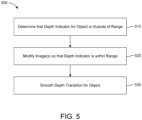
- a process 500 is provided for smoothing a depth transition. It is understood that a depth transition also refers to and includes a disparity transition. A depth transition can occur, for example, as a spatial transition within a picture, or as a temporal transition across multiple pictures.
- An example of a spatial depth transition includes a transition from an area of, for example, high disparity to a separate area in the same image that has low disparity.
- a spatial depth transition is, in different circumstances, a gradual transition, or an abrupt transition.
- An example of a temporal depth transition includes a transition from a first image in a sequence to a subsequent image in the sequence. There are frequently multiple depth transitions that occur in the transition from a first image to a subsequent image. Depth transitions are typically tracked for a specific object that occurs in both the first image and the subsequent image. Thus, for a given object that occurs in both the first image and the subsequent image, the object will have a respective depth in each of the first image and the subsequent image.
- the temporal depth transition for the object refers to the change in depth for the object from the first image to the subsequent image.
- the temporal depth transition can be, for example, flat if the depth for the object is the same in both the first image and the subsequent image, gradual if the depth changes by a small amount from the first image to the subsequent image, or abrupt if the depth change by a substantial amount from the first image to the subsequent image.
- the process 500 includes determining that a depth indicator for an object is outside of a range (510).
- the operation 510 includes determining that a depth indicator for an object in a stereoscopic image pair of a video sequence is outside of a target range.
- a depth indicator is an indicator of depth, or of disparity or parallax.
- Examples of a depth indicator include a value of depth or disparity or parallax, or a range of depth or disparity or parallax.
- a value or a range is indicated, in various implementations, by a number or range of numbers, by a color or range of colors, by a size or range of sizes (such as, for example, by bars in a histogram).
- the operation 510 is performed, for example, by the operation 305 that determines that a parallax extreme has been violated.
- the operation 510 is performed, for example, by the safety calculator 208.
- the process 500 includes modifying one or more images so that the depth indicator is within the range (520).
- the operation 520 includes modifying one or more images of a stereoscopic image pair so that the depth indicator for an object is within a target range.
- the operation 520 is performed, for example, by the operation 308 that interpolates a stereoscopic source, or by the operation 310 that duplicates one eye image in the other eye.
- the operation 520 is performed, for example, by the stereo interpolator 209 of FIG. 2 (performing, for example, the operation 308) or by the 2D output 210 of FIG. 2 (performing, for example, the operation 310).
- the operation 308 modifies the image by interpolating.
- the operation 310 modifies the image by replacing the image with a 2D version, that is, by replacing one image of a stereoscopic image pair with a copy of the other image of the stereoscopic image pair.
- the process 500 includes an optional step of smoothing a depth transition for the object (530).
- the operation 530 includes smoothing a depth transition between the object and another portion of the video sequence.
- the operation 530 is performed, for example, by the stereo mixer 212 and/or the stereo mixer 412.
- Various implementations perform switching by using, at least in part, cross-fades, fade-ins, fade-outs, fades-to-black, and fades-from-black.
- a scene change involves a large depth transition, and a fade-to-black at the end of the first scene, followed by a fade-in at the beginning of the new scene, are performed to avoid the large depth transition.
- the stereo mixer 212 switches between different inputs, including 2D, original 3D, and modified 3D.
- stereo mixers are commonly implemented with a stereo switcher.
- Typical stereo switchers are also capable of performing the cross-fades, fade-ins, fade-outs, fade-to-blacks, and fade-from-blacks, discussed above.
- Smoothing is facilitated in many implementations by using, for example, a large buffer in the stereo mixer 212.
- a large buffer provides time for the stereo mixer 212 to identify a depth violation in a particular image, to address that depth violation in the particular image, and to perform smoothing.
- the smoothing is performed, in different implementations, on the images preceding the particular image, on the images succeeding the particular image, and/or on the particular image.
- Various implementations modify stereoscopic image pairs, when a safety or comfort threshold is violated for a pair, by replacing the offending stereoscopic image pairs with corresponding 2D image pairs.
- Several such implementations can produce a video sequence that includes (i) one or more stereoscopic image pairs having non-zero disparity and for which a depth indicator does not violate a safety or comfort threshold for the entire image pair, and (ii) one or more 2D image pairs.
- Such implementations can provide a useful approach to complying with a requirement to avoid excessive 3D.
- Several such implementations further provide optional smoothing features.
- the video sequence that is modified and/or smoothed is provided for one or more of (i) storage, (ii) transmission, or (iii) presentation.
- the stereoscopic output 213 can be presented on any of a variety of display devices.
- display devices include, for example, a television, a computer display, a tablet, or a cell phone.
- FIGS. 2-5 may be implemented in various forms of hardware, software, or combinations thereof. Typically, these elements are implemented in a combination of hardware and software on one or more appropriately programmed general-purpose devices, which may include a processor, memory, and input/output interfaces.
- general-purpose devices which may include a processor, memory, and input/output interfaces.
- the phrase "coupled" is defined to mean directly connected to or indirectly connected through one or more intermediate components. Such intermediate components may include both hardware and software based components.
- processors may be provided through the use of dedicated hardware as well as hardware capable of executing software in association with appropriate software.
- the functions may be provided by a single dedicated processor, by a single shared processor, or by a plurality of individual processors, some of which may be shared.
- explicit use of the term "processor” or “controller” should not be construed to refer exclusively to hardware capable of executing software, and may implicitly include, without limitation, digital signal processor ("DSP”) hardware, read only memory (“ROM”) for storing software, random access memory (“RAM”), and nonvolatile storage.
- DSP digital signal processor
- ROM read only memory
- RAM random access memory
- nonvolatile storage nonvolatile storage
- any switches shown in the figures are conceptual only. Their function may be carried out through the operation of program logic, through dedicated logic, through the interaction of program control and dedicated logic, or even manually, the particular technique being selectable by the implementer as more specifically understood from the context.
- FIGS. 2 and 4 This application provides multiple figures, including the block diagrams of FIGS. 2 and 4 , and the flow diagrams of FIGS. 3 and 5 . Each of these figures provides disclosure for a variety of implementations.
- Various implementations attempt to prevent excessive parallax, depth, or disparity from being presented to a viewer.
- Various implementations (i) interpolate 3D content, (ii) replace 3D content with 2D content, and/or (iii) smooth content.
- the content that is smoothed can be 2D or 3D content, and various techniques are discussed for performing the smoothing operations.
- the appearances of the phrase “in one embodiment” or “in an embodiment” or “in one implementation” or “in an implementation”, as well any other variations, appearing in various places throughout the specification are not necessarily all referring to the same embodiment.
- Determining the information may include one or more of, for example, estimating the information, calculating the information, predicting the information, or retrieving the information from memory.
- such phrasing is intended to encompass the selection of the first listed option (A) only, or the selection of the second listed option (B) only, or the selection of the third listed option (C) only, or the selection of the first and the second listed options (A and B) only, or the selection of the first and third listed options (A and C) only, or the selection of the second and third listed options (B and C) only, or the selection of all three options (A and B and C).
- This may be extended, as readily apparent by one of ordinary skill in this and related arts, for as many items listed.
- a processor such as, for example, a post-processor or a pre-processor.
- the processing devices discussed in this application do, in various implementations, include multiple processors (sub-processors) that are collectively configured to perform, for example, a process, a function, or an operation.
- the smoothing unit 420 is, in various implementations, composed of multiple sub-processors that are collectively configured to perform the operations of the smoothing unit 420.
- the implementations described herein may be implemented in, for example, a method or a process, an apparatus, a software program, a data stream, or a signal. Even if only discussed in the context of a single form of implementation (for example, discussed only as a method), the implementation of features discussed may also be implemented in other forms (for example, an apparatus or program).
- An apparatus may be implemented in, for example, appropriate hardware, software, and firmware.
- the methods may be implemented in, for example, an apparatus such as, for example, a processor, which refers to processing devices in general, including, for example, a computer, a microprocessor, an integrated circuit, or a programmable logic device. Processors also include communication devices, such as, for example, computers, cell phones, tablets, portable/personal digital assistants ("PDAs”), and other devices that facilitate communication of information between end-users.
- PDAs portable/personal digital assistants
- Implementations of the various processes and features described herein may be embodied in a variety of different equipment or applications.
- equipment include an encoder, a decoder, a post-processor, a pre-processor, a video coder, a video decoder, a video codec, a web server, a television, a set-top box, a router, a gateway, a modem, a laptop, a personal computer, a tablet, a cell phone, a PDA, and other communication devices.
- the equipment may be mobile and even installed in a mobile vehicle.
- the methods may be implemented by instructions being performed by a processor, and such instructions (and/or data values produced by an implementation) may be stored on a processor-readable medium such as, for example, an integrated circuit, a software carrier or other storage device such as, for example, a hard disk, a compact diskette (“CD"), an optical disc (such as, for example, a DVD, often referred to as a digital versatile disc or a digital video disc), a random access memory (“RAM”), or a read-only memory (“ROM”).
- the instructions may form an application program tangibly embodied on a processor-readable medium. Instructions may be, for example, in hardware, firmware, software, or a combination.
- a processor may be characterized, therefore, as, for example, both a device configured to carry out a process and a device that includes a processor-readable medium (such as a storage device) having instructions for carrying out a process. Further, a processor-readable medium may store, in addition to or in lieu of instructions, data values produced by an implementation.
Landscapes
- Engineering & Computer Science (AREA)
- Multimedia (AREA)
- Signal Processing (AREA)
- Computer Vision & Pattern Recognition (AREA)
- Physics & Mathematics (AREA)
- General Physics & Mathematics (AREA)
- Theoretical Computer Science (AREA)
- Testing, Inspecting, Measuring Of Stereoscopic Televisions And Televisions (AREA)
- Processing Or Creating Images (AREA)
Claims (2)
- Procédé comprenant :- le stockage dans une mémoire tampon d'une pluralité de paires d'images stéréoscopiques correspondant à des trames consécutives d'une séquence vidéo ;- la détermination d'un indicateur de profondeur pour un objet de la paire d'images stéréoscopiques stockée correspondant à la dernière trame comme étant supérieur à une première valeur ou inférieur à une deuxième valeur inférieure à la première valeur ; et- en réponse à la détermination, la modification d'une ou de plusieurs images de ladite paire d'images stéréoscopiques stockée, où la modification d'une ou de plusieurs images de ladite paire d'images stéréoscopiques stockée comprend le remplacement de ladite paire d'images stéréoscopiques stockée correspondant à la dernière trame par une paire d'images 2D qui inclut l'objet, ladite paire d'images 2D étant obtenue par duplication de l'image vue par l'oeil droit ou de l'image vue par l'oeil gauche de la paire d'images stéréoscopiques ;- le fondu enchaîné des paires d'images stéréoscopiques stockées correspondant aux trames précédant ladite dernière trame, et de leurs paires d'images 2D correspondantes, une dite paire d'images correspondante d'une trame étant obtenue par duplication de l'image vue par l'oeil droit ou de l'image vue par l'oeil gauche de la paire d'images stéréoscopiques de ladite trame, en prenant, pour chacune desdites trames précédentes, une contribution partielle de sa paire d'images stéréoscopiques stockée et une contribution partielle conjuguée d'une paire d'images 2D correspondante, la contribution partielle de ladite paire d'images stéréoscopiques stockée diminuant trame par trame et la contribution partielle conjuguée de la paire d'images 2D correspondante augmentant d'une manière correspondante trame par trame de la trame précédente la plus éloignée à la plus proche.
- Appareil comprenant :- une mémoire tampon de source stéréo (211) configurée pour stocker une pluralité de paires d'images stéréoscopiques correspondant à des trames consécutives d'une séquence vidéo ;- un calculateur de sécurité (208) configuré pour déterminer qu'un indicateur de profondeur pour un objet de la paire d'images stéréoscopiques de ladite pluralité de paires d'images stéréoscopiques correspondant à la dernière trame est supérieur à une première valeur ou inférieur à une deuxième valeur inférieure à la première valeur ; et- un module de sortie 2D (210) configuré pour, en réponse à la détermination, modifier une ou plusieurs images de ladite paire d'images stéréoscopiques en remplaçant ladite paire d'images stéréoscopiques correspondant à la dernière trame par une paire d'images 2D qui inclut l'objet, ladite paire d'images 2D étant obtenue par duplication de l'image vue par l'oeil droit ou de l'image vue par l'oeil gauche de la paire d'images stéréoscopiques ; et- un mélangeur stéréo (212) configuré pour effectuer un fondu enchaîné des paires d'images stéréoscopiques stockées correspondant aux trames précédant ladite dernière trame, et de leurs paires d'images 2D correspondantes, en prenant, pour chacune desdites trames précédentes, une contribution partielle de sa paire d'images stéréoscopiques stockée et une contribution partielle conjuguée de sa paire d'images 2D correspondante, une dite paire d'images correspondante étant obtenue par duplication de l'image vue par l'oeil droit ou de l'image vue par l'oeil gauche de la paire d'images stéréoscopiques de ladite trame, la contribution partielle de ladite paire d'images stéréoscopiques stockée diminuant trame par trame et la contribution partielle conjuguée de la paire d'images 2D correspondante augmentant d'une manière correspondante trame par trame de la trame précédente la plus éloignée à la plus proche.
Applications Claiming Priority (4)
| Application Number | Priority Date | Filing Date | Title |
|---|---|---|---|
| US201261583105P | 2012-01-04 | 2012-01-04 | |
| US201261583462P | 2012-01-05 | 2012-01-05 | |
| US201261584123P | 2012-01-06 | 2012-01-06 | |
| PCT/IB2012/002927 WO2013102790A2 (fr) | 2012-01-04 | 2012-12-20 | Traitement de séquences d'images 3d |
Publications (2)
| Publication Number | Publication Date |
|---|---|
| EP2801198A2 EP2801198A2 (fr) | 2014-11-12 |
| EP2801198B1 true EP2801198B1 (fr) | 2023-10-11 |
Family
ID=47739399
Family Applications (1)
| Application Number | Title | Priority Date | Filing Date |
|---|---|---|---|
| EP12824849.9A Active EP2801198B1 (fr) | 2012-01-04 | 2012-12-20 | Traitement de séquences d'images 3d |
Country Status (5)
| Country | Link |
|---|---|
| US (1) | US9313475B2 (fr) |
| EP (1) | EP2801198B1 (fr) |
| JP (1) | JP6215228B2 (fr) |
| KR (1) | KR102131745B1 (fr) |
| WO (1) | WO2013102790A2 (fr) |
Families Citing this family (10)
| Publication number | Priority date | Publication date | Assignee | Title |
|---|---|---|---|---|
| US9736467B2 (en) * | 2013-08-05 | 2017-08-15 | Samsung Display Co., Ltd. | Apparatus and method for adjusting stereoscopic images in response to head roll |
| WO2015100490A1 (fr) * | 2014-01-06 | 2015-07-09 | Sensio Technologies Inc. | Reconfiguration et distribution de contenu stereoscopique dans une configuration convenant pour un environnement de visualisation a distance |
| US10935788B2 (en) * | 2014-01-24 | 2021-03-02 | Nvidia Corporation | Hybrid virtual 3D rendering approach to stereovision |
| US10230932B2 (en) * | 2014-02-13 | 2019-03-12 | Autodesk, Inc. | Techniques for animating transitions between non-stereoscopic and stereoscopic imaging |
| US11218682B2 (en) * | 2015-01-21 | 2022-01-04 | Nevermind Capital Llc | Methods and apparatus for processing and or encoding images with negative parallax |
| CN106851246B (zh) | 2017-02-06 | 2019-08-23 | 京东方科技集团股份有限公司 | 用于确定三维图像或视频的视觉疲劳度的方法和设备 |
| EP3596705A4 (fr) | 2017-03-17 | 2020-01-22 | Magic Leap, Inc. | Système de réalité mixte à déformation de contenu virtuel couleur et procédé de génération de contenu virtuel l'utilisant |
| CN108496201A (zh) * | 2017-09-27 | 2018-09-04 | 深圳市大疆创新科技有限公司 | 图像处理方法和设备 |
| CN116483200A (zh) * | 2018-07-23 | 2023-07-25 | 奇跃公司 | 具有虚拟内容翘曲的混合现实系统和使用该系统生成虚拟内容的方法 |
| KR102479120B1 (ko) * | 2020-12-18 | 2022-12-16 | 한국공학대학교산학협력단 | 가변 초점 방식의 3d 텐서 기반 3차원 영상 획득 방법 및 장치 |
Citations (6)
| Publication number | Priority date | Publication date | Assignee | Title |
|---|---|---|---|---|
| EP0963122A2 (fr) * | 1998-06-04 | 1999-12-08 | Olympus Optical Co., Ltd. | Système de production d'images stéréoscopiques |
| JP2005167310A (ja) * | 2003-11-28 | 2005-06-23 | Sharp Corp | 撮影装置 |
| US20050219239A1 (en) * | 2004-03-31 | 2005-10-06 | Sanyo Electric Co., Ltd. | Method and apparatus for processing three-dimensional images |
| US20070236493A1 (en) * | 2003-05-27 | 2007-10-11 | Keiji Horiuchi | Image Display Apparatus and Program |
| US20080112616A1 (en) * | 2006-11-14 | 2008-05-15 | Samsung Electronics Co., Ltd. | Method for adjusting disparity in three-dimensional image and three-dimensional imaging device thereof |
| WO2011114567A1 (fr) * | 2010-03-18 | 2011-09-22 | 富士フイルム株式会社 | Dispositif d'affichage 3d et dispositif d'imagerie 3d, procédé de détermination de l'œil directeur et programme de détermination de l'œil directeur utilisant ledit procédé, et support d'enregistrement |
Family Cites Families (45)
| Publication number | Priority date | Publication date | Assignee | Title |
|---|---|---|---|---|
| JPH0787598B2 (ja) * | 1991-06-06 | 1995-09-20 | 株式会社エイ・ティ・アール視聴覚機構研究所 | 視差補正装置 |
| JPH0954376A (ja) | 1995-06-09 | 1997-02-25 | Pioneer Electron Corp | 立体表示装置 |
| JPH099300A (ja) * | 1995-06-26 | 1997-01-10 | Matsushita Electric Ind Co Ltd | 立体表示装置 |
| JP3397602B2 (ja) | 1996-11-11 | 2003-04-21 | 富士通株式会社 | 画像表示装置及び方法 |
| GB0125774D0 (en) | 2001-10-26 | 2001-12-19 | Cableform Ltd | Method and apparatus for image matching |
| JP3938122B2 (ja) * | 2002-09-20 | 2007-06-27 | 日本電信電話株式会社 | 擬似3次元画像生成装置および生成方法並びにそのためのプログラムおよび記録媒体 |
| US7636088B2 (en) * | 2003-04-17 | 2009-12-22 | Sharp Kabushiki Kaisha | 3-Dimensional image creation device, 3-dimensional image reproduction device, 3-dimensional image processing device, 3-dimensional image processing program, and recording medium containing the program |
| WO2005009052A1 (fr) | 2003-07-16 | 2005-01-27 | Koninklijke Philips Electronics N.V. | Affichage autostereoscopique a detection des mouvements de la tete |
| KR20050012328A (ko) | 2003-07-25 | 2005-02-02 | 엘지전자 주식회사 | 고밀도 광디스크의 프레젠테이션 그래픽 데이터 관리 및재생방법과 그에 따른 고밀도 광디스크 |
| US8094927B2 (en) | 2004-02-27 | 2012-01-10 | Eastman Kodak Company | Stereoscopic display system with flexible rendering of disparity map according to the stereoscopic fusing capability of the observer |
| JP2006178900A (ja) | 2004-12-24 | 2006-07-06 | Hitachi Displays Ltd | 立体画像生成装置 |
| US8384763B2 (en) | 2005-07-26 | 2013-02-26 | Her Majesty the Queen in right of Canada as represented by the Minster of Industry, Through the Communications Research Centre Canada | Generating a depth map from a two-dimensional source image for stereoscopic and multiview imaging |
| CN101356831B (zh) | 2005-11-30 | 2010-09-01 | 意大利电信股份公司 | 用于确定立体视觉中的分散视差场的方法 |
| CN101322418B (zh) | 2005-12-02 | 2010-09-01 | 皇家飞利浦电子股份有限公司 | 图像信号的深度相关的滤波 |
| JP2008021163A (ja) * | 2006-07-13 | 2008-01-31 | Matsushita Electric Ind Co Ltd | 画像処理装置 |
| US8330801B2 (en) * | 2006-12-22 | 2012-12-11 | Qualcomm Incorporated | Complexity-adaptive 2D-to-3D video sequence conversion |
| US7683962B2 (en) | 2007-03-09 | 2010-03-23 | Eastman Kodak Company | Camera using multiple lenses and image sensors in a rangefinder configuration to provide a range map |
| KR101345303B1 (ko) | 2007-03-29 | 2013-12-27 | 삼성전자주식회사 | 스테레오 또는 다시점 영상의 입체감 조정 방법 및 장치 |
| WO2009020277A1 (fr) * | 2007-08-06 | 2009-02-12 | Samsung Electronics Co., Ltd. | Procédé et appareil pour reproduire une image stéréoscopique par utilisation d'une commande de profondeur |
| US8300086B2 (en) | 2007-12-20 | 2012-10-30 | Nokia Corporation | Image processing for supporting a stereoscopic presentation |
| JP4695664B2 (ja) * | 2008-03-26 | 2011-06-08 | 富士フイルム株式会社 | 立体動画像処理装置および方法並びにプログラム |
| JP4608563B2 (ja) | 2008-03-26 | 2011-01-12 | 富士フイルム株式会社 | 立体画像表示装置および方法並びにプログラム |
| US8238612B2 (en) | 2008-05-06 | 2012-08-07 | Honeywell International Inc. | Method and apparatus for vision based motion determination |
| US20090282429A1 (en) | 2008-05-07 | 2009-11-12 | Sony Ericsson Mobile Communications Ab | Viewer tracking for displaying three dimensional views |
| US8787654B2 (en) * | 2008-05-12 | 2014-07-22 | Thomson Licensing | System and method for measuring potential eyestrain of stereoscopic motion pictures |
| EP2387243A4 (fr) * | 2009-01-12 | 2012-12-26 | Lg Electronics Inc | Procédé de traitement de signal vidéo et appareil utilisant des informations de profondeur |
| JP5434231B2 (ja) * | 2009-04-24 | 2014-03-05 | ソニー株式会社 | 画像情報処理装置、撮像装置、画像情報処理方法およびプログラム |
| GB2471137B (en) * | 2009-06-19 | 2011-11-30 | Sony Comp Entertainment Europe | 3D image processing method and apparatus |
| US9380292B2 (en) * | 2009-07-31 | 2016-06-28 | 3Dmedia Corporation | Methods, systems, and computer-readable storage media for generating three-dimensional (3D) images of a scene |
| US20110032341A1 (en) | 2009-08-04 | 2011-02-10 | Ignatov Artem Konstantinovich | Method and system to transform stereo content |
| KR101699920B1 (ko) * | 2009-10-07 | 2017-01-25 | 삼성전자주식회사 | 깊이 조절 방법 및 장치 |
| US8798160B2 (en) | 2009-11-06 | 2014-08-05 | Samsung Electronics Co., Ltd. | Method and apparatus for adjusting parallax in three-dimensional video |
| JP2011124941A (ja) * | 2009-12-14 | 2011-06-23 | Mitsubishi Electric Corp | 3次元映像生成装置及び3次元映像生成方法 |
| WO2011081646A1 (fr) | 2009-12-15 | 2011-07-07 | Thomson Licensing | Indications de qualité et de disparité/profondeur d'images stéréo |
| JP5505881B2 (ja) | 2010-02-02 | 2014-05-28 | 学校法人早稲田大学 | 立体映像制作装置およびプログラム |
| JP5565001B2 (ja) * | 2010-03-04 | 2014-08-06 | 株式会社Jvcケンウッド | 立体映像撮像装置、立体映像処理装置および立体映像撮像方法 |
| JP5292364B2 (ja) * | 2010-07-07 | 2013-09-18 | 株式会社ソニー・コンピュータエンタテインメント | 画像処理装置および画像処理方法 |
| AU2011283658B2 (en) | 2010-07-30 | 2016-01-28 | Rtc Industries, Inc | Product securement and management system |
| US9565415B2 (en) * | 2010-09-14 | 2017-02-07 | Thomson Licensing | Method of presenting three-dimensional content with disparity adjustments |
| JP5150698B2 (ja) * | 2010-09-30 | 2013-02-20 | 株式会社東芝 | デプス補正装置及び方法 |
| EP2633688B1 (fr) | 2010-10-29 | 2018-05-02 | Thomson Licensing DTV | Procédé pour générer des images en trois dimensions en incrustant un objet graphique dans l'image et dispositif d'affichage associé |
| CN102696054B (zh) * | 2010-11-10 | 2016-08-03 | 松下知识产权经营株式会社 | 进深信息生成装置、进深信息生成方法及立体图像变换装置 |
| JP2012178688A (ja) * | 2011-02-25 | 2012-09-13 | Olympus Corp | 立体画像撮影装置 |
| JP5178876B2 (ja) * | 2011-04-27 | 2013-04-10 | 株式会社東芝 | 立体映像表示装置及び立体映像表示方法 |
| WO2012156489A1 (fr) | 2011-05-19 | 2012-11-22 | Thomson Licensing | Conversion automatique d'une image stéréoscopique pour permettre un affichage simultanément stéréoscopique et monoscopique de ladite image |
-
2012
- 2012-12-20 JP JP2014550766A patent/JP6215228B2/ja active Active
- 2012-12-20 KR KR1020147018241A patent/KR102131745B1/ko active IP Right Grant
- 2012-12-20 WO PCT/IB2012/002927 patent/WO2013102790A2/fr active Application Filing
- 2012-12-20 EP EP12824849.9A patent/EP2801198B1/fr active Active
- 2012-12-20 US US14/368,558 patent/US9313475B2/en active Active
Patent Citations (7)
| Publication number | Priority date | Publication date | Assignee | Title |
|---|---|---|---|---|
| EP0963122A2 (fr) * | 1998-06-04 | 1999-12-08 | Olympus Optical Co., Ltd. | Système de production d'images stéréoscopiques |
| US20070236493A1 (en) * | 2003-05-27 | 2007-10-11 | Keiji Horiuchi | Image Display Apparatus and Program |
| JP2005167310A (ja) * | 2003-11-28 | 2005-06-23 | Sharp Corp | 撮影装置 |
| US20050219239A1 (en) * | 2004-03-31 | 2005-10-06 | Sanyo Electric Co., Ltd. | Method and apparatus for processing three-dimensional images |
| US20080112616A1 (en) * | 2006-11-14 | 2008-05-15 | Samsung Electronics Co., Ltd. | Method for adjusting disparity in three-dimensional image and three-dimensional imaging device thereof |
| WO2011114567A1 (fr) * | 2010-03-18 | 2011-09-22 | 富士フイルム株式会社 | Dispositif d'affichage 3d et dispositif d'imagerie 3d, procédé de détermination de l'œil directeur et programme de détermination de l'œil directeur utilisant ledit procédé, et support d'enregistrement |
| US20120320047A1 (en) * | 2010-03-18 | 2012-12-20 | Fujifilm Corporation | Stereoscopic display apparatus and stereoscopic shooting apparatus, dominant eye judging method and dominant eye judging program for use therein, and recording medium |
Also Published As
| Publication number | Publication date |
|---|---|
| US9313475B2 (en) | 2016-04-12 |
| WO2013102790A3 (fr) | 2013-12-27 |
| KR20140119692A (ko) | 2014-10-10 |
| US20150071525A1 (en) | 2015-03-12 |
| CN104067612A (zh) | 2014-09-24 |
| WO2013102790A9 (fr) | 2014-07-31 |
| EP2801198A2 (fr) | 2014-11-12 |
| JP2015508947A (ja) | 2015-03-23 |
| JP6215228B2 (ja) | 2017-10-18 |
| WO2013102790A2 (fr) | 2013-07-11 |
| KR102131745B1 (ko) | 2020-07-08 |
Similar Documents
| Publication | Publication Date | Title |
|---|---|---|
| EP2801198B1 (fr) | Traitement de séquences d'images 3d | |
| US9036006B2 (en) | Method and system for processing an input three dimensional video signal | |
| KR101310212B1 (ko) | 입체 상의 3d 객체를 상대적인 깊이로 삽입하는 방법 | |
| US8798160B2 (en) | Method and apparatus for adjusting parallax in three-dimensional video | |
| US10165249B2 (en) | Method for smoothing transitions between scenes of a stereo film and controlling or regulating a plurality of 3D cameras | |
| CN102598683A (zh) | 立体影像制作装置以及立体影像制作方法 | |
| US20120113093A1 (en) | Modification of perceived depth by stereo image synthesis | |
| RU2640645C2 (ru) | Система для генерирования изображения промежуточного вида | |
| US20130187907A1 (en) | Image processing apparatus, image processing method, and program | |
| CN108174177B (zh) | 立体校正装置 | |
| US20120121164A1 (en) | Image processing apparatus and control method therefor | |
| US10230932B2 (en) | Techniques for animating transitions between non-stereoscopic and stereoscopic imaging | |
| KR20110050364A (ko) | 3차원 비디오의 깊이감 조절 방법 및 그 장치 | |
| CN104067612B (zh) | 3d图像序列的处理 | |
| JP2013026943A (ja) | 立体画像処理装置および立体画像処理方法 | |
| JP2014525186A (ja) | ステレオフィルムのシーン間の遷移を滑らかにし、複数の3dカメラを制御または調整する方法 |
Legal Events
| Date | Code | Title | Description |
|---|---|---|---|
| PUAI | Public reference made under article 153(3) epc to a published international application that has entered the european phase |
Free format text: ORIGINAL CODE: 0009012 |
|
| 17P | Request for examination filed |
Effective date: 20140718 |
|
| AK | Designated contracting states |
Kind code of ref document: A2 Designated state(s): AL AT BE BG CH CY CZ DE DK EE ES FI FR GB GR HR HU IE IS IT LI LT LU LV MC MK MT NL NO PL PT RO RS SE SI SK SM TR |
|
| DAX | Request for extension of the european patent (deleted) | ||
| RAP1 | Party data changed (applicant data changed or rights of an application transferred) |
Owner name: THOMSON LICENSING DTV |
|
| RAP1 | Party data changed (applicant data changed or rights of an application transferred) |
Owner name: INTERDIGITAL MADISON PATENT HOLDINGS |
|
| REG | Reference to a national code |
Ref country code: DE Ref legal event code: R079 Ref document number: 602012080183 Country of ref document: DE Free format text: PREVIOUS MAIN CLASS: H04N0013000000 Ipc: H04N0013144000 Ref country code: DE Ref legal event code: R079 Free format text: PREVIOUS MAIN CLASS: H04N0013000000 Ipc: H04N0013144000 |
|
| STAA | Information on the status of an ep patent application or granted ep patent |
Free format text: STATUS: EXAMINATION IS IN PROGRESS |
|
| PUAG | Search results despatched under rule 164(2) epc together with communication from examining division |
Free format text: ORIGINAL CODE: 0009017 |
|
| 17Q | First examination report despatched |
Effective date: 20190905 |
|
| B565 | Issuance of search results under rule 164(2) epc |
Effective date: 20190905 |
|
| RIC1 | Information provided on ipc code assigned before grant |
Ipc: H04N 13/144 20180101AFI20190902BHEP Ipc: H04N 13/128 20180101ALI20190902BHEP Ipc: G06T 7/593 20170101ALI20190902BHEP |
|
| STAA | Information on the status of an ep patent application or granted ep patent |
Free format text: STATUS: EXAMINATION IS IN PROGRESS |
|
| STAA | Information on the status of an ep patent application or granted ep patent |
Free format text: STATUS: EXAMINATION IS IN PROGRESS |
|
| RAP3 | Party data changed (applicant data changed or rights of an application transferred) |
Owner name: INTERDIGITAL MADISON PATENT HOLDINGS, SAS |
|
| GRAP | Despatch of communication of intention to grant a patent |
Free format text: ORIGINAL CODE: EPIDOSNIGR1 |
|
| STAA | Information on the status of an ep patent application or granted ep patent |
Free format text: STATUS: GRANT OF PATENT IS INTENDED |
|
| INTG | Intention to grant announced |
Effective date: 20230208 |
|
| GRAJ | Information related to disapproval of communication of intention to grant by the applicant or resumption of examination proceedings by the epo deleted |
Free format text: ORIGINAL CODE: EPIDOSDIGR1 |
|
| STAA | Information on the status of an ep patent application or granted ep patent |
Free format text: STATUS: EXAMINATION IS IN PROGRESS |
|
| INTC | Intention to grant announced (deleted) | ||
| GRAP | Despatch of communication of intention to grant a patent |
Free format text: ORIGINAL CODE: EPIDOSNIGR1 |
|
| STAA | Information on the status of an ep patent application or granted ep patent |
Free format text: STATUS: GRANT OF PATENT IS INTENDED |
|
| INTG | Intention to grant announced |
Effective date: 20230525 |
|
| P01 | Opt-out of the competence of the unified patent court (upc) registered |
Effective date: 20230514 |
|
| GRAS | Grant fee paid |
Free format text: ORIGINAL CODE: EPIDOSNIGR3 |
|
| GRAA | (expected) grant |
Free format text: ORIGINAL CODE: 0009210 |
|
| STAA | Information on the status of an ep patent application or granted ep patent |
Free format text: STATUS: THE PATENT HAS BEEN GRANTED |
|
| AK | Designated contracting states |
Kind code of ref document: B1 Designated state(s): AL AT BE BG CH CY CZ DE DK EE ES FI FR GB GR HR HU IE IS IT LI LT LU LV MC MK MT NL NO PL PT RO RS SE SI SK SM TR |
|
| REG | Reference to a national code |
Ref country code: GB Ref legal event code: FG4D |
|
| REG | Reference to a national code |
Ref country code: CH Ref legal event code: EP |
|
| REG | Reference to a national code |
Ref country code: DE Ref legal event code: R096 Ref document number: 602012080183 Country of ref document: DE |
|
| REG | Reference to a national code |
Ref country code: IE Ref legal event code: FG4D |
|
| REG | Reference to a national code |
Ref country code: NL Ref legal event code: FP |
|
| PGFP | Annual fee paid to national office [announced via postgrant information from national office to epo] |
Ref country code: GB Payment date: 20231219 Year of fee payment: 12 |
|
| PGFP | Annual fee paid to national office [announced via postgrant information from national office to epo] |
Ref country code: NL Payment date: 20231226 Year of fee payment: 12 Ref country code: FR Payment date: 20231226 Year of fee payment: 12 |
|
| REG | Reference to a national code |
Ref country code: LT Ref legal event code: MG9D |
|
| REG | Reference to a national code |
Ref country code: AT Ref legal event code: MK05 Ref document number: 1621398 Country of ref document: AT Kind code of ref document: T Effective date: 20231011 |
|
| PG25 | Lapsed in a contracting state [announced via postgrant information from national office to epo] |
Ref country code: GR Free format text: LAPSE BECAUSE OF FAILURE TO SUBMIT A TRANSLATION OF THE DESCRIPTION OR TO PAY THE FEE WITHIN THE PRESCRIBED TIME-LIMIT Effective date: 20240112 |
|
| PG25 | Lapsed in a contracting state [announced via postgrant information from national office to epo] |
Ref country code: IS Free format text: LAPSE BECAUSE OF FAILURE TO SUBMIT A TRANSLATION OF THE DESCRIPTION OR TO PAY THE FEE WITHIN THE PRESCRIBED TIME-LIMIT Effective date: 20240211 |
|
| PG25 | Lapsed in a contracting state [announced via postgrant information from national office to epo] |
Ref country code: LT Free format text: LAPSE BECAUSE OF FAILURE TO SUBMIT A TRANSLATION OF THE DESCRIPTION OR TO PAY THE FEE WITHIN THE PRESCRIBED TIME-LIMIT Effective date: 20231011 |
|
| PG25 | Lapsed in a contracting state [announced via postgrant information from national office to epo] |
Ref country code: AT Free format text: LAPSE BECAUSE OF FAILURE TO SUBMIT A TRANSLATION OF THE DESCRIPTION OR TO PAY THE FEE WITHIN THE PRESCRIBED TIME-LIMIT Effective date: 20231011 |
|
| PG25 | Lapsed in a contracting state [announced via postgrant information from national office to epo] |
Ref country code: ES Free format text: LAPSE BECAUSE OF FAILURE TO SUBMIT A TRANSLATION OF THE DESCRIPTION OR TO PAY THE FEE WITHIN THE PRESCRIBED TIME-LIMIT Effective date: 20231011 |
|
| PG25 | Lapsed in a contracting state [announced via postgrant information from national office to epo] |
Ref country code: LT Free format text: LAPSE BECAUSE OF FAILURE TO SUBMIT A TRANSLATION OF THE DESCRIPTION OR TO PAY THE FEE WITHIN THE PRESCRIBED TIME-LIMIT Effective date: 20231011 Ref country code: IS Free format text: LAPSE BECAUSE OF FAILURE TO SUBMIT A TRANSLATION OF THE DESCRIPTION OR TO PAY THE FEE WITHIN THE PRESCRIBED TIME-LIMIT Effective date: 20240211 Ref country code: GR Free format text: LAPSE BECAUSE OF FAILURE TO SUBMIT A TRANSLATION OF THE DESCRIPTION OR TO PAY THE FEE WITHIN THE PRESCRIBED TIME-LIMIT Effective date: 20240112 Ref country code: ES Free format text: LAPSE BECAUSE OF FAILURE TO SUBMIT A TRANSLATION OF THE DESCRIPTION OR TO PAY THE FEE WITHIN THE PRESCRIBED TIME-LIMIT Effective date: 20231011 Ref country code: BG Free format text: LAPSE BECAUSE OF FAILURE TO SUBMIT A TRANSLATION OF THE DESCRIPTION OR TO PAY THE FEE WITHIN THE PRESCRIBED TIME-LIMIT Effective date: 20240111 Ref country code: AT Free format text: LAPSE BECAUSE OF FAILURE TO SUBMIT A TRANSLATION OF THE DESCRIPTION OR TO PAY THE FEE WITHIN THE PRESCRIBED TIME-LIMIT Effective date: 20231011 Ref country code: PT Free format text: LAPSE BECAUSE OF FAILURE TO SUBMIT A TRANSLATION OF THE DESCRIPTION OR TO PAY THE FEE WITHIN THE PRESCRIBED TIME-LIMIT Effective date: 20240212 |
|
| PGFP | Annual fee paid to national office [announced via postgrant information from national office to epo] |
Ref country code: DE Payment date: 20231227 Year of fee payment: 12 |