EP2800959B1 - Anordnung zwischen einem drehmomentwerkzeug und befestigungselement zur messung von drehmomenten und anzugswinkeln - Google Patents
Anordnung zwischen einem drehmomentwerkzeug und befestigungselement zur messung von drehmomenten und anzugswinkeln Download PDFInfo
- Publication number
- EP2800959B1 EP2800959B1 EP11795003.0A EP11795003A EP2800959B1 EP 2800959 B1 EP2800959 B1 EP 2800959B1 EP 11795003 A EP11795003 A EP 11795003A EP 2800959 B1 EP2800959 B1 EP 2800959B1
- Authority
- EP
- European Patent Office
- Prior art keywords
- subassembly
- parameter
- strain
- socket
- torque
- Prior art date
- Legal status (The legal status is an assumption and is not a legal conclusion. Google has not performed a legal analysis and makes no representation as to the accuracy of the status listed.)
- Active
Links
- 238000006073 displacement reaction Methods 0.000 claims description 34
- 238000012545 processing Methods 0.000 claims description 24
- 238000012795 verification Methods 0.000 claims description 5
- 230000005055 memory storage Effects 0.000 claims description 4
- 229910001006 Constantan Inorganic materials 0.000 claims description 3
- 238000004891 communication Methods 0.000 claims description 3
- 230000009977 dual effect Effects 0.000 claims description 3
- 230000006870 function Effects 0.000 claims description 3
- 238000005259 measurement Methods 0.000 description 6
- 238000000034 method Methods 0.000 description 6
- RYGMFSIKBFXOCR-UHFFFAOYSA-N Copper Chemical compound [Cu] RYGMFSIKBFXOCR-UHFFFAOYSA-N 0.000 description 1
- 229910000881 Cu alloy Inorganic materials 0.000 description 1
- 229910000990 Ni alloy Inorganic materials 0.000 description 1
- XUIMIQQOPSSXEZ-UHFFFAOYSA-N Silicon Chemical compound [Si] XUIMIQQOPSSXEZ-UHFFFAOYSA-N 0.000 description 1
- 238000013459 approach Methods 0.000 description 1
- 230000000712 assembly Effects 0.000 description 1
- 238000000429 assembly Methods 0.000 description 1
- 239000010949 copper Substances 0.000 description 1
- 238000004519 manufacturing process Methods 0.000 description 1
- 239000012528 membrane Substances 0.000 description 1
- 230000000717 retained effect Effects 0.000 description 1
- 229910052710 silicon Inorganic materials 0.000 description 1
- 239000010703 silicon Substances 0.000 description 1
Images


Classifications
-
- G—PHYSICS
- G01—MEASURING; TESTING
- G01L—MEASURING FORCE, STRESS, TORQUE, WORK, MECHANICAL POWER, MECHANICAL EFFICIENCY, OR FLUID PRESSURE
- G01L5/00—Apparatus for, or methods of, measuring force, work, mechanical power, or torque, specially adapted for specific purposes
- G01L5/24—Apparatus for, or methods of, measuring force, work, mechanical power, or torque, specially adapted for specific purposes for determining value of torque or twisting moment for tightening a nut or other member which is similarly stressed
-
- B—PERFORMING OPERATIONS; TRANSPORTING
- B25—HAND TOOLS; PORTABLE POWER-DRIVEN TOOLS; MANIPULATORS
- B25B—TOOLS OR BENCH DEVICES NOT OTHERWISE PROVIDED FOR, FOR FASTENING, CONNECTING, DISENGAGING OR HOLDING
- B25B13/00—Spanners; Wrenches
- B25B13/02—Spanners; Wrenches with rigid jaws
- B25B13/06—Spanners; Wrenches with rigid jaws of socket type
-
- B—PERFORMING OPERATIONS; TRANSPORTING
- B25—HAND TOOLS; PORTABLE POWER-DRIVEN TOOLS; MANIPULATORS
- B25B—TOOLS OR BENCH DEVICES NOT OTHERWISE PROVIDED FOR, FOR FASTENING, CONNECTING, DISENGAGING OR HOLDING
- B25B23/00—Details of, or accessories for, spanners, wrenches, screwdrivers
- B25B23/14—Arrangement of torque limiters or torque indicators in wrenches or screwdrivers
- B25B23/142—Arrangement of torque limiters or torque indicators in wrenches or screwdrivers specially adapted for hand operated wrenches or screwdrivers
- B25B23/1422—Arrangement of torque limiters or torque indicators in wrenches or screwdrivers specially adapted for hand operated wrenches or screwdrivers torque indicators or adjustable torque limiters
- B25B23/1425—Arrangement of torque limiters or torque indicators in wrenches or screwdrivers specially adapted for hand operated wrenches or screwdrivers torque indicators or adjustable torque limiters by electrical means
Definitions
- the present invention relates in general to sockets for interconnecting torque tools and fastening elements and, more specifically, to an assembly intercalated between a torque tool and a fastening element, for measuring torques and tightening angles.
- the required tension is determined by applied torque, which is previously established by engineering calculus. According to this method, the torque, or torsional load is often measured using strain gauge(s). According to another method, the required tension is measured by an angular displacement of a fastener. Attempts have been made to develop an apparatus, using various ultrasonic techniques, for directly measuring fasteners tension. For example. United States Patent No. 5.058.439 granted on October 22, 1991 to Carpenter for a --UT Socket Assembly" discloses an ultrasonic transducer socket assembly, used with a torque tool, for simultaneously tightening a bolt and measuring bolt load.
- a pole adaptor rigidly attached to a driving socket for engaging and driving a bolt has a stationary cylinder mounted therein.
- a second cylinder, rotatable and slidably received in the stationary cylinder, has an ultrasonic transducer pivotally mounted at one end that contacts the bolt to be tightened, when the socket is engaged with the bolt.
- the rotating cylinder and transducer are rotated approximately 180 degrees during engagement of the socket and bolt to smear an even couplant layer between the bolt and transducer to assure consistent measurements of bolt load during tightening a socket assembly including a ultrasonic transducer capable of measuring the bolt tension.
- the foregoing apparatus has several disadvantages. Among them, the fact that the apparatus incorporates complex mechanical features which can negatively affect the precision of the measurements, increases the manufacturing cost, reduces the reliability, and greatly increases the length and weight of the socket which in many applications is impractical.
- Patent document published US 2011/0120233 A1 discloses an assembly to be intercalated between a torque tool and a fastening element, for measuring torques and angular displacements of fasteners comprising a socket subassembly having an unitary elongated shaft, including at one extremity a first engaging cavity, at an opposite extremity, a strain transducer subassembly, for measuring torsional strains on said socket subassembly, a circular cover attached to said socket subassembly and an electronic subassembly for converting said torsional strains on said socket subassembly to standard torque values and for determining tightening angular displacements; said electronic subassembly being interconnected to said strain transducer subassembly and mounted on said circular cover to face said strain transducer subassembly; said circular cover subassembly comprising a first and second semicircular segments; said first semi-circular segment incorporating a radial protrusion
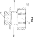
- an assembly intercalated between a torque tool and a fastening element, for measuring torques and tightening angles, generally referenced as 10, comprises in combination;
- Processing unit A includes:
- the user will mount assembly 10, intercalated between a torque tool (not shown) and a fastening element (also not shown), for measuring torques and tightening angles, onto torque tool, such as a powered torque tool (not shown), by inserting the driving tool shaft of the latter into first engaging cavity 110, wherein may be retained by a locking pin.
- torque tool such as a powered torque tool (not shown)
- the user will then engage the fastener assembly 19 (not shown) with assembly 10, respectively its second engaging cavity 120.
- the user by using display 410 and keypad 415 , can select and modify the ultimate torque and angular displacement values, which are displayed in standard engineering units, by incrementing or decrementing the values via the keypad pushbuttons, or select from a pre-established list of values. By the same means the user may also change the desired standard engineering units for torque, for example NM, ft lbs, etc. Display 410 also indicates the operational readiness of assembly 10.
- microcontroller 405 Under normal operation, microcontroller 405 , by means of display 410 , will indicate "Ready” when the device has sufficient battery power, and is ready for measurements.
- microcontroller 405 will indicate the final measured parameter(s) (applied torque and/or angular displacement) via display 410 and via pass/fail indicator 418 . During the tightening process, microcontroller 405 monitors and stores the running measured parameter(s) (applied torque and/or angular displacement) for analysis by the user.
- the user selects an ultimate torque value, and a desired ultimate angular displacement value, therefore providing a means for after the ultimate torque value is achieved microcontroller 405 will zero the position count, and at a pre-established threshold prior to the desired ultimate angular position, the microcontroller 405 sends a signal, or plurality of signals via connection port 420 to the tool's own controller (not shown) to control the approach of, and the shutoff of, the tool to achieve the imposed parameter (applied torque and/or angular displacement) within the desired upper and lower parameter limits.
Claims (1)
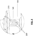
- Anordnung (10), interkaliert zwischen einem Drehmomentwerkzeug und einem Befestigungselement, zur Messung von Drehmomenten und Winkelverschiebung von Befestigungsmitteln, umfassend, in Kombination:- eine Buchsen-Teilanordnung (100), die einen einstückigen langgestreckten Körper aufweist, welcher an einem Ende einen ersten Eingriffshohlraum (110) und an einem entgegengesetzten Ende einen zweiten Eingriffshohlraum (120) beinhaltet; und worin ein nach außen offener, ringförmiger Kanal (130) integriert ist, der zwischen den Enden der Buchsen-Teilanordnung vorgesehen ist;- eine Dehnungsaufnehmer-Teilanordnung (200) zum Messen von Torsionsspannungen auf der Buchsen-Teilanordnung (100), die in dem nach außen offenen, ringförmigen Kanal (130) montiert ist;- eine an der Buchsen-Teilanordnung (100) angebrachte kreisförmige Abdeckung (300) zum Umschließen des nach außen offenen, ringförmigen Kanals (130); und- eine elektronische Teilanordnung (400) zum Umwandeln der Torsionsspannungen auf der Buchsen-Teilanordnung (100) in Standard-Drehmomentwerte und zur Ermittlung von Anzieh-Winkelverschiebungen; wobei die elektronische Teilanordnung mit der Dehnungsaufnehmer-Teilanordnung (200) verschaltet ist und auf der kreisförmigen Abdeckung (300) montiert ist, sodass sie der Dehnungsaufnehmer-Teilanordnung (200) zugewandt ist;wobei die Buchsen-Teilanordnung (100) den ersten Eingriffshohlraum (110) beinhaltet, der so ausgebildet ist, dass er konform dem Drehmomentwerkzeug-Austrittsschaft, üblicherweise vom Vierkanttyp, ist und damit in Eingriff tritt; wobei der zweite Eingriffshohlraum (120) so ausgebildet ist, dass er mit dem Befestigungselement, mit einer spezifischen Größe, konform ist und damit in Eingriff tritt; wobei der nach außen offene, ringförmige Kanal (130) mit einer kreisförmigen Bodenfläche (140) zum Montieren der Dehnungsaufnehmer-Teilanordnung (200) versehen ist;
wobei die Dehnungsaufnehmer-Teilanordnung (200) vier Dehnungsmessstreifen (210) umfasst, in gleichen Abständen voneinander auf der kreisförmigen Bodenfläche (140) angeordnet, die zum Messen von Torsionsspannungen bestimmt sind; wobei jeder der vier Dehnungsmessstreifen (210) vom Typ 45 Grad-Doppelgitter-Scherspannungsmuster ist und aus Konstantan hergestellt ist, umfassend ein Paar von parallelen, nebeneinander angeordneten Dehnungselementen (220), so angeordnet, dass eine Konvergenzlinie der parallelen, nebeneinander angeordneten Dehnungselemente (220) parallel zur Symmetrie-Längsachse der Buchsen-Teilanordnung (100) ist, nur zum Messen von Torsionsspannungen; wobei die Dehnungsaufnehmer-Teilanordnung (200) in einer Wheatstone-Brückenanordnung verdrahtet sind, um analoge elektrische Spannungssignale zu produzieren, die nur zu Torsionsspannungen in der Buchsenanordnung (100), und daher in dem Befestigungselement, proportional sind;
wobei die kreisförmige Abdeckungs-Teilanordnung (300) ein erstes und ein zweites halbkreisförmiges Segment (305, 310) umfasst; wobei in das erste halbkreisförmige Segment (305) ein axialer Vorsprung und diametral entgegengesetzte Gewindeöffnungen (355) integriert sind; wobei in das zweite halbkreisförmige Segment (310) ein Paar von Befestigungsöffnungen (360) integriert ist, die den besagten diametral entgegengesetzten Gewindeöffnungen (355) entsprechen; wobei die diametral entgegengesetzten Gewindeöffnungen (355) und das Paar von Befestigungsöffnungen (360) zur Befestigung des ersten und des zweiten halbkreisförmigen Segments (305, 310) mittels Befestigungselementen genutzt werden;
wobei die elektronische Teilanordnung (400) eine Verarbeitungseinheit, eine Benutzerschnittstelleneinheit und eine Stromversorgungseinheit umfasst;
wobei die Verarbeitungseinheit eine Mikrosteuerung (405) zur digitalen und analogen Signalverarbeitung beinhaltet, die an dem ersten halbkreisförmigen Segment (305) montiert und mit der Dehnungsaufnehmer-Teilanordnung (200) verbunden ist, zum Umwandeln der Torsionsspannung in Standard-Drehmoment-Konstruktionseinheiten, zum Messen von Winkelverschiebung mittels eines Sensors zur Bereitstellung von Datum/Zeit-Funktion zur Zeitmarkierung von Anziehzyklen und gemessenen Parametern, und zur Parameter- und Konfigurationsspeicherung;
wobei die Benutzerschnittstelleneinheit beinhaltet:eine an dem ersten halbkreisförmigen Segment (305) montierte und mit der Mikrosteuerung (405) verschaltete Anzeige (410), zur Darstellung der ausgewählten auferlegten Parameter und zur Darstellung der laufenden und letzten gemessenen Parameter;einen an dem ersten halbkreisförmigen Segment (305) montierten und mit der Verarbeitungseinheit verschalteten Verbindungsanschluss (420), zur Kommunikation mit einer externen Vorrichtung oder zum Zweck der Steuerung der Drehmomentwerkzeug-Abschaltung an dem auferlegten Parameter;ein mit der Verarbeitungseinheit verschaltetes Tastenfeld (415) zum Auswählen des gewünschten Parameters zur Verifikation, oder zum Auswählen des Parameters, bei dem der eigenen Steuerung des Drehmomentwerkzeugs signalisiert werden muss, bei dem auferlegten Parameter abzuschalten;eine mit der Verarbeitungseinheit verschaltete Erfolgreich/Fehler-Anzeigevorrichtung (418), um darzustellen, ob der gemessene Parameter innerhalb der zuvor erstellten oberen Parametergrenze und unteren Parametergrenze liegt, wie vom Benutzer definiert; undwobei die Stromversorgungseinheit beinhaltet:
eine Stromquelle in Form einer Batterie (430) und einen Batterielade- und Schutzkreis.
Applications Claiming Priority (1)
| Application Number | Priority Date | Filing Date | Title |
|---|---|---|---|
| PCT/CA2011/001001 WO2011156918A2 (en) | 2011-09-02 | 2011-09-02 | Assembly, intercalated between a torque tool and a fastening element, for measuring torques and tightening angles |
Publications (3)
| Publication Number | Publication Date |
|---|---|
| EP2800959A2 EP2800959A2 (de) | 2014-11-12 |
| EP2800959A4 EP2800959A4 (de) | 2015-10-21 |
| EP2800959B1 true EP2800959B1 (de) | 2019-05-22 |
Family
ID=45348599
Family Applications (1)
| Application Number | Title | Priority Date | Filing Date |
|---|---|---|---|
| EP11795003.0A Active EP2800959B1 (de) | 2011-09-02 | 2011-09-02 | Anordnung zwischen einem drehmomentwerkzeug und befestigungselement zur messung von drehmomenten und anzugswinkeln |
Country Status (6)
| Country | Link |
|---|---|
| US (1) | US8590402B2 (de) |
| EP (1) | EP2800959B1 (de) |
| CA (1) | CA2811139C (de) |
| DK (1) | DK2800959T3 (de) |
| ES (1) | ES2742352T3 (de) |
| WO (1) | WO2011156918A2 (de) |
Families Citing this family (10)
| Publication number | Priority date | Publication date | Assignee | Title |
|---|---|---|---|---|
| US20130279298A1 (en) * | 2012-04-19 | 2013-10-24 | William Mark PRENTICE | Monitoring of underwater mooring lines |
| CN103234451B (zh) * | 2013-03-28 | 2015-08-19 | 重庆理工大学 | 一种可实现在线自标定的时栅角位移传感器系统及方法 |
| US9395257B2 (en) * | 2013-05-10 | 2016-07-19 | Snap-On Incorporated | Electronic torque tool with integrated real-time clock |
| CN103335835B (zh) * | 2013-07-08 | 2016-03-02 | 中国空间技术研究院 | 一种卡箍的使用性能试验装置、试验方法、装配参数的选择方法以及质量检验方法 |
| PL2921242T3 (pl) * | 2014-03-17 | 2017-12-29 | Raccorderie Metalliche S.P.A. | Złączka zaciskana |
| DE202016008911U1 (de) * | 2016-08-01 | 2020-08-27 | Nuton GmbH | Ein- oder mehrachsige Kraftmesseinrichtung mit kurzer Verformungszone |
| TWM556196U (zh) * | 2016-09-13 | 2018-03-01 | 米沃奇電子工具公司 | 電動棘輪式扭力扳手 |
| US10625405B2 (en) | 2016-09-13 | 2020-04-21 | Milwaukee Electric Tool Corporation | Powered ratcheting torque wrench |
| US11453105B2 (en) | 2016-09-13 | 2022-09-27 | Milwaukee Electric Tool Corporation | Powered ratcheting torque wrench |
| EP3412412A1 (de) * | 2017-06-09 | 2018-12-12 | Wezag GmbH Werkzeugfabrik | Manuell betätigtes handwerkzeug |
Family Cites Families (28)
| Publication number | Priority date | Publication date | Assignee | Title |
|---|---|---|---|---|
| US3753625A (en) * | 1971-07-28 | 1973-08-21 | R Fabrizio | Cutting tool holder or adaptor |
| US3889490A (en) * | 1974-05-16 | 1975-06-17 | Felix J Nadolny | Torque control adaptor for ratchet wrench |
| DE3214889A1 (de) * | 1982-04-22 | 1983-10-27 | Robert Bosch Gmbh, 7000 Stuttgart | Messwertgeber fuer drehmoment- und/oder drehwinkelmessung, insbesondere an motorgetriebenen schraubern |
| FR2543041B1 (fr) * | 1983-03-25 | 1985-08-09 | Baudet Jean Pierre | Procede et installation de serrage d'une liaison de type vis, avec controle de la tension mecanique appliquee a la vis |
| DE3528364A1 (de) * | 1985-08-07 | 1987-02-19 | Helmut Erb Elektr Messtechnik | Reaktionsdrehmomentaufnehmer und verfahren zu seiner messbereichsanpassung |
| US4802540A (en) * | 1988-01-29 | 1989-02-07 | Consolidated Devices Inc. | Electronic weighing scales |
| JPH02116479A (ja) * | 1988-10-21 | 1990-05-01 | Fujitsu Ltd | ネジ締め装置 |
| US5058439A (en) * | 1990-06-06 | 1991-10-22 | The Babcock & Wilcox Company | Ut socket assembly |
| US5347871A (en) * | 1992-02-03 | 1994-09-20 | Teledyne Industries, Inc. | Strain sensor |
| DE19525231B4 (de) * | 1995-07-11 | 2004-03-04 | Hottinger Baldwin Messtechnik Gmbh | Drehmomentsensor |
| US5898598A (en) | 1996-10-25 | 1999-04-27 | Cooper Technologies Company | System and apparatus for a torque transducer with data processing capabilities |
| US6196071B1 (en) | 1998-02-23 | 2001-03-06 | Robert D. Shomo | Torque indicator socket |
| DE19842231C1 (de) * | 1998-09-15 | 2000-07-06 | Test Gmbh | Meßvorrichtung zur Bestimmung des Gesamtanzugsmoments, des Kopfreibungsmoments und der Vorspannkraft einer angezogenen Schraubverbindung |
| US6965835B2 (en) * | 2001-09-28 | 2005-11-15 | Spx Corporation | Torque angle sensing system and method with angle indication |
| US6629055B2 (en) | 2001-09-28 | 2003-09-30 | Spx Corporation | Apparatus and method for sensing torque angle |
| DE10217416C1 (de) * | 2002-04-18 | 2003-07-31 | Ivo Geilenbruegge | Drehmomentmessvorrichtung |
| US7082865B2 (en) * | 2003-05-01 | 2006-08-01 | Ryeson Corporation | Digital torque wrench |
| US7475619B2 (en) * | 2005-04-22 | 2009-01-13 | The Stanley Works | Over torque proof socket |
| WO2007062813A1 (de) * | 2005-12-01 | 2007-06-07 | Hottinger Baldwin Messtechnik Gmbh | Dehnungsmessstreifen |
| JP4724137B2 (ja) * | 2007-03-12 | 2011-07-13 | 前田金属工業株式会社 | 締付トルク測定ユニット及びボルト・ナット締付機 |
| US8083596B1 (en) * | 2007-11-26 | 2011-12-27 | Holmed Corporation | Torque limiter |
| CN201405312Y (zh) * | 2009-02-06 | 2010-02-17 | 苏州宝时得电动工具有限公司 | 动力工具 |
| TWM372771U (en) * | 2009-05-20 | 2010-01-21 | Legend Lifestyle Products Corp | Torque detection display device for tool |
| TWM378377U (en) * | 2009-11-10 | 2010-04-11 | Legend Lifestyle Products Corp | Twisting force testing device |
| CN201653623U (zh) * | 2009-11-20 | 2010-11-24 | 关弘科技股份有限公司 | 扭力测试装置 |
| TWM378815U (en) * | 2009-11-20 | 2010-04-21 | Jia-Ming Li | Adapter tool capable of sensing torque |
| TWM392713U (en) * | 2010-07-12 | 2010-11-21 | Legend Lifestyle Products Corp | Wireless torque wrench with angle correction feature |
| US20120119919A1 (en) * | 2010-11-15 | 2012-05-17 | Legend Lifestyle Products Corp. | Multifunctional torque detection device |
-
2011
- 2011-09-02 EP EP11795003.0A patent/EP2800959B1/de active Active
- 2011-09-02 ES ES11795003T patent/ES2742352T3/es active Active
- 2011-09-02 WO PCT/CA2011/001001 patent/WO2011156918A2/en active Application Filing
- 2011-09-02 US US13/261,598 patent/US8590402B2/en active Active
- 2011-09-02 DK DK11795003.0T patent/DK2800959T3/da active
- 2011-09-02 CA CA2811139A patent/CA2811139C/en active Active
Non-Patent Citations (1)
| Title |
|---|
| None * |
Also Published As
| Publication number | Publication date |
|---|---|
| EP2800959A4 (de) | 2015-10-21 |
| EP2800959A2 (de) | 2014-11-12 |
| US8590402B2 (en) | 2013-11-26 |
| CA2811139A1 (en) | 2011-12-22 |
| US20130199307A1 (en) | 2013-08-08 |
| CA2811139C (en) | 2018-03-20 |
| DK2800959T3 (da) | 2019-08-19 |
| WO2011156918A3 (en) | 2012-07-05 |
| ES2742352T3 (es) | 2020-02-14 |
| WO2011156918A2 (en) | 2011-12-22 |
Similar Documents
| Publication | Publication Date | Title |
|---|---|---|
| EP2800959B1 (de) | Anordnung zwischen einem drehmomentwerkzeug und befestigungselement zur messung von drehmomenten und anzugswinkeln | |
| US6810747B2 (en) | Test device for determining the friction and prestress values of screwed connections | |
| US9505109B2 (en) | Electronic torque wrench | |
| EP2248632B1 (de) | Drahtloses Datenübertragungs- und -empfangssystem | |
| EP1614506B1 (de) | Messeinheit zum Messen eines Drehmoments und Vorrichtung zum Festziehen mit einer Drehmomentanzeige | |
| US20030196497A1 (en) | Torque measuring device | |
| JP3190778U (ja) | 引張力測定可能な締結具 | |
| CN110806286A (zh) | 用于调整扭矩测量的工具和方法 | |
| JP6027670B1 (ja) | タッピンねじの締付軸力の決定方法及びその表示装置 | |
| US11396899B2 (en) | Bolt clamping force sensing washer | |
| CN102753311A (zh) | 用于上紧螺纹紧固件的装置 | |
| JP4453921B2 (ja) | 電動弁診断方法および装置 | |
| TWI754533B (zh) | 螺栓鎖固作業用的螺栓夾緊力傳感器 | |
| CN210361096U (zh) | 动力工具 | |
| US20220176526A1 (en) | Torque screwdriver arrangement and method for operating such a torque screwdriver arrangement | |
| JP2004239681A (ja) | 締付けトルク測定装置 | |
| CN113328482A (zh) | 在电子扭矩扳手中使用usb用户接口的方法和系统 | |
| KR20220010623A (ko) | 전동 공구 | |
| US7096747B1 (en) | Hand tool with twisting force measuring functions | |
| JPH0442027A (ja) | 螺子締付力測定装置 | |
| CN214793575U (zh) | 螺栓锁固作业用的螺栓夹紧力传感器 | |
| US11529719B2 (en) | Bolt clamping force transducer for bolt tightening operation | |
| EP3946816B1 (de) | Drehmomentapplikationswerkzeug | |
| JP4133525B2 (ja) | 着脱型センサ | |
| CN114838861A (zh) | 螺栓锁固作业用的螺栓夹紧力传感器 |
Legal Events
| Date | Code | Title | Description |
|---|---|---|---|
| PUAI | Public reference made under article 153(3) epc to a published international application that has entered the european phase |
Free format text: ORIGINAL CODE: 0009012 |
|
| 17P | Request for examination filed |
Effective date: 20140331 |
|
| AK | Designated contracting states |
Kind code of ref document: A2 Designated state(s): AL AT BE BG CH CY CZ DE DK EE ES FI FR GB GR HR HU IE IS IT LI LT LU LV MC MK MT NL NO PL PT RO RS SE SI SK SM TR |
|
| DAX | Request for extension of the european patent (deleted) | ||
| A4 | Supplementary search report drawn up and despatched |
Effective date: 20150921 |
|
| RIC1 | Information provided on ipc code assigned before grant |
Ipc: B25B 23/142 20060101ALI20150915BHEP Ipc: G01B 7/30 20060101ALI20150915BHEP Ipc: G01L 5/24 20060101AFI20150915BHEP |
|
| RIC1 | Information provided on ipc code assigned before grant |
Ipc: B25B 23/142 20060101ALI20181018BHEP Ipc: B25B 13/06 20060101ALI20181018BHEP Ipc: G01L 5/24 20060101AFI20181018BHEP |
|
| GRAP | Despatch of communication of intention to grant a patent |
Free format text: ORIGINAL CODE: EPIDOSNIGR1 |
|
| STAA | Information on the status of an ep patent application or granted ep patent |
Free format text: STATUS: GRANT OF PATENT IS INTENDED |
|
| INTG | Intention to grant announced |
Effective date: 20181129 |
|
| GRAS | Grant fee paid |
Free format text: ORIGINAL CODE: EPIDOSNIGR3 |
|
| GRAA | (expected) grant |
Free format text: ORIGINAL CODE: 0009210 |
|
| STAA | Information on the status of an ep patent application or granted ep patent |
Free format text: STATUS: THE PATENT HAS BEEN GRANTED |
|
| AK | Designated contracting states |
Kind code of ref document: B1 Designated state(s): AL AT BE BG CH CY CZ DE DK EE ES FI FR GB GR HR HU IE IS IT LI LT LU LV MC MK MT NL NO PL PT RO RS SE SI SK SM TR |
|
| REG | Reference to a national code |
Ref country code: GB Ref legal event code: FG4D |
|
| REG | Reference to a national code |
Ref country code: CH Ref legal event code: EP |
|
| REG | Reference to a national code |
Ref country code: IE Ref legal event code: FG4D |
|
| REG | Reference to a national code |
Ref country code: DE Ref legal event code: R096 Ref document number: 602011059225 Country of ref document: DE |
|
| REG | Reference to a national code |
Ref country code: AT Ref legal event code: REF Ref document number: 1136684 Country of ref document: AT Kind code of ref document: T Effective date: 20190615 |
|
| REG | Reference to a national code |
Ref country code: DK Ref legal event code: T3 Effective date: 20190816 |
|
| REG | Reference to a national code |
Ref country code: NL Ref legal event code: FP |
|
| REG | Reference to a national code |
Ref country code: SE Ref legal event code: TRGR |
|
| REG | Reference to a national code |
Ref country code: LT Ref legal event code: MG4D |
|
| PG25 | Lapsed in a contracting state [announced via postgrant information from national office to epo] |
Ref country code: LT Free format text: LAPSE BECAUSE OF FAILURE TO SUBMIT A TRANSLATION OF THE DESCRIPTION OR TO PAY THE FEE WITHIN THE PRESCRIBED TIME-LIMIT Effective date: 20190522 Ref country code: AL Free format text: LAPSE BECAUSE OF FAILURE TO SUBMIT A TRANSLATION OF THE DESCRIPTION OR TO PAY THE FEE WITHIN THE PRESCRIBED TIME-LIMIT Effective date: 20190522 Ref country code: PT Free format text: LAPSE BECAUSE OF FAILURE TO SUBMIT A TRANSLATION OF THE DESCRIPTION OR TO PAY THE FEE WITHIN THE PRESCRIBED TIME-LIMIT Effective date: 20190922 Ref country code: NO Free format text: LAPSE BECAUSE OF FAILURE TO SUBMIT A TRANSLATION OF THE DESCRIPTION OR TO PAY THE FEE WITHIN THE PRESCRIBED TIME-LIMIT Effective date: 20190822 Ref country code: HR Free format text: LAPSE BECAUSE OF FAILURE TO SUBMIT A TRANSLATION OF THE DESCRIPTION OR TO PAY THE FEE WITHIN THE PRESCRIBED TIME-LIMIT Effective date: 20190522 Ref country code: FI Free format text: LAPSE BECAUSE OF FAILURE TO SUBMIT A TRANSLATION OF THE DESCRIPTION OR TO PAY THE FEE WITHIN THE PRESCRIBED TIME-LIMIT Effective date: 20190522 |
|
| PG25 | Lapsed in a contracting state [announced via postgrant information from national office to epo] |
Ref country code: GR Free format text: LAPSE BECAUSE OF FAILURE TO SUBMIT A TRANSLATION OF THE DESCRIPTION OR TO PAY THE FEE WITHIN THE PRESCRIBED TIME-LIMIT Effective date: 20190823 Ref country code: BG Free format text: LAPSE BECAUSE OF FAILURE TO SUBMIT A TRANSLATION OF THE DESCRIPTION OR TO PAY THE FEE WITHIN THE PRESCRIBED TIME-LIMIT Effective date: 20190822 Ref country code: RS Free format text: LAPSE BECAUSE OF FAILURE TO SUBMIT A TRANSLATION OF THE DESCRIPTION OR TO PAY THE FEE WITHIN THE PRESCRIBED TIME-LIMIT Effective date: 20190522 Ref country code: LV Free format text: LAPSE BECAUSE OF FAILURE TO SUBMIT A TRANSLATION OF THE DESCRIPTION OR TO PAY THE FEE WITHIN THE PRESCRIBED TIME-LIMIT Effective date: 20190522 |
|
| REG | Reference to a national code |
Ref country code: AT Ref legal event code: MK05 Ref document number: 1136684 Country of ref document: AT Kind code of ref document: T Effective date: 20190522 |
|
| PG25 | Lapsed in a contracting state [announced via postgrant information from national office to epo] |
Ref country code: EE Free format text: LAPSE BECAUSE OF FAILURE TO SUBMIT A TRANSLATION OF THE DESCRIPTION OR TO PAY THE FEE WITHIN THE PRESCRIBED TIME-LIMIT Effective date: 20190522 Ref country code: AT Free format text: LAPSE BECAUSE OF FAILURE TO SUBMIT A TRANSLATION OF THE DESCRIPTION OR TO PAY THE FEE WITHIN THE PRESCRIBED TIME-LIMIT Effective date: 20190522 Ref country code: SK Free format text: LAPSE BECAUSE OF FAILURE TO SUBMIT A TRANSLATION OF THE DESCRIPTION OR TO PAY THE FEE WITHIN THE PRESCRIBED TIME-LIMIT Effective date: 20190522 Ref country code: CZ Free format text: LAPSE BECAUSE OF FAILURE TO SUBMIT A TRANSLATION OF THE DESCRIPTION OR TO PAY THE FEE WITHIN THE PRESCRIBED TIME-LIMIT Effective date: 20190522 Ref country code: RO Free format text: LAPSE BECAUSE OF FAILURE TO SUBMIT A TRANSLATION OF THE DESCRIPTION OR TO PAY THE FEE WITHIN THE PRESCRIBED TIME-LIMIT Effective date: 20190522 |
|
| REG | Reference to a national code |
Ref country code: ES Ref legal event code: FG2A Ref document number: 2742352 Country of ref document: ES Kind code of ref document: T3 Effective date: 20200214 |
|
| REG | Reference to a national code |
Ref country code: DE Ref legal event code: R097 Ref document number: 602011059225 Country of ref document: DE |
|
| PG25 | Lapsed in a contracting state [announced via postgrant information from national office to epo] |
Ref country code: SM Free format text: LAPSE BECAUSE OF FAILURE TO SUBMIT A TRANSLATION OF THE DESCRIPTION OR TO PAY THE FEE WITHIN THE PRESCRIBED TIME-LIMIT Effective date: 20190522 |
|
| PLBE | No opposition filed within time limit |
Free format text: ORIGINAL CODE: 0009261 |
|
| STAA | Information on the status of an ep patent application or granted ep patent |
Free format text: STATUS: NO OPPOSITION FILED WITHIN TIME LIMIT |
|
| 26N | No opposition filed |
Effective date: 20200225 |
|
| PG25 | Lapsed in a contracting state [announced via postgrant information from national office to epo] |
Ref country code: PL Free format text: LAPSE BECAUSE OF FAILURE TO SUBMIT A TRANSLATION OF THE DESCRIPTION OR TO PAY THE FEE WITHIN THE PRESCRIBED TIME-LIMIT Effective date: 20190522 |
|
| PG25 | Lapsed in a contracting state [announced via postgrant information from national office to epo] |
Ref country code: SI Free format text: LAPSE BECAUSE OF FAILURE TO SUBMIT A TRANSLATION OF THE DESCRIPTION OR TO PAY THE FEE WITHIN THE PRESCRIBED TIME-LIMIT Effective date: 20190522 Ref country code: MC Free format text: LAPSE BECAUSE OF FAILURE TO SUBMIT A TRANSLATION OF THE DESCRIPTION OR TO PAY THE FEE WITHIN THE PRESCRIBED TIME-LIMIT Effective date: 20190522 |
|
| REG | Reference to a national code |
Ref country code: CH Ref legal event code: PL |
|
| PG25 | Lapsed in a contracting state [announced via postgrant information from national office to epo] |
Ref country code: CH Free format text: LAPSE BECAUSE OF NON-PAYMENT OF DUE FEES Effective date: 20190930 Ref country code: LU Free format text: LAPSE BECAUSE OF NON-PAYMENT OF DUE FEES Effective date: 20190902 Ref country code: LI Free format text: LAPSE BECAUSE OF NON-PAYMENT OF DUE FEES Effective date: 20190930 Ref country code: IE Free format text: LAPSE BECAUSE OF NON-PAYMENT OF DUE FEES Effective date: 20190902 |
|
| PG25 | Lapsed in a contracting state [announced via postgrant information from national office to epo] |
Ref country code: CY Free format text: LAPSE BECAUSE OF FAILURE TO SUBMIT A TRANSLATION OF THE DESCRIPTION OR TO PAY THE FEE WITHIN THE PRESCRIBED TIME-LIMIT Effective date: 20190522 |
|
| PG25 | Lapsed in a contracting state [announced via postgrant information from national office to epo] |
Ref country code: IS Free format text: LAPSE BECAUSE OF FAILURE TO SUBMIT A TRANSLATION OF THE DESCRIPTION OR TO PAY THE FEE WITHIN THE PRESCRIBED TIME-LIMIT Effective date: 20190922 |
|
| PG25 | Lapsed in a contracting state [announced via postgrant information from national office to epo] |
Ref country code: HU Free format text: LAPSE BECAUSE OF FAILURE TO SUBMIT A TRANSLATION OF THE DESCRIPTION OR TO PAY THE FEE WITHIN THE PRESCRIBED TIME-LIMIT; INVALID AB INITIO Effective date: 20110902 Ref country code: MT Free format text: LAPSE BECAUSE OF FAILURE TO SUBMIT A TRANSLATION OF THE DESCRIPTION OR TO PAY THE FEE WITHIN THE PRESCRIBED TIME-LIMIT Effective date: 20190522 |
|
| PG25 | Lapsed in a contracting state [announced via postgrant information from national office to epo] |
Ref country code: MK Free format text: LAPSE BECAUSE OF FAILURE TO SUBMIT A TRANSLATION OF THE DESCRIPTION OR TO PAY THE FEE WITHIN THE PRESCRIBED TIME-LIMIT Effective date: 20190522 |
|
| PGFP | Annual fee paid to national office [announced via postgrant information from national office to epo] |
Ref country code: TR Payment date: 20230904 Year of fee payment: 13 Ref country code: NL Payment date: 20230925 Year of fee payment: 13 Ref country code: IT Payment date: 20230925 Year of fee payment: 13 Ref country code: GB Payment date: 20230830 Year of fee payment: 13 |
|
| PGFP | Annual fee paid to national office [announced via postgrant information from national office to epo] |
Ref country code: SE Payment date: 20230830 Year of fee payment: 13 Ref country code: FR Payment date: 20230928 Year of fee payment: 13 Ref country code: DK Payment date: 20230829 Year of fee payment: 13 Ref country code: BE Payment date: 20230928 Year of fee payment: 13 |
|
| PGFP | Annual fee paid to national office [announced via postgrant information from national office to epo] |
Ref country code: ES Payment date: 20231003 Year of fee payment: 13 |
|
| PGFP | Annual fee paid to national office [announced via postgrant information from national office to epo] |
Ref country code: DE Payment date: 20230928 Year of fee payment: 13 |