EP2800719B1 - Trommelfördermaschine mit einer angetriebenen hauptwelle - Google Patents
Trommelfördermaschine mit einer angetriebenen hauptwelle Download PDFInfo
- Publication number
- EP2800719B1 EP2800719B1 EP13771410.1A EP13771410A EP2800719B1 EP 2800719 B1 EP2800719 B1 EP 2800719B1 EP 13771410 A EP13771410 A EP 13771410A EP 2800719 B1 EP2800719 B1 EP 2800719B1
- Authority
- EP
- European Patent Office
- Prior art keywords
- drum
- wheel
- engagement
- toothed structure
- coupler
- Prior art date
- Legal status (The legal status is an assumption and is not a legal conclusion. Google has not performed a legal analysis and makes no representation as to the accuracy of the status listed.)
- Active
Links
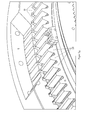
Images







Classifications
-
- B—PERFORMING OPERATIONS; TRANSPORTING
- B66—HOISTING; LIFTING; HAULING
- B66D—CAPSTANS; WINCHES; TACKLES, e.g. PULLEY BLOCKS; HOISTS
- B66D1/00—Rope, cable, or chain winding mechanisms; Capstans
- B66D1/02—Driving gear
- B66D1/14—Power transmissions between power sources and drums or barrels
-
- B—PERFORMING OPERATIONS; TRANSPORTING
- B66—HOISTING; LIFTING; HAULING
- B66D—CAPSTANS; WINCHES; TACKLES, e.g. PULLEY BLOCKS; HOISTS
- B66D1/00—Rope, cable, or chain winding mechanisms; Capstans
- B66D1/26—Rope, cable, or chain winding mechanisms; Capstans having several drums or barrels
-
- F—MECHANICAL ENGINEERING; LIGHTING; HEATING; WEAPONS; BLASTING
- F16—ENGINEERING ELEMENTS AND UNITS; GENERAL MEASURES FOR PRODUCING AND MAINTAINING EFFECTIVE FUNCTIONING OF MACHINES OR INSTALLATIONS; THERMAL INSULATION IN GENERAL
- F16D—COUPLINGS FOR TRANSMITTING ROTATION; CLUTCHES; BRAKES
- F16D11/00—Clutches in which the members have interengaging parts
- F16D11/02—Clutches in which the members have interengaging parts disengaged by a contact of a part mounted on the clutch with a stationarily-mounted member
- F16D11/04—Clutches in which the members have interengaging parts disengaged by a contact of a part mounted on the clutch with a stationarily-mounted member with clutching members movable only axially
-
- F—MECHANICAL ENGINEERING; LIGHTING; HEATING; WEAPONS; BLASTING
- F16—ENGINEERING ELEMENTS AND UNITS; GENERAL MEASURES FOR PRODUCING AND MAINTAINING EFFECTIVE FUNCTIONING OF MACHINES OR INSTALLATIONS; THERMAL INSULATION IN GENERAL
- F16D—COUPLINGS FOR TRANSMITTING ROTATION; CLUTCHES; BRAKES
- F16D11/00—Clutches in which the members have interengaging parts
- F16D11/08—Clutches in which the members have interengaging parts actuated by moving a non-rotating part axially
- F16D11/10—Clutches in which the members have interengaging parts actuated by moving a non-rotating part axially with clutching members movable only axially
-
- F—MECHANICAL ENGINEERING; LIGHTING; HEATING; WEAPONS; BLASTING
- F16—ENGINEERING ELEMENTS AND UNITS; GENERAL MEASURES FOR PRODUCING AND MAINTAINING EFFECTIVE FUNCTIONING OF MACHINES OR INSTALLATIONS; THERMAL INSULATION IN GENERAL
- F16D—COUPLINGS FOR TRANSMITTING ROTATION; CLUTCHES; BRAKES
- F16D11/00—Clutches in which the members have interengaging parts
- F16D11/14—Clutches in which the members have interengaging parts with clutching members movable only axially
Definitions
- the invention relates to a drum carrier with a driven main shaft, at least one arranged on the main shaft Lostrommel with a parking brake, a hiding device for releasably connecting the Lostrommel and main shaft, a rotatably connected to the Lostrommel drum wheel with an internal toothing, a non-rotatably connected to the main shaft shaft with an outer toothing, a Kuppelrad with an outer and an inner toothing, which is axially displaceable in an engaging and disengaging on the outer toothing of the shaft wheel, a front side rotatably connected to the Kuppelrad sliding ring and a frame fixed to the drum carrier switching device arranged to move the Sliding rings in an engagement and disengagement, has, wherein the external toothing of the coupling wheel by the axial displacement in the engagement direction in engagement and by the axial displacement in the disengagement except Ein handle with the internal toothing of the drum wheel can be brought. Moreover, the invention relates to a method for engaging or disengaging a hiding device of such a drum
- a cable drum is used as a cable carrier on which the conveyor rope is wound or unwound.
- Double drum machines can be designed, for example, as blair machines or bobbins. Double drum machines are available both with a fixed drum and a Lostrommel, as well as with two Lostrommeln. The Lostrommeln be connected via a switchable coupling, the hiding, releasably connected to the main shaft. For each lot drum of the drum carrier, it is necessary that Hide a separate brake for the Lostrommel is present.
- the winding direction of the rope on the drums of the double drum machine is in opposite directions, so that the same direction of rotation of the main shaft, the rope of a drum wound and the other is unwound.
- both drums can be offset relative to each other in the circumferential direction.
- the Lostrommel is blocked with its associated brake and uncoupled from the other drum, in particular a fixed drum.
- the Lostrommel does not rotate when positioning the second conveyor with the help of the other drum.
- the Lostrommel is again coupled to the drive shaft and released the brake.
- Double drum haulers with hiding devices therefore allow for the conveyance from different depths, so that, for example, a conveyor loaded underground, while at the same time the other is discharged over days. This function is particularly important when sinking a shaft, since here the depth of the shaft changes permanently, for example, to promote overburden or to do work while sinking in the shaft. Special emphasis is placed on a fast hiding process with high security in function, operation and availability.
- the prior art hiding device for a supplied by the company Gutehoffnungsdazzling, Aktienippo for mining and metallurgical plant (GHH short) drum machine from 1987 is based on the partial section through a hiding on the basis of FIG. 1 explained in more detail.
- the reference numerals appearing in the description of the prior art relate exclusively to FIG. 1 .
- One internally toothed drum wheel (1) is screwed to a side plate, not shown, a lotto drum, not shown.
- a wave wheel (2), as well as the fixed drum, not shown rotatably screwed by flanges with the main shaft, not shown.
- a coupling wheel (5), a sliding ring (6) and a switching element designed as a switching ring (7) are arranged axially displaceable.
- the switching ring (7) is fixed to the frame connected to the foundation of the double drum machine associated brackets for the hydraulic displacement cylinder, not shown.
- the switching ring (7) slides in a circumferential groove (8) of the sliding ring (6), while the unillustrated Lostrommel rotates in the engaged state of the hiding device.
- the engagement and disengagement of the hiding device takes place in the secured by braking standstill of the double drum machine.
- secure the hydraulic displacement cylinder, the position of the axially in the engagement and Ausrückraum on the outer toothing (4) of the shaft wheel (3) slidable Kuppelrades (5).
- the DE 922 194 B discloses a drum carrier with a hiding device in which a brake drum provided with a driven main shaft can be coupled.
- a sliding sleeve with external teeth is mounted as a coupling device.
- the external toothing can be brought into and out of engagement by displacement of the sliding sleeve in the axial direction of the drive shaft with an internal toothing of a rotatably connected to the Lostrommel intermediate part.
- the displacement of the sliding sleeve takes place with a mounted on the drum shaft movement device.
- the invention is therefore the object of the invention to provide a drum carrier, the hiding device effectively prevents unwanted disengagement of the coupling wheel of the hiding device, especially under load of the Lostrommel without mounting additional elements.
- the problem is solved in a drum carrier of the type mentioned in that at least one locking body is attached to the coupling wheel, the teeth of the internal teeth of the drum wheel having a circumferential direction of the drum wheel groove for receiving the locking body, between the teeth of the internal teeth of Drum wheel and the teeth of the external toothing of the coupling wheel is a game, so that by turning the indented coupling wheel relative to the drum wheel by the amount of play each locking body in one of the grooves in and out of engagement can be brought.
- the transmitted from the Lostrommel to the main shaft torque holds the locking body of the engaged Kuppelrades safely in their locked position in the groove.
- the play between the teeth of the internal toothing of the drum wheel and the teeth of the external toothing of the coupling wheel is caused by the fact that in the internal toothing of the drum wheel, the tooth flanks are displaced on one side in the circumferential direction. This results in a sufficient clearance to the teeth of the external toothing of the coupling wheel, so that by turning the indented coupling wheel relative to the drum wheel by the amount of the game each locking body in one of the grooves and disengagement can be brought.
- the locking bodies engageable with the grooves effectively prevent displacement of the coupling wheel axially in both directions. This will not only the previously observed Effect of unwanted disengagement of the Kuppelrades prevented, but also an unwanted counter-rotating movement of the Kuppelrades in the direction of engagement. This would burn the grease in the same way and melt the sliding metal.
- the locking body is arranged in particular on the rear end side in the direction of engagement of the coupling wheel of one of the teeth of the external toothing of the coupling wheel.
- the arrangement of the locking body on the front allows retrofitting existing drum conveyors with the hiding.
- Each locking body protrudes beyond one of the two tooth flanks of one of the teeth of the external toothing of the coupling wheel, which is the tooth flank, which rests on a tooth flank of the drum wheel under the load of the torque applied to the main shaft by the Lostrommel.
- the front side of the locking body may also be arranged on the tooth flank itself and extending from the surface of the tooth flank in the interdental space.
- a plurality of locking bodies are screwed to the front sides of the teeth of the outer toothing of the coupling wheel over the circumference of the coupling wheel.
- the blocking body is designed in particular as a plate and projects slightly beyond the tooth flank in the circumferential direction. By turning the coupling wheel he locks in the groove provided.
- the drum carrier has at least one stop.
- the stopper is positioned in such a way that when closing the coupling wheel each locking body in extension one of the circumferentially extending grooves lies.
- the stop is attached to the Kuppelrad and has a stop surface for a tooth of the internal toothing of the drum wheel.
- the stop and at least one locking body are integrally connected to a pawl with each other.
- the pawls are preferably designed so that they can be mounted without changing the construction so that the locking body engage in another direction of rotation of the drum wheel.
- the hiding device is, if such pawls are used, designed for both moment directions. This avoids manufacturing errors and makes the components independent of the direction of torque of a drum.
- An automatic precise positioning of the locking body in extension of the groove is achieved when a side wall of the groove cooperates with the stop surface of the stop.
- This cooperation is preferably achieved by a part of each tooth of the internal toothing of the drum wheel protruding when the coupling wheel is engaged, having a lower tooth height than the engaging part of each tooth of the internal toothing of the drum wheel, in which protruding part the groove runs and the tooth height of the protruding part is determined so that upon axial displacement of the coupling wheel in the direction of engagement only the end face of the engaged part of the tooth comes to rest on the stop surface.
- the locking body In order to hold the locking body in position and to absorb the forces when the hydraulic cylinder drive the load against the teeth of the drum wheel with full load, the locking body is in an advantageous embodiment of the invention with connected to a reinforcing element attached to the coupling wheel.
- a filling piece may be arranged between the reinforcing element and the blocking body in order to bridge the distance to the reinforcing element.
- the filler and the reinforcing element can also be made in one piece.
- the sliding ring is internally toothed.
- the length of the teeth of the coupling wheel and the sliding ring ensure that a secure axial guidance takes place without jamming.
- Coupling and sliding ring are preferably designed for production reasons as separate components that are rotatably connected to each other.
- the Kuppelrad and the sliding ring can also be made in one piece.
- the internal gears of Kuppelrad and sliding ring are preferably designed as trapezoidal teeth in the interest of good leadership.
- the external teeth of the coupling wheel and the meshing with the coupling wheel internal teeth of the drum wheel are preferably designed as involute.
- the sliding ring is provided in an advantageous embodiment of the invention with an annular collar which is rotatably connected to the sliding ring.
- the switching element comprises at least one, preferably two hydraulic cylinders whose piston rod is provided in each case at the end with a claw enclosing the collar. In order to guide and position the claws, these are preferably connected to one another via a frame element.
- the frame element may in particular be annular, wherein the ring is aligned with the surrounding the Kuppelrad federal government.
- Interchangeable wear elements are preferably arranged between the annular frame element and the collar.
- the toothing of the shaft wheel is formed so long that the coupling wheel and the sliding ring can be operated without jamming with only one cylinder. This is important if a cylinder is or should be stiff.
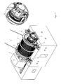
- FIG. 2 shows a drum carrier (1) with a on a main shaft (2) arranged fixed drum (3) and a Lostrommel (4).
- the main shaft (2) is driven by a drive motor (5).
- Both the fixed drum (3) and the Lostrommel (4) each have a disc brake (6,7).
- the delivery drum (4) is detachably connected to the main shaft (2) via a hiding device (8) (see detail A).
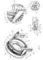
- FIG. 3 Hiding device (8) shown enlarged comprises a with the Lostrommel (4) screwed drum wheel (9), a non-rotatably connected to the main shaft (2) Wellenrad (10) and a slidable in the axial direction Kuppelrad (11). With the Kuppelrad (11) is frontally rotatably connected to a sliding ring (12).
- a switching device (14) for moving the sliding ring (12) in a direction of engagement (15) and in a disengaging direction (16) is arranged fixed to the frame.
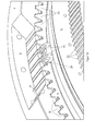
- FIG. 3 combined with FIG. 4 It can be seen that the drum wheel (9) evenly distributed over its circumference Passages (17) by means of screws (18) with the Lostrommel (4) is screwed.
- the drum wheel (9) has an internal toothing (19), which is designed as involute toothing.
- One of the tooth flanks (19a) of all the teeth of the internal toothing (19) is displaced circumferentially in order to ensure sufficient clearance (21) between the teeth of the internal toothing (19) of the drum wheel (9) and the teeth of an external toothing (20) of the toothed wheel (FIG. 11).
- the external toothing (20) of the coupling wheel (11) is also designed as involute toothing.
- the Kuppelrad (11) also has an internal toothing (22).
- the internal toothing (22) of the coupling wheel (11) is axially displaceable in the engagement and disengagement (15,16) on an external toothing (23) of the shaft wheel (10).
- the teeth of Kuppelrad (11) and Wellenrad (10) are designed as trapezoidal gears.
- the Kuppelrad (11) connects in the in FIG. 6a shown, engaged state, frictionally the drum wheel (9) via the shaft wheel (10) with the main shaft (2).
- the sliding ring (12) also has an internal toothing (24), which is also designed as a trapezoidal toothing and axially in the engagement and disengagement (15,16) on the outer toothing (23) of the shaft wheel (10) is displaceable.
- the teeth of the internal teeth (19) of the drum wheel (9) all have a circumferentially extending groove (25) extending between the tooth flanks (19a, b) of each tooth.
- Each groove (25) is laterally bounded on the one hand by a part (26) of a tooth of the internal toothing (19) protruding when the coupling wheel (11) is engaged and on the other hand by an engaging part (28) of a tooth of the internal toothing (19).
- the protruding part (26) has a tooth height (27) which is less than the tooth height (27) of the engaged part (28) of the tooth.
- each pawl (29) has two blocking bodies (31) which project slightly beyond the tooth flanks (20a) of the outer toothing (20) of the coupling wheel (11) in the circumferential direction.
- the tooth flanks (20a) are the tooth flanks which bear against the tooth flank (19a) of the drum wheel (9) under the load of the torque applied by the delivery drum (4) to the main shaft (2).
- each pawl (29) extending in the circumferential direction of the coupling wheel (11) formed integrally with the two locking bodies (31) stop (33) against which after complete engagement of the coupling wheel (11) the end face (34 ) of the engaging part (28) of a tooth of the internal toothing (19) of the drum wheel (9) comes into abutment (see in particular FIG. 6a ).
- the tooth height (27) of the projecting part (26) is determined so that when axial displacement of the coupling wheel (11) in the direction of engagement (15) only the end face (34), but not the Front side of the protruding part (26) on the stop surface (33) abuts.
- Each pawl (29) is backed by a filler (32 a) and a reinforcing bar (32 b), which are bolted together with the pawl (29) on the rear end face (30) of the external toothing (20).
- the filler piece (32a) tightly clamps the pawl (29) to prevent bending and bridges the distance to the reinforcing bar (32b) located outside the internal teeth (19) of the drum wheel (9) with fully engaged cup wheel (11).
- the reinforcement bar (32b) holds the pawl (29) in position and absorbs the forces when the hydraulic cylinders (37a, b) travel at full load against the stop (33) or when the coupling wheel (12) wishes to move axially in the release direction ,
- the reinforcement bar (32b) ensures that each pawl (29) and thus each locking body (31) engaging in the groove (25) is subjected to shear only.
- the sliding ring (12) surrounds an annular collar (12 a) on the closer in the following with reference to FIG. 3 explained switching device (14) acts.
- the switching device (14) comprises two brackets (36a, b) which are fixedly connected to a foundation of the drum carrier (1).
- a hydraulic cylinder (37a, b) At each console (36a, b) is in each case a hydraulic cylinder (37a, b) with a collar (12a) of the sliding ring (12) embracing claw (38) hingedly connected.
- the claw (38) consists of a flange plate (39) for the articulation of the piston rod and a counter-plate (40) arranged at a parallel distance from the flange plate (39).
- a wear spacer (41) as a radial stop for the annular collar (12a) and two on the side edges of the annular collar (12a) fitting Schlberichtplatten (42).
- Both the wear spacer (41) and the wear plates (42) are made of brass, for example.
- the claw (38) emerges laterally into a groove (43) of a guide element (46) which is displaceable on a side wall (45) of the bracket (36a, b) in the direction of engagement and disengagement (15, 16).
- the two claws (38) are connected to one another via an annular frame element (44).
- the connection is made by means of through-bolts which pass through the flange plate (39), the counter-plate (40), the wear spacer (41), the wear plates (42) and the frame element (44).
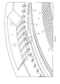
- FIG. 5a shows the decoupled from the main shaft (2) drum wheel (9) which is fixed on the disc brake (7) of the Lostrommel (4).
- the teeth of the external toothing (20) of the coupling wheel (11) are aligned with the interdental spaces of the internal toothing (19) of the drum wheel (9), as shown in FIG FIG. 5a is recognizable.
- the hydraulic cylinders (37a, b) of the switching device (14) are acted upon so that the coupling wheel (11) is axially displaced in the direction of engagement (15) until the external toothing (20) of the coupling wheel (11) is fully engaged with the internal toothing (11).
- 19) of the drum wheel (9) stands, as is made FIG. 5d is recognizable.
- each stopper body (31) extends in extension of one of the circumferentially extending grooves (25) lies.
- the disc brake (7) of the Lostrommel (4) is released, whereby the Trommelrad (9) opposite the Kuppelrad (11) in the counterclockwise direction due to the Lostrommel (4) applied torque twisted.
- each blocking body (31) enters one of the grooves (25) in the teeth of the internal toothing (19), as in FIG FIG. 5e shown.
- the Lostrommel (4) thus coupled with the hiding device (8) can now be rotated via the main shaft (2) together with the fixed drum (3).
- the risk of wandering of the coupling wheel (12) in or against the disengaging direction is effectively prevented by the blocking body (31), which is engaged independently of the direction of rotation of the main shaft (2).
- the take-off drum (4) is first fixed again with the disk brake (7) before disengaging the coupling wheel (11).
- the coupling wheel (11) With the aid of both sides acted upon hydraulic cylinder (37a, b) moved so far until the external teeth (20) of the coupling wheel (11) is out of engagement with the internal teeth (19) of the drum wheel (9).
Landscapes
- Engineering & Computer Science (AREA)
- General Engineering & Computer Science (AREA)
- Mechanical Engineering (AREA)
- Braking Arrangements (AREA)
Description
- Die Erfindung betrifft eine Trommelfördermaschine mit einer angetriebenen Hauptwelle, mindestens einer auf der Hauptwelle angeordneten Lostrommel mit einer Feststellbremse, einer Versteckvorrichtung zur lösbaren Verbindung von Lostrommel und Hauptwelle, die ein mit der Lostrommel drehfest verbundenes Trommelrad mit einer Innenverzahnung, ein mit der Hauptwelle drehfest verbundenes Wellenrad mit einer Außenverzahnung, ein Kuppelrad mit einer Außen- und einer Innenverzahnung, die axial in einer Einrück- und einer Ausrückrichtung auf der Außenverzahnung des Wellenrades verschiebbar ist, einen mit dem Kuppelrad stirnseitig drehfest verbundenen Schiebering und ein gestellfest an der Trommelfördermaschine angeordnete Schaltvorrichtung zum Verschieben des Schieberings in einer Einrück- und Ausrückrichtung, aufweist, wobei die Außenverzahnung des Kuppelrades durch die axiale Verschiebung in Einrückrichtung in Eingriff und durch die axiale Verschiebung in Ausrückrichtung außer Eingriff mit der Innenverzahnung des Trommelrades bringbar ist. Außerdem betrifft die Erfindung ein Verfahren zum Ein- bzw. Ausrücken einer Versteckvorrichtung einer solchen Trommelfördermaschine gemäß dem Oberbegriff des Anspruchs 12 bzw. 13.
- Bei einer Trommelfördermaschine wird als Seilträger eine Seiltrommel verwendet, auf der das Förderseil auf- oder abgewickelt wird. Man unterscheidet Einzeltrommelmaschinen und Doppeltrommelmaschinen. Doppeltrommelmaschinen können beispielsweise als Blairmaschinen oder Bobinen ausgeführt werden. Doppeltrommelmaschinen gibt es sowohl mit einer Festtrommel und einer Lostrommel, als auch mit zwei Lostrommeln. Dabei werden die Lostrommeln über eine schaltbare Kupplung, die Versteckvorrichtung, lösbar mit der Hauptwelle verbunden. Für jede Lostrommel der Trommelfördermaschine ist es erforderlich, dass zum Verstecken eine separate Bremse für die Lostrommel vorhanden ist.
- Die Wickelrichtung des Seils auf den Trommeln der Doppeltrommelmaschine ist gegenläufig, so dass bei gleicher Drehrichtung der Hauptwelle das Seil der einen Trommel aufgewickelt und das andere abgewickelt wird.
- Mit Hilfe der Versteckvorrichtung können beide Trommeln relativ zueinander in Umfangsrichtung versetzt werden. Hierzu wird die Lostrommel mit der ihr zugeordneten Bremse blockiert und von der weiteren Trommel, insbesondere einer Festtrommel, abgekuppelt. Dadurch dreht sich die Lostrommel beim Positionieren des zweiten Fördermittels mit Hilfe der weiteren Trommel nicht mit. Nachdem das zweite Fördermittel an der gewünschten Stelle positioniert ist, wird die Lostrommel wieder mit der Antriebswelle gekuppelt und die Bremse gelöst. Doppeltrommelfördermaschinen mit Versteckvorrichtungen ermöglichen daher die Förderung aus unterschiedlichen Tiefen, so dass beispielsweise ein Fördermittel unter Tage beladen, während gleichzeitig das andere über Tage entladen wird. Diese Funktion ist insbesondere beim Abteufen eines Schachtes wichtig, da sich hier die Teufe des Schachtes permanent ändert, um beispielsweise Abraum zu fördern oder während des Abteufens im Schacht Arbeiten zu verrichten. Dabei wird besonderer Wert auf einen schnellen Versteckvorgang mit hoher Sicherheit in Funktion, Betrieb sowie Verfügbarkeit gelegt.
- Der Stand der Technik einer Versteckvorrichtung für eine von der Firma Gutehoffnungshütte, Aktienverein für Bergbau und Hüttenbetrieb (kurz GHH) gelieferte Trommelmaschine aus dem Jahr 1987 wird anhand des Teilschnitts durch eine Versteckvorrichtung anhand von
Figur 1 näher erläutert. (Die in der Beschreibung des Standes der Technik vorkommenden Bezugszeichen beziehen sich ausschließlich aufFigur 1 .) Ein innen verzahntes Trommelrad (1) ist mit einem nicht dargestellten Seitenschild einer nicht dargestellten Lostrommel verschraubt. Ein Wellenrad (2) ist, wie auch die nicht dargestellte Festtrommel, über Flansche drehfest mit der nicht dargestellten Hauptwelle verschraubt. Auf der Außenverzahnung (4) des Wellenrades (2) sind axial verschiebbar ein Kuppelrad (5), ein Schiebering (6) und ein als Schaltring (7) ausgeführtes Schaltglied angeordnet. Der Schaltring (7) ist gestellfest auf mit dem Fundament der Doppeltrommelmaschine verbundenen Konsolen für die nicht dargestellten hydraulischen Verschiebezylinder verbunden. Der Schaltring (7) gleitet in einer umlaufenden Nut (8) des Schieberings (6), während sich die nicht dargestellte Lostrommel im eingekuppelten Zustand der Versteckvorrichtung dreht. Das Ein- und Ausrücken der Versteckvorrichtung erfolgt im durch Bremsen gesicherten Stillstand der Doppeltrommelmaschine. Dabei sichern die hydraulischen Verschiebezylinder die Position des axial in der Einrück- und Ausrückrichtung auf der Außenverzahnung (4) des Wellenrades (3) verschiebbaren Kuppelrades (5). - Im Betrieb der bekannten Versteckvorrichtung für eine Doppeltrommelfördermaschine ist bei dem Großteil der Doppeltrommelfördermaschinen das Problem aufgetreten, dass sich das Kuppelrad (5) während der Drehung und Förderung mit der Lostrommel in Ausrückrichtung bewegte, wodurch auf die hydraulischen Verschiebezylinder und auf den stirnseitig mit Gleitmetall (9) versehenen Schaltring (7) erhebliche Kräfte ausgeübt wurden. In folge dessen versagte durch Überhitzung die Fettschmierung zwischen der Nut (8) des Schieberings (6) und dem Gleitmetall (9) und anschließend schmolz das Gleitmetall (9). Der Grund für dieses Ausrücken des Kuppelrades (5) unter Last der Lostrommel bei diesen Doppeltrommelfördermaschinen konnte nie ermittelt werden. Ein möglicher Erklärungsansatz waren Walkbewegungen des Seitenschildes an dem Trommelrad.
- Um die Bewegung in Ausrückrichtung unter Last der Lostrommel zu vermeiden, wurden nachträglich Schrauben oder Bolzen auf dem Wellenrad (2) montiert, die eine axiale Verschiebung des Kuppelrades verhinderten. Der Versteckvorgang erfordert daher, dass ein Schlosser die nachträglich montierten Schrauben oder Bolzen zunächst aufwendig entfernt, und endet damit, dass der Schlosser die Elemente anschließend wieder anbringt. Derartige Montageschritte sind für den Betrieb einer Trommelfördermaschine mit Versteckvorrichtung insbesondere im Teufbetreib mit häufigen Versteckvorgängen nicht akzeptabel.
- Die
DE 922 194 B offenbart eine Trommelfördermaschine mit einer Versteckvorrichtung, bei der eine mit einer Bremse versehene Lostrommel mit einer angetriebenen Hauptwelle koppelbar ist. Auf einem genuteten Teil der Antriebswelle ist eine Verschiebemuffe mit einer Außenverzahnung als Kuppeleinrichtung angebracht. Die Außenverzahnung kann durch Verschiebung der Verschiebmuffe in Achsrichtung der Antriebswelle mit einer Innenverzahnung eines drehfest mit der Lostrommel verbundenen Zwischenteils in und außer Eingriff gebracht werden. Die Verschiebung der Verschiebmuffe erfolgt mit einer an der Trommelwelle angebauten Bewegungseinrichtung. - Ausgehend von diesem Stand der Technik liegt der Erfindung daher die Aufgabe zu Grunde, eine Trommelfördermaschine zu schaffen, deren Versteckvorrichtung ohne Montage zusätzlicher Elemente wirksam ein ungewolltes Ausrücken des Kuppelrades der Versteckvorrichtung, insbesondere unter Last der Lostrommel, verhindert.
- Diese Aufgabe wird mit einer Vorrichtung gemäß den Merkmalen des Anspruchs 1 sowie mit einem Verfahren gemäß den Merkmalen des Anspruchs 12 bzw. 13 gelöst.
- Die Lösung dieser Aufgabe macht sich den Umstand zu nutze, dass obwohl der Antrieb der Trommelfördermaschine rechts- oder linksdrehende Momente aufbringen muss, sich die Richtung des von jeder einzelnen Trommel auf die Hauptwelle aufgebrauchten Drehmomentes nicht ändert, wohl aber die Höhe abhängig von der Teufe und Beladung. Im Einzelnen wird die Aufgabe bei einer Trommelfördermaschine der eingangs erwähnten Art dadurch gelöst, dass an dem Kuppelrad mindestens ein Sperrkörper befestigt ist, die Zähne der Innenverzahnung des Trommelrades eine in Umfangsrichtung des Trommelrades verlaufende Nut zur Aufnahme des Sperrkörpers aufweisen, zwischen den Zähnen der Innenverzahnung des Trommelrades und den Zähnen der Außenverzahnung des Kuppelrades ein Spiel besteht, so dass durch Verdrehen des eingerückten Kuppelrades gegenüber dem Trommelrad um den Betrag des Spiels jeder Sperrkörper in eine der Nuten in - und außer Eingriff bringbar ist.
- Das von der Lostrommel auf die Hauptwelle übertragene Drehmoment hält die Sperrkörper des eingerückten Kuppelrades sicher in ihrer in der Nut eingerasteten Position. Das Spiel zwischen den Zähnen der Innenverzahnung des Trommelrades und den Zähnen der Außenverzahnung des Kuppelrades wird dadurch hervorgerufen, dass bei der Innenverzahnung des Trommelrades die Zahnflanken einseitig in Umfangsrichtung verschoben sind. Hierdurch entsteht zu den Zähnen der Außenverzahnung des Kuppelrades ein ausreichendes Spiel, so dass durch Verdrehen des eingerückten Kuppelrades gegenüber dem Trommelrad um den Betrag des Spiels jeder Sperrkörper in eine der Nuten In- und Außereingriff bringbar ist.
- Die in die Nuten in Eingriff bringbaren Sperrkörper verhindern wirksam ein Verschieben des Kuppelrades axial in beide Richtungen. Damit wird nicht nur der bisher beobachtete Effekt eines ungewollten Ausrückens des Kuppelrades verhindert, sondern auch eine ungewollte gegenläufige Bewegung des Kuppelrades in Einrückrichtung. Dies würde in gleicher Weise das Fett verbrennen und das Gleitmetall zum Schmelzen bringen.
- Der Sperrkörper ist insbesondere an der in Einrückrichtung des Kuppelrades hinteren Stirnseite von einem der Zähne der Außenverzahnung des Kuppelrades angeordnet. Die Anordnung des Sperrkörpers an der Stirnseite erlaubt eine Nachrüstung bestehender Trommelfördermaschinen mit der Versteckvorrichtung.
- Jeder Sperrkörper ragt über eine der beiden Zahnflanken von einem der Zähne der Außenverzahnung des Kuppelrades hinaus, wobei es sich um die Zahnflanke handelt, die unter der Last des von der Lostrommel auf die Hauptwelle aufgebrachten Drehmomentes an einer Zahnflanke des Trommelrades anliegt. Anstelle an der Stirnseite kann der Sperrkörper auch an der Zahnflanke selbst angeordnet sein und sich von der Oberfläche der Zahnflanke in den Zahnzwischenraum erstrecken.
- Über den Umfang des Kuppelrades sind abhängig von der Zähnezahl und Last vorzugsweise mehrere Sperrkörper an den Stirnseiten der Zähne der Außenverzahnung des Kuppelrades angeschraubt.
- Der Sperrkörper ist insbesondere als Platte ausgeführt und steht in Umfangsrichtung etwas über die Zahnflanke über. Durch Verdrehen des Kuppelrades rastet er in die vorgesehene Nut ein.
- Um den Verschiebeweg des Kuppelrades in Einrückrichtung zu begrenzen, weist die Trommelfördermaschine mindestens einen Anschlag auf. Der Anschlag wird so positioniert, dass beim Anschlagen des Kuppelrades jeder Sperrkörper in Verlängerung einer der in Umfangsrichtung verlaufenden Nuten liegt. Konstruktiv vorteilhaft ist der Anschlag an dem Kuppelrad befestigt und weist eine Anschlagfläche für einen Zahn der Innenverzahnung des Trommelrades auf.
- In besonders vorteilhafter Ausgestaltung der Erfindung sind der Anschlag und mindestens ein Sperrkörper, vorzugsweise jedoch zwei Sperrkörper einstückig zu einer Sperrklinke miteinander verbunden. Die Sperrklinken sind vorzugsweise so ausgebildet, dass sie ohne Änderung der Konstruktion auch so montiert werden können, dass die Sperrkörper auch bei anderer Drehrichtung des Trommelrades einrasten. Die Versteckvorrichtung ist, sofern derartige Sperrklinken verwendet werden, für beide Momentenrichtungen konzipiert. Das vermeidet Fehler in der Herstellung und macht die Bauteile unabhängig von der Richtung des Drehmomentes einer Trommel.
- Eine automatische präzise Positionierung des Sperrkörpers in Verlängerung der Nut wird erreicht, wenn eine Seitenwand der Nut mit der Anschlagfläche des Anschlags zusammenwirkt. Dieses Zusammenwirken wird vorzugsweise dadurch bewirkt, dass ein bei eingerücktem Kuppelrad überstehender Teil jedes Zahns der Innenverzahnung des Trommelrades ein geringere Zahnhöhe aufweist als der in Eingriff stehende Teil jedes Zahns der Innenverzahnung des Trommelrades, in dem überstehenden Teil die Nut verläuft und die Zahnhöhe des überstehenden Teils so bestimmt ist, dass bei axialer Verschiebung des Kuppelrades in Einrückrichtung ausschließlich die Stirnseite des in Eingriff stehenden Teils des Zahns an der Anschlagfläche zur Anlage gelangt.
- Um den Sperrkörper in Position zu halten und die Kräfte aufzunehmen, wenn die Hydraulikzylinder mit voller Last den Anschlag gegen die Zähne des Trommelrades fahren, ist der Sperrkörper in vorteilhafter Ausgestaltung der Erfindung mit einem an dem Kuppelrad befestigten Verstärkungselement verbunden. Zwischen dem Verstärkungselement und dem Sperrkörper kann darüber hinaus ein Füllstück angeordnet sein, um die Distanz zum Verstärkungselement zu überbrücken. Das Füllstück und das Verstärkungselement können auch einteilig ausgeführt sein.
- Um eine gute Führung des Kuppelrades bei der axialen Verschiebung zu erreichen, ist nicht nur das Kuppelrad, sondern darüber hinaus der Schiebering innen verzahnt. Die Länge der Verzahnung von Kuppelrad und Schiebering gewährleisten, dass eine sichere axiale Führung ohne Verklemmen stattfindet.
- Kuppelrad und Schiebering sind aus produktionstechnischen Gründen vorzugsweise als separate Bauteile ausgeführt, die drehfest miteinander verbunden sind. Das Kuppelrad und der Schiebering können jedoch auch einteilig ausgeführt sein.
- Die Innenverzahnungen von Kuppelrad und Schiebering sind im Interesse einer guten Führung vorzugsweise als Trapezverzahnung ausgeführt. Die Außenverzahnung des Kuppelrades sowie die mit dem Kuppelrad kämmende Innenverzahnung des Trommelrades sind vorzugsweise als Evolventenverzahnung ausgeführt.
- Um den Schiebering sowie das damit verbundene Kuppelrad in Einrück- bzw. Ausrückrichtung mit Hilfe des Schaltgliedes bewegen zu können, ist der Schiebering in vorteilhafter Ausgestaltung der Erfindung mit einem ringförmigen Bund versehen, der drehfest mit dem Schiebering verbunden ist. Das Schaltglied umfasst mindestens einen, vorzugsweise zwei Hydraulikzylinder, deren Kolbenstange jeweils endseitig mit einer den Bund umgreifenden Klaue versehen ist. Um die Klauen zu führen und zu positionieren, sind diese vorzugsweise über ein Rahmenelement miteinander verbunden. Das Rahmenelement kann insbesondere ringförmig ausgebildet sein, wobei der Ring mit dem das Kuppelrad umgebenden Bund fluchtet. Zwischen dem ringförmigen Rahmenelement und dem Bund sind vorzugsweise austauschbare Verschleißelemente angeordnet. Die Verzahnung des Wellenrades ist so lang ausgebildet, daß das Kuppelrad und der Schiebering ohne zu verklemmen auch mit nur einem Zylinder betrieben werden können. Dies ist wichtig, falls ein Zylinder schwergängig sein oder werden sollte.
- Nachfolgend wird die Erfindung anhand der Figuren näher erläutert. Es zeigen:
- Figur 2
- eine perspektivische Gesamtansicht einer Doppeltrommelfördermaschine mit einer Versteckvorrichtung,
- Figur 3
- eine perspektivische Darstellung der Versteckvorrichtung,
- Figur 4
- eine perspektivische Teildarstellung eines Trommel-, Kuppel- und Wellenrades der Versteckvorrichtung nach
Figur 3 , - Figuren 5 a-c
- die Versteckvorrichtung während des Einrückens des Kuppelrades,
- Figur 5 d
- die Versteckvorrichtung mit vollständig eingerücktem Kuppelrad,
- Figur 5 e
- die Versteckvorrichtung mit vollständig eingerücktem Kuppelrad in verriegeltem Zustand,
- Figur 5 f
- die Versteckvorrichtung mit vollständig eingerücktem Kuppelrad in entriegeltem Zustand,
- Figur 5 g
- die Versteckvorrichtung mit vollständig ausgerücktem Kuppelrad,
- Figur 6 a
- einen Teilschnitt durch eine Versteckvorrichtung mit eingerücktem Kuppelrad sowie
- Figur 6 b
- einen Teilschnitt durch eine Versteckvorrichtung mit ausgerücktem Kuppelrad.
-
Figur 2 zeigt eine Trommelfördermaschine (1) mit einer auf einer Hauptwelle (2) angeordneten Festtrommel (3) und einer Lostrommel (4). Die Hauptwelle (2) wird von einem Antriebsmotor (5) angetrieben. - Sowohl die Festtrommel (3) als auch die Lostrommel (4) weisen jeweils eine Scheibenbremse (6,7) auf. Die Lostrommel (4) ist über eine Versteckvorrichtung (8) (vgl. Detail A) lösbar mit der Hauptwelle (2) verbunden.
- Die in
Figur 3 vergrößert dargestellte Versteckvorrichtung (8) umfasst ein mit der Lostrommel (4) verschraubtes Trommelrad (9), ein mit der Hauptwelle (2) drehfest verbundenes Wellenrad (10) sowie ein in axialer Richtung verschiebbares Kuppelrad (11). Mit dem Kuppelrad (11) ist stirnseitig drehfest ein Schiebering (12) verbunden. - An der Trommelfördermaschine (1) ist gestellfest eine Schaltvorrichtung (14) zum Verschieben des Schieberings (12) in einer Einrückrichtung (15) und in einer Ausrückrichtung (16) angeordnet.
- Aus
Figur 3 in Verbindung mitFigur 4 ist erkennbar, dass das Trommelrad (9) durch über seinen Umfang gleichmäßig verteilte Durchgänge (17) mittels Schrauben (18) mit der Lostrommel (4) verschraubt ist. - Wie insbesondere aus den
Figuren 6a ,b erkennbar, weist das Trommelrad (9) eine Innenverzahnung (19) auf, die als Evolventenverzahnung ausgeführt ist. Eine der Zahnflanken (19a) sämtlicher Zähne der Innenverzahnung (19) ist auf dem Umfang verschoben, um ein ausreichendes Spiel (21) zwischen den Zähnen der Innenverzahnung (19) des Trommelrades (9) und den Zähnen einer Außenverzahnung (20) des Kuppelrades (11) zu schaffen. Dieses Spiel (21), wie es insbesondere aus denFiguren 5b ,c erkennbar ist, ist für das Verriegeln der Versteckvorrichtung (8) erforderlich. - Die Außenverzahnung (20) des Kuppelrades (11) ist ebenfalls als Evolventenverzahnung ausgeführt. Das Kuppelrad (11) weist darüber hinaus eine Innenverzahnung (22) auf. Die Innenverzahnung (22) des Kuppelrades (11) ist axial in Einrück- und Ausrückrichtung (15,16) auf einer Außenverzahnung (23) des Wellenrades (10) verschiebbar. Die Verzahnungen von Kuppelrad (11) und Wellenrad (10) sind als Trapezverzahnungen ausgeführt. Das Kuppelrad (11) verbindet in dem in
Figur 6a dargestellten, eingerückten Zustand, kraftschlüssig das Trommelrad (9) über das Wellenrad (10) mit der Hauptwelle (2). - Der Schiebering (12) weist ebenfalls eine Innenverzahnung (24) auf, die ebenfalls als Trapezverzahnung ausgeführt und axial in Einrück- und Ausrückrichtung (15,16) auf der Außenverzahnung (23) des Wellenrades (10) verschiebbar ist.
- Das Wellenrad (10) sowie dessen Außenverzahnung (23) ist in Einrück- bzw. Ausrückrichtung (15,16) so lang, dass das Kuppelrad (11) mit dem Schiebering (12) bis zum vollständigen Ausrücken des Kuppelrades (11) geführt sind.
- Die Zähne der Innenverzahnung (19) des Trommelrades (9) weisen sämtlich eine in Umfangsrichtung verlaufende Nut (25) auf, die sich zwischen den Zahnflanken (19a,b) jedes Zahnes erstreckt.
- Jede Nut (25) wird seitlich einerseits durch ein bei eingerücktem Kuppelrad (11) überstehendes Teil (26) eines Zahns der Innenverzahnung (19) und andererseits ein in Eingriff stehendes Teil (28) eines Zahns der Innenverzahnung (19) begrenzt. Das überstehende Teil (26) weist eine Zahnhöhe (27) auf, die geringer ist als die Zahnhöhe (27) des in Eingriff stehenden Teils (28) des Zahns.
- Wie insbesondere aus
Figur 3 in Verbindung mitFiguren 5 a - g erkennbar sind am Umfang des Kuppelrades (11) mehrere Sperrklinken (29) an der in Einrückrichtung (15) des Kuppelrades (11) hinteren Stirnseite der Zähne der Außenverzahnung (20) angeschraubt. Jede Sperrklinke (29) weist zwei Sperrkörper (31) auf, die in Umfangsrichtung geringfügig über die Zahnflanken (20a) der Außenverzahnung (20) des Kuppelrades (11) hinausragen. Bei den Zahnflanken (20a) handelt es sich um die Zahnflanken, die unter der Last des von der Lostrommel (4) auf die Hauptwelle (2) aufgebrachten Drehmoments an den Zahnflanke (19a) des Trommelrades (9) anliegen. Zwischen den beiden Sperrkörpern (31) jeder Sperrklinke (29) erstreckt sich in Umfangsrichtung des Kuppelrades (11) ein einstückig mit den beiden Sperrkörpern (31) ausgebildeter Anschlag (33), gegen den nach vollständigem Einrücken des Kuppelrades (11) die Stirnseite (34) des in Eingriff stehenden Teils (28) eines Zahns der Innenverzahnung (19) des Trommelrades (9) zur Anlage gelangt (vgl. insbesondereFigur 6a ). Die Zahnhöhe (27) des überstehenden Teils (26) ist dabei so bestimmt, dass bei axialer Verschiebung des Kuppelrades (11) in Einrückrichtung (15) ausschließlich die Stirnseite (34), nicht jedoch die Stirnseite des überstehenden Teils (26) an der Anschlagfläche (33) anstößt. - Jede Sperrklinke (29) wird von einem Füllstück (32a) und einem Verstärkungsriegel (32b) hinterlegt, die zusammen mit der Sperrklinke (29) an der hinteren Stirnseite (30)der Außenverzahnung (20) verschraubt werden. Das Füllstück (32a) spannt die Sperrklinke (29) fest, um Biegungen zu verhindern und überbrückt die Distanz zum Verstärkungsriegel (32b), der außerhalb der Innenverzahnung (19) des Trommelrades(9) bei voll eingerücktem Kuppelrad (11) liegt. Der Verstärkungsriegel (32b) hält die Sperrklinke (29) in Position und nimmt die Kräfte auf, wenn die Hydraulikzylinder (37a, b) mit voller Last an den Anschlag (33) fahren oder wenn sich das Kuppelrad (12) in Ausrückrichtung axial bewegen will. Der Verstärkungsriegel (32b) stellt sicher, dass jede Sperrklinke (29) und damit jeder in die Nut (25) eingreifende Sperrkörper (31) ausschließlich auf Scherung beansprucht wird.
- Den Schiebering (12) umgibt ein ringförmiger Bund (12a) auf den die nachfolgend näher anhand der
Figur 3 erläuterte Schaltvorrichtung (14) einwirkt. Die Schaltvorrichtung (14) umfasst zwei Konsolen (36a,b), die mit einem Fundament der Trommelfördermaschine (1) fest verbunden sind. An jeder Konsole (36a,b) ist jeweils ein Hydraulikzylinder (37a,b) mit einer den Bund (12a) des Schieberings (12) umgreifenden Klaue (38) gelenkig verbunden. Die Klaue (38) besteht aus einem Flanschblech (39) zur Anlenkung der Kolbenstange und einem im parallelen Abstand zu dem Flanschblech (39) angeordneten Gegenblech (40). Zwischen den beiden Blechen (39,40) befindet sich ein Schleißdistanzstück (41) als radialer Anschlag für den ringförmigen Bund (12a) sowie zwei an den Seitenrändern des ringförmigen Bundes (12a) anliegende Schleißplatten (42). Sowohl das Schleißdistanzstück (41) als auch die Schleißplatten (42) bestehen beispielsweise aus Messing. - Die Klaue (38) taucht seitlich in eine Nut (43) eines an einer Seitenwange (45) der Konsole (36a,b) in Ein- und Ausrückrichtung (15, 16) verschieblichen Führungselementes (46) ein. Um ein Auswandern der Klauen (38) zu verhindern, sind die beiden Klauen (38) über ein ringförmiges Rahmenelement (44) miteinander verbunden. Die Verbindung erfolgt mit Hilfe von Durchgangsschrauben, die das Flanschblech (39), das Gegenblech (40), das Schleißdistanzstück (41), die Schleißplatten (42) und das Rahmenelement (44) durchsetzen.
- Nachfolgend wird die Betriebsweise der Versteckvorrichtung (8) der Trommelfördermaschine (1) anhand der
Figuren 5a - 5g erläutert. -
Figur 5a zeigt das von der Hauptwelle (2) entkoppelte Trommelrad (9), das über die Scheibenbremse (7) der Lostrommel (4) festgesetzt ist. Mit Hilfe des Antriebsmotors (5) werden die Zähne der Außenverzahnung (20) des Kuppelrades (11) fluchtend zu den Zahnzwischenräumen der Innenverzahnung (19) des Trommelrades (9) ausgerichtet, wie dies inFigur 5a erkennbar ist. Anschließend werden die Hydraulikzylinder (37a, b) der Schaltvorrichtung (14) beaufschlagt, so dass das Kuppelrad (11) axial in Einrückrichtung (15) verschoben wird, bis die Außenverzahnung (20) des Kuppelrades (11) vollständig in Eingriff mit der Innenverzahnung (19) des Trommelrades (9) steht, wie dies ausFigur 5d erkennbar ist. Zu diesem Zeitpunkt schlägt die Stirnseite (34) der Innenverzahnung (19) des Trommelrades (9) an dem Anschlag (33) der Sperrklinke (29) an, wodurch gewährleistet wird, dass jeder Sperrkörper (31) in Verlängerung einer der in Umfangsrichtung verlaufenden Nuten (25) liegt. Nunmehr wird die Scheibenbremse (7) der Lostrommel (4) gelöst, wodurch sich das Trommelrad (9) gegenüber dem Kuppelrad (11) im Gegenuhrzeigersinn aufgrund des von der Lostrommel (4) aufgebrachten Drehmomentes verdreht. Durch diese Verdrehung gelangt jeder Sperrkörper (31) in eine der Nuten (25) in den Zähnen der Innenverzahnung (19), wie inFigur 5e dargestellt. - Die derart mit der Versteckvorrichtung (8) gekuppelte Lostrommel (4) kann nunmehr über die Hauptwelle (2) zusammen mit der Festtrommel (3) in Drehung versetzt werden. Die Gefahr eines Wanderns des Kuppelrades (12) in oder entgegen der Ausrückrichtung wird durch die unabhängig von der Drehrichtung der Hauptwelle (2) in Eingriff befindlichen Sperrkörper (31) wirksam verhindert.
- Soll nun die Lostrommel (4) ausgekuppelt werden, wird vor dem Auskuppeln des Kuppelrades (11) die Lostrommel (4) zunächst mit der Scheibenbremse (7) wieder festgesetzt. Durch Verdrehen des eingerückten Kuppelrades (11) gegenüber dem nunmehr festgesetzten Trommelrad (9) im Gegenuhrzeigersinn mit Hilfe des Antriebsmotors (5) um den Betrag des Spiels (21) wird jeder Sperrkörper (31) außer Eingriff gebracht, wie dies in
Figur 5f erkennbar ist. Anschließend wird das Kuppelrad (11) mit Hilfe der beidseitig beaufschlagbaren Hydraulikzylinder(37a, b) soweit verschoben, bis die Außenverzahnung (20) des Kuppelrades (11) außer Eingriff mit der Innenverzahnung (19) des Trommelrades (9) steht. Sodann wird zum weiteren Betrieb ausschließlich der Festtrommel (3) die Hauptwelle (2) in Drehung versetzt, während die entkoppelte Lostrommel von der Bremseinrichtung (7) festgehalten wird.Bezugszeichenliste Nr. Bezeichnung Nr. Bezeichnung 1 Trommelfördermaschine 29 Sperrklinken 2 Hauptwelle 30 hintere Stirnseite Pos fehlt in Figuren 3 Festtrommel 31 Sperrkörper =29 ?? 4 Lostrommel 32a Füllstück 5 Antriebsmotor 32b Verstärkungsriegel 6 Scheibenbremse 33 Anschlag 7 Scheibenbremse 34 Stirnseite 8 Versteckvorrichtung 35 -- 9 Trommelrad 36a,b Konsole 10 Wellenrad 37a,b Hydraulikzylinder 11 Kuppelrad 38 Klaue 12 Schiebering 39 Flanschblech 12a ringförmiger Bund 40 Gegenblech 13 - 41 Schleißdistanzstück 14 Schaltvorrichtung 42 Schleißplatten 15 Einrückrichtung 43 Nut 16 Ausrückrichtung 44 Rahmenelement 17 Durchgänge 45 Seitenwange 18 Schrauben 46 Führungselement 19 Innenverzahnung (T9) 47 19a,b Zahnflanke 20 Außenverzahnung (K11) 48 20a Zahnflanke 21 Spiel 49 22 Innenverzahnung (K11) 50 23 Außenverzahnung (W11) 51 24 Innenverzahnung (Sch12) 52 25 Nut 53 26 überstehendes Teil 54 27 Zahnhöhe 55 28 im Eingriff stehendes Teil 56
Claims (13)
- Trommelfördermaschine (1) mit einer angetriebenen Hauptwelle (2), mindestens einer auf der Hauptwelle (2) angeordneten Lostrommel (4) mit einer Bremse (7), einer Versteckvorrichtung (8) zur lösbaren Verbindung von Lostrommel (4) und Hauptwelle (2), die- ein mit der Lostrommel (4) drehfest verbundenes Trommelrad (9) mit einer Innenverzahnung (19),- ein mit der Hauptwelle (2) drehfest verbundenes Wellenrad (10) mit einer Außenverzahnung (23),- ein Kuppelrad (11) mit einer Außenverzahnung (20) und einer Innenverzahnung (22), die axial in einer Einrückrichtung (15) und einer Ausrückrichtung (16) auf der Außenverzahnung(23) des Wellenrades (10) verschiebbar ist,- einen mit dem Kuppelrad (11) stirnseitig drehfest verbundenen Schiebering (12) und- ein gestellfest an der Trommelfördermaschine (1) angeordnete Schaltvorrichtung (14) zum Verschieben des Schieberings (12) in Einrück- und Ausrückrichtung (15, 16),aufweist, wobei die Außenverzahnung (20) des Kuppelrades (11) durch die axiale Verschiebung in Einrückrichtung (15) in Eingriff und durch die axiale Verschiebung in Ausrückrichtung (16) außer Eingriff mit der Innenverzahnung (19) des Trommelrades (9) bringbar ist, dadurch gekennzeichnet, dass- an dem Kuppelrad (9) mindestens ein Sperrkörper (31) befestigt ist,- die Zähne der Innenverzahnung (19) des Trommelrades (9) eine in Umfangsrichtung des Trommelrades (9) verlaufende Nut (25) zur Aufnahme des Sperrkörpers (31) aufweisen,- zwischen den Zähnen der Innenverzahnung (19) des Trommelrades (9) und den Zähnen der Außenverzahnung (20) des Kuppelrades (11) ein Spiel (21) besteht, so dass durch Verdrehen des eingerückten Kuppelrades (11) gegenüber dem Trommelrad (9) um den Betrag des Spiels (21) jeder Sperrkörper (31) in eine der Nuten (25) in - und außer Eingriff bringbar ist.
- Trommelfördermaschine nach Anspruch 1, dadurch gekennzeichnet, dass jeder Sperrkörper (31) an der in Einrückrichtung (15) des Kuppelrades (11) hinteren Stirnseite (30) von einem der Zähne der Außenverzahnung (20) des Kuppelrades (11) angeordnet ist.
- Trommelfördermaschine nach Anspruch 1 oder 2, dadurch gekennzeichnet, dass jeder Sperrkörper (31) über eine der beiden Zahnflanken (20a,b) von einem der Zähne der Außenverzahnung (20) des Kuppelrades (11) hinausragt, wobei es sich um die Zahnflanke (20a) handelt, die unter der Last des von der Lostrommel (4) auf die Hauptwelle (2) aufgebrachten Drehmomentes an einer Zahnflanke (19a) des Trommelrades (9) anliegt.
- Trommelfördermaschine nach einem der Ansprüche 1 bis 3, dadurch gekennzeichnet, dass die Trommelfördermaschine (1) mindestens einen Anschlag (33) aufweist, der die axiale Verschieblichkeit des Kuppelrades (11) in Einrückrichtung (15) begrenzt.
- Trommelfördermaschine nach Anspruch 4, dadurch gekennzeichnet, dass der Anschlag (33) an dem Kuppelrad (11) befestigt ist und eine Anschlagfläche für einen Zahn der Innenverzahnung (19) des Trommelrades (9) aufweist.
- Trommelfördermaschine nach Anspruch 4 oder 5, dadurch gekennzeichnet, dass mindestens ein Anschlag (33) und mindestens ein Sperrkörper (31) einstückig ausgebildet sind.
- Trommelfördermaschine nach einem der Ansprüche 4 bis 6, dadurch gekennzeichnet, dass- ein bei eingerücktem Kuppelrad (11) überstehendes Teil (26) jedes Zahns der Innenverzahnung (19) des Trommelrades (9) ein geringere Zahnhöhe (27) aufweist, als der in Eingriff stehende Teil (28) jedes Zahns der Innenverzahnung (19) des Trommelrades (9),- zwischen dem überstehenden Teil (26) und dem in Eingriff stehenden Teil (28) die Nut (25) verläuft und- die Zahnhöhe (27) des überstehenden Teils (26) so bestimmt ist, dass bei axialer Verschiebung des Kuppelrades (11) in Einrückrichtung (15) ausschließlich die Stirnseite (34) des in Eingriff stehenden Teils (28) des Zahns an dem Anschlag (33) zur Anlage gelangt.
- Trommelfördermaschine nach einem der Ansprüche 1 bis 7, dadurch gekennzeichnet, dass der Sperrkörper (31) mit einem an dem Kuppelrad (11) befestigten Verstärkungselement (32b) verbunden ist.
- Trommelfördermaschine nach einem der Ansprüche 1 bis 8, dadurch gekennzeichnet, dass der Schiebering(12) eine Innenverzahnung (24) aufweist, die axial in Einrück- und Ausrückrichtung (15, 16) auf der Außenverzahnung (23) des Wellenrades (10) verschiebbar ist.
- Trommelfördermaschine nach einem der Ansprüche 1 bis 9, dadurch gekennzeichnet, dass den Schiebering (12) ein ringförmiger Bund (12a) umgibt, der drehfest mit dem Schiebring (12) verbunden ist und die Schaltvorrichtung (14) zum Verschieben des Schieberings (12) mindestens einen Hydraulikzylinder (37a, b) umfasst, deren Kolbenstangen jeweils endseitig mit einer den Bund (12a) umgreifenden Klaue (38) versehen sind.
- Trommelfördermaschine nach Anspruch 10, dadurch gekennzeichnet, dass die Klauen (38) durch ein Rahmenelement (44) miteinander verbunden sind.
- Verfahren zum Ausrücken einer Versteckvorrichtung einer Trommelfördermaschine nach Anspruch 1, dadurch gekennzeichnet, dass- vor dem Ausrücken des Kuppelrades (11) die Lostrommel (4) mit einer Bremse (7) festgesetzt wird,- durch Verdrehen des eingerückten Kuppelrades (11) gegenüber dem festgesetzten Trommelrad (9) in Richtung des von der Lostrommel (4) auf die Hauptwelle (2) aufgebrachten Drehmomentes um den Betrag des Spiels (21) jeder Sperrkörper (31) außer Eingriff gebracht wird,- anschließend das Kuppelrad (11) mit Hilfe der Schaltvorrichtung (14) so weit axial in Ausrückrichtung (16) verschoben wird, bis die Außenverzahnung (20) des Kuppelrades (11) außer Eingriff mit der Innenverzahnung (19) des Trommelrades (9) steht und- sodann zum weiteren Betrieb die Hauptwelle (2) in Drehung versetzt wird.
- Verfahren zum Einrücken einer Versteckvorrichtung einer Trommelfördermaschine nach Anspruch 1, dadurch gekennzeichnet, dass- vor dem Einrücken des Kuppelrades (11) die Lostrommel (4) mit einer Bremse (7) festgesetzt wird,- die Zähne der Außenverzahnung (20) des Kuppelrades (11) fluchtend zu den Zahnzwischenräumen der Innenverzahnung (19) des Trommelrades (9) ausgerichtet werden,- anschließend das Kuppelrad (11) mit Hilfe der Schaltvorrichtung (14) so weit axial in Einrückrichtung (15) verschoben wird, bis die Außenverzahnung (20) des Kuppelrades (11) in Eingriff mit der Innenverzahnung (19) des Trommelrades (9) steht und jeder Sperrkörper (31) in Verlängerung einer der in Umfangsrichtung verlaufenden Nuten (25) liegt,- das Trommelrad (9) gegenüber dem Kuppelrad (11) in Richtung des von der Lostrommel (4) auf die Hauptwelle (2) aufgebrachten Drehmomentes um den Betrag des Spiels verdreht wird, wobei jeder Sperrkörper in einer der Nuten in Eingriff gebracht wird und- zum weiteren Betrieb die Hauptwelle in Drehung versetzt wird.
Applications Claiming Priority (2)
| Application Number | Priority Date | Filing Date | Title |
|---|---|---|---|
| DE102012109398A DE102012109398B3 (de) | 2012-10-02 | 2012-10-02 | Trommelfördermaschine mit einer angetriebenen Hauptwelle |
| PCT/EP2013/068997 WO2014053299A1 (de) | 2012-10-02 | 2013-09-13 | Trommelfördermaschine mit einer angetriebenen hauptwelle |
Publications (2)
| Publication Number | Publication Date |
|---|---|
| EP2800719A1 EP2800719A1 (de) | 2014-11-12 |
| EP2800719B1 true EP2800719B1 (de) | 2015-10-14 |
Family
ID=49301436
Family Applications (1)
| Application Number | Title | Priority Date | Filing Date |
|---|---|---|---|
| EP13771410.1A Active EP2800719B1 (de) | 2012-10-02 | 2013-09-13 | Trommelfördermaschine mit einer angetriebenen hauptwelle |
Country Status (6)
| Country | Link |
|---|---|
| US (1) | US9624075B2 (de) |
| EP (1) | EP2800719B1 (de) |
| CA (1) | CA2861699C (de) |
| DE (1) | DE102012109398B3 (de) |
| WO (1) | WO2014053299A1 (de) |
| ZA (1) | ZA201404697B (de) |
Cited By (2)
| Publication number | Priority date | Publication date | Assignee | Title |
|---|---|---|---|---|
| KR20180137491A (ko) * | 2016-04-22 | 2018-12-27 | 섀플러 테크놀로지스 아게 운트 코. 카게 | 트랜스미션의 동기화 장치용 슬라이딩 슬리브 및 슬라이딩 슬리브를 갖는 동기화 장치 |
| DE102019112948B3 (de) * | 2019-05-16 | 2020-09-03 | Olko-Maschinentechnik Gmbh | Doppeltrommelfördermaschine |
Families Citing this family (2)
| Publication number | Priority date | Publication date | Assignee | Title |
|---|---|---|---|---|
| DE102013000830A1 (de) * | 2013-01-18 | 2014-07-24 | Siemag Tecberg Gmbh | Versteckvorrichtung |
| CN116986239B (zh) * | 2023-09-27 | 2024-01-23 | 四川鑫业纸业有限公司 | 具有快拆结构的滚筒输送机及其使用方法 |
Family Cites Families (16)
| Publication number | Priority date | Publication date | Assignee | Title |
|---|---|---|---|---|
| DE922194C (de) * | 1951-12-09 | 1955-01-10 | Demag Ag | Trommelfoerdermaschine mit Versteckvorrichtung |
| US3411751A (en) * | 1967-04-20 | 1968-11-19 | Frank D. Pooley Jr. | Hydraulic power winch |
| US3563353A (en) * | 1968-06-27 | 1971-02-16 | United Parcel Service General | Automatic reversing clutches with pilot brake |
| US3589243A (en) * | 1969-03-17 | 1971-06-29 | Spencer Bowman | Hydraulic drive system |
| CH544895A (de) * | 1970-11-25 | 1973-11-30 | Maag Zahnraeder & Maschinen Ag | Zahnkupplung |
| US3728914A (en) * | 1970-12-29 | 1973-04-24 | Barient Co | Three speed deck winch |
| DE2121017A1 (de) * | 1971-04-29 | 1972-11-02 | Uher Patent AG. Zug (Schweiz) | Ankerwinde mit Hand- und/oder Motorantrieb |
| US4155267A (en) * | 1977-05-18 | 1979-05-22 | Notestine Elmer L | Change speed gearing for vehicle mounted winches |
| US6752033B2 (en) * | 2002-09-30 | 2004-06-22 | Charles G. Rankin | Telescoping gearbox countershaft decoupler |
| US20070140772A1 (en) * | 2005-12-16 | 2007-06-21 | Hewlett-Packard Development Company, L.P. | Torque coupling |
| US7891641B1 (en) * | 2006-10-03 | 2011-02-22 | Ramsey Winch Company | Manual disengaging and self-engaging clutch |
| US7703751B2 (en) * | 2006-11-20 | 2010-04-27 | Warn Industries, Inc. | Winch assembly including clutch mechanism |
| US8196899B2 (en) * | 2009-08-27 | 2012-06-12 | Ffi Automation, Inc. | Boat lift motor having spline shaft |
| FR2952677B1 (fr) * | 2009-11-18 | 2011-12-09 | Snecma | Dispositif de changement du rapport de transmission entre un arbre de turbine et un arbre d'un demarreur-generateur d'un moteur d'aeronef |
| US9587680B2 (en) * | 2012-08-09 | 2017-03-07 | Shmuel Beeri | Light-weight clutch suitable for manual and/or economical electric operation |
| US9022194B2 (en) * | 2013-06-17 | 2015-05-05 | Allison Transmission, Inc. | System and method for actuating a mechanical diode clutch assembly |
-
2012
- 2012-10-02 DE DE102012109398A patent/DE102012109398B3/de not_active Expired - Fee Related
-
2013
- 2013-09-13 EP EP13771410.1A patent/EP2800719B1/de active Active
- 2013-09-13 CA CA2861699A patent/CA2861699C/en active Active
- 2013-09-13 US US14/386,885 patent/US9624075B2/en active Active
- 2013-09-13 WO PCT/EP2013/068997 patent/WO2014053299A1/de not_active Ceased
-
2014
- 2014-06-25 ZA ZA2014/04697A patent/ZA201404697B/en unknown
Cited By (4)
| Publication number | Priority date | Publication date | Assignee | Title |
|---|---|---|---|---|
| KR20180137491A (ko) * | 2016-04-22 | 2018-12-27 | 섀플러 테크놀로지스 아게 운트 코. 카게 | 트랜스미션의 동기화 장치용 슬라이딩 슬리브 및 슬라이딩 슬리브를 갖는 동기화 장치 |
| KR102462700B1 (ko) | 2016-04-22 | 2022-11-04 | 섀플러 테크놀로지스 아게 운트 코. 카게 | 트랜스미션의 동기화 장치용 슬라이딩 슬리브 및 슬라이딩 슬리브를 갖는 동기화 장치 |
| DE102019112948B3 (de) * | 2019-05-16 | 2020-09-03 | Olko-Maschinentechnik Gmbh | Doppeltrommelfördermaschine |
| EP3738919A1 (de) | 2019-05-16 | 2020-11-18 | OLKO-Maschinentechnik GmbH | Doppeltrommelfördermaschine |
Also Published As
| Publication number | Publication date |
|---|---|
| WO2014053299A1 (de) | 2014-04-10 |
| ZA201404697B (en) | 2020-08-26 |
| US9624075B2 (en) | 2017-04-18 |
| EP2800719A1 (de) | 2014-11-12 |
| DE102012109398B3 (de) | 2013-12-12 |
| US20150076428A1 (en) | 2015-03-19 |
| CA2861699A1 (en) | 2014-04-10 |
| CA2861699C (en) | 2017-01-03 |
Similar Documents
| Publication | Publication Date | Title |
|---|---|---|
| EP3507060B1 (de) | Kupplungsvorrichtung | |
| DE2402772A1 (de) | Energie-uebertragungseinrichtung | |
| DE102012109398B3 (de) | Trommelfördermaschine mit einer angetriebenen Hauptwelle | |
| DE2534321A1 (de) | Wickeldorn | |
| DE3315779A1 (de) | Drucksteife laschenkette | |
| DE102007012375B4 (de) | Gleitstück-Verriegelungsvorrichtung und mit dieser ausgerüstete Pressenmaschine | |
| DE7614041U1 (de) | Revolverkopf fuer werkzeugmaschinen | |
| DE102021211646A1 (de) | Getriebeschalteinrichtung | |
| DE3602282C2 (de) | ||
| EP0012101A1 (de) | Vorrichtung zum Drehen der zylindrischen Muttern mehrerer, auf einem Lochkreis angeordneter Schraubenbolzen zum Verschluss eines Druckgefässes, insbesondere eines Reaktordruckgefässes | |
| DE102015006479A1 (de) | Schnecke zum Einsatz in einem Extruder sowie Extruder | |
| DE1065798B (de) | Fahrbares Bohrgerät für den Bergbau mit Bohrausleger | |
| DE102021211130A1 (de) | Kupplungseinrichtung mit einer Klauenkupplung | |
| EP0244667A2 (de) | Vorrichtung zur auswechselbaren Befestigung eines kraftbetätigten Werkstückhalters an der Drehspindel einer Werkzeugmachine | |
| EP2765271B1 (de) | Bohrtisch | |
| DE102010007682A1 (de) | Gerät zum Betätigen von Zahnkopfschrauben | |
| DE2242663A1 (de) | Einrichtung zum transport einer baugruppe, insbesondere des wagens einer schreib-, buchungs- oder aehnlichen bueromaschine | |
| EP2945900A1 (de) | Versteckvorrichtung | |
| EP1433543B1 (de) | Walzenanordnung für ein Walzwerk | |
| DE102022123661B4 (de) | Vorrichtung zur Sperrung des Rücklaufes eines Kurbeltriebs | |
| DE1934485A1 (de) | Wellenkupplung,insbesondere fuer Landmaschinen | |
| DE2822175A1 (de) | Kettenradanordnung fuer einen bergbaufoerderer | |
| DE1931860A1 (de) | Vorrichtung zur Umwandlung einer Drehbewegung in eine geradlinige Vorschubbewegung | |
| DE3002309C2 (de) | Schaltgetriebe | |
| DE102016201844B4 (de) | Batterieüberführungsvorrichtung für elektrisch betriebene Fahrzeuge |
Legal Events
| Date | Code | Title | Description |
|---|---|---|---|
| PUAI | Public reference made under article 153(3) epc to a published international application that has entered the european phase |
Free format text: ORIGINAL CODE: 0009012 |
|
| 17P | Request for examination filed |
Effective date: 20140611 |
|
| AK | Designated contracting states |
Kind code of ref document: A1 Designated state(s): AL AT BE BG CH CY CZ DE DK EE ES FI FR GB GR HR HU IE IS IT LI LT LU LV MC MK MT NL NO PL PT RO RS SE SI SK SM TR |
|
| GRAP | Despatch of communication of intention to grant a patent |
Free format text: ORIGINAL CODE: EPIDOSNIGR1 |
|
| RIC1 | Information provided on ipc code assigned before grant |
Ipc: F16D 11/10 20060101ALI20150410BHEP Ipc: F16D 11/04 20060101ALI20150410BHEP Ipc: F16D 11/14 20060101ALI20150410BHEP Ipc: B66D 1/14 20060101AFI20150410BHEP Ipc: B66D 1/26 20060101ALI20150410BHEP |
|
| INTG | Intention to grant announced |
Effective date: 20150506 |
|
| GRAS | Grant fee paid |
Free format text: ORIGINAL CODE: EPIDOSNIGR3 |
|
| GRAA | (expected) grant |
Free format text: ORIGINAL CODE: 0009210 |
|
| DAX | Request for extension of the european patent (deleted) | ||
| AK | Designated contracting states |
Kind code of ref document: B1 Designated state(s): AL AT BE BG CH CY CZ DE DK EE ES FI FR GB GR HR HU IE IS IT LI LT LU LV MC MK MT NL NO PL PT RO RS SE SI SK SM TR |
|
| REG | Reference to a national code |
Ref country code: GB Ref legal event code: FG4D Free format text: NOT ENGLISH |
|
| REG | Reference to a national code |
Ref country code: AT Ref legal event code: REF Ref document number: 754954 Country of ref document: AT Kind code of ref document: T Effective date: 20151015 Ref country code: CH Ref legal event code: EP |
|
| REG | Reference to a national code |
Ref country code: NL Ref legal event code: MP Effective date: 20151014 |
|
| REG | Reference to a national code |
Ref country code: IE Ref legal event code: FG4D Free format text: LANGUAGE OF EP DOCUMENT: GERMAN |
|
| REG | Reference to a national code |
Ref country code: DE Ref legal event code: R096 Ref document number: 502013001349 Country of ref document: DE |
|
| REG | Reference to a national code |
Ref country code: SE Ref legal event code: TRGR |
|
| REG | Reference to a national code |
Ref country code: LT Ref legal event code: MG4D |
|
| PG25 | Lapsed in a contracting state [announced via postgrant information from national office to epo] |
Ref country code: IT Free format text: LAPSE BECAUSE OF FAILURE TO SUBMIT A TRANSLATION OF THE DESCRIPTION OR TO PAY THE FEE WITHIN THE PRESCRIBED TIME-LIMIT Effective date: 20151014 Ref country code: NO Free format text: LAPSE BECAUSE OF FAILURE TO SUBMIT A TRANSLATION OF THE DESCRIPTION OR TO PAY THE FEE WITHIN THE PRESCRIBED TIME-LIMIT Effective date: 20160114 Ref country code: HR Free format text: LAPSE BECAUSE OF FAILURE TO SUBMIT A TRANSLATION OF THE DESCRIPTION OR TO PAY THE FEE WITHIN THE PRESCRIBED TIME-LIMIT Effective date: 20151014 Ref country code: NL Free format text: LAPSE BECAUSE OF FAILURE TO SUBMIT A TRANSLATION OF THE DESCRIPTION OR TO PAY THE FEE WITHIN THE PRESCRIBED TIME-LIMIT Effective date: 20151014 Ref country code: LT Free format text: LAPSE BECAUSE OF FAILURE TO SUBMIT A TRANSLATION OF THE DESCRIPTION OR TO PAY THE FEE WITHIN THE PRESCRIBED TIME-LIMIT Effective date: 20151014 Ref country code: IS Free format text: LAPSE BECAUSE OF FAILURE TO SUBMIT A TRANSLATION OF THE DESCRIPTION OR TO PAY THE FEE WITHIN THE PRESCRIBED TIME-LIMIT Effective date: 20160214 Ref country code: ES Free format text: LAPSE BECAUSE OF FAILURE TO SUBMIT A TRANSLATION OF THE DESCRIPTION OR TO PAY THE FEE WITHIN THE PRESCRIBED TIME-LIMIT Effective date: 20151014 |
|
| PG25 | Lapsed in a contracting state [announced via postgrant information from national office to epo] |
Ref country code: GR Free format text: LAPSE BECAUSE OF FAILURE TO SUBMIT A TRANSLATION OF THE DESCRIPTION OR TO PAY THE FEE WITHIN THE PRESCRIBED TIME-LIMIT Effective date: 20160115 Ref country code: RS Free format text: LAPSE BECAUSE OF FAILURE TO SUBMIT A TRANSLATION OF THE DESCRIPTION OR TO PAY THE FEE WITHIN THE PRESCRIBED TIME-LIMIT Effective date: 20151014 Ref country code: LV Free format text: LAPSE BECAUSE OF FAILURE TO SUBMIT A TRANSLATION OF THE DESCRIPTION OR TO PAY THE FEE WITHIN THE PRESCRIBED TIME-LIMIT Effective date: 20151014 Ref country code: PL Free format text: LAPSE BECAUSE OF FAILURE TO SUBMIT A TRANSLATION OF THE DESCRIPTION OR TO PAY THE FEE WITHIN THE PRESCRIBED TIME-LIMIT Effective date: 20151014 Ref country code: PT Free format text: LAPSE BECAUSE OF FAILURE TO SUBMIT A TRANSLATION OF THE DESCRIPTION OR TO PAY THE FEE WITHIN THE PRESCRIBED TIME-LIMIT Effective date: 20160215 Ref country code: FI Free format text: LAPSE BECAUSE OF FAILURE TO SUBMIT A TRANSLATION OF THE DESCRIPTION OR TO PAY THE FEE WITHIN THE PRESCRIBED TIME-LIMIT Effective date: 20151014 |
|
| REG | Reference to a national code |
Ref country code: DE Ref legal event code: R097 Ref document number: 502013001349 Country of ref document: DE |
|
| PLBE | No opposition filed within time limit |
Free format text: ORIGINAL CODE: 0009261 |
|
| STAA | Information on the status of an ep patent application or granted ep patent |
Free format text: STATUS: NO OPPOSITION FILED WITHIN TIME LIMIT |
|
| PG25 | Lapsed in a contracting state [announced via postgrant information from national office to epo] |
Ref country code: RO Free format text: LAPSE BECAUSE OF FAILURE TO SUBMIT A TRANSLATION OF THE DESCRIPTION OR TO PAY THE FEE WITHIN THE PRESCRIBED TIME-LIMIT Effective date: 20151014 Ref country code: SK Free format text: LAPSE BECAUSE OF FAILURE TO SUBMIT A TRANSLATION OF THE DESCRIPTION OR TO PAY THE FEE WITHIN THE PRESCRIBED TIME-LIMIT Effective date: 20151014 Ref country code: EE Free format text: LAPSE BECAUSE OF FAILURE TO SUBMIT A TRANSLATION OF THE DESCRIPTION OR TO PAY THE FEE WITHIN THE PRESCRIBED TIME-LIMIT Effective date: 20151014 Ref country code: DK Free format text: LAPSE BECAUSE OF FAILURE TO SUBMIT A TRANSLATION OF THE DESCRIPTION OR TO PAY THE FEE WITHIN THE PRESCRIBED TIME-LIMIT Effective date: 20151014 Ref country code: SM Free format text: LAPSE BECAUSE OF FAILURE TO SUBMIT A TRANSLATION OF THE DESCRIPTION OR TO PAY THE FEE WITHIN THE PRESCRIBED TIME-LIMIT Effective date: 20151014 |
|
| 26N | No opposition filed |
Effective date: 20160715 |
|
| PG25 | Lapsed in a contracting state [announced via postgrant information from national office to epo] |
Ref country code: SI Free format text: LAPSE BECAUSE OF FAILURE TO SUBMIT A TRANSLATION OF THE DESCRIPTION OR TO PAY THE FEE WITHIN THE PRESCRIBED TIME-LIMIT Effective date: 20151014 |
|
| PG25 | Lapsed in a contracting state [announced via postgrant information from national office to epo] |
Ref country code: BE Free format text: LAPSE BECAUSE OF NON-PAYMENT OF DUE FEES Effective date: 20160930 |
|
| PG25 | Lapsed in a contracting state [announced via postgrant information from national office to epo] |
Ref country code: MC Free format text: LAPSE BECAUSE OF FAILURE TO SUBMIT A TRANSLATION OF THE DESCRIPTION OR TO PAY THE FEE WITHIN THE PRESCRIBED TIME-LIMIT Effective date: 20151014 |
|
| REG | Reference to a national code |
Ref country code: CH Ref legal event code: PL |
|
| REG | Reference to a national code |
Ref country code: IE Ref legal event code: MM4A |
|
| REG | Reference to a national code |
Ref country code: FR Ref legal event code: ST Effective date: 20170531 |
|
| PG25 | Lapsed in a contracting state [announced via postgrant information from national office to epo] |
Ref country code: IE Free format text: LAPSE BECAUSE OF NON-PAYMENT OF DUE FEES Effective date: 20160913 Ref country code: FR Free format text: LAPSE BECAUSE OF NON-PAYMENT OF DUE FEES Effective date: 20160930 Ref country code: LI Free format text: LAPSE BECAUSE OF NON-PAYMENT OF DUE FEES Effective date: 20160930 Ref country code: CH Free format text: LAPSE BECAUSE OF NON-PAYMENT OF DUE FEES Effective date: 20160930 |
|
| PG25 | Lapsed in a contracting state [announced via postgrant information from national office to epo] |
Ref country code: LU Free format text: LAPSE BECAUSE OF NON-PAYMENT OF DUE FEES Effective date: 20160913 |
|
| REG | Reference to a national code |
Ref country code: BE Ref legal event code: MM Effective date: 20160930 |
|
| PG25 | Lapsed in a contracting state [announced via postgrant information from national office to epo] |
Ref country code: HU Free format text: LAPSE BECAUSE OF FAILURE TO SUBMIT A TRANSLATION OF THE DESCRIPTION OR TO PAY THE FEE WITHIN THE PRESCRIBED TIME-LIMIT; INVALID AB INITIO Effective date: 20130913 |
|
| PG25 | Lapsed in a contracting state [announced via postgrant information from national office to epo] |
Ref country code: MT Free format text: LAPSE BECAUSE OF FAILURE TO SUBMIT A TRANSLATION OF THE DESCRIPTION OR TO PAY THE FEE WITHIN THE PRESCRIBED TIME-LIMIT Effective date: 20151014 Ref country code: CY Free format text: LAPSE BECAUSE OF FAILURE TO SUBMIT A TRANSLATION OF THE DESCRIPTION OR TO PAY THE FEE WITHIN THE PRESCRIBED TIME-LIMIT Effective date: 20151014 Ref country code: MK Free format text: LAPSE BECAUSE OF FAILURE TO SUBMIT A TRANSLATION OF THE DESCRIPTION OR TO PAY THE FEE WITHIN THE PRESCRIBED TIME-LIMIT Effective date: 20151014 |
|
| PG25 | Lapsed in a contracting state [announced via postgrant information from national office to epo] |
Ref country code: BG Free format text: LAPSE BECAUSE OF FAILURE TO SUBMIT A TRANSLATION OF THE DESCRIPTION OR TO PAY THE FEE WITHIN THE PRESCRIBED TIME-LIMIT Effective date: 20151014 |
|
| PG25 | Lapsed in a contracting state [announced via postgrant information from national office to epo] |
Ref country code: TR Free format text: LAPSE BECAUSE OF FAILURE TO SUBMIT A TRANSLATION OF THE DESCRIPTION OR TO PAY THE FEE WITHIN THE PRESCRIBED TIME-LIMIT Effective date: 20151014 Ref country code: AL Free format text: LAPSE BECAUSE OF FAILURE TO SUBMIT A TRANSLATION OF THE DESCRIPTION OR TO PAY THE FEE WITHIN THE PRESCRIBED TIME-LIMIT Effective date: 20151014 |
|
| REG | Reference to a national code |
Ref country code: AT Ref legal event code: MM01 Ref document number: 754954 Country of ref document: AT Kind code of ref document: T Effective date: 20180913 |
|
| PG25 | Lapsed in a contracting state [announced via postgrant information from national office to epo] |
Ref country code: AT Free format text: LAPSE BECAUSE OF NON-PAYMENT OF DUE FEES Effective date: 20180913 |
|
| P01 | Opt-out of the competence of the unified patent court (upc) registered |
Effective date: 20230515 |
|
| PGFP | Annual fee paid to national office [announced via postgrant information from national office to epo] |
Ref country code: DE Payment date: 20250703 Year of fee payment: 13 |
|
| PGFP | Annual fee paid to national office [announced via postgrant information from national office to epo] |
Ref country code: GB Payment date: 20250923 Year of fee payment: 13 |
|
| PGFP | Annual fee paid to national office [announced via postgrant information from national office to epo] |
Ref country code: SE Payment date: 20250922 Year of fee payment: 13 |
|
| PGFP | Annual fee paid to national office [announced via postgrant information from national office to epo] |
Ref country code: CZ Payment date: 20250902 Year of fee payment: 13 |