EP2799820A1 - Liquid surface level measurement device, method, and program - Google Patents
Liquid surface level measurement device, method, and program Download PDFInfo
- Publication number
- EP2799820A1 EP2799820A1 EP12861404.7A EP12861404A EP2799820A1 EP 2799820 A1 EP2799820 A1 EP 2799820A1 EP 12861404 A EP12861404 A EP 12861404A EP 2799820 A1 EP2799820 A1 EP 2799820A1
- Authority
- EP
- European Patent Office
- Prior art keywords
- liquid
- ultrasonic
- ultrasonic wave
- gas
- container
- Prior art date
- Legal status (The legal status is an assumption and is not a legal conclusion. Google has not performed a legal analysis and makes no representation as to the accuracy of the status listed.)
- Granted
Links
- 239000007788 liquid Substances 0.000 title claims abstract description 149
- 238000000034 method Methods 0.000 title claims abstract description 10
- 238000005259 measurement Methods 0.000 title description 3
- 230000005540 biological transmission Effects 0.000 claims abstract description 26
- 239000000523 sample Substances 0.000 claims description 5
- 230000002238 attenuated effect Effects 0.000 claims description 4
- 238000009835 boiling Methods 0.000 abstract description 7
- 238000001514 detection method Methods 0.000 description 7
- 239000000463 material Substances 0.000 description 5
- 229910000831 Steel Inorganic materials 0.000 description 4
- 239000002826 coolant Substances 0.000 description 4
- 239000010959 steel Substances 0.000 description 4
- 238000010586 diagram Methods 0.000 description 3
- XLYOFNOQVPJJNP-UHFFFAOYSA-N water Substances O XLYOFNOQVPJJNP-UHFFFAOYSA-N 0.000 description 3
- 230000003321 amplification Effects 0.000 description 2
- 238000001914 filtration Methods 0.000 description 2
- 238000003199 nucleic acid amplification method Methods 0.000 description 2
- WSMQKESQZFQMFW-UHFFFAOYSA-N 5-methyl-pyrazole-3-carboxylic acid Chemical compound CC1=CC(C(O)=O)=NN1 WSMQKESQZFQMFW-UHFFFAOYSA-N 0.000 description 1
- 238000012935 Averaging Methods 0.000 description 1
- PMVFCJGPQOWMTE-UHFFFAOYSA-N bismuth calcium Chemical compound [Ca].[Bi] PMVFCJGPQOWMTE-UHFFFAOYSA-N 0.000 description 1
- 239000002131 composite material Substances 0.000 description 1
- 239000000470 constituent Substances 0.000 description 1
- 238000002592 echocardiography Methods 0.000 description 1
- 230000000694 effects Effects 0.000 description 1
- 229910000154 gallium phosphate Inorganic materials 0.000 description 1
- LWFNJDOYCSNXDO-UHFFFAOYSA-K gallium;phosphate Chemical compound [Ga+3].[O-]P([O-])([O-])=O LWFNJDOYCSNXDO-UHFFFAOYSA-K 0.000 description 1
- GQYHUHYESMUTHG-UHFFFAOYSA-N lithium niobate Chemical compound [Li+].[O-][Nb](=O)=O GQYHUHYESMUTHG-UHFFFAOYSA-N 0.000 description 1
- 229910052751 metal Inorganic materials 0.000 description 1
- 239000002184 metal Substances 0.000 description 1
- 238000012986 modification Methods 0.000 description 1
- 230000004048 modification Effects 0.000 description 1
- 238000007781 pre-processing Methods 0.000 description 1
- 230000035945 sensitivity Effects 0.000 description 1
- 238000001179 sorption measurement Methods 0.000 description 1
- 239000002915 spent fuel radioactive waste Substances 0.000 description 1
Images



Classifications
-
- G—PHYSICS
- G01—MEASURING; TESTING
- G01F—MEASURING VOLUME, VOLUME FLOW, MASS FLOW OR LIQUID LEVEL; METERING BY VOLUME
- G01F23/00—Indicating or measuring liquid level or level of fluent solid material, e.g. indicating in terms of volume or indicating by means of an alarm
- G01F23/22—Indicating or measuring liquid level or level of fluent solid material, e.g. indicating in terms of volume or indicating by means of an alarm by measuring physical variables, other than linear dimensions, pressure or weight, dependent on the level to be measured, e.g. by difference of heat transfer of steam or water
- G01F23/28—Indicating or measuring liquid level or level of fluent solid material, e.g. indicating in terms of volume or indicating by means of an alarm by measuring physical variables, other than linear dimensions, pressure or weight, dependent on the level to be measured, e.g. by difference of heat transfer of steam or water by measuring the variations of parameters of electromagnetic or acoustic waves applied directly to the liquid or fluent solid material
- G01F23/296—Acoustic waves
- G01F23/2965—Measuring attenuation of transmitted waves
-
- F—MECHANICAL ENGINEERING; LIGHTING; HEATING; WEAPONS; BLASTING
- F01—MACHINES OR ENGINES IN GENERAL; ENGINE PLANTS IN GENERAL; STEAM ENGINES
- F01K—STEAM ENGINE PLANTS; STEAM ACCUMULATORS; ENGINE PLANTS NOT OTHERWISE PROVIDED FOR; ENGINES USING SPECIAL WORKING FLUIDS OR CYCLES
- F01K5/00—Plants characterised by use of means for storing steam in an alkali to increase steam pressure, e.g. of Honigmann or Koenemann type
- F01K5/02—Plants characterised by use of means for storing steam in an alkali to increase steam pressure, e.g. of Honigmann or Koenemann type used in regenerative installation
-
- G—PHYSICS
- G01—MEASURING; TESTING
- G01F—MEASURING VOLUME, VOLUME FLOW, MASS FLOW OR LIQUID LEVEL; METERING BY VOLUME
- G01F23/00—Indicating or measuring liquid level or level of fluent solid material, e.g. indicating in terms of volume or indicating by means of an alarm
- G01F23/22—Indicating or measuring liquid level or level of fluent solid material, e.g. indicating in terms of volume or indicating by means of an alarm by measuring physical variables, other than linear dimensions, pressure or weight, dependent on the level to be measured, e.g. by difference of heat transfer of steam or water
- G01F23/28—Indicating or measuring liquid level or level of fluent solid material, e.g. indicating in terms of volume or indicating by means of an alarm by measuring physical variables, other than linear dimensions, pressure or weight, dependent on the level to be measured, e.g. by difference of heat transfer of steam or water by measuring the variations of parameters of electromagnetic or acoustic waves applied directly to the liquid or fluent solid material
- G01F23/296—Acoustic waves
- G01F23/2961—Acoustic waves for discrete levels
-
- G—PHYSICS
- G01—MEASURING; TESTING
- G01F—MEASURING VOLUME, VOLUME FLOW, MASS FLOW OR LIQUID LEVEL; METERING BY VOLUME
- G01F23/00—Indicating or measuring liquid level or level of fluent solid material, e.g. indicating in terms of volume or indicating by means of an alarm
- G01F23/22—Indicating or measuring liquid level or level of fluent solid material, e.g. indicating in terms of volume or indicating by means of an alarm by measuring physical variables, other than linear dimensions, pressure or weight, dependent on the level to be measured, e.g. by difference of heat transfer of steam or water
- G01F23/28—Indicating or measuring liquid level or level of fluent solid material, e.g. indicating in terms of volume or indicating by means of an alarm by measuring physical variables, other than linear dimensions, pressure or weight, dependent on the level to be measured, e.g. by difference of heat transfer of steam or water by measuring the variations of parameters of electromagnetic or acoustic waves applied directly to the liquid or fluent solid material
- G01F23/296—Acoustic waves
- G01F23/2966—Acoustic waves making use of acoustical resonance or standing waves
- G01F23/2967—Acoustic waves making use of acoustical resonance or standing waves for discrete levels
-
- G—PHYSICS
- G01—MEASURING; TESTING
- G01F—MEASURING VOLUME, VOLUME FLOW, MASS FLOW OR LIQUID LEVEL; METERING BY VOLUME
- G01F23/00—Indicating or measuring liquid level or level of fluent solid material, e.g. indicating in terms of volume or indicating by means of an alarm
- G01F23/22—Indicating or measuring liquid level or level of fluent solid material, e.g. indicating in terms of volume or indicating by means of an alarm by measuring physical variables, other than linear dimensions, pressure or weight, dependent on the level to be measured, e.g. by difference of heat transfer of steam or water
- G01F23/28—Indicating or measuring liquid level or level of fluent solid material, e.g. indicating in terms of volume or indicating by means of an alarm by measuring physical variables, other than linear dimensions, pressure or weight, dependent on the level to be measured, e.g. by difference of heat transfer of steam or water by measuring the variations of parameters of electromagnetic or acoustic waves applied directly to the liquid or fluent solid material
- G01F23/296—Acoustic waves
- G01F23/2968—Transducers specially adapted for acoustic level indicators
-
- G—PHYSICS
- G21—NUCLEAR PHYSICS; NUCLEAR ENGINEERING
- G21C—NUCLEAR REACTORS
- G21C17/00—Monitoring; Testing ; Maintaining
- G21C17/02—Devices or arrangements for monitoring coolant or moderator
- G21C17/035—Moderator- or coolant-level detecting devices
-
- Y—GENERAL TAGGING OF NEW TECHNOLOGICAL DEVELOPMENTS; GENERAL TAGGING OF CROSS-SECTIONAL TECHNOLOGIES SPANNING OVER SEVERAL SECTIONS OF THE IPC; TECHNICAL SUBJECTS COVERED BY FORMER USPC CROSS-REFERENCE ART COLLECTIONS [XRACs] AND DIGESTS
- Y02—TECHNOLOGIES OR APPLICATIONS FOR MITIGATION OR ADAPTATION AGAINST CLIMATE CHANGE
- Y02E—REDUCTION OF GREENHOUSE GAS [GHG] EMISSIONS, RELATED TO ENERGY GENERATION, TRANSMISSION OR DISTRIBUTION
- Y02E30/00—Energy generation of nuclear origin
- Y02E30/30—Nuclear fission reactors
Definitions
- the present invention relates to a liquid level measuring technique of measuring a liquid level of a liquid stored in a container, using ultrasonic waves.
- a liquid level measuring technique using ultrasonic waves involves: placing ultrasonic sensors on an outer surface of a container that stores a liquid; transmitting ultrasonic waves from the ultrasonic sensors; and utilizing a phenomenon in which an intensity attenuation rate of each echo wave that is received after being reflected on an inner surface of the container is different depending on whether a reflection point of the echo wave is in contact with the liquid or a gas.
- a liquid level is measured by recognizing which of the gas and the liquid a placement position of each of the plurality of ultrasonic sensors along a vertical direction of the inner surface of the container is adjacent to (for example,
- Patent Documents 1 and 2 are referred to Patent Documents 1 and 2.
- the present invention which has been made in view of such circumstances as described above, has an object to provide a liquid level measuring technique capable of measuring a liquid level with high accuracy even if a liquid stored in a container is boiling.
- the liquid level measuring apparatus includes: ultrasonic sensors each configured to transmit and receive an ultrasonic wave, the ultrasonic sensors being respectively set at a plurality of positions on an outer surface of a container that stores a liquid; a transmission/reception controlling unit configured to set, as a target, any one of the ultrasonic sensors at the plurality of positions and control the transmission and reception of the ultrasonic wave of the target; an intensity detecting unit configured to detect an intensity of the ultrasonic wave that satisfies at least 2 ⁇ N (N: natural number), of the ultrasonic waves that are reflected N times on an inner surface of the container; a gas/liquid determining unit configured to determine which of the liquid and a gas a reflection point on the inner surface is in contact with, on a basis of the detected intensity of the ultrasonic wave; and a level determining unit configured to determine a liquid level of the liquid on a basis of gas/liquid determination results respectively derived by the ultrasonic sensors at the plurality of positions.
- the present invention provides a liquid level measuring technique capable of measuring a liquid level with high accuracy even if a liquid stored in a container is boiling.
- a liquid level measuring apparatus 10 of a first embodiment includes: ultrasonic sensors 15 (15 m ; 1 ⁇ m ⁇ M) each configured to transmit and receive an ultrasonic wave, the ultrasonic sensors 15 being respectively set at a plurality of positions on an outer surface of a container 21 that stores a liquid 22; a transmission/reception controlling unit 11 configured to set, as a target, any one of the ultrasonic sensors 15 at the plurality of positions and control the transmission and reception of the ultrasonic wave of the target; an intensity detecting unit 12 configured to detect an intensity of the ultrasonic wave that satisfies at least 2 ⁇ N (N: natural number), of the ultrasonic waves that are reflected N times on an inner surface of the container 21; a gas/liquid determining unit 13 configured to determine which of the liquid 22 and a gas 24 a reflection point on the inner surface is in contact with, on a basis of the detected intensity of the ultrasonic wave; and a level determining unit 14 configured to determine a liquid
- a reactor pressure vessel that stores reactor water (liquid 22) is illustrated as the container 21, but the container 21 to which the liquid level measuring apparatus 10 of the embodiment is applied is not limited to such a reactor pressure vessel.
- the container 21 is applied to other containers such as a container the inside of which is hot and humid, a container filled with steam, a container in which voids are generated in the liquid 22, and a container placed in a harsh environment such as a hot and high-radiation area. Examples of such containers include a light-water reactor, a fast reactor, a spent fuel pool, boilers of a steam generator and the like, and various plants at the time of an accident.
- the ultrasonic sensors 15 (15 m ; 1 ⁇ m ⁇ M) are each formed by, specifically, a heat-resistant oscillator made of lithium niobate, lithium tantalate, gallium phosphate, bismuth calcium titanate, langasite, or the like.
- the ultrasonic sensors 15 are fixed to the outer surface of the container 21 with an intermediation of a contact medium such as soft metal and gel, whereby transmission efficiency of the ultrasonic waves can be improved.
- a number M of the ultrasonic sensors 15 m (1 ⁇ m ⁇ M) is not limited. If one ultrasonic sensor 15 is moved, the ultrasonic sensor 15 can be set at the plurality of positions on the outer surface of the container 21.
- An electromagnetic ultrasonic probe formed by a magnet and a coil can be applied to each ultrasonic sensor.
- the electromagnetic ultrasonic probe enables contactless transmission/reception of the ultrasonic wave, and facilitates a change of a position of attachment to the container 21.
- the electromagnetic ultrasonic probe (ultrasonic sensor 15) can be fixed by adsorption force of its constituent magnet. Further, a contact medium such as a couplant and water does not need to be used, and preprocessing is unnecessary. Hence, the ultrasonic sensor 15 does not damage the outer surface of the container 21, and can be attached to even a painted surface and an oxidized and corroded surface.
- the transmission/reception controlling unit 11 includes a transmission circuit configured to transmit a high-voltage pulse to each ultrasonic sensor 15 in a given repetition period and a reception circuit configured to receive an echo signal sent from the transmission-destination ultrasonic sensor 15.
- the transmission circuit transmits a high-voltage pulse having a waveform such as an impulse waveform, a square waveform, a triangular waveform, and a sawtooth waveform such that an ultrasonic wave is generated in a frequency range (several tens of kHz to several tens of MHz) in which propagation attenuation in a steel material is relatively small.
- a waveform such as an impulse waveform, a square waveform, a triangular waveform, and a sawtooth waveform
- the transmission/reception controlling unit 11 transmits and receives the ultrasonic wave to and from any one of the ultrasonic sensors 15 m at the plurality of positions, and performs gas/liquid determination thereon. After that, the transmission/reception controlling unit 11 similarly transmits and receives the ultrasonic wave to and from another ultrasonic sensor 15 m+1 .
- the intensity detecting unit 12 includes an electronic circuit that performs frequency filtering and voltage amplification on a signal waveform (see Figs. 6 ) to thereby obtain a signal intensity thereof.
- the signal waveform is outputted by each ultrasonic sensor 15 after receiving an ultrasonic echo from the inner surface of the container.
- the ultrasonic wave that is transmitted from the ultrasonic sensor 15 set on the outer surface of the container 21 toward the inner surface of the container 21 is divided into a component transmitted through the inner surface and a component reflected on the inner surface. Then, the reflected component is divided into a component that is transmitted through the outer surface to be detected by the ultrasonic sensor 15 and a component that is reflected again to head for the inner surface.
- peak waveforms of an echo signal shown in each of Figs. 6 respectively correspond to one-time reflection, two-time reflections, ..., N-time reflections on the inner surface of the container 21 in order from a left side.
- a signal intensity of the ultrasonic echo received by each ultrasonic sensor 15 is large when the reflection point on the inner surface of the container 21 is in the gas 24, and is small when the reflection point is in the liquid 22. Moreover, as the number of repetitions of reflection in a wall of the container 21 increases, a difference in signal intensity between the inside of the gas and the inside of the liquid becomes more noticeable.
- a reflectance R on each of the inner surface and the outer surface is represented by the following Expression (1).
- a medium 1 is a steel material that forms the container 21, and a medium 2 is a coolant (liquid 22) or the gas 24 stored in the container 21.
- a reflectance Ra is equal to 1.
- a reflectance Rw is equal to 0.94 to 0.97 although the reflectance has temperature dependence.
- the reflectance Rw may be equal to or more than 0.97 in some cases.
- R Z 1 - Z 2 / Z 1 + Z 2 (Z 1 : an acoustic impedance of the medium 1, Z 2 : an acoustic impedance of the medium 2)
- the intensity detecting unit 12 in the first embodiment detects the signal intensity of the ultrasonic wave that satisfies 2 ⁇ N.
- a specific value for N is experimentally selected such that the difference in signal intensity between the inside of the gas and the inside of the liquid more noticeably appears and that an S/N ratio can be sufficiently secured.
- Such a signal intensity of the ultrasonic wave can be obtained by searching for a local maximum value of echo signals acquired in chronological order.
- a time when a signal intensity corresponding to each of the N-time reflections is detected can be calculated from a propagation speed of the ultrasonic wave.
- An intensity of an echo signal acquired at the time obtained through such calculation can be defined as the signal intensity corresponding to each of the ultrasonic echoes in the N-time reflections.
- the gas/liquid determining unit 13 determines which of the liquid 22 and the gas 24 the reflection point on the inner surface of the container 21 is in contact with, on a basis of the detected intensity of the ultrasonic echo.
- the signal intensities of the echo waves in the N-time reflections can be analytically obtained according to Expression (1), for both cases where the reflection point is in the gas and where the reflection point is in the liquid.
- the gas/liquid determining unit 13 recognizes which of an analytical value in the liquid and an analytical value in the gas the detection value of each signal intensity obtained by the intensity detecting unit 12 matches with, to thereby determine which of the gas 24 and the liquid 22 a position of the corresponding ultrasonic sensor 15 is adjacent to.
- the gas/liquid determination of the position of the ultrasonic sensor 15 of interest can be performed by relative comparison with the signal intensities of the ultrasonic sensors 15 at the other positions.
- a position at which the signal intensity is relatively large can be recognized as the inside of the gas
- a position at which the signal intensity is relatively small can be recognized as the inside of the liquid.
- the signal intensity of the first ultrasonic echo in the N-time reflections at the time of attachment of each ultrasonic sensor 15 is stored in advance. Then, the signal intensities in the N-time reflections are continuously detected in chronological order, and a change in position of the liquid level 23 is recognized by utilizing a phenomenon in which: the detection value upon a change from the inside of the gas to the inside of the liquid noticeably changes, that is, becomes (Rw / Ra) N times; and the detection value upon a change from the inside of the liquid to the inside of the gas noticeably changes, that is, becomes (Ra / Rw) N times.
- the level determining unit 14 determines the liquid level 23 of the liquid on the basis of the gas/liquid determination results respectively derived by the ultrasonic sensors 15 m (1 ⁇ m ⁇ M) at the plurality of positions. Validity of the liquid level determination is checked on a basis of the following protocol.
- the gas/liquid determination is performed on a basis of a phenomenon in which: an ultrasonic wave when the liquid level 23 is below the ultrasonic sensor 15 at the position of interest is reflected on an interface in contact with the gas, and thus has a high reflectance; and an ultrasonic wave when the liquid level 23 is thereabove is reflected on an interface in contact with the liquid, and thus has a low reflectance.
- the signal intensity of the echo wave varies, and a difference in reflectance between the inside of the gas and the inside of the liquid is slight due to an influence of steam in the gas and voids in the liquid, so that a degree of difficulty in the gas/liquid determination becomes higher.
- the signal intensity of the echo wave whose number of times N of reflection is equal to or more than two is examined, and hence accuracy of the gas/liquid determination can be kept high.
- a liquid level measuring apparatus 10 of a second embodiment includes an attenuation coefficient deriving unit 18 configured to derive an attenuation coefficient of an ultrasonic wave on a basis of an intensity that is attenuated after N-time reflections, in addition to the configuration ( Fig. 1 ) of the first embodiment.
- the gas/liquid determining unit 13 determines which of the liquid and the gas the reflection point on the inner surface is in contact with, on a basis of the attenuation coefficient.
- the attenuation coefficient deriving unit 18 includes an electronic circuit, and performs frequency filtering and voltage amplification on an echo waveform outputted by each ultrasonic sensor 15.
- the attenuation coefficient deriving unit 18 obtains an attenuation coefficient of an attenuation curve that connect peak points respectively corresponding to n-time reflections (1 ⁇ n ⁇ N).
- the attenuation coefficient of the attenuation curve obtained from the echo signals that are received from the first time to the N th time by each ultrasonic sensor 15 enables determination as to whether the reflection point in the container is in the gas or in the liquid.
- the second embodiment because the plurality of echo waves in the n-time reflections (1 1 ⁇ n ⁇ N) are considered, an influence of fluctuations in a single echo wave is reduced, and hence accuracy of the gas/liquid determination can be kept high.
- a liquid level measuring apparatus 10 of a third embodiment includes a pulse train generating unit 16 configured to generate an ultrasonic wave made of a plurality of pulse trains, in addition to the configuration ( Fig. 1 ) of the first embodiment.
- the transmission/reception controlling unit 11 causes each ultrasonic sensor 15 to transmit the ultrasonic wave made of the pulse trains.
- a transmitted/ received ultrasonic wave generally has a waveform similar to a single pulse waveform as shown in Fig. 5(A)
- the pulse train generating unit 16 can freely set the number of continuous waves p, and can set an arbitrary waveform such as a spike pulse waveform and a square waveform.
- the gas/liquid determination is performed by using the ultrasonic pulse train shown in Fig. 5(B) and calculating an average value of respective intensities of pulses having the number of continuous waves p.
- the liquid level measuring apparatus 10 of the third embodiment further includes a frequency setting unit 17 configured to set a frequency of the ultrasonic wave to a resonance point of the container 21.
- the transmission/reception controlling unit 11 causes each ultrasonic sensor 15 to transmit the ultrasonic wave whose frequency is set to the resonance point.
- the frequency setting unit 17 can set the frequency of the ultrasonic wave within a range of ten kHz to several tens of MHz.
- a resonance frequency refers to a frequency at which a length of an integral multiple of half a wavelength of the ultrasonic wave coincides with a thickness of the container. Because a thickness of the reactor pressure vessel is approximately 100 to 300 mm, a lower limit of the set frequency is 10 kHz in a case of using a longitudinal wave. On the other hand, an upper limit of the set frequency is approximately several tens of MHz, which is such a value that does not increase an influence of propagation attenuation in the steel material.
- the frequency can be changed by changing duration of a pulse voltage.
- the signal intensity of the ultrasonic wave received by each ultrasonic sensor 15 is noticeably attenuated by reflection due to a resonance effect. Accordingly, even if the medium in contact with the inner surface of the container is the gas or the liquid and if the difference in reflectance therebetween is slight, the use of the ultrasonic wave having the resonance frequency enables the difference in signal intensity therebetween to noticeably appear.
- the number of continuous waves p can be set to ⁇ , and a continuous ultrasonic sine wave can be transmitted from each ultrasonic sensor 15 to the container 21.
- the ultrasonic wave is repetitively reflected between the inner surface and the outer surface of the container, and an ultrasonic wave that is transmitted through the outer surface at the time of reflection thereon is received by the ultrasonic sensor 15.
- the transmission/reception controlling unit 11 causes each ultrasonic sensor 15 to transmit an ultrasonic wave having a wideband frequency including the resonance point.
- the transmission/reception controlling unit 11 in this case can utilize the resonance frequency without frequency adjustment, and hence the frequency setting unit 17 is unnecessary.
- the number of resonance points is not one but more than one, and a wideband frequency including the plurality of resonance points can be selected.
- the liquid level measuring apparatus of at least one embodiment described above performs the gas/liquid determination on a basis of an ultrasonic wave that is attenuated after being reflected twice or more, of ultrasonic waves that are multiply reflected between the inner surface and the outer surface of the container. This enables highly accurate measurement of the liquid level formed by the liquid containing voids and the gas containing steam.
- Components of the liquid level measuring apparatus can be implemented by a processor of a computer, and a plurality of processors can be operated by a liquid level measuring program.
- 10...liquid level measuring apparatus 11...transmission/reception controlling unit, 12...intensity detecting unit, 13...gas/liquid determining unit, 14...level determining unit, 15(15 1 ,15 2 ,15 m ,15 M )...ultrasonic sensor, 16...pulse train generating unit, 17...frequency setting unit, 18...attenuation coefficient deriving unit, 21...container, 22... liquid, 23...liquid level, 24...gas
Landscapes
- Physics & Mathematics (AREA)
- Engineering & Computer Science (AREA)
- Acoustics & Sound (AREA)
- Electromagnetism (AREA)
- Thermal Sciences (AREA)
- Fluid Mechanics (AREA)
- General Physics & Mathematics (AREA)
- General Engineering & Computer Science (AREA)
- Chemical & Material Sciences (AREA)
- Mechanical Engineering (AREA)
- Combustion & Propulsion (AREA)
- Plasma & Fusion (AREA)
- High Energy & Nuclear Physics (AREA)
- Measurement Of Levels Of Liquids Or Fluent Solid Materials (AREA)
Abstract
Description
- The present invention relates to a liquid level measuring technique of measuring a liquid level of a liquid stored in a container, using ultrasonic waves.
- A liquid level measuring technique using ultrasonic waves involves: placing ultrasonic sensors on an outer surface of a container that stores a liquid; transmitting ultrasonic waves from the ultrasonic sensors; and utilizing a phenomenon in which an intensity attenuation rate of each echo wave that is received after being reflected on an inner surface of the container is different depending on whether a reflection point of the echo wave is in contact with the liquid or a gas.
- That is, an ultrasonic wave reflected on an interface between the gas and the container hardly attenuates, whereas an ultrasonic wave reflected on an interface between the liquid and the container observably attenuates.
- Then, a liquid level is measured by recognizing which of the gas and the liquid a placement position of each of the plurality of ultrasonic sensors along a vertical direction of the inner surface of the container is adjacent to (for example,
-
Patent Documents 1 and 2). -
- Patent Document 1: Japanese Patent No.
3732642 - Patent Document 2: Japanese Patent Laid-Open No.
2001-194210 - Unfortunately, according to the above-mentioned liquid level measuring technique, in a case where the liquid stored in the container is boiling, the intensity attenuation rate of each reflected ultrasonic wave is influenced by steam in the gas and voids in the liquid, and varies depending on time and space. This causes a problem of a decrease in accuracy of liquid level measurement.
- The present invention, which has been made in view of such circumstances as described above, has an object to provide a liquid level measuring technique capable of measuring a liquid level with high accuracy even if a liquid stored in a container is boiling.
- The liquid level measuring apparatus includes: ultrasonic sensors each configured to transmit and receive an ultrasonic wave, the ultrasonic sensors being respectively set at a plurality of positions on an outer surface of a container that stores a liquid; a transmission/reception controlling unit configured to set, as a target, any one of the ultrasonic sensors at the plurality of positions and control the transmission and reception of the ultrasonic wave of the target; an intensity detecting unit configured to detect an intensity of the ultrasonic wave that satisfies at least 2 ≤ N (N: natural number), of the ultrasonic waves that are reflected N times on an inner surface of the container; a gas/liquid determining unit configured to determine which of the liquid and a gas a reflection point on the inner surface is in contact with, on a basis of the detected intensity of the ultrasonic wave; and a level determining unit configured to determine a liquid level of the liquid on a basis of gas/liquid determination results respectively derived by the ultrasonic sensors at the plurality of positions.
- The present invention provides a liquid level measuring technique capable of measuring a liquid level with high accuracy even if a liquid stored in a container is boiling.
-
-
Fig. 1 is a block diagram illustrating a first embodiment of a liquid level measuring apparatus according to the present invention. -
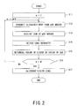
Fig. 2 is a flow chart for describing an operation of a liquid level measuring apparatus according to each embodiment. -
Fig. 3 is a block diagram illustrating a second embodiment of the liquid level measuring apparatus according to the present invention. -
Fig. 4 is a block diagram illustrating a third embodiment of the liquid level measuring apparatus according to the present invention. -
Fig. 5(A) is a graph showing a signal waveform of a single pulse transmitted/received by an ultrasonic sensor, andFig. 5(B) is a graph showing a signal waveform of a pulse train transmitter/ received by the ultrasonic sensor. -
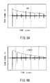
Fig. 6(A) is a graph showing a waveform of an ultrasonic wave (echo signal) reflected on an interface in contact with a gas, andFig. 6(B) is a graph showing a waveform of an ultrasonic wave (echo signal) reflected on an interface in contact with a liquid. - Hereinafter, an embodiment of the present invention is described with reference to the attached drawings.
- As illustrated in
Fig. 1 , a liquidlevel measuring apparatus 10 of a first embodiment includes: ultrasonic sensors 15 (15m; 1 ≤ m ≤ M) each configured to transmit and receive an ultrasonic wave, theultrasonic sensors 15 being respectively set at a plurality of positions on an outer surface of acontainer 21 that stores a liquid 22; a transmission/reception controlling unit 11 configured to set, as a target, any one of theultrasonic sensors 15 at the plurality of positions and control the transmission and reception of the ultrasonic wave of the target; anintensity detecting unit 12 configured to detect an intensity of the ultrasonic wave that satisfies at least 2 ≤ N (N: natural number), of the ultrasonic waves that are reflected N times on an inner surface of thecontainer 21; a gas/liquid determining unit 13 configured to determine which of the liquid 22 and a gas 24 a reflection point on the inner surface is in contact with, on a basis of the detected intensity of the ultrasonic wave; and alevel determining unit 14 configured to determine a liquid level 23 of the liquid on a basis of gas/liquid determination results respectively derived by the ultrasonic sensors 15m (1 ≤ m ≤ M) at the plurality of positions. - A reactor pressure vessel that stores reactor water (liquid 22) is illustrated as the
container 21, but thecontainer 21 to which the liquidlevel measuring apparatus 10 of the embodiment is applied is not limited to such a reactor pressure vessel. Thecontainer 21 is applied to other containers such as a container the inside of which is hot and humid, a container filled with steam, a container in which voids are generated in the liquid 22, and a container placed in a harsh environment such as a hot and high-radiation area. Examples of such containers include a light-water reactor, a fast reactor, a spent fuel pool, boilers of a steam generator and the like, and various plants at the time of an accident. - The ultrasonic sensors 15 (15m; 1 ≤ m ≤ M) are each formed by, specifically, a heat-resistant oscillator made of lithium niobate, lithium tantalate, gallium phosphate, bismuth calcium titanate, langasite, or the like.
- If such a heat-resistant oscillator is applied, even in a case where a severe accident such as a core meltdown occurs, a liquid level of the reactor pressure vessel can be reliably measured.
- The
ultrasonic sensors 15 are fixed to the outer surface of thecontainer 21 with an intermediation of a contact medium such as soft metal and gel, whereby transmission efficiency of the ultrasonic waves can be improved. - A number M of the ultrasonic sensors 15m (1 ≤ m ≤ M) is not limited. If one
ultrasonic sensor 15 is moved, theultrasonic sensor 15 can be set at the plurality of positions on the outer surface of thecontainer 21. - An electromagnetic ultrasonic probe formed by a magnet and a coil can be applied to each ultrasonic sensor. The electromagnetic ultrasonic probe enables contactless transmission/reception of the ultrasonic wave, and facilitates a change of a position of attachment to the
container 21. - Longitudinal and transverse ultrasonic waves can be transmitted/ received by adjusting placements of the magnet and the coil. In a case where the
container 21 is made of a magnetizable material, the electromagnetic ultrasonic probe (ultrasonic sensor 15) can be fixed by adsorption force of its constituent magnet. Further, a contact medium such as a couplant and water does not need to be used, and preprocessing is unnecessary. Hence, theultrasonic sensor 15 does not damage the outer surface of thecontainer 21, and can be attached to even a painted surface and an oxidized and corroded surface. - The transmission/
reception controlling unit 11 includes a transmission circuit configured to transmit a high-voltage pulse to eachultrasonic sensor 15 in a given repetition period and a reception circuit configured to receive an echo signal sent from the transmission-destinationultrasonic sensor 15. - The transmission circuit transmits a high-voltage pulse having a waveform such as an impulse waveform, a square waveform, a triangular waveform, and a sawtooth waveform such that an ultrasonic wave is generated in a frequency range (several tens of kHz to several tens of MHz) in which propagation attenuation in a steel material is relatively small.
- The transmission/
reception controlling unit 11 transmits and receives the ultrasonic wave to and from any one of theultrasonic sensors 15m at the plurality of positions, and performs gas/liquid determination thereon. After that, the transmission/reception controlling unit 11 similarly transmits and receives the ultrasonic wave to and from anotherultrasonic sensor 15m+1. - The
intensity detecting unit 12 includes an electronic circuit that performs frequency filtering and voltage amplification on a signal waveform (seeFigs. 6 ) to thereby obtain a signal intensity thereof. The signal waveform is outputted by eachultrasonic sensor 15 after receiving an ultrasonic echo from the inner surface of the container. - The ultrasonic wave that is transmitted from the
ultrasonic sensor 15 set on the outer surface of thecontainer 21 toward the inner surface of thecontainer 21 is divided into a component transmitted through the inner surface and a component reflected on the inner surface. Then, the reflected component is divided into a component that is transmitted through the outer surface to be detected by theultrasonic sensor 15 and a component that is reflected again to head for the inner surface. - Such reflection continues until the ultrasonic wave disappears due to attenuation and scattering, and an ultrasonic echo having various numbers of times N of reflection on the inner surface of the container is received by the
ultrasonic sensor 15. - Here, peak waveforms of an echo signal shown in each of
Figs. 6 respectively correspond to one-time reflection, two-time reflections, ..., N-time reflections on the inner surface of thecontainer 21 in order from a left side. - A signal intensity of the ultrasonic echo received by each
ultrasonic sensor 15 is large when the reflection point on the inner surface of thecontainer 21 is in thegas 24, and is small when the reflection point is in the liquid 22. Moreover, as the number of repetitions of reflection in a wall of thecontainer 21 increases, a difference in signal intensity between the inside of the gas and the inside of the liquid becomes more noticeable. - The reason for this is described. A reflectance R on each of the inner surface and the outer surface is represented by the following Expression (1). Here, a
medium 1 is a steel material that forms thecontainer 21, and amedium 2 is a coolant (liquid 22) or thegas 24 stored in thecontainer 21. In a case where themedium 2 is thegas 24, a reflectance Ra is equal to 1. In a case where themedium 2 is the coolant (liquid 22), roughly, a reflectance Rw is equal to 0.94 to 0.97 although the reflectance has temperature dependence. Meanwhile, in a case where the coolant (liquid 22) contains voids, the reflectance Rw may be equal to or more than 0.97 in some cases.
(Z1: an acoustic impedance of themedium 1, Z2: an acoustic impedance of the medium 2) - Each time the number of times N of reflection increases, a difference in signal intensity between: a case where the
medium 2 at the reflection point of the ultrasonic wave is the liquid 22; and a case where themedium 2 thereat is thegas 24 more noticeably appears, that is, becomes (Ra / Rw)N times. - For this reason, the
intensity detecting unit 12 in the first embodiment detects the signal intensity of the ultrasonic wave that satisfies 2 ≤ N. A specific value for N is experimentally selected such that the difference in signal intensity between the inside of the gas and the inside of the liquid more noticeably appears and that an S/N ratio can be sufficiently secured. - Such a signal intensity of the ultrasonic wave can be obtained by searching for a local maximum value of echo signals acquired in chronological order.
- Meanwhile, if a wall thickness of the
container 21 and a sound speed are known, a time when a signal intensity corresponding to each of the N-time reflections is detected can be calculated from a propagation speed of the ultrasonic wave. An intensity of an echo signal acquired at the time obtained through such calculation can be defined as the signal intensity corresponding to each of the ultrasonic echoes in the N-time reflections. - The gas/
liquid determining unit 13 determines which of the liquid 22 and thegas 24 the reflection point on the inner surface of thecontainer 21 is in contact with, on a basis of the detected intensity of the ultrasonic echo. - Specifically, because propagation attenuation of the ultrasonic wave in the wall of the
container 21 and acoustic impedances of the steel material, the coolant, and the gas are known, the signal intensities of the echo waves in the N-time reflections can be analytically obtained according to Expression (1), for both cases where the reflection point is in the gas and where the reflection point is in the liquid. - The gas/
liquid determining unit 13 recognizes which of an analytical value in the liquid and an analytical value in the gas the detection value of each signal intensity obtained by theintensity detecting unit 12 matches with, to thereby determine which of thegas 24 and the liquid 22 a position of the correspondingultrasonic sensor 15 is adjacent to. - Even in a case where the liquid 22 stored in the
container 21 is boiled to contain voids or thegas 24 contains steam and where stability of the signal intensities of the echo waves is low due to an influence of such voids or steam, a difference in signal intensity among the echo waves in the N-time reflections ≤ N) is noticeable. Hence, it is easily recognized which of the analytical value in the gas and the analytical value in the liquid the detection value of each of the signal intensities of the echo waves in the N-time reflections (2 ≤ N) matches with. - In addition to the above-mentioned method of comparing the detection value of each signal intensity with the analytical values, the gas/liquid determination of the position of the
ultrasonic sensor 15 of interest can be performed by relative comparison with the signal intensities of theultrasonic sensors 15 at the other positions. In this case, a position at which the signal intensity is relatively large can be recognized as the inside of the gas, and a position at which the signal intensity is relatively small can be recognized as the inside of the liquid. - According to another gas/liquid determining method, the signal intensity of the first ultrasonic echo in the N-time reflections at the time of attachment of each
ultrasonic sensor 15 is stored in advance. Then, the signal intensities in the N-time reflections are continuously detected in chronological order, and a change in position of the liquid level 23 is recognized by utilizing a phenomenon in which: the detection value upon a change from the inside of the gas to the inside of the liquid noticeably changes, that is, becomes (Rw / Ra)N times; and the detection value upon a change from the inside of the liquid to the inside of the gas noticeably changes, that is, becomes (Ra / Rw)N times. - The
level determining unit 14 determines the liquid level 23 of the liquid on the basis of the gas/liquid determination results respectively derived by the ultrasonic sensors 15m (1 ≤ m ≤ M) at the plurality of positions. Validity of the liquid level determination is checked on a basis of the following protocol. - (1) Each of determination results of in-gas determination and in-liquid determination is continuous, and the in-liquid determination and the in-gas determination do not alternately appear.
- (2) The in-liquid determination does not appear above the in-gas determination.
- An operation of the liquid level measuring apparatus according to each embodiment is described with reference to
Fig. 2 (seeFig. 1 as appropriate). - First, any one of the ultrasonic sensors 15m (1 ≤ m ≤ M) at the plurality of positions is set as a target (m = 1) (S11). Then, an ultrasonic wave is transmitted from the
ultrasonic sensor 151 to the container 21 (S12). Consequently, the ultrasonic wave is reflected N times (N: natural number) on the inner surface of thecontainer 21, and is received by the same ultrasonic sensor 151 (S13). - Then, a signal intensity of an echo wave corresponding to the ultrasonic wave that satisfies 2 ≤ N, of the ultrasonic waves received as described above, is detected (S14). It is determined which of the liquid and the gas a placement position of the
ultrasonic sensor 151 is adjacent to, on a basis of the detection value (S15). - The gas/liquid determination is performed on a basis of a phenomenon in which: an ultrasonic wave when the liquid level 23 is below the
ultrasonic sensor 15 at the position of interest is reflected on an interface in contact with the gas, and thus has a high reflectance; and an ultrasonic wave when the liquid level 23 is thereabove is reflected on an interface in contact with the liquid, and thus has a low reflectance. - In a case where the liquid in the container is boiling, the signal intensity of the echo wave varies, and a difference in reflectance between the inside of the gas and the inside of the liquid is slight due to an influence of steam in the gas and voids in the liquid, so that a degree of difficulty in the gas/liquid determination becomes higher. Fortunately, according to each embodiment, the signal intensity of the echo wave whose number of times N of reflection is equal to or more than two is examined, and hence accuracy of the gas/liquid determination can be kept high.
- Subsequently, another
ultrasonic sensor 152 is set as a target, and an ultrasonic wave is transmitted from the target (S16; No, S12). The gas/liquid determination is repeated in a manner similar to the above (S 13 to S 15). Then, if the gas/liquid determination on the lastultrasonic sensor 15N is ended (S16; Yes), the liquid level 23 is determined on the basis of the gas/liquid determination results respectively derived from all the ultrasonic sensors 15m (1 ≤ m ≤ M) (S17). - As illustrated in
Fig. 3 , a liquidlevel measuring apparatus 10 of a second embodiment includes an attenuationcoefficient deriving unit 18 configured to derive an attenuation coefficient of an ultrasonic wave on a basis of an intensity that is attenuated after N-time reflections, in addition to the configuration (Fig. 1 ) of the first embodiment. - The gas/
liquid determining unit 13 determines which of the liquid and the gas the reflection point on the inner surface is in contact with, on a basis of the attenuation coefficient. - In
Fig. 3 , portions that are the same as or correspond to those inFig. 1 are denoted by the same reference signs, and redundant description thereof is omitted. - The attenuation
coefficient deriving unit 18 includes an electronic circuit, and performs frequency filtering and voltage amplification on an echo waveform outputted by eachultrasonic sensor 15. - As indicated by broken lines in
Figs. 6 , the attenuationcoefficient deriving unit 18 obtains an attenuation coefficient of an attenuation curve that connect peak points respectively corresponding to n-time reflections (1 ≤ n ≤ N). - In a case where the reflection point is in the liquid (
Fig. 6(B) ), the attenuation coefficient becomes larger than in a case where the reflection point is in the gas (Fig. 6(A) ). In this way, the attenuation coefficient of the attenuation curve obtained from the echo signals that are received from the first time to the Nth time by eachultrasonic sensor 15 enables determination as to whether the reflection point in the container is in the gas or in the liquid. - According to the second embodiment, because the plurality of echo waves in the n-time reflections (1 1 ≤ n ≤ N) are considered, an influence of fluctuations in a single echo wave is reduced, and hence accuracy of the gas/liquid determination can be kept high.
- As illustrated in
Fig. 4 , a liquidlevel measuring apparatus 10 of a third embodiment includes a pulsetrain generating unit 16 configured to generate an ultrasonic wave made of a plurality of pulse trains, in addition to the configuration (Fig. 1 ) of the first embodiment. - The transmission/
reception controlling unit 11 causes eachultrasonic sensor 15 to transmit the ultrasonic wave made of the pulse trains. - In
Fig. 4 , portions that are the same as or correspond to those inFig. 1 are denoted by the same reference signs, and redundant description thereof is omitted. - A transmitted/ received ultrasonic wave generally has a waveform similar to a single pulse waveform as shown in
Fig. 5(A) , whereas a transmitted/received ultrasonic wave in the third embodiment has such a pulse train (number of continuous waves: p = 10) as shown inFig. 5(B) . - The pulse
train generating unit 16 can freely set the number of continuous waves p, and can set an arbitrary waveform such as a spike pulse waveform and a square waveform. - Here, in a case where the liquid in the container is boiling, stability of the signal intensity of the echo wave becomes lower due to an influence of steam in the gas and voids in the liquid, and hence a decrease in accuracy of the gas/liquid determination is a concern. In view of this, the gas/liquid determination is performed by using the ultrasonic pulse train shown in
Fig. 5(B) and calculating an average value of respective intensities of pulses having the number of continuous waves p. - As a result, because an influence of fluctuations in the pulses is reduced by such averaging, even in a case where the liquid in the container is boiling, accuracy of the gas/liquid determination can be kept high.
- The liquid
level measuring apparatus 10 of the third embodiment further includes afrequency setting unit 17 configured to set a frequency of the ultrasonic wave to a resonance point of thecontainer 21. - The transmission/
reception controlling unit 11 causes eachultrasonic sensor 15 to transmit the ultrasonic wave whose frequency is set to the resonance point. - The
frequency setting unit 17 can set the frequency of the ultrasonic wave within a range of ten kHz to several tens of MHz. Here, a resonance frequency refers to a frequency at which a length of an integral multiple of half a wavelength of the ultrasonic wave coincides with a thickness of the container. Because a thickness of the reactor pressure vessel is approximately 100 to 300 mm, a lower limit of the set frequency is 10 kHz in a case of using a longitudinal wave. On the other hand, an upper limit of the set frequency is approximately several tens of MHz, which is such a value that does not increase an influence of propagation attenuation in the steel material. The frequency can be changed by changing duration of a pulse voltage. - The signal intensity of the ultrasonic wave received by each
ultrasonic sensor 15 is noticeably attenuated by reflection due to a resonance effect. Accordingly, even if the medium in contact with the inner surface of the container is the gas or the liquid and if the difference in reflectance therebetween is slight, the use of the ultrasonic wave having the resonance frequency enables the difference in signal intensity therebetween to noticeably appear. - Further, the number of continuous waves p can be set to ∞, and a continuous ultrasonic sine wave can be transmitted from each
ultrasonic sensor 15 to thecontainer 21. The ultrasonic wave is repetitively reflected between the inner surface and the outer surface of the container, and an ultrasonic wave that is transmitted through the outer surface at the time of reflection thereon is received by theultrasonic sensor 15. - In a liquid
level measuring apparatus 10 according to another embodiment, the transmission/reception controlling unit 11 causes eachultrasonic sensor 15 to transmit an ultrasonic wave having a wideband frequency including the resonance point. - The transmission/
reception controlling unit 11 in this case can utilize the resonance frequency without frequency adjustment, and hence thefrequency setting unit 17 is unnecessary. In this case, it is desirable to use, as theultrasonic sensor 15, a composite probe that can transmit/receive an ultrasonic wave having a wide frequency bandwidth. - This enables transmission/reception of a wideband ultrasonic wave including the resonance frequency corresponding to the thickness of the
container 21, and can increase detection sensitivity of the ultrasonic wave without frequency adjustment work. Note that the number of resonance points is not one but more than one, and a wideband frequency including the plurality of resonance points can be selected. - The liquid level measuring apparatus of at least one embodiment described above performs the gas/liquid determination on a basis of an ultrasonic wave that is attenuated after being reflected twice or more, of ultrasonic waves that are multiply reflected between the inner surface and the outer surface of the container. This enables highly accurate measurement of the liquid level formed by the liquid containing voids and the gas containing steam.
- Although some embodiments of the present invention have been described, these embodiments are presented as mere examples, and are not intended to limit the scope of the present invention. These embodiments can be carried out in various other modes, and can be variously omitted, replaced, changed, and combined within a range not departing from the gist of the present invention. These embodiments and modifications thereof are included in the scope and gist of the present invention, and are also included in the invention described in CLAIMS and a range equivalent thereto.
- Components of the liquid level measuring apparatus can be implemented by a processor of a computer, and a plurality of processors can be operated by a liquid level measuring program.
- 10...liquid level measuring apparatus, 11...transmission/reception controlling unit, 12...intensity detecting unit, 13...gas/liquid determining unit, 14...level determining unit, 15(151,152,15m,15M)...ultrasonic sensor, 16...pulse train generating unit, 17...frequency setting unit, 18...attenuation coefficient deriving unit, 21...container, 22... liquid, 23...liquid level, 24...gas
Claims (8)
- A liquid level measuring apparatus comprising:ultrasonic sensors each configured to transmit and receive an ultrasonic wave, the ultrasonic sensors being respectively set at a plurality of positions on an outer surface of a container that stores a liquid;a transmission/reception controlling unit configured to set, as a target, any one of the ultrasonic sensors at the plurality of positions and control the transmission and reception of the ultrasonic wave of the target;an intensity detecting unit configured to detect an intensity of the ultrasonic wave that satisfies at least 2 ≤ N (N: natural number), of the ultrasonic waves that are reflected N times on an inner surface of the container;a gas/liquid determining unit configured to determine which of the liquid and a gas a reflection point on the inner surface is in contact with, on a basis of the detected intensity of the ultrasonic wave; anda level determining unit configured to determine a liquid level of the liquid on a basis of gas/liquid determination results respectively derived by the ultrasonic sensors at the plurality of positions.
- The liquid level measuring apparatus according to claim 1, further comprising an attenuation coefficient deriving unit configured to derive an attenuation coefficient of the ultrasonic wave on a basis of an intensity that is attenuated after the N-time reflections, wherein
the gas/liquid determining unit determines which of the liquid and the gas the reflection point on the inner surface is in contact with, on a basis of the attenuation coefficient. - The liquid level measuring apparatus according to claim 1, further comprising a pulse train generating unit configured to generate an ultrasonic wave made of a plurality of pulse trains, wherein
the transmission/reception controlling unit causes each of the ultrasonic sensors to transmit the ultrasonic wave made of the pulse trains. - The liquid level measuring apparatus according to claim 1, further comprising a frequency setting unit configured to set a frequency of the ultrasonic wave to a resonance point of the container, wherein
the transmission/reception controlling unit causes each of the ultrasonic sensors to transmit the ultrasonic wave whose frequency is set to the resonance point. - The liquid level measuring apparatus according to claim 1, wherein
the transmission/reception controlling unit causes each of the ultrasonic sensors to transmit an ultrasonic wave having a wideband frequency including a resonance point of the container. - The liquid level measuring apparatus according to claim 1, wherein
each of the ultrasonic sensors is an electromagnetic ultrasonic probe formed by a magnet and a coil. - A liquid level measuring method comprising the steps of:setting, as a target, any one of ultrasonic sensors each configured to transmit and receive an ultrasonic wave, and controlling the transmission and reception of the ultrasonic wave of the target, the ultrasonic sensors being respectively set at a plurality of positions on an outer surface of a container that stores a liquid;detecting an intensity of the ultrasonic wave that satisfies at least 2 ≤ N (N: natural number), of the ultrasonic waves that are reflected N times on an inner surface of the container;determining which of the liquid and a gas a reflection point on the inner surface is in contact with, on a basis of the detected intensity of the ultrasonic wave; anddetermining a liquid level of the liquid on a basis of gas/liquid determination results respectively derived by the ultrasonic sensors at the plurality of positions.
- A liquid level measuring program causing a computer to execute the steps of:setting, as a target, any one of ultrasonic sensors each configured to transmit and receive an ultrasonic wave, and controlling the transmission and reception of the ultrasonic wave of the target, the ultrasonic sensors being respectively set at a plurality of positions on an outer surface of a container that stores a liquid;detecting an intensity of the ultrasonic wave that satisfies at least 2 ≤ N (N: natural number), of the ultrasonic waves that are reflected N times on an inner surface of the container;determining which of the liquid and a gas a reflection point on the inner surface is in contact with, on a basis of the detected intensity of the ultrasonic wave; anddetermining a liquid level of the liquid on a basis of gas/liquid determination results respectively derived by the ultrasonic sensors at the plurality of positions.
Applications Claiming Priority (2)
| Application Number | Priority Date | Filing Date | Title |
|---|---|---|---|
| JP2011289625A JP5774469B2 (en) | 2011-12-28 | 2011-12-28 | Liquid level measuring device, method and program |
| PCT/JP2012/083855 WO2013100046A1 (en) | 2011-12-28 | 2012-12-27 | Liquid surface level measurement device, method, and program |
Publications (3)
| Publication Number | Publication Date |
|---|---|
| EP2799820A1 true EP2799820A1 (en) | 2014-11-05 |
| EP2799820A4 EP2799820A4 (en) | 2015-09-16 |
| EP2799820B1 EP2799820B1 (en) | 2019-06-12 |
Family
ID=48697525
Family Applications (1)
| Application Number | Title | Priority Date | Filing Date |
|---|---|---|---|
| EP12861404.7A Not-in-force EP2799820B1 (en) | 2011-12-28 | 2012-12-27 | Liquid surface level measurement device, method, and program |
Country Status (4)
| Country | Link |
|---|---|
| US (1) | US9557208B2 (en) |
| EP (1) | EP2799820B1 (en) |
| JP (1) | JP5774469B2 (en) |
| WO (1) | WO2013100046A1 (en) |
Families Citing this family (32)
| Publication number | Priority date | Publication date | Assignee | Title |
|---|---|---|---|---|
| JP2015052525A (en) * | 2013-09-06 | 2015-03-19 | 株式会社東芝 | Liquid level measuring device and measuring method thereof |
| CN103528771B (en) * | 2013-10-11 | 2015-11-18 | 广州供电局有限公司 | A kind of method measuring oil leakage fault of cable terminal porcelain sleeve |
| US10168305B2 (en) * | 2013-10-17 | 2019-01-01 | Battelle Memorial Institute | Container screening system and method |
| US10724968B2 (en) | 2014-03-21 | 2020-07-28 | Battelle Memorial Institute | System and method for solution constituent and concentration identification |
| DE102014113470A1 (en) * | 2014-09-18 | 2016-03-24 | Maschinenfabrik Reinhausen Gmbh | Electric device with a housing filled with insulating oil and measuring device and method for monitoring such an electrical device |
| US20160320226A1 (en) * | 2015-04-30 | 2016-11-03 | Siemens Industry, Inc. | Determining height of a liquid level interface in a container from acoustic signal or echo time measurement |
| JP6637738B2 (en) * | 2015-11-17 | 2020-01-29 | 日立Geニュークリア・エナジー株式会社 | Reactor water level estimation device |
| JP7151344B2 (en) * | 2018-10-01 | 2022-10-12 | 富士電機株式会社 | Pressure measuring device |
| DE102018218066A1 (en) * | 2018-10-22 | 2020-04-23 | Continental Automotive Gmbh | Method and device for determining the level and / or the quality of a fluid in a fluid container |
| JP7206539B2 (en) * | 2018-12-18 | 2023-01-18 | 株式会社竹中工務店 | Concrete filling management method |
| US10746716B1 (en) | 2019-05-31 | 2020-08-18 | Battelle Memorial Institute | System and method for solution constituent and concentration identification |
| US11231311B2 (en) | 2019-05-31 | 2022-01-25 | Perceptive Sensor Technologies Llc | Non-linear ultrasound method and apparatus for quantitative detection of materials |
| KR102353351B1 (en) * | 2020-09-29 | 2022-01-18 | 한국수력원자력 주식회사 | Water level measurement system |
| KR102351037B1 (en) | 2020-09-29 | 2022-01-12 | 한국수력원자력 주식회사 | Water level measurement system |
| CN112325985B (en) * | 2020-10-22 | 2021-09-07 | 北京卫星环境工程研究所 | A device and method for measuring the remaining amount of propellant in an on-orbit spacecraft tank |
| WO2022120074A1 (en) | 2020-12-02 | 2022-06-09 | Perceptive Sensor Technologies Llc | Variable angle transducer interface block |
| US11549839B2 (en) | 2020-12-04 | 2023-01-10 | Perceptive Sensor Technologies, Inc. | Systems and methods for determining floating roof level tilt and characterizing runoff |
| EP4256283A4 (en) | 2020-12-04 | 2025-02-26 | Perceptive Sensor Technologies, Inc. | DEVICE, SYSTEM AND METHOD FOR DETECTING OBJECTS AND ACTIVITY IN A CONTAINER |
| US11788904B2 (en) | 2020-12-04 | 2023-10-17 | Perceptive Sensor Technologies, Inc. | Acoustic temperature measurement in layered environments |
| US11604294B2 (en) | 2020-12-04 | 2023-03-14 | Perceptive Sensor Technologies, Inc. | Determining layer characteristics in multi-layered environments |
| CN116917729A (en) * | 2020-12-04 | 2023-10-20 | 感知传感器技术股份有限公司 | Improvements in material detection using multipath acoustic signals |
| CN116940810A (en) * | 2020-12-04 | 2023-10-24 | 感知传感器技术股份有限公司 | Multiple reflection acoustic signal material detection |
| US11536696B2 (en) | 2020-12-04 | 2022-12-27 | Perceptive Sensor Technologies, Inc. | In-wall multi-bounce material property detection and acoustic signal amplification |
| EP4256296A4 (en) | 2020-12-04 | 2025-03-12 | Perceptive Sensor Technologies, Inc. | ACOUSTIC TEMPERATURE MEASUREMENT IN LAYERED ENVIRONMENTS |
| CN116888468A (en) | 2020-12-30 | 2023-10-13 | 感知传感器技术股份有限公司 | Evaluate fluid quality using signals |
| CN113029292A (en) * | 2021-03-19 | 2021-06-25 | 青海西钢自动化信息技术有限公司 | Application of ultrasonic detector in oil-gas lubrication of rolling mill |
| WO2023154514A1 (en) | 2022-02-11 | 2023-08-17 | Perceptive Sensor Technologies, Inc. | Acoustic signal detection of material composition in static and dynamic conditions |
| WO2024091308A1 (en) | 2022-07-19 | 2024-05-02 | Perceptive Sensor Technologies, Inc. | Acoustic signal material identification with nanotube couplant |
| US12625111B2 (en) * | 2022-09-14 | 2026-05-12 | Yokogawa Electric Corporation | Measurement apparatus and measurement method |
| CN116818048A (en) * | 2023-06-29 | 2023-09-29 | 北京星河动力装备科技有限公司 | Tank liquid level measuring method and device, electronic equipment and readable storage medium |
| CN117073804B (en) * | 2023-08-22 | 2024-06-21 | 陕西声科电子科技有限公司 | Plug-in ultrasonic liquid level switch |
| JP2025187193A (en) * | 2024-06-13 | 2025-12-25 | ホシデン株式会社 | Inspection System |
Family Cites Families (21)
| Publication number | Priority date | Publication date | Assignee | Title |
|---|---|---|---|---|
| US4203324A (en) * | 1977-08-05 | 1980-05-20 | Joseph Baumoel | Sonic liquid level detector |
| US4320659A (en) * | 1978-02-27 | 1982-03-23 | Panametrics, Inc. | Ultrasonic system for measuring fluid impedance or liquid level |
| JPS559103A (en) * | 1978-07-05 | 1980-01-23 | Mitsubishi Heavy Ind Ltd | Level detecter at hopper of unhardened concrete |
| JPS61274223A (en) * | 1985-05-30 | 1986-12-04 | Hitachi Constr Mach Co Ltd | Level detection of liquid reservoir by supersonic wave |
| DE3732219A1 (en) * | 1987-09-24 | 1989-04-13 | Siemens Ag | APPLICATION OF ELECTROMAGNETIC ULTRASOUND TRANSFORMATION METHODS FOR MONITORING FUEL HEAT AND BUBBLE CONDITIONING IN LIQUID CONTAINING PIPES |
| US5195058A (en) * | 1992-04-30 | 1993-03-16 | The United States Of America As Represented By The Secretary Of The Air Force | Ultrasonic method for non-intrusive low liquid level sensing |
| JP3299655B2 (en) * | 1995-03-17 | 2002-07-08 | 株式会社日立製作所 | Ultrasonic flaw detector and method for inspecting multilayer structure |
| US5880364A (en) * | 1997-10-31 | 1999-03-09 | Cosense, Inc. | Non-contact ultrasonic micromeasurement system |
| JP3732642B2 (en) * | 1998-01-30 | 2006-01-05 | 株式会社東芝 | Ultrasonic liquid level measuring device |
| US6644114B1 (en) * | 1999-12-30 | 2003-11-11 | Mcewan Technologies, Llc | Direct PWM reflectometer |
| JP2001194210A (en) | 2000-01-14 | 2001-07-19 | Tokyo Electric Power Co Inc:The | Ultrasonic level measuring apparatus |
| JP2002340654A (en) * | 2001-05-18 | 2002-11-27 | Hitachi Ltd | Liquid level detection method and apparatus by sound |
| JP2003315030A (en) * | 2002-04-22 | 2003-11-06 | Kinden Corp | Ultrasonic measurement sensor, ultrasonic measurement device, and method of measuring state of object to be measured |
| US6795015B2 (en) * | 2003-01-29 | 2004-09-21 | Saab Rosemount Tank Radar Ab | Bottom reflector for a radar-based level gauge |
| WO2004074782A2 (en) * | 2003-02-14 | 2004-09-02 | Adept Science & Technologies, Llc | Ultrasonic liquid level monitor |
| US6834546B2 (en) * | 2003-03-04 | 2004-12-28 | Saab Rosemount Tank Radar Ab | Device and method in a level gauging system |
| EP1921427B1 (en) * | 2006-11-07 | 2019-02-27 | LG Electronics Inc. | Automatic liquid dispensers with liquid level detector |
| US8167004B2 (en) * | 2007-02-14 | 2012-05-01 | Lg Electronics Inc. | Automatic liquid dispensers |
| JP2008203204A (en) * | 2007-02-22 | 2008-09-04 | Ricoh Elemex Corp | Liquid detector |
| US8069721B2 (en) * | 2007-05-16 | 2011-12-06 | Rosemount Tank Radar Ab | Radar level gauge system having limited transmission power |
| US9052230B2 (en) * | 2011-05-13 | 2015-06-09 | Chevron U.S.A. Inc | Industrial process monitoring and imaging |
-
2011
- 2011-12-28 JP JP2011289625A patent/JP5774469B2/en not_active Expired - Fee Related
-
2012
- 2012-12-27 US US14/369,513 patent/US9557208B2/en not_active Expired - Fee Related
- 2012-12-27 EP EP12861404.7A patent/EP2799820B1/en not_active Not-in-force
- 2012-12-27 WO PCT/JP2012/083855 patent/WO2013100046A1/en not_active Ceased
Also Published As
| Publication number | Publication date |
|---|---|
| JP2013140029A (en) | 2013-07-18 |
| US20140366626A1 (en) | 2014-12-18 |
| JP5774469B2 (en) | 2015-09-09 |
| WO2013100046A1 (en) | 2013-07-04 |
| US9557208B2 (en) | 2017-01-31 |
| EP2799820A4 (en) | 2015-09-16 |
| EP2799820B1 (en) | 2019-06-12 |
Similar Documents
| Publication | Publication Date | Title |
|---|---|---|
| EP2799820B1 (en) | Liquid surface level measurement device, method, and program | |
| EP2857834B1 (en) | Ultrasonic pipe measurement apparatus | |
| CN101614533A (en) | A method and instrument capable of accurately measuring the thickness of an ultra-thin workpiece | |
| JP2017096857A (en) | Ultrasonic thinning inspection method and inspection apparatus | |
| WO2004029564A1 (en) | Broadband long pulse ultrasonic inspection | |
| EP2356440B1 (en) | Method for determining the starting instant of an acoustic signal response | |
| JP5507267B2 (en) | Method and apparatus for calculating thickness of damping material | |
| JP5461979B2 (en) | Reactor vibration monitoring apparatus and monitoring method thereof | |
| JP2011133241A5 (en) | ||
| CN116429669B (en) | A corrosion detection method for sheet metal | |
| US20040100282A1 (en) | Method and apparatus for determination of layer thickness in a multi-layer structure | |
| RU108627U1 (en) | PIPELINE ULTRASONIC DEFECTOSCOPY SYSTEM | |
| US8473246B1 (en) | Cable measurement device | |
| JP5224912B2 (en) | Vibration monitoring apparatus and monitoring method | |
| JP5940350B2 (en) | Vibration measuring apparatus and vibration measuring method | |
| JPH07198362A (en) | Pipe thinning measurement method and device | |
| JP3169534B2 (en) | Inundation detection method | |
| JP2007064904A (en) | Ultrasonic thickness measuring method and apparatus | |
| US20020100326A1 (en) | Method and apparatus for measuring ultrasonic properties of an object | |
| CN202304777U (en) | Workpiece thickness measurement device | |
| JP2011180052A (en) | Reactor water-level meter and method of measuring reactor water level | |
| JP2008014868A (en) | Method for measuring attached material, and apparatus for measuring the attached material | |
| RU2540942C1 (en) | Method to monitor dynamics of variation of controlled object wall thickness | |
| RU2687086C1 (en) | Method of ultrasonic monitoring of pipeline wall thickness | |
| JP5059344B2 (en) | Plate thickness measuring apparatus and measuring method |
Legal Events
| Date | Code | Title | Description |
|---|---|---|---|
| PUAI | Public reference made under article 153(3) epc to a published international application that has entered the european phase |
Free format text: ORIGINAL CODE: 0009012 |
|
| 17P | Request for examination filed |
Effective date: 20140627 |
|
| AK | Designated contracting states |
Kind code of ref document: A1 Designated state(s): AL AT BE BG CH CY CZ DE DK EE ES FI FR GB GR HR HU IE IS IT LI LT LU LV MC MK MT NL NO PL PT RO RS SE SI SK SM TR |
|
| DAX | Request for extension of the european patent (deleted) | ||
| RA4 | Supplementary search report drawn up and despatched (corrected) |
Effective date: 20150819 |
|
| RIC1 | Information provided on ipc code assigned before grant |
Ipc: G01F 23/28 20060101AFI20150813BHEP Ipc: G01F 23/296 20060101ALI20150813BHEP Ipc: G21C 17/035 20060101ALI20150813BHEP |
|
| STAA | Information on the status of an ep patent application or granted ep patent |
Free format text: STATUS: EXAMINATION IS IN PROGRESS |
|
| 17Q | First examination report despatched |
Effective date: 20181018 |
|
| REG | Reference to a national code |
Ref country code: DE Ref legal event code: R079 Ref document number: 602012061029 Country of ref document: DE Free format text: PREVIOUS MAIN CLASS: G01F0023280000 Ipc: G01F0023296000 |
|
| GRAP | Despatch of communication of intention to grant a patent |
Free format text: ORIGINAL CODE: EPIDOSNIGR1 |
|
| STAA | Information on the status of an ep patent application or granted ep patent |
Free format text: STATUS: GRANT OF PATENT IS INTENDED |
|
| RIC1 | Information provided on ipc code assigned before grant |
Ipc: F01K 5/02 20060101ALI20190117BHEP Ipc: G01F 23/296 20060101AFI20190117BHEP Ipc: G21C 17/035 20060101ALI20190117BHEP |
|
| INTG | Intention to grant announced |
Effective date: 20190214 |
|
| GRAS | Grant fee paid |
Free format text: ORIGINAL CODE: EPIDOSNIGR3 |
|
| GRAA | (expected) grant |
Free format text: ORIGINAL CODE: 0009210 |
|
| STAA | Information on the status of an ep patent application or granted ep patent |
Free format text: STATUS: THE PATENT HAS BEEN GRANTED |
|
| AK | Designated contracting states |
Kind code of ref document: B1 Designated state(s): AL AT BE BG CH CY CZ DE DK EE ES FI FR GB GR HR HU IE IS IT LI LT LU LV MC MK MT NL NO PL PT RO RS SE SI SK SM TR |
|
| REG | Reference to a national code |
Ref country code: GB Ref legal event code: FG4D |
|
| RIN1 | Information on inventor provided before grant (corrected) |
Inventor name: SHIRAISHI, FUJIO Inventor name: KURODA, HIDEHIKO Inventor name: MUKAI, NARUHIKO Inventor name: TAKEMURA, MAKOTO Inventor name: TAKADA, YUKA Inventor name: KAWAKAMI, OSAMU |
|
| REG | Reference to a national code |
Ref country code: CH Ref legal event code: EP |
|
| REG | Reference to a national code |
Ref country code: AT Ref legal event code: REF Ref document number: 1143166 Country of ref document: AT Kind code of ref document: T Effective date: 20190615 |
|
| REG | Reference to a national code |
Ref country code: DE Ref legal event code: R096 Ref document number: 602012061029 Country of ref document: DE |
|
| REG | Reference to a national code |
Ref country code: IE Ref legal event code: FG4D |
|
| REG | Reference to a national code |
Ref country code: SE Ref legal event code: TRGR |
|
| REG | Reference to a national code |
Ref country code: NL Ref legal event code: MP Effective date: 20190612 |
|
| REG | Reference to a national code |
Ref country code: LT Ref legal event code: MG4D |
|
| PG25 | Lapsed in a contracting state [announced via postgrant information from national office to epo] |
Ref country code: LT Free format text: LAPSE BECAUSE OF FAILURE TO SUBMIT A TRANSLATION OF THE DESCRIPTION OR TO PAY THE FEE WITHIN THE PRESCRIBED TIME-LIMIT Effective date: 20190612 Ref country code: FI Free format text: LAPSE BECAUSE OF FAILURE TO SUBMIT A TRANSLATION OF THE DESCRIPTION OR TO PAY THE FEE WITHIN THE PRESCRIBED TIME-LIMIT Effective date: 20190612 Ref country code: HR Free format text: LAPSE BECAUSE OF FAILURE TO SUBMIT A TRANSLATION OF THE DESCRIPTION OR TO PAY THE FEE WITHIN THE PRESCRIBED TIME-LIMIT Effective date: 20190612 Ref country code: NO Free format text: LAPSE BECAUSE OF FAILURE TO SUBMIT A TRANSLATION OF THE DESCRIPTION OR TO PAY THE FEE WITHIN THE PRESCRIBED TIME-LIMIT Effective date: 20190912 Ref country code: AL Free format text: LAPSE BECAUSE OF FAILURE TO SUBMIT A TRANSLATION OF THE DESCRIPTION OR TO PAY THE FEE WITHIN THE PRESCRIBED TIME-LIMIT Effective date: 20190612 |
|
| PG25 | Lapsed in a contracting state [announced via postgrant information from national office to epo] |
Ref country code: RS Free format text: LAPSE BECAUSE OF FAILURE TO SUBMIT A TRANSLATION OF THE DESCRIPTION OR TO PAY THE FEE WITHIN THE PRESCRIBED TIME-LIMIT Effective date: 20190612 Ref country code: LV Free format text: LAPSE BECAUSE OF FAILURE TO SUBMIT A TRANSLATION OF THE DESCRIPTION OR TO PAY THE FEE WITHIN THE PRESCRIBED TIME-LIMIT Effective date: 20190612 Ref country code: GR Free format text: LAPSE BECAUSE OF FAILURE TO SUBMIT A TRANSLATION OF THE DESCRIPTION OR TO PAY THE FEE WITHIN THE PRESCRIBED TIME-LIMIT Effective date: 20190913 Ref country code: BG Free format text: LAPSE BECAUSE OF FAILURE TO SUBMIT A TRANSLATION OF THE DESCRIPTION OR TO PAY THE FEE WITHIN THE PRESCRIBED TIME-LIMIT Effective date: 20190912 |
|
| REG | Reference to a national code |
Ref country code: AT Ref legal event code: MK05 Ref document number: 1143166 Country of ref document: AT Kind code of ref document: T Effective date: 20190612 |
|
| PG25 | Lapsed in a contracting state [announced via postgrant information from national office to epo] |
Ref country code: NL Free format text: LAPSE BECAUSE OF FAILURE TO SUBMIT A TRANSLATION OF THE DESCRIPTION OR TO PAY THE FEE WITHIN THE PRESCRIBED TIME-LIMIT Effective date: 20190612 Ref country code: AT Free format text: LAPSE BECAUSE OF FAILURE TO SUBMIT A TRANSLATION OF THE DESCRIPTION OR TO PAY THE FEE WITHIN THE PRESCRIBED TIME-LIMIT Effective date: 20190612 Ref country code: PT Free format text: LAPSE BECAUSE OF FAILURE TO SUBMIT A TRANSLATION OF THE DESCRIPTION OR TO PAY THE FEE WITHIN THE PRESCRIBED TIME-LIMIT Effective date: 20191014 Ref country code: RO Free format text: LAPSE BECAUSE OF FAILURE TO SUBMIT A TRANSLATION OF THE DESCRIPTION OR TO PAY THE FEE WITHIN THE PRESCRIBED TIME-LIMIT Effective date: 20190612 Ref country code: CZ Free format text: LAPSE BECAUSE OF FAILURE TO SUBMIT A TRANSLATION OF THE DESCRIPTION OR TO PAY THE FEE WITHIN THE PRESCRIBED TIME-LIMIT Effective date: 20190612 Ref country code: SK Free format text: LAPSE BECAUSE OF FAILURE TO SUBMIT A TRANSLATION OF THE DESCRIPTION OR TO PAY THE FEE WITHIN THE PRESCRIBED TIME-LIMIT Effective date: 20190612 Ref country code: EE Free format text: LAPSE BECAUSE OF FAILURE TO SUBMIT A TRANSLATION OF THE DESCRIPTION OR TO PAY THE FEE WITHIN THE PRESCRIBED TIME-LIMIT Effective date: 20190612 |
|
| PG25 | Lapsed in a contracting state [announced via postgrant information from national office to epo] |
Ref country code: ES Free format text: LAPSE BECAUSE OF FAILURE TO SUBMIT A TRANSLATION OF THE DESCRIPTION OR TO PAY THE FEE WITHIN THE PRESCRIBED TIME-LIMIT Effective date: 20190612 Ref country code: IS Free format text: LAPSE BECAUSE OF FAILURE TO SUBMIT A TRANSLATION OF THE DESCRIPTION OR TO PAY THE FEE WITHIN THE PRESCRIBED TIME-LIMIT Effective date: 20191012 Ref country code: SM Free format text: LAPSE BECAUSE OF FAILURE TO SUBMIT A TRANSLATION OF THE DESCRIPTION OR TO PAY THE FEE WITHIN THE PRESCRIBED TIME-LIMIT Effective date: 20190612 Ref country code: IT Free format text: LAPSE BECAUSE OF FAILURE TO SUBMIT A TRANSLATION OF THE DESCRIPTION OR TO PAY THE FEE WITHIN THE PRESCRIBED TIME-LIMIT Effective date: 20190612 |
|
| PGFP | Annual fee paid to national office [announced via postgrant information from national office to epo] |
Ref country code: FR Payment date: 20191115 Year of fee payment: 8 |
|
| REG | Reference to a national code |
Ref country code: DE Ref legal event code: R097 Ref document number: 602012061029 Country of ref document: DE |
|
| PG25 | Lapsed in a contracting state [announced via postgrant information from national office to epo] |
Ref country code: TR Free format text: LAPSE BECAUSE OF FAILURE TO SUBMIT A TRANSLATION OF THE DESCRIPTION OR TO PAY THE FEE WITHIN THE PRESCRIBED TIME-LIMIT Effective date: 20190612 |
|
| PLBE | No opposition filed within time limit |
Free format text: ORIGINAL CODE: 0009261 |
|
| STAA | Information on the status of an ep patent application or granted ep patent |
Free format text: STATUS: NO OPPOSITION FILED WITHIN TIME LIMIT |
|
| PG25 | Lapsed in a contracting state [announced via postgrant information from national office to epo] |
Ref country code: DK Free format text: LAPSE BECAUSE OF FAILURE TO SUBMIT A TRANSLATION OF THE DESCRIPTION OR TO PAY THE FEE WITHIN THE PRESCRIBED TIME-LIMIT Effective date: 20190612 Ref country code: PL Free format text: LAPSE BECAUSE OF FAILURE TO SUBMIT A TRANSLATION OF THE DESCRIPTION OR TO PAY THE FEE WITHIN THE PRESCRIBED TIME-LIMIT Effective date: 20190612 |
|
| 26N | No opposition filed |
Effective date: 20200313 |
|
| PG25 | Lapsed in a contracting state [announced via postgrant information from national office to epo] |
Ref country code: SI Free format text: LAPSE BECAUSE OF FAILURE TO SUBMIT A TRANSLATION OF THE DESCRIPTION OR TO PAY THE FEE WITHIN THE PRESCRIBED TIME-LIMIT Effective date: 20190612 Ref country code: IS Free format text: LAPSE BECAUSE OF FAILURE TO SUBMIT A TRANSLATION OF THE DESCRIPTION OR TO PAY THE FEE WITHIN THE PRESCRIBED TIME-LIMIT Effective date: 20200224 |
|
| REG | Reference to a national code |
Ref country code: DE Ref legal event code: R119 Ref document number: 602012061029 Country of ref document: DE |
|
| PG2D | Information on lapse in contracting state deleted |
Ref country code: IS |
|
| REG | Reference to a national code |
Ref country code: CH Ref legal event code: PL |
|
| REG | Reference to a national code |
Ref country code: BE Ref legal event code: MM Effective date: 20191231 |
|
| PG25 | Lapsed in a contracting state [announced via postgrant information from national office to epo] |
Ref country code: MC Free format text: LAPSE BECAUSE OF FAILURE TO SUBMIT A TRANSLATION OF THE DESCRIPTION OR TO PAY THE FEE WITHIN THE PRESCRIBED TIME-LIMIT Effective date: 20190612 |
|
| GBPC | Gb: european patent ceased through non-payment of renewal fee |
Effective date: 20191227 |
|
| PG25 | Lapsed in a contracting state [announced via postgrant information from national office to epo] |
Ref country code: LU Free format text: LAPSE BECAUSE OF NON-PAYMENT OF DUE FEES Effective date: 20191227 Ref country code: GB Free format text: LAPSE BECAUSE OF NON-PAYMENT OF DUE FEES Effective date: 20191227 Ref country code: DE Free format text: LAPSE BECAUSE OF NON-PAYMENT OF DUE FEES Effective date: 20200701 Ref country code: IE Free format text: LAPSE BECAUSE OF NON-PAYMENT OF DUE FEES Effective date: 20191227 |
|
| PG25 | Lapsed in a contracting state [announced via postgrant information from national office to epo] |
Ref country code: BE Free format text: LAPSE BECAUSE OF NON-PAYMENT OF DUE FEES Effective date: 20191231 Ref country code: LI Free format text: LAPSE BECAUSE OF NON-PAYMENT OF DUE FEES Effective date: 20191231 Ref country code: CH Free format text: LAPSE BECAUSE OF NON-PAYMENT OF DUE FEES Effective date: 20191231 |
|
| PG25 | Lapsed in a contracting state [announced via postgrant information from national office to epo] |
Ref country code: CY Free format text: LAPSE BECAUSE OF FAILURE TO SUBMIT A TRANSLATION OF THE DESCRIPTION OR TO PAY THE FEE WITHIN THE PRESCRIBED TIME-LIMIT Effective date: 20190612 |
|
| PG25 | Lapsed in a contracting state [announced via postgrant information from national office to epo] |
Ref country code: MT Free format text: LAPSE BECAUSE OF FAILURE TO SUBMIT A TRANSLATION OF THE DESCRIPTION OR TO PAY THE FEE WITHIN THE PRESCRIBED TIME-LIMIT Effective date: 20190612 Ref country code: HU Free format text: LAPSE BECAUSE OF FAILURE TO SUBMIT A TRANSLATION OF THE DESCRIPTION OR TO PAY THE FEE WITHIN THE PRESCRIBED TIME-LIMIT; INVALID AB INITIO Effective date: 20121227 |
|
| PG25 | Lapsed in a contracting state [announced via postgrant information from national office to epo] |
Ref country code: FR Free format text: LAPSE BECAUSE OF NON-PAYMENT OF DUE FEES Effective date: 20201231 |
|
| PGFP | Annual fee paid to national office [announced via postgrant information from national office to epo] |
Ref country code: SE Payment date: 20211110 Year of fee payment: 10 |
|
| PG25 | Lapsed in a contracting state [announced via postgrant information from national office to epo] |
Ref country code: MK Free format text: LAPSE BECAUSE OF FAILURE TO SUBMIT A TRANSLATION OF THE DESCRIPTION OR TO PAY THE FEE WITHIN THE PRESCRIBED TIME-LIMIT Effective date: 20190612 |
|
| REG | Reference to a national code |
Ref country code: SE Ref legal event code: EUG |
|
| PG25 | Lapsed in a contracting state [announced via postgrant information from national office to epo] |
Ref country code: SE Free format text: LAPSE BECAUSE OF NON-PAYMENT OF DUE FEES Effective date: 20221228 |