EP2799707B1 - Method for mounting an electrical machine - Google Patents
Method for mounting an electrical machine Download PDFInfo
- Publication number
- EP2799707B1 EP2799707B1 EP13165873.4A EP13165873A EP2799707B1 EP 2799707 B1 EP2799707 B1 EP 2799707B1 EP 13165873 A EP13165873 A EP 13165873A EP 2799707 B1 EP2799707 B1 EP 2799707B1
- Authority
- EP
- European Patent Office
- Prior art keywords
- pinion
- axial distance
- connection assembly
- locking
- distance limitation
- Prior art date
- Legal status (The legal status is an assumption and is not a legal conclusion. Google has not performed a legal analysis and makes no representation as to the accuracy of the status listed.)
- Not-in-force
Links
Images



Classifications
-
- F—MECHANICAL ENGINEERING; LIGHTING; HEATING; WEAPONS; BLASTING
- F02—COMBUSTION ENGINES; HOT-GAS OR COMBUSTION-PRODUCT ENGINE PLANTS
- F02N—STARTING OF COMBUSTION ENGINES; STARTING AIDS FOR SUCH ENGINES, NOT OTHERWISE PROVIDED FOR
- F02N15/00—Other power-operated starting apparatus; Component parts, details, or accessories, not provided for in, or of interest apart from groups F02N5/00 - F02N13/00
- F02N15/006—Assembling or mounting of starting devices
-
- F—MECHANICAL ENGINEERING; LIGHTING; HEATING; WEAPONS; BLASTING
- F02—COMBUSTION ENGINES; HOT-GAS OR COMBUSTION-PRODUCT ENGINE PLANTS
- F02N—STARTING OF COMBUSTION ENGINES; STARTING AIDS FOR SUCH ENGINES, NOT OTHERWISE PROVIDED FOR
- F02N15/00—Other power-operated starting apparatus; Component parts, details, or accessories, not provided for in, or of interest apart from groups F02N5/00 - F02N13/00
- F02N15/02—Gearing between starting-engines and started engines; Engagement or disengagement thereof
- F02N15/04—Gearing between starting-engines and started engines; Engagement or disengagement thereof the gearing including disengaging toothed gears
- F02N15/06—Gearing between starting-engines and started engines; Engagement or disengagement thereof the gearing including disengaging toothed gears the toothed gears being moved by axial displacement
- F02N15/062—Starter drives
- F02N15/065—Starter drives with blocking means
-
- F—MECHANICAL ENGINEERING; LIGHTING; HEATING; WEAPONS; BLASTING
- F02—COMBUSTION ENGINES; HOT-GAS OR COMBUSTION-PRODUCT ENGINE PLANTS
- F02N—STARTING OF COMBUSTION ENGINES; STARTING AIDS FOR SUCH ENGINES, NOT OTHERWISE PROVIDED FOR
- F02N11/00—Starting of engines by means of electric motors
-
- F—MECHANICAL ENGINEERING; LIGHTING; HEATING; WEAPONS; BLASTING
- F02—COMBUSTION ENGINES; HOT-GAS OR COMBUSTION-PRODUCT ENGINE PLANTS
- F02N—STARTING OF COMBUSTION ENGINES; STARTING AIDS FOR SUCH ENGINES, NOT OTHERWISE PROVIDED FOR
- F02N15/00—Other power-operated starting apparatus; Component parts, details, or accessories, not provided for in, or of interest apart from groups F02N5/00 - F02N13/00
- F02N15/02—Gearing between starting-engines and started engines; Engagement or disengagement thereof
- F02N15/022—Gearing between starting-engines and started engines; Engagement or disengagement thereof the starter comprising an intermediate clutch
-
- F—MECHANICAL ENGINEERING; LIGHTING; HEATING; WEAPONS; BLASTING
- F02—COMBUSTION ENGINES; HOT-GAS OR COMBUSTION-PRODUCT ENGINE PLANTS
- F02N—STARTING OF COMBUSTION ENGINES; STARTING AIDS FOR SUCH ENGINES, NOT OTHERWISE PROVIDED FOR
- F02N15/00—Other power-operated starting apparatus; Component parts, details, or accessories, not provided for in, or of interest apart from groups F02N5/00 - F02N13/00
- F02N15/02—Gearing between starting-engines and started engines; Engagement or disengagement thereof
- F02N15/04—Gearing between starting-engines and started engines; Engagement or disengagement thereof the gearing including disengaging toothed gears
- F02N15/043—Gearing between starting-engines and started engines; Engagement or disengagement thereof the gearing including disengaging toothed gears the gearing including a speed reducer
- F02N15/046—Gearing between starting-engines and started engines; Engagement or disengagement thereof the gearing including disengaging toothed gears the gearing including a speed reducer of the planetary type
-
- F—MECHANICAL ENGINEERING; LIGHTING; HEATING; WEAPONS; BLASTING
- F02—COMBUSTION ENGINES; HOT-GAS OR COMBUSTION-PRODUCT ENGINE PLANTS
- F02N—STARTING OF COMBUSTION ENGINES; STARTING AIDS FOR SUCH ENGINES, NOT OTHERWISE PROVIDED FOR
- F02N15/00—Other power-operated starting apparatus; Component parts, details, or accessories, not provided for in, or of interest apart from groups F02N5/00 - F02N13/00
- F02N15/02—Gearing between starting-engines and started engines; Engagement or disengagement thereof
- F02N15/04—Gearing between starting-engines and started engines; Engagement or disengagement thereof the gearing including disengaging toothed gears
- F02N15/06—Gearing between starting-engines and started engines; Engagement or disengagement thereof the gearing including disengaging toothed gears the toothed gears being moved by axial displacement
- F02N15/067—Gearing between starting-engines and started engines; Engagement or disengagement thereof the gearing including disengaging toothed gears the toothed gears being moved by axial displacement the starter comprising an electro-magnetically actuated lever
Definitions
- the invention relates to a method for mounting an electrical machine, in particular a generator or a starter mechanism as a starter, for starting a combustion engine.
- the present inventions starts out from a starter, in particular from a coaxial starter, for starting a combustion engine, in particular for motor and/or utility vehicles and a connection assembly for a force transmitting connection of two components of the connection assembly, as for example a push-on pinion connection for mounting a put-on pinion on a corresponding shaft according to the generic term of the independent claims.
- Object of the present invention are starters and starting mechanisms for vehicles having combustion engines comprising an electrical machine having an anchor and a commutator/collector, wherein the anchor has an anchor shaft and a corresponding anchor bearing.
- an object of the present invention is a motor vehicle starter having an electric motor and an engaging system, for example according to a free ejective starter or a -type starter.
- Starter motors having a starting relay for vehicles with combustion engines are well known from prior art.
- Such starter motors comprise generally a direct current electric motor for starting the combustion engine.
- Starting mechanisms known from prior art comprise a free wheel gear(-box) having a rotatable pinion, which is supported with clearance.
- Corresponding starters for passenger cars and utility vehicles are well known. Those cars and vehicles comprise a starter pinion that is put on a pinion shaft, wherein the starter pinion is driven from the pinion shaft by a positive connection, in particular by a serration.
- Those starters are for example known as free ejective starters.
- starters for start-stop-applications comprise this kind of push-on pinions, wherein such starters are arranged as nose-type starters.
- an axial fixing of this kind of starters is formed by a spring-lock washer or retainer or a combination of retainer and stop ring.
- a starter having a free-wheel gear with a bayonet locking comprising a spring bearing provided at a pinion in front thereof, a spring bearing provided at a pinion shaft in the rear of the spring bearing and in front of a second helical spline and a cushion spring being interposed between the two spring hearings.
- the cushion spring can be mounted in front of the pinion and the second helical spline. Therefore, as the distance between the first and the second helical splines can be shortened and an equivalent bending moment acting from the pinion to a pinion clutch at the time of engine cranking can be reduced. Moreover the load stress that acts on each part of the pinion shaft and the pinion clutch can be reduced.
- the axial distance limitation may be used for different connection assemblies having different geometries, especially different length. Due to the adjustable stop being adjustable in an axial direction the stop matches to all kind of connection assemblies having different length.
- the adjustable stop is limited with regard to its width in axial direction but is adjustable with regard to its position relatively to one or both of the pinion or the pinion shaft. By this a safe axial limitation is guaranteed.
- the electric machine or electrical machine is formed as a starter motor having a bayonet locking for realizing a pinion stop function.
- the bayonet locking and the dependent bayonet design are based on three main characteristics. First an internal spline on the starter motor pinion and/or in the overrunning clutch (short: ORC) that has half of the teeth specified for its diameter.
- an external spline at the driven shaft or pinion shaft has corresponding spline geometry in a front area that has half of the vacancies specified for its diameter.
- the bayonet locking and/or the bayonet design according to the present invention improve the system balancing and the strength regarding high speed conditions. Further the bayonet locking does not depend on the position of the ORC inside the starter.
- the assembly process can also be improved. Instead of using washers on the back part of the pinion a fixed stopper is used on the front part of the driving shaft. Thus an improved balancing and an improved strength against high speed conditions are realized. Further the solution is not dependant on the ORC position inside the starter motor.
- the assembly process is improved. Additionally the number of components is reduced.
- Last but not least the stop component can be designed to also perform a sealing function.
- the stop, stopper, or locker can be designed in several ways, which means that the assembly process is more flexible. In one embodiment the stop is formed as a stop ring or a screw. Thus the stop performs a fixation as well as a sealing function.
- a first component of said components of the connection assembly has a housing or a space for accommodating a second component of said components of the connection assembly for forming the connection assembly.
- the first component is a pinion, especially a starter or a starter motor pinion.
- the second component is a pinion shaft, also called driven shaft.
- the first component is put on the second component so that the second component is at least partly arranged in said first component.
- the inner geometry of said housing of the first component corresponds at least partly to a corresponding outer geometry of said second component accommodated in said housing.
- the housing is defined by a circumferential wall.
- the circumferential wall is formed as a cylindrical tube extending in axial direction.
- the first component has a bottom limiting the housing, wherein the bottom is formed as said adjustable stop.
- the bottom is thus adjustable in an axial direction to adjust the length of said housing.
- the bottom functions as a stopper for said second component. So the bottom limits the housing in axial direction, preferably at an end face of the housing.
- the housing is formed as a tube having openings at a front end and a rear end, preferably only at a front end and a rear end of the first component, which is formed as a pinion.
- the pinion shaft or driven shaft is inserted from the front end.
- the adjustable stop is located at the rear end.
- the pinion shaft is cylindrical. At its outer circumference there is an external spline forming several teeth.
- the housing is cylindrical. At its inner surface directed to the shaft there is an internal spline forming several teeth.
- the splines form a kind of spiral wherein adjacent teeth of the internal spline form paths for guiding teeth of the external spline.
- Some of the paths are limited in one direction such that a movement of the teeth of the external spline along these paths is limited.
- the bayonet locking is in an operation position.
- the shaft has to be moved in a reverse direction.
- the axial distance limitation is arranged.
- the axial distance limitation has to be adjusted to the inserted shaft.
- the adjustable stop is arranged in said tube, in particular at the rear end of said tube.
- the adjustable stop is adjustable in an axial direction after insertion of the shaft the adjustable stop is moved in direction of the front end of the shaft until contact is reached or only a small gap is reached, such that a locking of the bayonet locking is realized.
- the adjustable stop By arranging the adjustable stop inside the tube a small-sized solution is realized. Additionally no radial fixation is required as this fixation is done by the circumference of the tube.
- the housing and/or the adjustable stop comprises locking means for locking the adjustable stop in an operating position.
- locking means are realized. That locking means may be from a kind of positive locking or form-fit, non-positive or force-fit, and/or locking by adhesive force, material engagement, integrally joint and/or substance locking.
- the locking means are self-locking means.
- additional means are arranged, for example glue.
- the locking means are in one embodiment arranged as one-way locking means that is locking means that are inseparable or not reversibly unlockable.
- the locking means are reversibly unlockable.
- the locking means may be formed as adjustable locking means that may be at least in one way adjustable in an axial direction.
- the housing and/or the adjustable stop comprises unlocking preventing means for preventing an unintentional unlocking of the adjustable stop from an operating position.
- additional unlocking preventing means may be disposed.
- the unlocking preventing means may be integrally formed with the locking means, e.g. as a thread.
- the unlocking preventing means may be formed separately from the locking means.
- Unlocking preventing means may be formed as resin, for example as microencapsulated resin that firmly bonds housing and locking means.
- the unlocking preventing means and/or the stop may be connected with the front end of the shaft.
- the locking means and/or the unlocking means may be integrally formed.
- the locking means and/or the unlocking means may be formed by a deformation element which deforms when in operation position which is the position such that a bayonet locking is realized.
- the means comprise at least one of the following: a self locking mechanism, a thread means, a press fit means, a glue means, a deformation means and/or any combination of the aforementioned.
- the second component of the connection assembly is put in the housing of the first component, rotated around the length axis and moved against the direction of insertion until reaching a stopper.
- the connection assembly is in an operating position.
- For unlocking the connection assembly first movement in direction of insertion is required. When this movement is blocked unlocking is prevented.
- For unintentionally unlocking the axial distance limitation is arranged.
- After realizing the connection assembly in an operation position the axial distance limitation is arranged. Arrangement is done by moving the axial distance limitation in direction towards the second component in an axial direction.
- the axial distance limitation is placed inside the housing so that it is secured in a radial direction by the housing. Further, after reaching the operation position such that the bayonet locking is locked the axial distance limitation is fixed in this position, e.g.
- the axial distance limitation is placed inside the housing the axial distance limitation my have a symmetric geometry.
- the axial distance limitation formed as an adjustable stop, being at least adjustable in axial direction, is formed symmetrically.
- a fixation of the adjustable stop may be by welding, gluing, screwing, bonding, and the like.
- said axial distance limitation is axially locked such that during operation of said electrical machine said connection assembly is locked.
- the locking may be done by any means.
- the locking may be realized in a way that the locking is not reversible. In another embodiment the locking is reversible.
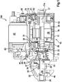
- Fig. 1 shows in a cross-sectional view an electrical machine 100 formed as a starting device or starter having a relay 42 arranged as a switching relay or an engagement relay.
- a starter housing 10 of the starting device comprises a cylindrical housing part 11 and a housing cover or lid 13, which are connected to each other by screws (not shown).
- the cylindrical housing part 11 is at the back side closes by said cover 13.
- a collar is formed, which is directed to an outside of the starting device.
- Inside the collar a bearing area is formed in which a back end 17a of an anchor shaft or driving shaft 17 of an electrical starter motor 18 is supported.
- An anchor of said electrical starter motor 18 is enumerated by reference number 19.
- the anchor 19 Radial outside of the anchor 19 several (Permanent-) magnets 20 of the electrical starter motor 18 are arranged at a wall of said housing part 11.
- a front end of said anchor shaft 17 is supported by a diameter reduced end area 22 of a blind hole 23 of a coaxial output shaft or a driven shaft 24.
- the back end of said driven shaft 24 is supported by a bearing shield 25, by which the housing part 11 is closed, and a collar 26 formed at said bearing shield 25.
- a planetary carrier 12 drives the driven shaft 24 on which a free-wheel gear 33 is arranged.
- An inner ring 34 of said free-wheel gear 33 has an appendix 35 (pinion gear or just pinion) at which external teeth 36 are formed.
- An outer ring 37 of the free-wheel gear 33 is connected to the driven shaft 24 by a steep thread 38.
- a so-called engaging spring 39 acts on said ring 37.
- the driving shaft 17 is at it's back end 17a secured in axial direction by a fixing mechanism.
- a brush plate 53 abuts on the cover 13, which is mounted to the cover 13 by screws.
- the brush plate 53 is formed as a one part brush plate 53.
- Brush holders, especially made of plastics, are mounted at the brush plate 53. Carbons are located in said brush holders, which abut by spring force at a commutator 63 that is arranged at the driving shaft 17. Carbons are connected to a cable shoe by pigtails.
- the cable shoe is connected to the relay 42 by a contact 68.
- Pigtails penetrate a sealing 70 located in an opening in the housing part 11.
- the brush plate 53 is mounted to the cover 13 by screws 62.
- connection assembly 200 formed as a bayonet locking 210 comprising a first element formed as a pinion 35 and a second element formed as a pinion shaft or driven shaft 24.
- the pinion 35 is formed integrated with the inner ring 34 of the free wheel gear 33 i.e. as a one-parted piece. Same or similar elements are referenced by same reference numerals. A detailed description of already described pieces or elements is omitted.
- Fig. 2 shows in a cross-sectional view the connection assembly 200 of the pinion 35 on the driven shaft 24 known from the prior art, which is formed as a bayonet locking 210 with an embodiment of an axial distance limitation 220.
- the axial distance limitation 220 is formed as an adjustable stop that is adjustable in axial direction A.
- the axial distance limitation 220 comprises a stop ring 221.
- the stop ring 221 has a surrounding groove 222.
- the axial distance limitation 220 comprises locking means 223 formed as a retaining ring 223a.
- the retaining ring 223a engages in said surrounding groove 222 of the stop ring 221. Further the retaining ring 223a is in contact with an inner circumferential wall of the pinion 35.
- Fig. 2 shows in a cross-sectional view the connection assembly 200 of the pinion 35 on the driven shaft 24 known from the prior art, which is formed as a bayonet locking 210 with an embodiment of an axial distance limitation 220.
- the inner circumferential wall has a surrounding groove in which the retaining ring 223a rests.
- the stop ring 221 serves as stopper when getting in contact with a front face 24a of the driven shaft 24.
- the position of the axial distance limitation 220 is located inside the pinion 35 such that an axial distance of the pinion 35 relatively to the driven shaft 24 is limited in a way the bayonet locking 210 may not open unintentionally and the driven shaft 24 cannot move out of the space 240 inside the pinion 35 defined by its inner circumferential wall.
- Said axial distance limitation 220 is formed (rotational-) symmetrically with regard to axis A so that there is no unbalance.
- the space 240 is formed as a through-going opening extending along the axial direction A. In this case the space 240 is formed as a cylindrical through-going opening.
- Fig. 3 shows in more details a cross-sectional view a connection assembly 200 of the pinion 35 on a driven shaft 24 according to Fig. 2 with another embodiment of an axial distance limitation 220.
- adjacent pieces or elements of the free wheel gear 33 like the annulus ring 37 or the engaging spring 39 are shown.
- An essential difference between Fig.2 and Fig. 3 is the embodiment of the axial distance limitation 220. While in Fig. 2 the axial distance limitation 220 is formed as a stop ring 221 fixed with separate locking means 223 in Fig. 3 the axial distance limitation 220 is formed as a screw 226 having an external thread 226a.
- the corresponding part of the circumferential wall where the axial distance locking 220 is located has an internal thread 226b for engaging with the external thread 226a.
- the driven shaft 24 contacts with its front face 24a the axial distance locking 220 such that there is no axial movement of the driven shaft 24 in direction towards the axial distance locking 220.
- Fig. 4 to 11 show several inventive and non-inventive embodiments of the axial distance limitation 220.
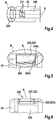
- Fig. 4 shows in a cross-sectional view a pinion 35 of the connection assembly 200 with a first embodiment of an axial distance limitation 220 marked with detail B.
- the axial distance limit 220 is shown in detail in Fig. 5 .
- Fig. 5 shows in a cross-sectional view a detail B of Fig. 4 showing more detailed the axial distance limitation 220.
- axial limitation distance 220 is formed as a screw 226 having the external thread 226a engaging with the internal thread 226b of the pinion 35, similar to the embodiment shown in Fig. 3 .
- the screw 226 is formed as a self-locking or self-impeding screw such that locking means 223 are integrated in said screw 226.
- Fig. 6 shows in a cross-sectional view the detail B of Fig. 4 showing a embodiment of the axial distance limitation 220 not belonging to the invention.
- the axial distance limitation 220 is formed as stop ring 221 having the circumferential or surrounding groove 222 in which the retaining ring 223a serving as locking means 223 is seated.
- the retaining ring 223a is also arranged in a circumferential or surrounding groove of the inner wall of the pinion 35 such that an axial locking is realized.
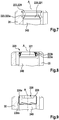
- Fig. 7 shows in a cross-sectional view the detail B of Fig. 4 showing another embodiment of the axial distance limitation 220 similar to Fig. 6 not belonging to the invention.
- the axial distance limitation 220 is similar to that shown in Fig. 6 but has additionally a disc-like deformation element 229 serving as additional locking means 223.
- the deformation element 229 is pressed in the space formed in the pinion 35. By this the deformation element 229 is seated press-fitted in the space 240 and serves as axial locking means 223.
- Fig. 8 shows in a cross-sectional view the detail B of Fig. 4 showing another embodiment of the axial distance limitation 220 similar to Fig. 6 and 7 not belonging to the invention.
- Main difference between the embodiments of Fig. 6 and 7 not belonging to the invention and that of Fig. 8 is, that the locking means 223 is realized by glue, adhesive, weld 223b and the like.
- Fig. Fig. 5 to 8 show axial distance limitations 210 comprising a stop ring 221
- Fig. 9 to 11 show axial distance limitations 220 comprising the screw 226.
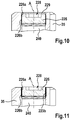
- Fig. 9 shows in a cross-sectional view the detail B of Fig. 4 showing another embodiment of the axial distance limitation 220 similar to Fig. 5 .
- the axial distance limitation 220 is formed as screw 226 having interference 228.
- the screw 226 may be locked through that interference 228 or with a self-curing resin, for example a microencapsulated epoxy. Alternatively a separate blocking member may be used.
- Fig. 10 shows in a cross-sectional view the detail B of Fig. 4 showing another embodiment of the axial distance limitation 220 similar to Fig. 5 and 9 . Additionally the axial distance limitation 220 compared to that in Fig. 9 comprises a deformation element 229 similar to that shown in Fig. 7 . The disc-like deformation element is press-fitted in the space 240 for axial locking the screw 226.
- Fig. 11 shows in a cross-sectional view the detail B of Fig. 4 showing another embodiment of the axial distance limitation 220 similar to Fig. 5 , 9 , and 10 . Similar to Fig. 8 the axial distance limitation 220 is integrally joint to the pinion 35 by weld, glue, adhesive 223b or the like.
- connection assembly 200 mounting of the connection assembly 200 is described.
- the ring-shaped circle symbolize the end of the pinion 35.
- the farther right elements of the right part of the figures symbolize the mounting procedure.
- the pinion 35 in Fig. 12 to 15 does not have any axial distance limitation 220.
- the axial distance limitation 220 is inserted.
- the distance of the ring-shaped circle to the remaining elements of the right part symbolize the distance of the front sided or front face 24a of the driven shaft 24 to the end of the pinion 35, where the axial distance limitation 220 is inserted.
- Fig. 12 shows schematically in a cross-sectional view and a longitudinal section the connection assembly 200 according to Fig. 2 in a first mounting step.
- the driven shaft 24 is partly inserted into the space 240 for housing the driven shaft 24 during operation, wherein the pinion 35 and the driven shaft 24 are axial not in contact with each other.
- the space 240 is not closed by an axial distance limitation 220.
- Guiding elements 35b of the pinion 35 in form of spline-like teeth 211 form an internal guiding path 35c.
- Guiding elements 24b formed as spline-like teeth of the driven shaft 24 form a counter guiding path 24c.
- Counter impacts 24d limit alternating counter guiding paths 24c, such that one counter guiding path 24c is open in direction towards pinion 35 and an adjacent counter guiding path 24c is locked in directions towards pinion 35.
- One rotation path 24e exists for connecting the counter guiding paths 24c with each other crosswise direction that is in a circumferential direction.
- guiding elements 35b start to slide between the counter impacts 24d in the counter guiding path 24c, such that the guiding paths 24c and 35c are engaging. Guiding paths 35c are spaced towards each other twice as far as the counter guiding paths 24c.
- Fig. 13 shows schematically in a cross-sectional view and a longitudinal section the connection assembly 200 according to Fig. 2 in a second mounting step.
- the driven shaft 24 is completely inserted into space 240.
- a pinion offset 35a and a driven shaft offset 24a forming a stopper are in contact with each other.
- the guiding elements 35b are moveable in a circumferential direction along the rotational path 24e.
- a rotational movement is shown in Fig.14 .
- Fig. 14 shows schematically in a cross-sectional view and a longitudinal section the connection assembly 200 according to Fig. 2 in a third mounting step.
- Driven shaft 24 is rotated relatively to pinion 35 in circumferential direction around axial direction A.
- rotation guiding elements 35b are moved along rotation path 24e until the engage or slide into next counter guiding path 24c.
- Next or adjacent counter guiding path 24c is limited in opposite direction to the direction of insertion by a counter stopper 24d. Movement of guiding elements 35b in direction toward counter impact 24d is shown in Fig. 15 .
- Fig. 15 shows schematically in a cross-sectional view and a longitudinal section the connection assembly 220 according to Fig. 2 in a fourth mounting step. Guiding elements 35b are moved along counter guiding path 24c in direction towards counter impact 24d. Corresponding to that driven shaft 24 is moved in opposite direction towards direction of insertion until a space for insertion of axial distance limitation 220 is given. When sufficient space for arranging axial distance limitation 220 is realized, axial distance limitation is inserted, as shown in Fig. 16 .
- Fig. 16 shows schematically in a cross-sectional view and a longitudinal section the connection assembly 220 according to Fig. 2 in a fifth mounting step.
- Axial distance limitation 220 is inserted and adjusted in axial direction A.
- Axial distance limitation 220 is finally locked for operating the connection assembly 200.
- Locked axial distance limitation 220 prevents a movement of driven shaft 24 against direction of insertion such that bayonet locking 210 is securely locked.
Landscapes
- Engineering & Computer Science (AREA)
- Chemical & Material Sciences (AREA)
- Combustion & Propulsion (AREA)
- Mechanical Engineering (AREA)
- General Engineering & Computer Science (AREA)
- Connection Of Motors, Electrical Generators, Mechanical Devices, And The Like (AREA)
- Gear Transmission (AREA)
- Manufacture Of Motors, Generators (AREA)
Description
- The invention relates to a method for mounting an electrical machine, in particular a generator or a starter mechanism as a starter, for starting a combustion engine.
- The present inventions starts out from a starter, in particular from a coaxial starter, for starting a combustion engine, in particular for motor and/or utility vehicles and a connection assembly for a force transmitting connection of two components of the connection assembly, as for example a push-on pinion connection for mounting a put-on pinion on a corresponding shaft according to the generic term of the independent claims.
- Object of the present invention are starters and starting mechanisms for vehicles having combustion engines comprising an electrical machine having an anchor and a commutator/collector, wherein the anchor has an anchor shaft and a corresponding anchor bearing. In particular an object of the present invention is a motor vehicle starter having an electric motor and an engaging system, for example according to a free ejective starter or a -type starter.
- Starter motors having a starting relay for vehicles with combustion engines are well known from prior art. Such starter motors comprise generally a direct current electric motor for starting the combustion engine.
- Starting mechanisms known from prior art comprise a free wheel gear(-box) having a rotatable pinion, which is supported with clearance. Corresponding starters for passenger cars and utility vehicles are well known. Those cars and vehicles comprise a starter pinion that is put on a pinion shaft, wherein the starter pinion is driven from the pinion shaft by a positive connection, in particular by a serration. Those starters are for example known as free ejective starters. In particular starters for start-stop-applications comprise this kind of push-on pinions, wherein such starters are arranged as nose-type starters. Usually an axial fixing of this kind of starters is formed by a spring-lock washer or retainer or a combination of retainer and stop ring. During mounting such pinions are put on the pinion shaft against a compression spring and in the following the retainer is mounted such that the compression spring forces the pinion against the retainer. By this the compression spring improves the track-in or engaging behavior and reduces a front side wear of the pinion and a gear ring. Further it is well known that those kinds of connections are realized by a bayonet locking. For preventing an unintentional unlocking of the bayonet locking an axial distance limitation is arranged. The well known axial distance limitation is formed as a washer having an U-shape, which after realizing the bayonet locking, is arranged on the pinion shaft between the components to connect. When the pinion shaft together with the U-shaped washer is rotating with high speed there is an unbalanced mass due to the asymmetric form of the washer. Due to that unbalanced mass and due to the high rotational speed of the pinion shaft, also called driven shaft, the washer tends to dismantle from the shaft such that a safe axial distance limitation is no longer guaranteed and the bayonet locking may unlock unintentionally.
- From
JP H03141817 A - According to the present invention there is provided a method for mounting an electric machine having the features of claim 1.
- The axial distance limitation may be used for different connection assemblies having different geometries, especially different length. Due to the adjustable stop being adjustable in an axial direction the stop matches to all kind of connection assemblies having different length. The adjustable stop is limited with regard to its width in axial direction but is adjustable with regard to its position relatively to one or both of the pinion or the pinion shaft. By this a safe axial limitation is guaranteed. In particular the electric machine or electrical machine is formed as a starter motor having a bayonet locking for realizing a pinion stop function. The bayonet locking and the dependent bayonet design are based on three main characteristics. First an internal spline on the starter motor pinion and/or in the overrunning clutch (short: ORC) that has half of the teeth specified for its diameter. Second an external spline at the driven shaft or pinion shaft has corresponding spline geometry in a front area that has half of the vacancies specified for its diameter. Third, after an assembly another component is used to prevent the internal spline to hit the back end of course.
- The bayonet locking and/or the bayonet design according to the present invention improve the system balancing and the strength regarding high speed conditions. Further the bayonet locking does not depend on the position of the ORC inside the starter. The assembly process can also be improved. Instead of using washers on the back part of the pinion a fixed stopper is used on the front part of the driving shaft. Thus an improved balancing and an improved strength against high speed conditions are realized. Further the solution is not dependant on the ORC position inside the starter motor. The assembly process is improved. Additionally the number of components is reduced. Last but not least the stop component can be designed to also perform a sealing function. The stop, stopper, or locker can be designed in several ways, which means that the assembly process is more flexible. In one embodiment the stop is formed as a stop ring or a screw. Thus the stop performs a fixation as well as a sealing function.
- By the measures of the dependent claims advantageous embodiments and benefits of the devices described in the main claims and the independent claims are realized.
- According to the invention a first component of said components of the connection assembly has a housing or a space for accommodating a second component of said components of the connection assembly for forming the connection assembly. The first component is a pinion, especially a starter or a starter motor pinion. The second component is a pinion shaft, also called driven shaft. The first component is put on the second component so that the second component is at least partly arranged in said first component. The inner geometry of said housing of the first component corresponds at least partly to a corresponding outer geometry of said second component accommodated in said housing. The housing is defined by a circumferential wall. Preferably the circumferential wall is formed as a cylindrical tube extending in axial direction.
- In an embodiment the first component has a bottom limiting the housing, wherein the bottom is formed as said adjustable stop. The bottom is thus adjustable in an axial direction to adjust the length of said housing. The bottom functions as a stopper for said second component. So the bottom limits the housing in axial direction, preferably at an end face of the housing.
- In an embodiment the housing is formed as a tube having openings at a front end and a rear end, preferably only at a front end and a rear end of the first component, which is formed as a pinion. The pinion shaft or driven shaft is inserted from the front end. The adjustable stop is located at the rear end. The pinion shaft is cylindrical. At its outer circumference there is an external spline forming several teeth. The housing is cylindrical. At its inner surface directed to the shaft there is an internal spline forming several teeth. The splines form a kind of spiral wherein adjacent teeth of the internal spline form paths for guiding teeth of the external spline. Some of the paths are limited in one direction such that a movement of the teeth of the external spline along these paths is limited. At this position the bayonet locking is in an operation position. For dissolving the components the shaft has to be moved in a reverse direction. For locking this movement, the axial distance limitation is arranged. Thus by having the axial distance limitation a locking of the bayonet locking is realized. The axial distance limitation has to be adjusted to the inserted shaft.
- Therefore in one further embodiment the adjustable stop is arranged in said tube, in particular at the rear end of said tube. As the adjustable stop is adjustable in an axial direction after insertion of the shaft the adjustable stop is moved in direction of the front end of the shaft until contact is reached or only a small gap is reached, such that a locking of the bayonet locking is realized. By arranging the adjustable stop inside the tube a small-sized solution is realized. Additionally no radial fixation is required as this fixation is done by the circumference of the tube.
- According to the invention the housing and/or the adjustable stop comprises locking means for locking the adjustable stop in an operating position. For preventing an unintentional unlocking of the bayonet locking, locking means are realized. That locking means may be from a kind of positive locking or form-fit, non-positive or force-fit, and/or locking by adhesive force, material engagement, integrally joint and/or substance locking. In one embodiment the locking means are self-locking means. In another embodiment additional means are arranged, for example glue. The locking means are in one embodiment arranged as one-way locking means that is locking means that are inseparable or not reversibly unlockable. In another embodiment the locking means are reversibly unlockable. The locking means may be formed as adjustable locking means that may be at least in one way adjustable in an axial direction.
- Also in one embodiment the housing and/or the adjustable stop comprises unlocking preventing means for preventing an unintentional unlocking of the adjustable stop from an operating position. Especially in case the locking means are arranged as reversible locking means additional unlocking preventing means may be disposed. The unlocking preventing means may be integrally formed with the locking means, e.g. as a thread. In another embodiment the unlocking preventing means may be formed separately from the locking means. Unlocking preventing means may be formed as resin, for example as microencapsulated resin that firmly bonds housing and locking means. Of course the unlocking preventing means and/or the stop may be connected with the front end of the shaft. The locking means and/or the unlocking means may be integrally formed. Thus the locking means and/or the unlocking means may be formed by a deformation element which deforms when in operation position which is the position such that a bayonet locking is realized.
- In yet another embodiment the means comprise at least one of the following: a self locking mechanism, a thread means, a press fit means, a glue means, a deformation means and/or any combination of the aforementioned.
- The second component of the connection assembly is put in the housing of the first component, rotated around the length axis and moved against the direction of insertion until reaching a stopper. Thus the connection assembly is in an operating position. For unlocking the connection assembly first movement in direction of insertion is required. When this movement is blocked unlocking is prevented. For unintentionally unlocking the axial distance limitation is arranged. After realizing the connection assembly in an operation position the axial distance limitation is arranged. Arrangement is done by moving the axial distance limitation in direction towards the second component in an axial direction. The axial distance limitation is placed inside the housing so that it is secured in a radial direction by the housing. Further, after reaching the operation position such that the bayonet locking is locked the axial distance limitation is fixed in this position, e.g. by suitable locking means. As the axial distance limitation is placed inside the housing the axial distance limitation my have a symmetric geometry. Thus the axial distance limitation, formed as an adjustable stop, being at least adjustable in axial direction, is formed symmetrically. A fixation of the adjustable stop may be by welding, gluing, screwing, bonding, and the like.
- According to the invention said axial distance limitation is axially locked such that during operation of said electrical machine said connection assembly is locked. The locking may be done by any means. For example the locking may be realized in a way that the locking is not reversible. In another embodiment the locking is reversible.
- Embodiments of the invention are depicted in the following drawings and described in detail in the accompanying description. The drawings show:
- Fig. 1
- in a cross-sectional view an electrical machine formed as a starting device,
- Fig. 2
- in a cross-sectional view a connection assembly of a pinion on a driven shaft formed as a bayonet locking with an embodiment of an axial distance limitation (prior art),
- Fig. 3
- in more details a cross-sectional view a connection assembly of a pinion on a driven shaft according to
Fig. 2 with another embodiment of an axial distance limitation, - Fig. 4
- in a cross-sectional view a pinion of a connection assembly with an embodiment of an axial distance limitation
- Fig. 5
- in a cross-sectional view a detail A of
Fig. 4 showing more detailed the axial distance limitation, - Fig. 6
- in a cross-sectional view the detail A of
Fig. 4 showing an embodiment of the axial distance limitation not belonging to the invention, - Fig. 7
- in a cross-sectional view the detail A of
Fig. 4 showing another embodiment of the axial distance limitation similar toFig. 6 not belonging to the invention, - Fig. 8
- in a cross-sectional view the detail A of
Fig. 4 showing another embodiment of the axial distance limitation similar toFig. 6 and7 not belonging to the invention, - Fig. 9
- in a cross-sectional view the detail A of
Fig. 4 showing another embodiment of the axial distance limitation similar toFig. 5 , - Fig. 10
- in a cross-sectional view the detail A of
Fig. 4 showing another embodiment of the axial distance limitation similar toFig. 5 and9 , - Fig. 11
- in a cross-sectional view the detail A of
Fig. 4 showing another embodiment of the axial distance limitation similar toFig. 5 ,9 , and10 , - Fig. 12
- schematically in a cross-sectional view and a longitudinal section the connection assembly according to
Fig. 2 in a first mounting step, - Fig. 13
- schematically in a cross-sectional view and a longitudinal section the connection assembly according to
Fig. 2 in a second mounting step, - Fig. 14
- schematically in a cross-sectional view and a longitudinal section the connection assembly according to
Fig. 2 in a third mounting step, - Fig. 15
- schematically in a cross-sectional view and a longitudinal section the connection assembly according to
Fig. 2 in a fourth mounting step, - Fig. 16
- schematically in a cross-sectional view and a longitudinal section the connection assembly according to
Fig. 2 in a fifth mounting step, -
Fig. 1 shows in a cross-sectional view anelectrical machine 100 formed as a starting device or starter having arelay 42 arranged as a switching relay or an engagement relay. Astarter housing 10 of the starting device comprises acylindrical housing part 11 and a housing cover orlid 13, which are connected to each other by screws (not shown). Thecylindrical housing part 11 is at the back side closes by saidcover 13. In a central area of the cover 13 a collar is formed, which is directed to an outside of the starting device. Inside the collar a bearing area is formed in which aback end 17a of an anchor shaft or drivingshaft 17 of anelectrical starter motor 18 is supported. An anchor of saidelectrical starter motor 18 is enumerated byreference number 19. Radial outside of theanchor 19 several (Permanent-)magnets 20 of theelectrical starter motor 18 are arranged at a wall of saidhousing part 11. A front end of saidanchor shaft 17 is supported by a diameter reducedend area 22 of ablind hole 23 of a coaxial output shaft or a drivenshaft 24. The back end of said drivenshaft 24 is supported by a bearingshield 25, by which thehousing part 11 is closed, and acollar 26 formed at said bearingshield 25. The drivingshaft 17 has a gearing 28 (sun gear) close to it's end directing to thebearing shield 25, in which planet gears 29 engage which also cog with an exterior, fixedannulus gear 30 of a planetary gear 31 (=reduction gear). - A
planetary carrier 12 drives the drivenshaft 24 on which a free-wheel gear 33 is arranged. Aninner ring 34 of said free-wheel gear 33 has an appendix 35 (pinion gear or just pinion) at whichexternal teeth 36 are formed. Anouter ring 37 of the free-wheel gear 33 is connected to the drivenshaft 24 by asteep thread 38. A so-calledengaging spring 39 acts on saidring 37. By axial movement of the free-wheel gear 33 theexternal teeth 36 may engage with anannular gear 40 of a combustion engine for initiating a starting process. This happens by means of said (engagement-)relay 42, in which during switching-on a current a magnet anchor via anappendix 43 deviates alever 44 that moves by a connectingmember 45, arranged between twodisks 46, the free-wheel gear 33 to the left. Thelever 44 is a two-armed lever, that is rotatable supported in abearing 49, fixed relatively to the housing, by pins 48. As this process is not further relevant for the invention it is only shortly described. - The driving
shaft 17 is at it'sback end 17a secured in axial direction by a fixing mechanism. Abrush plate 53 abuts on thecover 13, which is mounted to thecover 13 by screws. Thebrush plate 53 is formed as a onepart brush plate 53. Brush holders, especially made of plastics, are mounted at thebrush plate 53. Carbons are located in said brush holders, which abut by spring force at acommutator 63 that is arranged at the drivingshaft 17. Carbons are connected to a cable shoe by pigtails. The cable shoe is connected to therelay 42 by acontact 68. Pigtails penetrate a sealing 70 located in an opening in thehousing part 11. Thebrush plate 53 is mounted to thecover 13 byscrews 62. -
Fig. 2 to 16 show in different views and different level of details aconnection assembly 200 formed as a bayonet locking 210 comprising a first element formed as apinion 35 and a second element formed as a pinion shaft or drivenshaft 24. Thepinion 35 is formed integrated with theinner ring 34 of thefree wheel gear 33 i.e. as a one-parted piece. Same or similar elements are referenced by same reference numerals. A detailed description of already described pieces or elements is omitted. -
Fig. 2 shows in a cross-sectional view theconnection assembly 200 of thepinion 35 on the drivenshaft 24 known from the prior art, which is formed as a bayonet locking 210 with an embodiment of anaxial distance limitation 220. Theaxial distance limitation 220 is formed as an adjustable stop that is adjustable in axial direction A. Theaxial distance limitation 220 comprises astop ring 221. Thestop ring 221 has a surroundinggroove 222. Further theaxial distance limitation 220 comprises locking means 223 formed as a retainingring 223a. The retainingring 223a engages in said surroundinggroove 222 of thestop ring 221. Further the retainingring 223a is in contact with an inner circumferential wall of thepinion 35. As shown inFig. 2 the inner circumferential wall has a surrounding groove in which theretaining ring 223a rests. By this thestop ring 221 is locked or fixed in axial direction A. Thestop ring 221 serves as stopper when getting in contact with afront face 24a of the drivenshaft 24. The position of theaxial distance limitation 220 is located inside thepinion 35 such that an axial distance of thepinion 35 relatively to the drivenshaft 24 is limited in a way the bayonet locking 210 may not open unintentionally and the drivenshaft 24 cannot move out of thespace 240 inside thepinion 35 defined by its inner circumferential wall. Saidaxial distance limitation 220 is formed (rotational-) symmetrically with regard to axis A so that there is no unbalance. Thespace 240 is formed as a through-going opening extending along the axial direction A. In this case thespace 240 is formed as a cylindrical through-going opening. -
Fig. 3 shows in more details a cross-sectional view aconnection assembly 200 of thepinion 35 on a drivenshaft 24 according toFig. 2 with another embodiment of anaxial distance limitation 220. In thisFig. 3 adjacent pieces or elements of thefree wheel gear 33 like theannulus ring 37 or the engagingspring 39 are shown. An essential difference betweenFig.2 and Fig. 3 is the embodiment of theaxial distance limitation 220. While inFig. 2 theaxial distance limitation 220 is formed as astop ring 221 fixed with separate locking means 223 inFig. 3 theaxial distance limitation 220 is formed as ascrew 226 having anexternal thread 226a. Accordingly the corresponding part of the circumferential wall where the axial distance locking 220 is located has aninternal thread 226b for engaging with theexternal thread 226a. In this Fig the drivenshaft 24 contacts with itsfront face 24a the axial distance locking 220 such that there is no axial movement of the drivenshaft 24 in direction towards the axial distance locking 220. As will be described later the is also no axial movement of the drivenshaft 24 away from the axial distance locking 220 because of the bayonet locking 210. -
Fig. 4 to 11 show several inventive and non-inventive embodiments of theaxial distance limitation 220.Fig. 4 shows in a cross-sectional view apinion 35 of theconnection assembly 200 with a first embodiment of anaxial distance limitation 220 marked with detail B. Theaxial distance limit 220 is shown in detail inFig. 5 . On a circumferential wall surrounding thespace 240 for housing the drivenshaft 24 spline-like teeth 211 of the bayonet locking 210 are formed. -
Fig. 5 shows in a cross-sectional view a detail B ofFig. 4 showing more detailed theaxial distance limitation 220. As easily may be seen by thisFig. 5 axial limitation distance 220 is formed as ascrew 226 having theexternal thread 226a engaging with theinternal thread 226b of thepinion 35, similar to the embodiment shown inFig. 3 . Thescrew 226 is formed as a self-locking or self-impeding screw such that locking means 223 are integrated in saidscrew 226. -
Fig. 6 shows in a cross-sectional view the detail B ofFig. 4 showing a embodiment of theaxial distance limitation 220 not belonging to the invention. In this embodiment theaxial distance limitation 220 is formed asstop ring 221 having the circumferential or surroundinggroove 222 in which theretaining ring 223a serving as locking means 223 is seated. The retainingring 223a is also arranged in a circumferential or surrounding groove of the inner wall of thepinion 35 such that an axial locking is realized. -
Fig. 7 shows in a cross-sectional view the detail B ofFig. 4 showing another embodiment of theaxial distance limitation 220 similar toFig. 6 not belonging to the invention. Theaxial distance limitation 220 is similar to that shown inFig. 6 but has additionally a disc-like deformation element 229 serving as additional locking means 223. Thedeformation element 229 is pressed in the space formed in thepinion 35. By this thedeformation element 229 is seated press-fitted in thespace 240 and serves as axial locking means 223. -
Fig. 8 shows in a cross-sectional view the detail B ofFig. 4 showing another embodiment of theaxial distance limitation 220 similar toFig. 6 and7 not belonging to the invention. Main difference between the embodiments ofFig. 6 and7 not belonging to the invention and that ofFig. 8 is, that the locking means 223 is realized by glue, adhesive,weld 223b and the like. - Wherein Fig.
Fig. 5 to 8 showaxial distance limitations 210 comprising astop ring 221Fig. 9 to 11 showaxial distance limitations 220 comprising thescrew 226. -
Fig. 9 shows in a cross-sectional view the detail B ofFig. 4 showing another embodiment of theaxial distance limitation 220 similar toFig. 5 . Theaxial distance limitation 220 is formed asscrew 226 havinginterference 228. Thescrew 226 may be locked through thatinterference 228 or with a self-curing resin, for example a microencapsulated epoxy. Alternatively a separate blocking member may be used. -
Fig. 10 shows in a cross-sectional view the detail B ofFig. 4 showing another embodiment of theaxial distance limitation 220 similar toFig. 5 and9 . Additionally theaxial distance limitation 220 compared to that inFig. 9 comprises adeformation element 229 similar to that shown inFig. 7 . The disc-like deformation element is press-fitted in thespace 240 for axial locking thescrew 226. -
Fig. 11 shows in a cross-sectional view the detail B ofFig. 4 showing another embodiment of theaxial distance limitation 220 similar toFig. 5 ,9 , and10 . Similar toFig. 8 theaxial distance limitation 220 is integrally joint to thepinion 35 by weld, glue, adhesive 223b or the like. - In the following with regard to
Fig. 12 to 16 mounting of theconnection assembly 200 is described. On the right part of each figure the ring-shaped circle symbolize the end of thepinion 35. The farther right elements of the right part of the figures symbolize the mounting procedure. As can be seen by the figures, thepinion 35 inFig. 12 to 15 does not have anyaxial distance limitation 220. InFig. 16 theaxial distance limitation 220 is inserted. The distance of the ring-shaped circle to the remaining elements of the right part symbolize the distance of the front sided orfront face 24a of the drivenshaft 24 to the end of thepinion 35, where theaxial distance limitation 220 is inserted. -
Fig. 12 shows schematically in a cross-sectional view and a longitudinal section theconnection assembly 200 according toFig. 2 in a first mounting step. In this step or condition the drivenshaft 24 is partly inserted into thespace 240 for housing the drivenshaft 24 during operation, wherein thepinion 35 and the drivenshaft 24 are axial not in contact with each other. Thespace 240 is not closed by anaxial distance limitation 220. Guidingelements 35b of thepinion 35 in form of spline-like teeth 211 form aninternal guiding path 35c. Guidingelements 24b formed as spline-like teeth of the drivenshaft 24 form acounter guiding path 24c. Counter impacts 24d limit alternatingcounter guiding paths 24c, such that onecounter guiding path 24c is open in direction towardspinion 35 and an adjacentcounter guiding path 24c is locked in directions towardspinion 35. Onerotation path 24e exists for connecting thecounter guiding paths 24c with each other crosswise direction that is in a circumferential direction. In the step shown inFig. 12 guidingelements 35b start to slide between the counter impacts 24d in thecounter guiding path 24c, such that the guidingpaths paths 35c are spaced towards each other twice as far as thecounter guiding paths 24c. -
Fig. 13 shows schematically in a cross-sectional view and a longitudinal section theconnection assembly 200 according toFig. 2 in a second mounting step. In this step the drivenshaft 24 is completely inserted intospace 240. A pinion offset 35a and a driven shaft offset 24a forming a stopper are in contact with each other. The guidingelements 35b are moveable in a circumferential direction along therotational path 24e. A rotational movement is shown inFig.14 . -
Fig. 14 shows schematically in a cross-sectional view and a longitudinal section theconnection assembly 200 according toFig. 2 in a third mounting step. Drivenshaft 24 is rotated relatively to pinion 35 in circumferential direction around axial direction A. In this step ofrotation guiding elements 35b are moved alongrotation path 24e until the engage or slide into nextcounter guiding path 24c. Next or adjacentcounter guiding path 24c is limited in opposite direction to the direction of insertion by acounter stopper 24d. Movement of guidingelements 35b in direction towardcounter impact 24d is shown inFig. 15 . -
Fig. 15 shows schematically in a cross-sectional view and a longitudinal section theconnection assembly 220 according toFig. 2 in a fourth mounting step. Guidingelements 35b are moved along counter guidingpath 24c in direction towardscounter impact 24d. Corresponding to that drivenshaft 24 is moved in opposite direction towards direction of insertion until a space for insertion ofaxial distance limitation 220 is given. When sufficient space for arrangingaxial distance limitation 220 is realized, axial distance limitation is inserted, as shown inFig. 16 . -
Fig. 16 shows schematically in a cross-sectional view and a longitudinal section theconnection assembly 220 according toFig. 2 in a fifth mounting step.Axial distance limitation 220 is inserted and adjusted in axial direction A.Axial distance limitation 220 is finally locked for operating theconnection assembly 200. Lockedaxial distance limitation 220 prevents a movement of drivenshaft 24 against direction of insertion such that bayonet locking 210 is securely locked.
Claims (6)
- Method for mounting an electrical machine (100), in particular a generator or a starter mechanism as a starter, for starting a combustion engine, comprising a connection assembly (200) for a force transmitting connection of a pinion and a pinion shaft of the connection assembly (200) having a bayonet locking (210) with an axial distance limitation (220) for preventing an unintentional opening of the bayonet locking (210), wherein the pinion of the connection assembly (200) has a housing (240) for accommodating the shaft of the connection assembly (200) for forming the connection assembly (200),
comprising the steps:arranging of the axial distance limitation (220) inside the housing (240) of the pinion of the connection assembly (200),after the connection assembly (200) is arranged in an operating position, said axial distance limitation (220) is moved in an axial direction such that the bayonet locking (210) is locked in said operating position for preventing an unintentional unlocking of the connection assembly (200), wherein the axial distance limitation (220) is adjusted to the inserted shaft, and wherein said axial distance limitation (220) is axially locked such that during operation of said electrical machine (100) said connection assembly (200) is locked,wherein said axial distance limitation (220) is formed as an adjustable stop that is adjustable with regard to its position relatively to one or both components at least in axial direction (A),wherein the housing (240) of the pinion and/or the adjustable stop comprise locking means (223) for locking the adjustable stop in the operating position. - Method according to claim 1, characterized in, that
the pinion has a bottom limiting the housing (240), wherein the bottom is formed as said adjustable stop. - Method according to one of claims 1 to 2, characterized in, that the housing (240) is formed as a tube having openings at a front end and a rear end.
- Method according to one of the proceeding claims, characterized in, that the locking means (223) comprise at least one of the following: a self locking mechanism, thread means, press fit means, glue means, deformation means and or any combination of the aforementioned.
- Method according to one of the proceeding claims, characterized in, that the housing (240) and/or the adjustable stop comprises unlocking preventing means for preventing an unintentional unlocking of the adjustable stop from an operating position.
- Method according to claim 5, characterized in, that
the unlocking preventing means comprise at least one of the following: a self locking mechanism, thread means, press fit means, glue means, deformation means and or any combination of the aforementioned.
Priority Applications (4)
| Application Number | Priority Date | Filing Date | Title |
|---|---|---|---|
| EP13165873.4A EP2799707B1 (en) | 2013-04-30 | 2013-04-30 | Method for mounting an electrical machine |
| HUE13165873A HUE057946T2 (en) | 2013-04-30 | 2013-04-30 | Method for mounting an electrical machine |
| CN201410322801.XA CN104131928B (en) | 2013-04-30 | 2014-04-29 | Motor and the method for installing motor |
| BR102014010369A BR102014010369A8 (en) | 2013-04-30 | 2014-04-30 | ELECTRIC MACHINE AND METHOD FOR ASSEMBLING AN ELECTRIC MACHINE |
Applications Claiming Priority (1)
| Application Number | Priority Date | Filing Date | Title |
|---|---|---|---|
| EP13165873.4A EP2799707B1 (en) | 2013-04-30 | 2013-04-30 | Method for mounting an electrical machine |
Publications (2)
| Publication Number | Publication Date |
|---|---|
| EP2799707A1 EP2799707A1 (en) | 2014-11-05 |
| EP2799707B1 true EP2799707B1 (en) | 2021-12-01 |
Family
ID=48190336
Family Applications (1)
| Application Number | Title | Priority Date | Filing Date |
|---|---|---|---|
| EP13165873.4A Not-in-force EP2799707B1 (en) | 2013-04-30 | 2013-04-30 | Method for mounting an electrical machine |
Country Status (4)
| Country | Link |
|---|---|
| EP (1) | EP2799707B1 (en) |
| CN (1) | CN104131928B (en) |
| BR (1) | BR102014010369A8 (en) |
| HU (1) | HUE057946T2 (en) |
Families Citing this family (3)
| Publication number | Priority date | Publication date | Assignee | Title |
|---|---|---|---|---|
| WO2017216889A1 (en) * | 2016-06-15 | 2017-12-21 | 三菱電機株式会社 | Internal-combustion engine starting device |
| CN107387286A (en) * | 2017-08-25 | 2017-11-24 | 浙江瑞申汽配有限公司 | Energy-saving compact automobile starter |
| CN112684340B (en) * | 2021-01-08 | 2022-08-23 | 苏州工业园区泰格电子科技有限公司 | Detection device for detecting whether motor can be started normally |
Family Cites Families (5)
| Publication number | Priority date | Publication date | Assignee | Title |
|---|---|---|---|---|
| JP2537282B2 (en) * | 1989-10-28 | 1996-09-25 | 株式会社日立製作所 | Starter |
| FR2920837B1 (en) * | 2007-09-10 | 2013-08-02 | Valeo Equip Electr Moteur | ROTATING ELECTRIC MACHINE, IN PARTICULAR A STARTER |
| DE102010030716B4 (en) * | 2010-06-30 | 2015-09-17 | Robert Bosch Gmbh | starter |
| DE102010030724B4 (en) * | 2010-06-30 | 2019-07-25 | Seg Automotive Germany Gmbh | Starting device and method for producing a stop for a displaceable pinion of a starting device arranged on a shaft |
| DE102010030727B4 (en) * | 2010-06-30 | 2016-03-31 | Robert Bosch Gmbh | Starting device and method for producing a stop for a displaceable pinion of a starting device arranged on a shaft |
-
2013
- 2013-04-30 EP EP13165873.4A patent/EP2799707B1/en not_active Not-in-force
- 2013-04-30 HU HUE13165873A patent/HUE057946T2/en unknown
-
2014
- 2014-04-29 CN CN201410322801.XA patent/CN104131928B/en not_active Expired - Fee Related
- 2014-04-30 BR BR102014010369A patent/BR102014010369A8/en not_active Application Discontinuation
Non-Patent Citations (1)
| Title |
|---|
| None * |
Also Published As
| Publication number | Publication date |
|---|---|
| EP2799707A1 (en) | 2014-11-05 |
| BR102014010369A8 (en) | 2018-08-14 |
| BR102014010369A2 (en) | 2015-10-13 |
| CN104131928A (en) | 2014-11-05 |
| CN104131928B (en) | 2017-12-26 |
| HUE057946T2 (en) | 2022-06-28 |
Similar Documents
| Publication | Publication Date | Title |
|---|---|---|
| US9222567B2 (en) | Asymmetric toothing | |
| CN104234901B (en) | Starter | |
| US9617964B2 (en) | Starting device for an internal combustion engine | |
| CN103023189B (en) | The method of the extending end bearing device of motor, particularly starting device and manufacture motor | |
| CN103133209B (en) | Starting arrangement | |
| EP2799707A1 (en) | Electrical machine and method for mounting an electrical machine | |
| US9920734B2 (en) | Starter | |
| JP2010084769A (en) | Starting device | |
| ZA200302200B (en) | Starter. | |
| CN103443444B (en) | Starter with overload protection | |
| CN103256164B (en) | Motor and installation method thereof | |
| JP2012087765A (en) | Starter | |
| CN102444523A (en) | Starter for a combustion engine | |
| PL223643B1 (en) | Boot device and the boot device mounting method | |
| JP5535704B2 (en) | Starter | |
| US8661924B2 (en) | Starter with rock back and oscillation abosrbers | |
| CN104254685B (en) | Starter | |
| US20120125149A1 (en) | Motor starter including an armature having an integral drive system | |
| CN104179615B (en) | Motor and the method for manufacturing and/or running the motor | |
| KR102017638B1 (en) | starter | |
| CN102650252A (en) | Fixed holding disc | |
| EP2778387B1 (en) | Electrical machine and method for manufacturing and/or mounting an electrical machine | |
| US20200231201A1 (en) | Steering Systems for a Vehicle | |
| CN104728016B (en) | Freewheel with slip-clutch | |
| CN104131937B (en) | Starting device used for internal combustion engine |
Legal Events
| Date | Code | Title | Description |
|---|---|---|---|
| PUAI | Public reference made under article 153(3) epc to a published international application that has entered the european phase |
Free format text: ORIGINAL CODE: 0009012 |
|
| 17P | Request for examination filed |
Effective date: 20130430 |
|
| AK | Designated contracting states |
Kind code of ref document: A1 Designated state(s): AL AT BE BG CH CY CZ DE DK EE ES FI FR GB GR HR HU IE IS IT LI LT LU LV MC MK MT NL NO PL PT RO RS SE SI SK SM TR |
|
| AX | Request for extension of the european patent |
Extension state: BA ME |
|
| R17P | Request for examination filed (corrected) |
Effective date: 20150506 |
|
| RBV | Designated contracting states (corrected) |
Designated state(s): AL AT BE BG CH CY CZ DE DK EE ES FI FR GB GR HR HU IE IS IT LI LT LU LV MC MK MT NL NO PL PT RO RS SE SI SK SM TR |
|
| RAP1 | Party data changed (applicant data changed or rights of an application transferred) |
Owner name: SEG AUTOMOTIVE GERMANY GMBH |
|
| STAA | Information on the status of an ep patent application or granted ep patent |
Free format text: STATUS: EXAMINATION IS IN PROGRESS |
|
| 17Q | First examination report despatched |
Effective date: 20200421 |
|
| RIC1 | Information provided on ipc code assigned before grant |
Ipc: F02N 15/00 20060101AFI20200924BHEP Ipc: F02N 15/06 20060101ALI20200924BHEP Ipc: F02N 11/00 20060101ALN20200924BHEP Ipc: F02N 15/04 20060101ALN20200924BHEP Ipc: F02N 15/02 20060101ALN20200924BHEP |
|
| RIC1 | Information provided on ipc code assigned before grant |
Ipc: F02N 15/00 20060101AFI20201015BHEP Ipc: F02N 15/02 20060101ALN20201015BHEP Ipc: F02N 11/00 20060101ALN20201015BHEP Ipc: F02N 15/06 20060101ALI20201015BHEP Ipc: F02N 15/04 20060101ALN20201015BHEP |
|
| RIC1 | Information provided on ipc code assigned before grant |
Ipc: F02N 15/00 20060101AFI20210513BHEP Ipc: F02N 15/06 20060101ALI20210513BHEP Ipc: F02N 11/00 20060101ALN20210513BHEP Ipc: F02N 15/04 20060101ALN20210513BHEP Ipc: F02N 15/02 20060101ALN20210513BHEP |
|
| GRAP | Despatch of communication of intention to grant a patent |
Free format text: ORIGINAL CODE: EPIDOSNIGR1 |
|
| STAA | Information on the status of an ep patent application or granted ep patent |
Free format text: STATUS: GRANT OF PATENT IS INTENDED |
|
| INTG | Intention to grant announced |
Effective date: 20210623 |
|
| GRAS | Grant fee paid |
Free format text: ORIGINAL CODE: EPIDOSNIGR3 |
|
| GRAA | (expected) grant |
Free format text: ORIGINAL CODE: 0009210 |
|
| STAA | Information on the status of an ep patent application or granted ep patent |
Free format text: STATUS: THE PATENT HAS BEEN GRANTED |
|
| AK | Designated contracting states |
Kind code of ref document: B1 Designated state(s): AL AT BE BG CH CY CZ DE DK EE ES FI FR GB GR HR HU IE IS IT LI LT LU LV MC MK MT NL NO PL PT RO RS SE SI SK SM TR |
|
| REG | Reference to a national code |
Ref country code: GB Ref legal event code: FG4D |
|
| REG | Reference to a national code |
Ref country code: AT Ref legal event code: REF Ref document number: 1451987 Country of ref document: AT Kind code of ref document: T Effective date: 20211215 Ref country code: CH Ref legal event code: EP |
|
| REG | Reference to a national code |
Ref country code: IE Ref legal event code: FG4D |
|
| REG | Reference to a national code |
Ref country code: DE Ref legal event code: R096 Ref document number: 602013080239 Country of ref document: DE |
|
| REG | Reference to a national code |
Ref country code: LT Ref legal event code: MG9D |
|
| REG | Reference to a national code |
Ref country code: NL Ref legal event code: MP Effective date: 20211201 |
|
| REG | Reference to a national code |
Ref country code: AT Ref legal event code: MK05 Ref document number: 1451987 Country of ref document: AT Kind code of ref document: T Effective date: 20211201 |
|
| PG25 | Lapsed in a contracting state [announced via postgrant information from national office to epo] |
Ref country code: RS Free format text: LAPSE BECAUSE OF FAILURE TO SUBMIT A TRANSLATION OF THE DESCRIPTION OR TO PAY THE FEE WITHIN THE PRESCRIBED TIME-LIMIT Effective date: 20211201 Ref country code: LT Free format text: LAPSE BECAUSE OF FAILURE TO SUBMIT A TRANSLATION OF THE DESCRIPTION OR TO PAY THE FEE WITHIN THE PRESCRIBED TIME-LIMIT Effective date: 20211201 Ref country code: FI Free format text: LAPSE BECAUSE OF FAILURE TO SUBMIT A TRANSLATION OF THE DESCRIPTION OR TO PAY THE FEE WITHIN THE PRESCRIBED TIME-LIMIT Effective date: 20211201 Ref country code: BG Free format text: LAPSE BECAUSE OF FAILURE TO SUBMIT A TRANSLATION OF THE DESCRIPTION OR TO PAY THE FEE WITHIN THE PRESCRIBED TIME-LIMIT Effective date: 20220301 Ref country code: AT Free format text: LAPSE BECAUSE OF FAILURE TO SUBMIT A TRANSLATION OF THE DESCRIPTION OR TO PAY THE FEE WITHIN THE PRESCRIBED TIME-LIMIT Effective date: 20211201 |
|
| PG25 | Lapsed in a contracting state [announced via postgrant information from national office to epo] |
Ref country code: SE Free format text: LAPSE BECAUSE OF FAILURE TO SUBMIT A TRANSLATION OF THE DESCRIPTION OR TO PAY THE FEE WITHIN THE PRESCRIBED TIME-LIMIT Effective date: 20211201 Ref country code: PL Free format text: LAPSE BECAUSE OF FAILURE TO SUBMIT A TRANSLATION OF THE DESCRIPTION OR TO PAY THE FEE WITHIN THE PRESCRIBED TIME-LIMIT Effective date: 20211201 Ref country code: NO Free format text: LAPSE BECAUSE OF FAILURE TO SUBMIT A TRANSLATION OF THE DESCRIPTION OR TO PAY THE FEE WITHIN THE PRESCRIBED TIME-LIMIT Effective date: 20220301 Ref country code: LV Free format text: LAPSE BECAUSE OF FAILURE TO SUBMIT A TRANSLATION OF THE DESCRIPTION OR TO PAY THE FEE WITHIN THE PRESCRIBED TIME-LIMIT Effective date: 20211201 Ref country code: HR Free format text: LAPSE BECAUSE OF FAILURE TO SUBMIT A TRANSLATION OF THE DESCRIPTION OR TO PAY THE FEE WITHIN THE PRESCRIBED TIME-LIMIT Effective date: 20211201 Ref country code: GR Free format text: LAPSE BECAUSE OF FAILURE TO SUBMIT A TRANSLATION OF THE DESCRIPTION OR TO PAY THE FEE WITHIN THE PRESCRIBED TIME-LIMIT Effective date: 20220302 Ref country code: ES Free format text: LAPSE BECAUSE OF FAILURE TO SUBMIT A TRANSLATION OF THE DESCRIPTION OR TO PAY THE FEE WITHIN THE PRESCRIBED TIME-LIMIT Effective date: 20211201 |
|
| REG | Reference to a national code |
Ref country code: HU Ref legal event code: AG4A Ref document number: E057946 Country of ref document: HU |
|
| PG25 | Lapsed in a contracting state [announced via postgrant information from national office to epo] |
Ref country code: NL Free format text: LAPSE BECAUSE OF FAILURE TO SUBMIT A TRANSLATION OF THE DESCRIPTION OR TO PAY THE FEE WITHIN THE PRESCRIBED TIME-LIMIT Effective date: 20211201 |
|
| PG25 | Lapsed in a contracting state [announced via postgrant information from national office to epo] |
Ref country code: SM Free format text: LAPSE BECAUSE OF FAILURE TO SUBMIT A TRANSLATION OF THE DESCRIPTION OR TO PAY THE FEE WITHIN THE PRESCRIBED TIME-LIMIT Effective date: 20211201 Ref country code: SK Free format text: LAPSE BECAUSE OF FAILURE TO SUBMIT A TRANSLATION OF THE DESCRIPTION OR TO PAY THE FEE WITHIN THE PRESCRIBED TIME-LIMIT Effective date: 20211201 Ref country code: RO Free format text: LAPSE BECAUSE OF FAILURE TO SUBMIT A TRANSLATION OF THE DESCRIPTION OR TO PAY THE FEE WITHIN THE PRESCRIBED TIME-LIMIT Effective date: 20211201 Ref country code: PT Free format text: LAPSE BECAUSE OF FAILURE TO SUBMIT A TRANSLATION OF THE DESCRIPTION OR TO PAY THE FEE WITHIN THE PRESCRIBED TIME-LIMIT Effective date: 20220401 Ref country code: EE Free format text: LAPSE BECAUSE OF FAILURE TO SUBMIT A TRANSLATION OF THE DESCRIPTION OR TO PAY THE FEE WITHIN THE PRESCRIBED TIME-LIMIT Effective date: 20211201 Ref country code: CZ Free format text: LAPSE BECAUSE OF FAILURE TO SUBMIT A TRANSLATION OF THE DESCRIPTION OR TO PAY THE FEE WITHIN THE PRESCRIBED TIME-LIMIT Effective date: 20211201 |
|
| PGFP | Annual fee paid to national office [announced via postgrant information from national office to epo] |
Ref country code: HU Payment date: 20220426 Year of fee payment: 10 Ref country code: FR Payment date: 20220420 Year of fee payment: 10 Ref country code: DE Payment date: 20220422 Year of fee payment: 10 |
|
| REG | Reference to a national code |
Ref country code: DE Ref legal event code: R097 Ref document number: 602013080239 Country of ref document: DE |
|
| PG25 | Lapsed in a contracting state [announced via postgrant information from national office to epo] |
Ref country code: IS Free format text: LAPSE BECAUSE OF FAILURE TO SUBMIT A TRANSLATION OF THE DESCRIPTION OR TO PAY THE FEE WITHIN THE PRESCRIBED TIME-LIMIT Effective date: 20220401 |
|
| PLBE | No opposition filed within time limit |
Free format text: ORIGINAL CODE: 0009261 |
|
| STAA | Information on the status of an ep patent application or granted ep patent |
Free format text: STATUS: NO OPPOSITION FILED WITHIN TIME LIMIT |
|
| PG25 | Lapsed in a contracting state [announced via postgrant information from national office to epo] |
Ref country code: DK Free format text: LAPSE BECAUSE OF FAILURE TO SUBMIT A TRANSLATION OF THE DESCRIPTION OR TO PAY THE FEE WITHIN THE PRESCRIBED TIME-LIMIT Effective date: 20211201 Ref country code: AL Free format text: LAPSE BECAUSE OF FAILURE TO SUBMIT A TRANSLATION OF THE DESCRIPTION OR TO PAY THE FEE WITHIN THE PRESCRIBED TIME-LIMIT Effective date: 20211201 |
|
| 26N | No opposition filed |
Effective date: 20220902 |
|
| PG25 | Lapsed in a contracting state [announced via postgrant information from national office to epo] |
Ref country code: SI Free format text: LAPSE BECAUSE OF FAILURE TO SUBMIT A TRANSLATION OF THE DESCRIPTION OR TO PAY THE FEE WITHIN THE PRESCRIBED TIME-LIMIT Effective date: 20211201 |
|
| REG | Reference to a national code |
Ref country code: CH Ref legal event code: PL |
|
| GBPC | Gb: european patent ceased through non-payment of renewal fee |
Effective date: 20220430 |
|
| REG | Reference to a national code |
Ref country code: BE Ref legal event code: MM Effective date: 20220430 |
|
| PG25 | Lapsed in a contracting state [announced via postgrant information from national office to epo] |
Ref country code: MC Free format text: LAPSE BECAUSE OF FAILURE TO SUBMIT A TRANSLATION OF THE DESCRIPTION OR TO PAY THE FEE WITHIN THE PRESCRIBED TIME-LIMIT Effective date: 20211201 Ref country code: LU Free format text: LAPSE BECAUSE OF NON-PAYMENT OF DUE FEES Effective date: 20220430 Ref country code: LI Free format text: LAPSE BECAUSE OF NON-PAYMENT OF DUE FEES Effective date: 20220430 Ref country code: GB Free format text: LAPSE BECAUSE OF NON-PAYMENT OF DUE FEES Effective date: 20220430 Ref country code: CH Free format text: LAPSE BECAUSE OF NON-PAYMENT OF DUE FEES Effective date: 20220430 |
|
| PG25 | Lapsed in a contracting state [announced via postgrant information from national office to epo] |
Ref country code: BE Free format text: LAPSE BECAUSE OF NON-PAYMENT OF DUE FEES Effective date: 20220430 |
|
| PG25 | Lapsed in a contracting state [announced via postgrant information from national office to epo] |
Ref country code: IE Free format text: LAPSE BECAUSE OF NON-PAYMENT OF DUE FEES Effective date: 20220430 |
|
| PG25 | Lapsed in a contracting state [announced via postgrant information from national office to epo] |
Ref country code: IT Free format text: LAPSE BECAUSE OF FAILURE TO SUBMIT A TRANSLATION OF THE DESCRIPTION OR TO PAY THE FEE WITHIN THE PRESCRIBED TIME-LIMIT Effective date: 20211201 |
|
| REG | Reference to a national code |
Ref country code: DE Ref legal event code: R119 Ref document number: 602013080239 Country of ref document: DE |
|
| PG25 | Lapsed in a contracting state [announced via postgrant information from national office to epo] |
Ref country code: HU Free format text: LAPSE BECAUSE OF NON-PAYMENT OF DUE FEES Effective date: 20230501 Ref country code: FR Free format text: LAPSE BECAUSE OF NON-PAYMENT OF DUE FEES Effective date: 20230430 Ref country code: DE Free format text: LAPSE BECAUSE OF NON-PAYMENT OF DUE FEES Effective date: 20231103 |
|
| PG25 | Lapsed in a contracting state [announced via postgrant information from national office to epo] |
Ref country code: MK Free format text: LAPSE BECAUSE OF FAILURE TO SUBMIT A TRANSLATION OF THE DESCRIPTION OR TO PAY THE FEE WITHIN THE PRESCRIBED TIME-LIMIT Effective date: 20211201 Ref country code: CY Free format text: LAPSE BECAUSE OF FAILURE TO SUBMIT A TRANSLATION OF THE DESCRIPTION OR TO PAY THE FEE WITHIN THE PRESCRIBED TIME-LIMIT Effective date: 20211201 |
|
| PG25 | Lapsed in a contracting state [announced via postgrant information from national office to epo] |
Ref country code: TR Free format text: LAPSE BECAUSE OF FAILURE TO SUBMIT A TRANSLATION OF THE DESCRIPTION OR TO PAY THE FEE WITHIN THE PRESCRIBED TIME-LIMIT Effective date: 20211201 |
|
| PG25 | Lapsed in a contracting state [announced via postgrant information from national office to epo] |
Ref country code: MT Free format text: LAPSE BECAUSE OF FAILURE TO SUBMIT A TRANSLATION OF THE DESCRIPTION OR TO PAY THE FEE WITHIN THE PRESCRIBED TIME-LIMIT Effective date: 20211201 |