EP2796914A2 - Zoom lens and image pickup device including the same - Google Patents
Zoom lens and image pickup device including the same Download PDFInfo
- Publication number
- EP2796914A2 EP2796914A2 EP14165818.7A EP14165818A EP2796914A2 EP 2796914 A2 EP2796914 A2 EP 2796914A2 EP 14165818 A EP14165818 A EP 14165818A EP 2796914 A2 EP2796914 A2 EP 2796914A2
- Authority
- EP
- European Patent Office
- Prior art keywords
- lens unit
- lens
- refractive power
- zoom
- negative refractive
- Prior art date
- Legal status (The legal status is an assumption and is not a legal conclusion. Google has not performed a legal analysis and makes no representation as to the accuracy of the status listed.)
- Granted
Links
Images


Classifications
-
- G—PHYSICS
- G02—OPTICS
- G02B—OPTICAL ELEMENTS, SYSTEMS OR APPARATUS
- G02B15/00—Optical objectives with means for varying the magnification
- G02B15/14—Optical objectives with means for varying the magnification by axial movement of one or more lenses or groups of lenses relative to the image plane for continuously varying the equivalent focal length of the objective
- G02B15/16—Optical objectives with means for varying the magnification by axial movement of one or more lenses or groups of lenses relative to the image plane for continuously varying the equivalent focal length of the objective with interdependent non-linearly related movements between one lens or lens group, and another lens or lens group
- G02B15/177—Optical objectives with means for varying the magnification by axial movement of one or more lenses or groups of lenses relative to the image plane for continuously varying the equivalent focal length of the objective with interdependent non-linearly related movements between one lens or lens group, and another lens or lens group having a negative front lens or group of lenses
-
- G—PHYSICS
- G02—OPTICS
- G02B—OPTICAL ELEMENTS, SYSTEMS OR APPARATUS
- G02B15/00—Optical objectives with means for varying the magnification
- G02B15/14—Optical objectives with means for varying the magnification by axial movement of one or more lenses or groups of lenses relative to the image plane for continuously varying the equivalent focal length of the objective
- G02B15/144—Optical objectives with means for varying the magnification by axial movement of one or more lenses or groups of lenses relative to the image plane for continuously varying the equivalent focal length of the objective having four groups only
- G02B15/1445—Optical objectives with means for varying the magnification by axial movement of one or more lenses or groups of lenses relative to the image plane for continuously varying the equivalent focal length of the objective having four groups only the first group being negative
- G02B15/144503—Optical objectives with means for varying the magnification by axial movement of one or more lenses or groups of lenses relative to the image plane for continuously varying the equivalent focal length of the objective having four groups only the first group being negative arranged -+--
-
- G—PHYSICS
- G02—OPTICS
- G02B—OPTICAL ELEMENTS, SYSTEMS OR APPARATUS
- G02B15/00—Optical objectives with means for varying the magnification
- G02B15/14—Optical objectives with means for varying the magnification by axial movement of one or more lenses or groups of lenses relative to the image plane for continuously varying the equivalent focal length of the objective
- G02B15/144—Optical objectives with means for varying the magnification by axial movement of one or more lenses or groups of lenses relative to the image plane for continuously varying the equivalent focal length of the objective having four groups only
- G02B15/1445—Optical objectives with means for varying the magnification by axial movement of one or more lenses or groups of lenses relative to the image plane for continuously varying the equivalent focal length of the objective having four groups only the first group being negative
- G02B15/144507—Optical objectives with means for varying the magnification by axial movement of one or more lenses or groups of lenses relative to the image plane for continuously varying the equivalent focal length of the objective having four groups only the first group being negative arranged -++-
-
- G—PHYSICS
- G02—OPTICS
- G02B—OPTICAL ELEMENTS, SYSTEMS OR APPARATUS
- G02B15/00—Optical objectives with means for varying the magnification
- G02B15/14—Optical objectives with means for varying the magnification by axial movement of one or more lenses or groups of lenses relative to the image plane for continuously varying the equivalent focal length of the objective
- G02B15/144—Optical objectives with means for varying the magnification by axial movement of one or more lenses or groups of lenses relative to the image plane for continuously varying the equivalent focal length of the objective having four groups only
- G02B15/1445—Optical objectives with means for varying the magnification by axial movement of one or more lenses or groups of lenses relative to the image plane for continuously varying the equivalent focal length of the objective having four groups only the first group being negative
- G02B15/144511—Optical objectives with means for varying the magnification by axial movement of one or more lenses or groups of lenses relative to the image plane for continuously varying the equivalent focal length of the objective having four groups only the first group being negative arranged -+-+
-
- G—PHYSICS
- G02—OPTICS
- G02B—OPTICAL ELEMENTS, SYSTEMS OR APPARATUS
- G02B15/00—Optical objectives with means for varying the magnification
- G02B15/14—Optical objectives with means for varying the magnification by axial movement of one or more lenses or groups of lenses relative to the image plane for continuously varying the equivalent focal length of the objective
- G02B15/22—Optical objectives with means for varying the magnification by axial movement of one or more lenses or groups of lenses relative to the image plane for continuously varying the equivalent focal length of the objective with movable lens means specially adapted for focusing at close distances
Definitions
- the present invention relates to a zoom lens and, for instance, is suitable for image pickup optical systems of image pickup devices, such as a video camera, a digital camera, a TV camera, a monitoring camera and a silver halide film camera.
- image pickup devices such as a video camera, a digital camera, a TV camera, a monitoring camera and a silver halide film camera.
- An image pickup optical system adopted in an image pickup device is desirably a small zoom lens that has a wide angle of view and high optical performance over the entire zoom range to support wider imaging conditions.
- a zoom lens which is small in its entire system and facilitates achieving a wide angle of view a negative-lead type zoom lens has been known which includes a lens unit having a negative refractive power arranged nearest to an object.
- a negative-lead type wide angle of view zoom lens a four-unit zoom lens has been known which includes, in order from an object side to an image side, lens units having negative, positive, negative and positive refractive powers, and changes the intervals between adjacent lens units for zooming.
- a first lens unit and a second lens unit constitute a lens group having a positive refractive power as a whole at a telephoto end zoom position, and the entire optical system can be a telephoto type. Accordingly, the focal length at the telephoto end can be increased.
- An inner focus type four-unit zoom lens has been known which has a focus lens unit arranged on the image side to achieve reduction in size and weight of the focus lens unit in the four-unit zoom lens. For instance, such lenses are disclosed in Japanese Patent Application Laid-Open No. 2006-58584 , U.S. Patent No. 7777967 and Japanese Patent Application Laid-Open No. 2001-343584 .
- a five-unit zoom lens which includes first to fifth lens units having negative, positive, positive, negative and positive refractive powers, respectively, in order from the object side to the image side, and moves each lens unit for zooming.
- a lens is disclosed in Japanese Patent Application Laid-Open No. H07-306362 .
- a negative-lead type zoom lens has a lens configuration asymmetry with respect to an aperture stop. Accordingly, correction of various aberrations is difficult. For instance, variation in aberration during focusing is large. It is thus difficult to achieve high optical performance.
- an inner focus type which uses a small and lightweight lens unit nearer to the image than a first lens unit to achieve focusing has a tendency to increase variation in aberration during focusing.
- the refractive powers of the focus lens unit and the final lens unit are not appropriately configured, it becomes difficult to achieve reduction in size of the entire system while achieving a wide angle of view and high optical performance over the entire zoom range and performing high speed focusing.
- large variation in imaging magnification during focusing unfavorably varies an area reflected in an image pickup range during focusing.
- a background object comes into and goes out of a frame during focusing in a process of focusing a subject. Since the variation can be easily observed, which is unfavorable.
- a zoom lens having a wide angle of view typically has a higher depth of field than a telephoto lens has. Accordingly, a subject is not easily blurred, thereby unfavorably making the variation prominent. It is therefore important that the variation in imaging magnification during focusing is small.
- a zoom lens includes, in order from an object side to an image side: a first lens unit having a negative refractive power; a second lens unit having a positive refractive power; a middle lens group including at least one lens unit; and a final lens unit having a positive refractive power, wherein the middle lens group includes a focus lens unit that has a negative refractive power and moves toward the image side during focusing from infinity to a short distance, intervals between adjacent lens units vary during at least one of zooming and focusing, and wherein conditional expressions 3.5 ⁇ f img / f w ⁇ 10.0 - 5.0 ⁇ f f / f w ⁇ - 1.0 are satisfied where a focal length of the final lens unit is f img , a focal length of the focus lens unit is f f , and a focal length of an entire system at a wide angle end is f w .
- a zoom lens of the present invention includes, in order from an object side to an image side: a first lens unit having a negative refractive power; a second lens unit having a positive refractive power; a middle lens group including at least one lens unit; and a final lens unit having a positive refractive power.
- the middle lens group includes a focus lens unit that has a negative refractive power and moves toward the image during focusing from infinity to a short distance.
- the intervals between adjacent lens units vary during at least one of zooming and focusing.
- An aperture stop is arranged on an object side of the focus lens unit.
- the focus lens unit is made up of one negative lens.
- the final lens unit has at least one aspheric surface.
- FIGS. 1 , 3 , 5 and 7 are lens sectional views of zoom lenses according to respective Embodiments 1 to 4 of the present invention at a wide angle end.
- FIGS. 2A, 2B , 4A, 4B , 6A, 6B , 8A and 8B are longitudinal aberration diagrams of the zoom lenses according to respective Embodiments 1 to 4 of the present invention.
- a and B are longitudinal aberration diagrams during focusing infinity at a wide angle end (short focal length end) and a telephoto end (long focal length end), respectively.
- FIG. 9 is a schematic diagram of principal parts of a camera (image pickup device) including a zoom lens of the present invention.
- the zoom lens of each embodiment is an imaging lens system adopted in an image pickup device, such as a video camera, a digital camera or a silver halide film camera.
- the lens sectional views illustrate a zoom lens OL.
- Li denotes an i-th lens unit, where i denotes an order from an object side.
- the diagrams illustrate a focus lens unit L f , and a final lens unit L img arranged nearest to the image.
- the diagrams also illustrate an aperture stop SP.
- a middle lens group LM includes at least one lens unit.
- An image plane IP corresponds to an image pickup plane of an image pickup element (photo-electric conversion element), such as a CCD sensor or a CMOS sensor, in the case where a zoom lens is adopted as an imaging optical system of any of a digital camera, a video camera and a monitoring camera.
- the image plane IP corresponds to a film surface in the case where a zoom lens is adopted as an imaging optical system of a silver halide film camera.
- the diagrams illustrate an optical axis OA.
- a wide angle end and a telephoto end indicate zoom positions at the respective ends of a range in which a lens unit for varying magnification can mechanically move on the optical axis.
- arrows indicate movement loci of the respective lens units during zooming from a wide angle end to a telephoto end.
- Arrows pertaining to focusing indicate movement directions of lens units during focusing from infinity to a short distance.
- solid lines indicate d-lines (587.6 nm)
- broken lines indicate g-lines (435.8 nm).
- a solid line S indicates the sagittal direction of the d-line
- a broken line M indicates the meridional direction of the d-line.
- a diagram illustrating distortion illustrates distortion for the d-line.
- the diagram illustrates F-number Fno, and the half angle of view ⁇ (degrees) for the imaging angle of view.
- the zoom lens OL of each embodiment includes, in order from an object side to an image side: a first lens unit L1 having a negative refractive power; a second lens unit L2 having a positive refractive power; a middle lens group LM including at least one lens unit; and a final lens unit L img having a positive refractive power.
- the middle lens group LM includes a focus lens unit L f that has a negative refractive power and moves toward an image during focusing from infinity to a short distance.
- An aperture stop SP is arranged on an object side of the focus lens unit L f . The intervals between adjacent lens units vary during at least one of zooming and focusing.
- a lens unit represents a subsystem separated by intervals that are along the optical axis and vary during at least one of zooming and focusing.
- the focus lens unit L f is arranged near the final lens unit L img through which a light beam passes at a low height, thereby achieving reduction in size of the focus lens unit L f and facilitating high speed focusing. Furthermore, in addition to reduction in the amount of focus driving and appropriate arrangement of refractive powers, variation in image magnification (imaging magnification) during focusing is suppressed. It is defined that the focal length f img is of the final lens unit L img , the focal length f f is of the focus lens unit L f , and the focal length f w is of the entire system at the wide angle end. In this case, the following conditional expressions are satisfied. 3.5 ⁇ f img / f w ⁇ 10.0 - 5.0 ⁇ f f / f w ⁇ - 1.0
- the conditional expression (1) represents normalization acquired by dividing the focal length of the final lens unit L img arranged nearest to the image by the focal length of the entire system at the wide angle end. If the lower limit of the conditional expression (1) is fallen short, the focal length of the final lens unit L img is short, that is, the positive refractive power is strong. In this case, a back focus of a prescribed length is easily secured in the entire zoom lens. However, the refractive power of the lens unit on an object side having the negative refractive power is required to be strengthened accordingly.
- This case tends to represent the characteristics of a retrofocus type optical arrangement.
- Various aberrations including spherical aberration, coma, field curvature, and distortion increase.
- field curvature increases and is difficult to be corrected.
- Increase in back focus unfavorably increases the lens total length of the zoom lens accordingly.
- the focal length of the final lens unit L img is long, that is, the positive refractive power is low. Accordingly, the back focus is too short, which makes it difficult to arrange an image pickup element and a filter on the image side. Furthermore, as the back focus becomes short, the light beam incident angle on the image plane increases. When the light beam incident angle on the image plane is large, a light flux, which is to reach peripheral portions of the imaging range, is less likely to reach the light receiving element due to an effect from a microlens array arranged immediately before each light receiving element provided on the image plane. Accordingly, much shading occurs.
- the conditional expression (2) represents normalization acquired by dividing the focal length f f of the focus lens unit L f by the focal length of the entire system at the wide angle end. If the lower limit of the conditional expression (2) is fallen short, the absolute value of the focal length of the focus lens unit L f is large, and the negative refractive power is low. In this case, focus sensitivity of the focus lens unit L f is low, and the amount of movement during focusing is large. Accordingly, high speed focusing is difficult. Furthermore, a space accommodating the amount of movement of the focus lens unit L f is required to be secured in the zoom lens. This requirement increases the size of the entire system.
- conditional expressions (1) and (2) are satisfied. Accordingly, the various aberrations are favorably corrected while the size of the entire system is kept small. Furthermore, the back focus is sufficiently secured, and the amount of driving (the amount of movement) of the focus lens unit is reduced. Accordingly, variation in aberrations during focusing is reduced. Furthermore, the numerical ranges of the conditional expressions (1) and (2) are favorably set as follows. 4.0 ⁇ f img / f w ⁇ 9.5 - 4.5 ⁇ f f / f w ⁇ - 2.5
- a transverse magnification ⁇ f is of the focus lens unit L f at the wide angle end
- a transverse magnification ⁇ fimg is of the subsystem from the focus lens unit L f to the final lens unit L img at the wide angle end
- a back focus BF w is at the wide angle end
- an amount of movement m img is of the final lens unit L img during zooming from the wide angle end to the telephoto end.
- the amount of movement during zooming from the wide angle end and to the telephoto end is the difference between positions of the lens unit at the wide angle end on the optical axis and the lens unit at the telephoto end on the optical axis.
- the sign of the amount of movement is positive when the lens unit is disposed nearer to the image at the telephoto end than at the wide angle end; the sign is negative when the lens unit is disposed nearer to the object at the telephoto end than at the wide angle end.
- at least one of the following conditional expressions is favorably satisfied.
- the conditional expression (3) pertains to the ratio between the focal length of the final lens unit L img disposed nearest to the image and the focal length of the focus lens unit L f . If the lower limit of the conditional expression (3) is fallen short, that is, the focal length of the final lens unit L img is relatively smaller than the absolute value of the focal length of the focus lens unit L f , the positive refractive power of the final lens unit L img is strong. This case tends to represent the characteristics of a retrofocus type optical arrangement with respect to the entire zoom lens. Much various aberrations occur. In particular, the field curvature increases, and becomes difficult to be corrected.
- the absolute value of the focal length of the focus lens unit L f is large.
- the negative refractive power of the focus lens unit L i is weak.
- the amount of driving during focusing is large.
- the focal length of the final lens unit L img is long, exceeding the upper limit of the conditional expression (3), and the positive refractive power is weak, it is difficult to secure a back focus of a prescribed length.
- the absolute value of the focal length of the focus lens unit L f is small and the negative refractive power is strong, variation in aberration during focusing is large.
- the conditional expression (4) pertains to focus sensitivity.
- the focus sensitivity is the ratio of amounts of movement for focusing in the case where the focus lens unit L f moves in the optical axis direction by a unit amount. If the focus sensitivity is less than the lower limit of the conditional expression (4), the amount of movement of the focus lens unit L f during focusing is large, which makes high speed focusing difficult. In contrast, if the focus sensitivity is too high, exceeding the upper limit of the conditional expression (4), the amount of movement of the focus lens unit L f during focusing is small. Accordingly, drive control of the focus lens unit L f during focusing becomes difficult.
- the conditional expression (5) represents normalization acquired by dividing the back focus BF w at the wide angle end by the focal length of the entire system at the wide angle end. If the lower limit of the conditional expression (5) is fallen short, the back focus is too short. Accordingly, arrangement of the image pickup element and the filter on the image side is difficult. The light beam incident angle on the image plane increases, and a light flux that is to reach the peripheral portions of the imaging range and actually reaches the light receiving element decreases, thereby causing much shading. In contrast, if the upper limit of the conditional expression (5) is exceeded, the back focus is long, increasing the size of the entire zoom lens.
- the conditional expression (6) represents normalization acquired by dividing the amount of movement m img of the final lens unit L img during zooming from the wide angle end to the telephoto end by the focal length of the entire system at the wide angle end. If the lower limit of the conditional expression (6) is fallen short, the amount of movement of the final lens unit L img during zooming from the wide angle end to the telephoto end decreases. Accordingly, it is difficult to achieve a high zoom ratio. In contrast, the upper limit of the conditional expression (6) is exceeded, the amount of movement of the final lens unit L img during zooming from the wide angle end to the telephoto end is too large, increasing the size of the zoom lens. Furthermore, the numerical ranges of the conditional expressions (3) to (6) are favorably configured as follows.
- the focus lens unit L f favorably is made up of one lens.
- High speed focusing requires the weight of the focus lens unit L f to be light as much as possible.
- the focus lens unit L f favorably is made up of one lens.
- the first lens unit L1 having a negative refractive power comprises a first lens having a negative refractive power and a plastic aspheric lens having a negative refractive power in order from an object side to an image side, and satisfies at least one of the following conditional expressions: - 9.0 ⁇ f asph / f w ⁇ - 5.5 0.0001 ⁇ d asph / TL ⁇ 0.01 where f asph represents the focal length of the plastic aspheric lens, d asph represents a distance between the first lens having a negative refractive power and the plastic aspheric lens having a negative refractive power along the optical axis, and TL represents a distance from a lens surface of the first lens at an object side (the first surface) to the image plane along the optical axis.
- the conditional expression (7) relates to a focal length of the plastic aspheric lens. If an absolute value of the focal length of the plastic aspheric lens increases to make the lower limit of the conditional expression (7) fallen short, a refractive power of the plastic aspheric lens decreases. Accordingly, it is difficult to correct a distortion and a field curvature. In contrast, if the absolute value of the focal length of the plastic aspheric lens decreases to make the upper limit of the conditional expression (7) exceeded, the refractive power of the plastic aspheric lens increases. Accordingly, it is not preferable since a variation of an optical performance of the zoom lens increases when a temperature varies.
- the conditional expression (8) relates to the distance between the first lens having a negative refractive power and the plastic aspheric lens having a negative refractive power along the optical axis. If the distance between the first lens having a negative refractive power and the plastic aspheric lens having a negative refractive power along the optical axis decreases to make the lower limit of the conditional expression (8) fallen short, interference is likely to occur between the first lens and the plastic aspheric lens. Accordingly, it is not preferable since a scratch or the like is likely to be generated on the first lens and the plastic aspheric lens.
- the numerical ranges of the conditional expressions (7) and (8) are favorably configured as follows. - 7.5 ⁇ f asph / f w ⁇ - 6.0 0.0005 ⁇ d asph / TL ⁇ 0.005
- the final lens unit L img favorably has at least one aspheric surface. Arrangement of the aspheric surface on the final lens unit L img facilitates correcting various aberrations that tend to occur in a retrofocus type optical arrangement, particularly field curvature.
- the zoom lens OL of Embodiment 1 includes, in order from the object side to the image side: a first lens unit L1 having a negative refractive power; a second lens unit L2 having a positive refractive power; a third lens unit L3 having a negative refractive power; and a fourth lens unit L4 having a positive refractive power.
- the lens units move along respective loci different from each other as indicated by arrows during zooming.
- the first lens unit L1 moves along a locus convex toward the image.
- the second lens unit L2, the third lens unit L3 and the fourth lens unit L4 move toward the object.
- Embodiment 1 is a zoom lens with a wide angle of view where the zoom ratio is 1.70 and the imaging angle of view (2 ⁇ ) ranges from 105.84° to 75.96°.
- the fourth lens unit L4 is a final lens unit (L img ).
- the third lens unit L3 is a focus lens unit (L f ) that moves along the optical axis toward the image during focusing from infinity to a short distance.
- the zoom lens of this embodiment various aberrations including spherical aberration, coma, field curvature, and distortion are favorably corrected. Furthermore, the position in the optical axis direction and appropriate refractive power arrangement of the third lens unit L3 suppress variation in image magnification during focusing. As a result, the variation in image magnification during focusing is small, and the third lens unit L3 is small and lightweight, thereby facilitating high speed focusing.
- Embodiment 2 a lens configuration of a zoom lens OL of Embodiment 2 of the present invention is described.
- the refractive power arrangement of the lens units in the zoom lens OL in Embodiment 2 is identical to the arrangement in Embodiment 1.
- the first lens unit L1 moves along a locus convex toward the image.
- the second lens unit L2, the third lens unit L3 and the fourth lens unit L4 move along the same locus toward the object.
- Embodiment 2 is a zoom lens with a wide angle of view where the zoom ratio is 1.54 and the imaging angle of view ranges from 100.68° to 75.96°.
- the zoom lens of this embodiment various aberrations including spherical aberration, coma, field curvature, and distortion are favorably corrected. Furthermore, the position in the optical axis direction and appropriate refractive power arrangement of the third lens unit L3 suppress variation in image magnification during focusing. As a result, the variation in image magnification during focusing is small, and the third lens unit L3 is small and lightweight, thereby facilitating high speed focusing.
- the zoom lens OL of Embodiment 3 includes, in order from the object side to the image side: a first lens unit L1 having a negative refractive power; a second lens unit L2 having a positive refractive power; a third lens unit L3 having a positive refractive power; a fourth lens unit L4 having a negative refractive power; and a fifth lens unit L5 having a positive refractive power.
- the first lens unit L1 moves along a locus convex toward the image.
- the second lens unit L2 to the fifth lens unit L5 move toward the object along respective loci different from each other.
- the interval d15 between the second lens unit L2 and the third lens unit L3 is represented to have the same value of 3.21 at the wide angle end, an intermediate position, and the telephoto end. This representation is caused by rounding off from the second decimal place. Actual values are 3.2083 at the wide angle end, 3.2082 at the intermediate position, and 3.2081 at the telephoto end.
- the interval d15 between the second lens unit L2 and the third lens unit L3 varies during zooming even though the variation is slight.
- Embodiment 3 is a zoom lens with a wide angle of view where the zoom ratio is 2.24 and the imaging angle of view ranges from 110.24° to 65.2°.
- the fifth lens unit L5 is a final lens unit (L img ).
- the fourth lens unit L4 is a focus lens unit (L f ) that moves along the optical axis toward the image during focusing from infinity to a short distance.
- the zoom lens of this embodiment various aberrations including spherical aberration, coma, field curvature, and distortion are favorably corrected. Furthermore, the position in the optical axis direction and appropriate refractive power arrangement of the fourth lens unit L4 suppress variation in image magnification during focusing. As a result, the variation in image magnification during focusing is small.
- the fourth lens unit L4 is small and lightweight, thereby facilitating high speed focusing.
- the zoom lens OL of Embodiment 4 includes, in order from the object side to the image side: a first lens unit L1 having a negative refractive power; a second lens unit L2 having a positive refractive power; a third lens unit L3 having a negative refractive power; a fourth lens unit L4 having a negative refractive power; and a fifth lens unit L5 having a positive refractive power.
- the first lens unit L1 moves along a locus convex toward the image.
- Embodiment 4 is a zoom lens with a wide angle of view where the zoom ratio is 1.44 and the imaging angle of view ranges from 94.22° to 73.52°.
- the fifth lens unit L5 is a final lens unit (L img ).
- the third lens unit L3 is a focus lens unit (L f ) that moves along the optical axis toward the image during focusing from infinity to a short distance.
- the zoom lens of this embodiment various aberrations including spherical aberration, coma, field curvature, and distortion are favorably corrected. Furthermore, the position in the optical axis direction and appropriate refractive power arrangement of the third lens unit L3 suppress variation in image magnification during focusing. As a result, the variation in image magnification during focusing is small, and the third lens unit L3 is small and lightweight, thereby facilitating high speed focusing.
- FIG. 9 is a schematic diagram of principal parts of a single-lens reflex camera.
- an imaging optical system 10 includes a zoom lens 1 of any of Embodiments 1 to 4.
- the imaging optical system 1 is held by a lens barrel 2, which serves as a holding member.
- the diagram also illustrates a camera body 20.
- the camera body 20 includes a quick return mirror 3, a focusing glass 4, a pentagonal Dach prism 5 and an eyepiece 6.
- the quick return mirror 3 reflects a light flux from the imaging optical system 10 upward.
- the focusing glass 4 is arranged on an image formation position of the imaging optical system 10.
- the pentagonal Dach prism 5 converts a reverse image formed on the focusing glass 4 into an erect image. An observer observes the erect image through the eyepiece 6.
- a solid image pickup element photo-electric conversion element
- a CCD sensor or a CMOS sensor which receives light of an image, or a silver halide film is arranged.
- the quick return mirror 3 is retracted from the optical path, and an image is formed on the photosensitive surface 7 by the imaging optical system 10.
- the zoom lens of the present invention is applied to an image pickup device, such as an interchangeable lens for a single-lens reflex camera, thereby achieving an image pickup device having a high optical performance. Furthermore, the zoom lens of the present invention is applicable to a single-lens reflex camera having a mirror lens with no quick return mirror in an analogous manner.
- the zoom lens of the present invention is applicable not only to a digital camera, a video camera and a silver halide film camera but also to optical devices, such as a telescope, a binocular, a copier and a projector.
- optical devices such as a telescope, a binocular, a copier and a projector.
- the order i is counted from the object.
- the surface number i is sequentially counted from the object side.
- the curvature radius ri (mm) and the interval di (mm) are between the i-th surface and the (i + 1) -th surface.
- a refractive index ndi and an Abbe number ⁇ di are between the i-th surface and the (i + 1)-th surface for d-line.
- a back focus BF is also represented.
- the lens total length is a distance from the first lens surface to the image plane.
- An aspheric surface is represented by adding a symbol * after the surface number. It is defined that x denotes a displacement from a surface apex in the optical axis direction, h denotes a height from the optical axis in a direction perpendicular to the optical axis, r denotes a paraxial curvature radius, K denotes a conic constant, and B, C, D, E and F ... denote aspheric surface coefficients of respective degrees; an aspheric surface shape is represented as follows.
- a zoom lens includes, in order from an object side to an image side: first and second lens units having negative and positive refractive powers, respectively; a middle lens group; and a final lens unit having a positive refractive power, wherein the middle lens group comprises a focus lens unit that has a negative refractive power and moves toward the image side during focusing from infinity to a short distance, the intervals between adjacent lens units vary during at least one of zooming and focusing, and wherein the focal length f img of the final lens unit, the focal length f f of the focus lens unit, and the focal length f w of the entire system at the wide angle end are appropriately configured.
Abstract
Description
- The present invention relates to a zoom lens and, for instance, is suitable for image pickup optical systems of image pickup devices, such as a video camera, a digital camera, a TV camera, a monitoring camera and a silver halide film camera.
- An image pickup optical system adopted in an image pickup device is desirably a small zoom lens that has a wide angle of view and high optical performance over the entire zoom range to support wider imaging conditions. As a zoom lens which is small in its entire system and facilitates achieving a wide angle of view, a negative-lead type zoom lens has been known which includes a lens unit having a negative refractive power arranged nearest to an object. As a negative-lead type wide angle of view zoom lens, a four-unit zoom lens has been known which includes, in order from an object side to an image side, lens units having negative, positive, negative and positive refractive powers, and changes the intervals between adjacent lens units for zooming.
- In this four-unit zoom lens, a first lens unit and a second lens unit constitute a lens group having a positive refractive power as a whole at a telephoto end zoom position, and the entire optical system can be a telephoto type. Accordingly, the focal length at the telephoto end can be increased. An inner focus type four-unit zoom lens has been known which has a focus lens unit arranged on the image side to achieve reduction in size and weight of the focus lens unit in the four-unit zoom lens. For instance, such lenses are disclosed in Japanese Patent Application Laid-Open No.
2006-58584 U.S. Patent No. 7777967 and Japanese Patent Application Laid-Open No.2001-343584 - Furthermore, a five-unit zoom lens has been known which includes first to fifth lens units having negative, positive, positive, negative and positive refractive powers, respectively, in order from the object side to the image side, and moves each lens unit for zooming. For instance, such a lens is disclosed in Japanese Patent Application Laid-Open No.
H07-306362 - A negative-lead type zoom lens has a lens configuration asymmetry with respect to an aperture stop. Accordingly, correction of various aberrations is difficult. For instance, variation in aberration during focusing is large. It is thus difficult to achieve high optical performance.
- In particular for high speed focusing, an inner focus type which uses a small and lightweight lens unit nearer to the image than a first lens unit to achieve focusing has a tendency to increase variation in aberration during focusing. To achieve a wide angle of view as well as reduction in size and high speed focusing using a small and lightweight lens unit with respect to the four-unit zoom lenses and five-unit zoom lenses described above, it is important to appropriately configure the refractive powers and lens configurations of the lens units.
- For instance, if the refractive powers of the focus lens unit and the final lens unit are not appropriately configured, it becomes difficult to achieve reduction in size of the entire system while achieving a wide angle of view and high optical performance over the entire zoom range and performing high speed focusing. In addition, large variation in imaging magnification during focusing unfavorably varies an area reflected in an image pickup range during focusing. In particular, while a moving image is being taken, a background object comes into and goes out of a frame during focusing in a process of focusing a subject. Since the variation can be easily observed, which is unfavorable.
- Furthermore, particularly, a zoom lens having a wide angle of view typically has a higher depth of field than a telephoto lens has. Accordingly, a subject is not easily blurred, thereby unfavorably making the variation prominent. It is therefore important that the variation in imaging magnification during focusing is small.
- A zoom lens includes, in order from an object side to an image side: a first lens unit having a negative refractive power; a second lens unit having a positive refractive power; a middle lens group including at least one lens unit; and a final lens unit having a positive refractive power, wherein the middle lens group includes a focus lens unit that has a negative refractive power and moves toward the image side during focusing from infinity to a short distance, intervals between adjacent lens units vary during at least one of zooming and focusing, and wherein conditional expressions


- Further features of the present invention will become apparent from the following description of exemplary embodiments with reference to the attached drawings.
-
-
FIG. 1 is a lens sectional view of a zoom lens of Embodiment 1 at the wide angle end. -
FIG. 2A is a longitudinal aberration diagram of the zoom lens of Embodiment 1 at the wide angle end. -
FIG. 2B is a longitudinal aberration diagram of the zoom lens of Embodiment 1 at the telephoto end. -
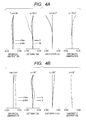
FIG. 3 is a lens sectional view of a zoom lens ofEmbodiment 2 at the wide angle end. -
FIG. 4A is a longitudinal aberration diagram of the zoom lens ofEmbodiment 2 at the wide angle end. -
FIG. 4B is a longitudinal aberration diagram of the zoom lens ofEmbodiment 2 at the telephoto end. -
FIG. 5 is a lens sectional view of a zoom lens ofEmbodiment 3 at the wide angle end. -
FIG. 6A is a longitudinal aberration diagram of the zoom lens ofEmbodiment 3 at the wide angle end. -
FIG. 6B is a longitudinal aberration diagram of the zoom lens ofEmbodiment 3 at the telephoto end. -
FIG. 7 is a lens sectional view of a zoom lens of Embodiment 4 at the wide angle end. -
FIG. 8A is a longitudinal aberration diagram of the zoom lens of Embodiment 4 at the wide angle end. -
FIG. 8B is a longitudinal aberration diagram of the zoom lens of Embodiment 4 at the telephoto end. -
FIG. 9 is a schematic diagram of principal parts of an image pickup device of the present invention. - Preferred embodiments of the present invention will now be described in detail in accordance with the accompanying drawings.
- A zoom lens of the present invention includes, in order from an object side to an image side: a first lens unit having a negative refractive power; a second lens unit having a positive refractive power; a middle lens group including at least one lens unit; and a final lens unit having a positive refractive power.
- The middle lens group includes a focus lens unit that has a negative refractive power and moves toward the image during focusing from infinity to a short distance. The intervals between adjacent lens units vary during at least one of zooming and focusing. An aperture stop is arranged on an object side of the focus lens unit. The focus lens unit is made up of one negative lens. The final lens unit has at least one aspheric surface.
-
FIGS. 1 ,3 ,5 and7 are lens sectional views of zoom lenses according to respective Embodiments 1 to 4 of the present invention at a wide angle end.FIGS. 2A, 2B ,4A, 4B ,6A, 6B ,8A and 8B are longitudinal aberration diagrams of the zoom lenses according to respective Embodiments 1 to 4 of the present invention. In these aberration diagrams, A and B are longitudinal aberration diagrams during focusing infinity at a wide angle end (short focal length end) and a telephoto end (long focal length end), respectively. -
FIG. 9 is a schematic diagram of principal parts of a camera (image pickup device) including a zoom lens of the present invention. The zoom lens of each embodiment is an imaging lens system adopted in an image pickup device, such as a video camera, a digital camera or a silver halide film camera. - In the lens sectional views, the left is an object side (front), and the right is an image side (rear). The lens sectional views illustrate a zoom lens OL. Li denotes an i-th lens unit, where i denotes an order from an object side. The diagrams illustrate a focus lens unit Lf, and a final lens unit Limg arranged nearest to the image. The diagrams also illustrate an aperture stop SP. A middle lens group LM includes at least one lens unit.
- An image plane IP corresponds to an image pickup plane of an image pickup element (photo-electric conversion element), such as a CCD sensor or a CMOS sensor, in the case where a zoom lens is adopted as an imaging optical system of any of a digital camera, a video camera and a monitoring camera. The image plane IP corresponds to a film surface in the case where a zoom lens is adopted as an imaging optical system of a silver halide film camera. The diagrams illustrate an optical axis OA. In the following embodiments, a wide angle end and a telephoto end indicate zoom positions at the respective ends of a range in which a lens unit for varying magnification can mechanically move on the optical axis. In the lens sectional views, arrows indicate movement loci of the respective lens units during zooming from a wide angle end to a telephoto end.
- Arrows pertaining to focusing indicate movement directions of lens units during focusing from infinity to a short distance. In spherical aberration diagrams, solid lines indicate d-lines (587.6 nm), and broken lines indicate g-lines (435.8 nm). In a diagram illustrating astigmatism, a solid line S indicates the sagittal direction of the d-line, and a broken line M indicates the meridional direction of the d-line. A diagram illustrating distortion illustrates distortion for the d-line. The diagram illustrates F-number Fno, and the half angle of view ω (degrees) for the imaging angle of view.
- The zoom lens OL of each embodiment includes, in order from an object side to an image side: a first lens unit L1 having a negative refractive power; a second lens unit L2 having a positive refractive power; a middle lens group LM including at least one lens unit; and a final lens unit Limg having a positive refractive power. The middle lens group LM includes a focus lens unit Lf that has a negative refractive power and moves toward an image during focusing from infinity to a short distance. An aperture stop SP is arranged on an object side of the focus lens unit Lf. The intervals between adjacent lens units vary during at least one of zooming and focusing.
- Here, a lens unit represents a subsystem separated by intervals that are along the optical axis and vary during at least one of zooming and focusing.
- In the zoom lens of the present invention, the focus lens unit Lf is arranged near the final lens unit Limg through which a light beam passes at a low height, thereby achieving reduction in size of the focus lens unit Lf and facilitating high speed focusing. Furthermore, in addition to reduction in the amount of focus driving and appropriate arrangement of refractive powers, variation in image magnification (imaging magnification) during focusing is suppressed. It is defined that the focal length fimg is of the final lens unit Limg, the focal length ff is of the focus lens unit Lf, and the focal length fw is of the entire system at the wide angle end. In this case, the following conditional expressions are satisfied.


- Next, the technical meaning of the conditional expressions (1) and (2) are described. The conditional expression (1) represents normalization acquired by dividing the focal length of the final lens unit Limg arranged nearest to the image by the focal length of the entire system at the wide angle end. If the lower limit of the conditional expression (1) is fallen short, the focal length of the final lens unit Limg is short, that is, the positive refractive power is strong. In this case, a back focus of a prescribed length is easily secured in the entire zoom lens. However, the refractive power of the lens unit on an object side having the negative refractive power is required to be strengthened accordingly.
- This case tends to represent the characteristics of a retrofocus type optical arrangement. Various aberrations including spherical aberration, coma, field curvature, and distortion increase. In particular, field curvature increases and is difficult to be corrected. Increase in back focus unfavorably increases the lens total length of the zoom lens accordingly.
- In contrast, if the upper limit of the conditional expression (1) is exceeded, the focal length of the final lens unit Limg is long, that is, the positive refractive power is low. Accordingly, the back focus is too short, which makes it difficult to arrange an image pickup element and a filter on the image side. Furthermore, as the back focus becomes short, the light beam incident angle on the image plane increases. When the light beam incident angle on the image plane is large, a light flux, which is to reach peripheral portions of the imaging range, is less likely to reach the light receiving element due to an effect from a microlens array arranged immediately before each light receiving element provided on the image plane. Accordingly, much shading occurs.
- The conditional expression (2) represents normalization acquired by dividing the focal length ff of the focus lens unit Lf by the focal length of the entire system at the wide angle end. If the lower limit of the conditional expression (2) is fallen short, the absolute value of the focal length of the focus lens unit Lf is large, and the negative refractive power is low. In this case, focus sensitivity of the focus lens unit Lf is low, and the amount of movement during focusing is large. Accordingly, high speed focusing is difficult. Furthermore, a space accommodating the amount of movement of the focus lens unit Lf is required to be secured in the zoom lens. This requirement increases the size of the entire system.
- In contrast, if the upper limit of the conditional expression (2) is exceeded, the absolute value of the focal length of the focus lens unit Lf is small, and the negative refractive power is too strong. In this case, variation in various aberrations associated with focusing increases, making it difficult to correct the various aberrations.
- In each embodiment, the conditional expressions (1) and (2) are satisfied. Accordingly, the various aberrations are favorably corrected while the size of the entire system is kept small. Furthermore, the back focus is sufficiently secured, and the amount of driving (the amount of movement) of the focus lens unit is reduced. Accordingly, variation in aberrations during focusing is reduced. Furthermore, the numerical ranges of the conditional expressions (1) and (2) are favorably set as follows.


- Moreover, in the zoom lens of the present invention, at least one of the following conditional expressions is favorably satisfied. It is defined that a transverse magnification βf is of the focus lens unit Lf at the wide angle end, a transverse magnification βfimg is of the subsystem from the focus lens unit Lf to the final lens unit Limg at the wide angle end, a back focus BFw is at the wide angle end, and an amount of movement mimg is of the final lens unit Limg during zooming from the wide angle end to the telephoto end.
- Here, the amount of movement during zooming from the wide angle end and to the telephoto end is the difference between positions of the lens unit at the wide angle end on the optical axis and the lens unit at the telephoto end on the optical axis. The sign of the amount of movement is positive when the lens unit is disposed nearer to the image at the telephoto end than at the wide angle end; the sign is negative when the lens unit is disposed nearer to the object at the telephoto end than at the wide angle end. Here, at least one of the following conditional expressions is favorably satisfied.


- Next, the technical meaning of each of the foregoing conditional expressions is described.
- The conditional expression (3) pertains to the ratio between the focal length of the final lens unit Limg disposed nearest to the image and the focal length of the focus lens unit Lf. If the lower limit of the conditional expression (3) is fallen short, that is, the focal length of the final lens unit Limg is relatively smaller than the absolute value of the focal length of the focus lens unit Lf, the positive refractive power of the final lens unit Limg is strong. This case tends to represent the characteristics of a retrofocus type optical arrangement with respect to the entire zoom lens. Much various aberrations occur. In particular, the field curvature increases, and becomes difficult to be corrected.
- Moreover, the absolute value of the focal length of the focus lens unit Lf is large. The negative refractive power of the focus lens unit Li is weak. The amount of driving during focusing is large. These characteristics are unfavorable. In contrast, if the focal length of the final lens unit Limg is long, exceeding the upper limit of the conditional expression (3), and the positive refractive power is weak, it is difficult to secure a back focus of a prescribed length. Moreover, if the absolute value of the focal length of the focus lens unit Lf is small and the negative refractive power is strong, variation in aberration during focusing is large.
- The conditional expression (4) pertains to focus sensitivity. The focus sensitivity is the ratio of amounts of movement for focusing in the case where the focus lens unit Lf moves in the optical axis direction by a unit amount. If the focus sensitivity is less than the lower limit of the conditional expression (4), the amount of movement of the focus lens unit Lf during focusing is large, which makes high speed focusing difficult. In contrast, if the focus sensitivity is too high, exceeding the upper limit of the conditional expression (4), the amount of movement of the focus lens unit Lf during focusing is small. Accordingly, drive control of the focus lens unit Lf during focusing becomes difficult.
- The conditional expression (5) represents normalization acquired by dividing the back focus BFw at the wide angle end by the focal length of the entire system at the wide angle end. If the lower limit of the conditional expression (5) is fallen short, the back focus is too short. Accordingly, arrangement of the image pickup element and the filter on the image side is difficult. The light beam incident angle on the image plane increases, and a light flux that is to reach the peripheral portions of the imaging range and actually reaches the light receiving element decreases, thereby causing much shading. In contrast, if the upper limit of the conditional expression (5) is exceeded, the back focus is long, increasing the size of the entire zoom lens.
- The conditional expression (6) represents normalization acquired by dividing the amount of movement mimg of the final lens unit Limg during zooming from the wide angle end to the telephoto end by the focal length of the entire system at the wide angle end. If the lower limit of the conditional expression (6) is fallen short, the amount of movement of the final lens unit Limg during zooming from the wide angle end to the telephoto end decreases. Accordingly, it is difficult to achieve a high zoom ratio. In contrast, the upper limit of the conditional expression (6) is exceeded, the amount of movement of the final lens unit Limg during zooming from the wide angle end to the telephoto end is too large, increasing the size of the zoom lens. Furthermore, the numerical ranges of the conditional expressions (3) to (6) are favorably configured as follows.


- In each embodiment, the focus lens unit Lf favorably is made up of one lens. High speed focusing requires the weight of the focus lens unit Lf to be light as much as possible. Thus, the focus lens unit Lf favorably is made up of one lens.
- Further, in each embodiment, the first lens unit L1 having a negative refractive power comprises a first lens having a negative refractive power and a plastic aspheric lens having a negative refractive power in order from an object side to an image side, and satisfies at least one of the following conditional expressions:


- The conditional expression (8) relates to the distance between the first lens having a negative refractive power and the plastic aspheric lens having a negative refractive power along the optical axis. If the distance between the first lens having a negative refractive power and the plastic aspheric lens having a negative refractive power along the optical axis decreases to make the lower limit of the conditional expression (8) fallen short, interference is likely to occur between the first lens and the plastic aspheric lens. Accordingly, it is not preferable since a scratch or the like is likely to be generated on the first lens and the plastic aspheric lens. In contrast, if the distance between the first lens having a negative refractive power and the plastic aspheric lens having a negative refractive power along the optical axis increases to make the upper limit of the conditional expression (8) exceeded, an incident height of an off-axial chief ray to the plastic aspheric lens decreases, an aspheric surface effect decreases. Accordingly, it is difficult to correct a distortion and a field curvature.
- Furthermore, the numerical ranges of the conditional expressions (7) and (8) are favorably configured as follows.


- In each embodiment, the final lens unit Limg favorably has at least one aspheric surface. Arrangement of the aspheric surface on the final lens unit Limg facilitates correcting various aberrations that tend to occur in a retrofocus type optical arrangement, particularly field curvature. Next, the lens configurations of the zoom lenses in the respective embodiments are described.
- Hereinafter, referring to
FIG. 1 , a lens configuration of a zoom lens OL of Embodiment 1 of the present invention is described. The zoom lens OL of Embodiment 1 includes, in order from the object side to the image side: a first lens unit L1 having a negative refractive power; a second lens unit L2 having a positive refractive power; a third lens unit L3 having a negative refractive power; and a fourth lens unit L4 having a positive refractive power. The lens units move along respective loci different from each other as indicated by arrows during zooming. During zooming from the wide angle end to the telephoto end, the first lens unit L1 moves along a locus convex toward the image. The second lens unit L2, the third lens unit L3 and the fourth lens unit L4 move toward the object. - Embodiment 1 is a zoom lens with a wide angle of view where the zoom ratio is 1.70 and the imaging angle of view (2ω) ranges from 105.84° to 75.96°. In Embodiment 1, the fourth lens unit L4 is a final lens unit (Limg). The third lens unit L3 is a focus lens unit (Lf) that moves along the optical axis toward the image during focusing from infinity to a short distance.
- As illustrated in
FIGS. 2A and 2B , in the zoom lens of this embodiment, various aberrations including spherical aberration, coma, field curvature, and distortion are favorably corrected. Furthermore, the position in the optical axis direction and appropriate refractive power arrangement of the third lens unit L3 suppress variation in image magnification during focusing. As a result, the variation in image magnification during focusing is small, and the third lens unit L3 is small and lightweight, thereby facilitating high speed focusing. - Hereinafter, referring to
FIG. 3 , a lens configuration of a zoom lens OL ofEmbodiment 2 of the present invention is described. The refractive power arrangement of the lens units in the zoom lens OL inEmbodiment 2 is identical to the arrangement in Embodiment 1. During zooming from the wide angle end to the telephoto end, the first lens unit L1 moves along a locus convex toward the image. The second lens unit L2, the third lens unit L3 and the fourth lens unit L4 move along the same locus toward the object.Embodiment 2 is a zoom lens with a wide angle of view where the zoom ratio is 1.54 and the imaging angle of view ranges from 100.68° to 75.96°. - As illustrated in
FIGS. 4A and 4B , in the zoom lens of this embodiment, various aberrations including spherical aberration, coma, field curvature, and distortion are favorably corrected. Furthermore, the position in the optical axis direction and appropriate refractive power arrangement of the third lens unit L3 suppress variation in image magnification during focusing. As a result, the variation in image magnification during focusing is small, and the third lens unit L3 is small and lightweight, thereby facilitating high speed focusing. - Hereinafter, referring to
FIG. 5 , a lens configuration of a zoom lens OL ofEmbodiment 3 of the present invention is described. The zoom lens OL ofEmbodiment 3 includes, in order from the object side to the image side: a first lens unit L1 having a negative refractive power; a second lens unit L2 having a positive refractive power; a third lens unit L3 having a positive refractive power; a fourth lens unit L4 having a negative refractive power; and a fifth lens unit L5 having a positive refractive power. During zooming from the wide angle end to the telephoto end, the first lens unit L1 moves along a locus convex toward the image. The second lens unit L2 to the fifth lens unit L5 move toward the object along respective loci different from each other. - In various pieces of data of after-mentioned Numerical Example 3, the interval d15 between the second lens unit L2 and the third lens unit L3 is represented to have the same value of 3.21 at the wide angle end, an intermediate position, and the telephoto end. This representation is caused by rounding off from the second decimal place. Actual values are 3.2083 at the wide angle end, 3.2082 at the intermediate position, and 3.2081 at the telephoto end. The interval d15 between the second lens unit L2 and the third lens unit L3 varies during zooming even though the variation is slight.
-
Embodiment 3 is a zoom lens with a wide angle of view where the zoom ratio is 2.24 and the imaging angle of view ranges from 110.24° to 65.2°. InEmbodiment 3, the fifth lens unit L5 is a final lens unit (Limg). The fourth lens unit L4 is a focus lens unit (Lf) that moves along the optical axis toward the image during focusing from infinity to a short distance. - As illustrated in
FIGS. 6A and 6B , in the zoom lens of this embodiment, various aberrations including spherical aberration, coma, field curvature, and distortion are favorably corrected. Furthermore, the position in the optical axis direction and appropriate refractive power arrangement of the fourth lens unit L4 suppress variation in image magnification during focusing. As a result, the variation in image magnification during focusing is small. The fourth lens unit L4 is small and lightweight, thereby facilitating high speed focusing. - Hereinafter, referring to
FIG. 7 , a lens configuration of a zoom lens OL of Embodiment 4 of the present invention is described. The zoom lens OL of Embodiment 4 includes, in order from the object side to the image side: a first lens unit L1 having a negative refractive power; a second lens unit L2 having a positive refractive power; a third lens unit L3 having a negative refractive power; a fourth lens unit L4 having a negative refractive power; and a fifth lens unit L5 having a positive refractive power. During zooming from the wide angle end to the telephoto end, the first lens unit L1 moves along a locus convex toward the image. The second lens unit L2 to the fifth lens unit L5 move toward the object along respective loci different from each other. Embodiment 4 is a zoom lens with a wide angle of view where the zoom ratio is 1.44 and the imaging angle of view ranges from 94.22° to 73.52°. - In Embodiment 4, the fifth lens unit L5 is a final lens unit (Limg). The third lens unit L3 is a focus lens unit (Lf) that moves along the optical axis toward the image during focusing from infinity to a short distance.
- As illustrated in
FIGS. 8A and 8B , in the zoom lens of this embodiment, various aberrations including spherical aberration, coma, field curvature, and distortion are favorably corrected. Furthermore, the position in the optical axis direction and appropriate refractive power arrangement of the third lens unit L3 suppress variation in image magnification during focusing. As a result, the variation in image magnification during focusing is small, and the third lens unit L3 is small and lightweight, thereby facilitating high speed focusing. -
FIG. 9 is a schematic diagram of principal parts of a single-lens reflex camera. InFIG. 9 , an imagingoptical system 10 includes a zoom lens 1 of any of Embodiments 1 to 4. The imaging optical system 1 is held by alens barrel 2, which serves as a holding member. The diagram also illustrates acamera body 20. Thecamera body 20 includes aquick return mirror 3, a focusing glass 4, apentagonal Dach prism 5 and aneyepiece 6. Thequick return mirror 3 reflects a light flux from the imagingoptical system 10 upward. The focusing glass 4 is arranged on an image formation position of the imagingoptical system 10. Thepentagonal Dach prism 5 converts a reverse image formed on the focusing glass 4 into an erect image. An observer observes the erect image through theeyepiece 6. - On a
photosensitive surface 7, a solid image pickup element (photo-electric conversion element), such as a CCD sensor or a CMOS sensor, which receives light of an image, or a silver halide film is arranged. During imaging, thequick return mirror 3 is retracted from the optical path, and an image is formed on thephotosensitive surface 7 by the imagingoptical system 10. - Thus, the zoom lens of the present invention is applied to an image pickup device, such as an interchangeable lens for a single-lens reflex camera, thereby achieving an image pickup device having a high optical performance. Furthermore, the zoom lens of the present invention is applicable to a single-lens reflex camera having a mirror lens with no quick return mirror in an analogous manner. The zoom lens of the present invention is applicable not only to a digital camera, a video camera and a silver halide film camera but also to optical devices, such as a telescope, a binocular, a copier and a projector. The favorable embodiments of the present invention have been described above. However, the present invention is not limited to these embodiments. Instead, various modifications and changes can be made within the scope of the gist thereof.
- Specific numerical data of zoom lenses of Numerical Examples 1 to 4 are hereinafter described. The order i is counted from the object. The surface number i is sequentially counted from the object side. The curvature radius ri (mm) and the interval di (mm) are between the i-th surface and the (i + 1) -th surface. A refractive index ndi and an Abbe number νdi are between the i-th surface and the (i + 1)-th surface for d-line. A back focus BF is also represented. The lens total length is a distance from the first lens surface to the image plane.
- An aspheric surface is represented by adding a symbol * after the surface number. It is defined that x denotes a displacement from a surface apex in the optical axis direction, h denotes a height from the optical axis in a direction perpendicular to the optical axis, r denotes a paraxial curvature radius, K denotes a conic constant, and B, C, D, E and F ... denote aspheric surface coefficients of respective degrees; an aspheric surface shape is represented as follows.

- Note that "e ± XX" of each aspheric surface coefficient means "×10±xx". Table 1 illustrates numeric values corresponding to the conditional expressions described above.
(Numerical Example 1) Unit mm Surface Data Surface number r d nd vd Effective diameter 1 65.393 2.00 1.77250 49.6 41.98 2 19.774 0.21 31.81 3 19.623 2.20 1.52996 55.8 31.64 4* 12.890 14.82 29.14 5 26.261 0.90 1.77250 49.6 18.33 6 11.536 5.58 15.90 7 -18.464 0.80 1.59522 67.7 15.61 8 344.979 0.10 15.85 9 41.566 3.39 1.72047 34.7 15.99 10 -30.947 (Variable) 15.90 11 -46.472 1.11 1.48749 70.2 8.55 12 -29.312 1.23 8.73 13 23.761 0.80 1.91082 35.3 8.95 14 9.192 3.37 1.60342 38.0 8.77 15 -53.118 2.19 8.89 16(Stop) ∞ 2.96 8.88 17 -115.956 0.80 1.83481 42.7 8.96 18 9.582 3.45 1.64769 33.8 9.10 19 -187.956 0.15 9.76 20 16.818 4.37 1.49700 81.5 10.68 21 -14.618 (Variable) 11.33 22 -51.594 0.70 1.91082 35.3 11.34 23 59.318 (Variable) 11.48 24 192.633 0.80 1.91082 35.3 13.31 25 14.245 5.88 1.58313 59.4 13.73 26* -19.863 (Variable) 15.00 Image plane ∞ - Aspheric surface data
- Fourth Surface
- K =-4.75949e-001 B=-3.82851e-005 C=-7.50548e-008 D=-2.94600e-010
- E= 1.45343e-012 F=-5.04519e-015
- Twenty Sixth Surface
- K = 0.00000e+000 B= 2.17541e-005 C=-2.27082e-007 D= 1.49496e-008
- E=-2.85254e-010 F= 2.16561e-012
- Various Pieces of Data
Zoom Ratio 1.70 Wide-angle Intermediate Telephoto Focal length 10.30 13.78 17.46 F-number 4.64 5.18 5.80 Half angle of view (degree) 52.92 44.69 37.98 Image height 13.63 13.63 13.63 Total lens length 116.58 113.53 114.08 BF 35.35 42.10 48.84 d10 17.35 7.56 1.37 d21 1.20 1.57 2.05 d23 4.85 4.48 4.00 d26 35.35 42.10 48.84 Entrance pupil position 16.70 16.08 15.54 Exit pupil position -29.55 -29.11 -28.54 Front principal point position 25.36 27.19 29.07 Rear principal point position 25.05 28.32 31.38 Zoom Lens Unit Data Unit Start surface Focal length Lens configuration length Front principal point position Rear principal point position 1 1 -13.17 30.01 6.53 -20.04 2 11 18.76 20.43 13.34 -4.68 3 22 -30.20 0.70 0.17 -0.20 4 24 76.60 6.68 8.63 5.03 Single Lens Data Lens Start surface Focal length 1 1 -37.41 2 3 -79.94 3 5 -27.36 4 7 -29.42 5 9 25.11 6 11 159.44 7 13 -16.90 8 14 13.26 9 17 -10.57 10 18 14.17 11 20 16.50 12 22 -30.20 13 24 -16.92 14 25 15.19 (Numerical Example 2) Unit mm Surface Data Surface number r d nd vd Effective diameter 1 67.024 2.00 1.51633 64.1 43.22 2 19.596 0.07 32.10 3 19.534 2.20 1.52996 55.8 32.02 4* 12.851 15.00 28.71 5 36.072 0.90 1.83481 42.7 17.55 6 10.799 5.36 14.90 7 -18.784 0.80 1.59522 67.7 14.63 8 -77.361 0.15 14.89 9 30.490 3.06 1.72047 34.7 15.03 10 -43.008 (Variable) 14.80 11 -46.868 1.05 1.48749 70.2 8.17 12 -28.621 1.55 8.33 13 22.743 0.80 1.83481 42.7 8.58 14 9.162 3.16 1.54814 45.8 8.42 15 -29.837 2.05 8.52 16(Stop) ∞ 3.38 8.34 17 -16.362 0.80 1.91082 35.3 8.13 18 15.294 2.91 1.72151 29.2 8.63 19 -21.362 0.19 9.80 20 22.594 3.25 1.49700 81.5 11.00 21 -15.930 1.30 11.50 22 84.915 0.80 1.91082 35.3 11.82 23 29.661 3.57 11.82 24 146.421 0.90 1.91082 35.3 13.01 25 12.713 6.08 1.58313 59.4 13.41 26* -21.551 (Variable) 14.80 Image plane ∞ - Aspheric surface data
- Fourth Surface
- K =-4.75949e-001 B=-2.14159e-005 C=-6.60610e-008 D=-2.73069e-010
- E= 1.03120e-012 F=-4.58549e-015
- Twenty Sixth Surface
- K = 0.00000e+000 B= 6.77849e-006 C=-2.38100e-007 D= 6.64682e-009
- E=-1.14977e-010 F= 6.72515e-013
- Various Pieces of Data
Zoom Ratio 1.54 Wide-angle Intermediate Telephoto Focal length 11.30 15.06 17.46 F-number 4.64 5.28 5.69 Half angle of view (degree) 50.34 42.15 37.98 Image height 13.63 13.63 13.63 Total lens length 110.71 108.93 109.83 BF 35.00 42.24 46.86 d10 14.37 5.35 1.62 d26 35.00 42.24 46.86 Entrance pupil position 18.33 17.60 17.21 Exit pupil position -26.53 -26.53 -26.53 Front principal point position 27.55 29.36 30.52 Rear principal point position 23.70 27.18 29.41 Zoom Lens Unit Data Unit Start surface Focal length Lens configuration length Front principal point position Rear principal point position 1 1 -14.56 29.54 7.56 -19.70 2 11 21.10 19.15 13.10 -4.60 3 22 -50.40 0.80 0.65 0.23 4 24 105.00 6.98 11.11 7.55 Single Lens Data Lens Start surface Focal length 1 1 -54.42 2 3 -80.01 3 5 -18.77 4 7 -41.89 5 9 25.20 6 11 148.02 7 13 -18.89 8 14 13.17 9 17 -8.58 10 18 12.78 11 20 19.34 12 22 -50.40 13 24 -15.33 14 25 14.67 (Numerical Example 3) Unit mm Surface Data Surface number r d nd vd Effective diameter 1* 62.304 1.70 1.80400 46.6 45.07 2 19.433 0.20 33.92 3 19.433 2.30 1.52996 55.8 33.80 4* 12.025 11.34 28.20 5 25.935 0.90 1.77250 49.6 23.19 6 12.880 8.02 19.82 7 -19.426 0.80 1.59522 67.7 19.44 8 -85.193 0.15 19.86 9 56.600 3.28 1.72047 34.7 20.01 10 -49.434 (Variable) 19.87 11 -211.721 1.73 1.48749 70.2 9.88 12 -29.805 1.07 10.15 13 22.774 0.70 1.91082 35.3 10.44 14 9.661 3.64 1.58144 40.8 10.20 15 -58.601 (Variable) 10.34 16(Stop) ∞ 3.19 10.38 17 -27.572 0.70 1.83481 42.7 10.40 18 11.105 3.57 1.71736 29.5 10.87 19 -31.515 0.15 11.32 20 21.783 3.76 1.49700 81.5 11.63 21 -17.267 (Variable) 11.55 22 -45.767 0.60 1.91082 35.3 10.46 23 49.785 (Variable) 10.32 24 105.075 0.70 1.91082 35.3 10.31 25 12.506 5.05 1.49710 81.6 10.67 26* -14.235 (Variable) 12.13 Image plane ∞ - Aspheric surface data
- First surface
- K =-3.81397e+000 B= 1.78033e-005 C=-6.05780e-009 D=-5.40009e-011
- E = 8.31988e-014 F=-1.64860e-017
- Fourth Surface
- K =-3.72017e-001 B=-1.05015e-005 C= 3.69314e-008 D= 1.44990e-009
- E =-1.71363e-011 F= 2.40573e-014
- Twenty sixth surface
- K = 0.00000e+000 B=-1.23310e-005 C=-4.96373e-007 D= 1.19352e-008
- E =-5.80436e-010 F= 5.32465e-012
- Various Pieces of Data
Zoom Ratio 2.24 Wide-angle Intermediate Telephoto Focal length 9.50 15.20 21.31 F-number 4.40 5.08 5.80 Half angle of view (degree) 55.12 41.88 32.60 Image height 13.63 13.63 13.63 Total lens length 123.37 117.73 120.93 BF 37.30 48.94 60.58 d10 26.64 9.54 1.29 d15 3.21 3.21 3.21 d21 0.50 1.07 1.74 d23 2.20 1.43 0.58 d26 37.30 48.94 60.58 Entrance pupil position 16.04 15.23 14.60 Exit pupil position -22.20 -21.22 -20.15 Front principal point position 24.03 27.13 30.29 Rear principal point position 27.80 33.74 39.27 Zoom Lens Unit Data Unit Start surface Focal length Lens configuration length Front principal point position Rear principal point position 1 1 -13.24 28.68 5.32 -20.37 2 11 33.64 7.13 2.30 -2.67 3 16 24.97 11.37 9.46 1.91 4 22 -26.10 0.60 0.15 -0.16 5 24 74.82 5.75 8.97 5.89 Single Lens Data Lens Start surface Focal length 1 1 -35.76 2 3 -66.69 3 5 -34.15 4 7 -42.47 5 9 37.11 6 11 70.94 7 13 -18.90 8 14 14.55 9 17 -9.41 10 18 11.86 11 20 20.02 12 22 -26.10 13 24 -15.64 14 25 14.29 (Numerical Example 4) Unit mm Surface Data Surface number r d nd vd Effective diameter 1 41.995 2.00 1.48749 70.2 40.77 2 20.525 0.20 32.47 3 20.525 2.20 1.52996 55.8 32.32 4* 13.319 15.44 27.96 5 -431.645 0.90 1.80400 46.6 17.10 6 12.788 4.23 14.82 7 -27.672 0.80 1.43875 94.9 14.69 8 -50.804 0.15 14.76 9 25.460 3.01 1.80000 29.8 14.69 10 -7092.378 (Variable) 14.14 11 -58.261 1.43 1.48749 70.2 8.75 12 -29.878 1.44 8.48 13 25.253 0.80 1.91082 35.3 8.27 14 10.706 3.96 1.59551 39.2 8.14 15 -34.577 2.22 8.26 16(Stop) ∞ 2.13 8.07 17 -24.628 0.80 1.83481 42.7 7.93 18 15.303 3.44 1.65844 50.9 8.75 19 -25.557 0.19 10.11 20 27.141 4.62 1.49700 81.5 11.03 21 -17.792 (Variable) 11.97 22 -38.831 0.60 1.65160 58.5 12.15 23 79.759 (Variable) 12.41 24 -121.211 1.20 1.52996 55.8 14.62 25* 378.042 (Variable) 15.03 26 113.565 0.80 1.91082 35.3 15.38 27 23.771 4.30 1.55332 71.7 15.58 28* -22.352 (Variable) 16.16 Image plane ∞ - Aspheric surface data
- Fourth Surface
- K =-4.75949e-001 B=-6.29028e-006 C=-3.11309e-008 D=-1.05016e-010
- E = 5.20437e-014 F=-3.03565e-015
- Twenty Fifth Surface
- K =-4.75949e-001 B=-3.82214e-005 C=-5.08157e-007 D=-7.83186e-009
- E = 1.22990e-010 F=-7.47246e-013
- Twenty Eighth Surface
- K = 0.00000e+000 B= 5.68874e-005 C= 1.23900e-007 D= 1.40620e-008
- E =-1.42260e-010 F= 7.39419e-013
- Various Pieces of Data
Zoom Ratio 1.44 Wide-angle Intermediate Telephoto Focal length 12.66 16.37 18.24 F-number 4.64 5.16 5.44 Half angle of view (degree) 47.11 39.79 36.76 Image height 13.63 13.63 13.63 Total lens length 107.45 105.01 105.13 BF 30.88 36.91 40.32 d10 12.55 4.68 1.96 d21 1.00 1.46 1.51 d23 5.56 4.55 3.94 d25 0.60 0.57 0.53 d28 30.88 36.91 40.32 Entrance pupil position 20.48 19.67 19.33 Exit pupil position -29.60 -28.02 -26.82 Front principal point position 30.49 31.92 32.61 Rear principal point position 18.22 20.54 22.08 Zoom Lens Unit Data Unit Start surface Focal length Lens configuration length Front principal point position Rear principal point position 1 1 -15.52 28.93 9.55 -16.25 2 11 19.75 21.03 12.87 -5.63 3 22 -40.00 0.60 0.12 -0.24 4 24 -173.04 1.20 0.19 -0.59 5 26 55.00 5.10 4.02 0.88 Single Lens Data Lens Start surface Focal length 1 1 -84.95 2 3 -80.05 3 5 -15.43 4 7 -140.00 5 9 31.72 6 11 123.76 7 13 -20.95 8 14 14.19 9 17 -11.20 10 18 15.04 11 20 22.39 12 22 -40.00 13 24 -173.04 14 26 -33.15 15 27 21.54 Table 1 Conditional Expression Embodiment 1 Embodiment 2 Embodiment 3 Embodiment 4 (1) 7.44 9.29 7.88 4.34 (2) -2.93 -4.46 -2.75 -3.16 (3) 2.54 2.08 2.87 1.37 (4) 3.18 1.69 3.81 1.98 (5) 3.43 3.1 3.93 2.44 (6) 1.31 1.05 2.45 0.75 (7) -7.76 -7.08 -7.02 -6.32 (8) 0.0018 0.0006 0.0016 0.0019 - While the present invention has been described with reference to exemplary embodiments, it is to be understood that the invention is not limited to the disclosed exemplary embodiments. The scope of the following claims is to be accorded the broadest interpretation so as to encompass all such modifications and equivalent structures and functions.
- A zoom lens includes, in order from an object side to an image side: first and second lens units having negative and positive refractive powers, respectively; a middle lens group; and a final lens unit having a positive refractive power, wherein the middle lens group comprises a focus lens unit that has a negative refractive power and moves toward the image side during focusing from infinity to a short distance, the intervals between adjacent lens units vary during at least one of zooming and focusing, and wherein the focal length fimg of the final lens unit, the focal length ff of the focus lens unit, and the focal length fw of the entire system at the wide angle end are appropriately configured.
Claims (13)
- A zoom lens, comprising, in order from an object side to an image side: a first lens unit having a negative refractive power; a second lens unit having a positive refractive power; a middle lens group including at least one lens unit; and a final lens unit having a positive refractive power, wherein the middle lens group comprises a focus lens unit that has a negative refractive power and moves toward the image side during focusing from infinity to a short distance, intervals between adjacent lens units vary during at least one of zooming and focusing, and wherein conditional expressions

and
are satisfied where a focal length of the final lens unit is fimg, a focal length of the focus lens unit is ff, and a focal length of an entire system at a wide angle end is fw. - The zoom lens according to claim 1,
wherein a conditional expression
is satisfied. - The zoom lens according to claims 1 or 2,
wherein a conditional expression
- The zoom lens according to any one of claims 1 to 3,
wherein a conditional expression
is satisfied where a back focus at the wide angle end is BFw. - The zoom lens according to any one of claims 1 to 4,
wherein a conditional expression
is satisfied where an amount of movement of the final lens unit during zooming from the wide angle end to a telephoto end is mimg. - The zoom lens according to any one of claims 1 to 5, wherein the focus lens unit is made up of one negative lens.
- The zoom lens according to any one of claims 1 to 6, wherein the final lens unit has at least one aspheric surface.
- The zoom lens according to any one of claims 1 to 7, wherein the zoom lens comprises, in order from the object side to the image side: a first lens unit having a negative refractive power; a second lens unit having a positive refractive power; a third lens unit having a negative refractive power; and a fourth lens unit having a positive refractive power, and wherein the focus lens unit is the third lens unit, and the final lens unit is the fourth lens unit.
- The zoom lens according to any one of claims 1 to 7, wherein the zoom lens comprises, in order from the object side to the image side: a first lens unit having a negative refractive power; a second lens unit having a positive refractive power; a third lens unit having a positive refractive power; a fourth lens unit having a negative refractive power; and a fifth lens unit having a positive refractive power, and wherein the focus lens unit is the fourth lens unit, and the final lens unit is the fifth lens unit.
- The zoom lens according to any one of claims 1 to 7, wherein the zoom lens comprises, in order from the object side to the image side: a first lens unit having a negative refractive power; a second lens unit having a positive refractive power; a third lens unit having a negative refractive power; a fourth lens unit having a negative refractive power; and a fifth lens unit having a positive refractive power, and wherein the focus lens unit is the third lens unit, and the final lens unit is the fifth lens unit.
- The zoom lens according to any one of claims 1 to 10, wherein the first lens unit comprises a first lens having a negative refractive power and a plastic aspheric lens having a negative refractive power in order from an object side to an image side, and wherein a conditional expression

is satisfied where a focal length of the plastic aspheric lens is fasph. - The zoom lens according to any one of claims 1 to 11, wherein the first lens unit comprises a first lens having a negative refractive power and a plastic aspheric lens having a negative refractive power in order from an object side to an image side, and wherein a conditional expression

is satisfied where a distance between the first lens having a negative refractive power and the plastic aspheric lens having a negative refractive power along the optical axis is dasph and a distance from a lens surface of the first lens at an object side to an image plane along the optical axis is TL. - An image pickup device, comprising: the zoom lens according to any one of claims 1 to 12; and an image pickup element that takes an optical image formed by the zoom lens.
Applications Claiming Priority (2)
| Application Number | Priority Date | Filing Date | Title |
|---|---|---|---|
| JP2013092174 | 2013-04-25 | ||
| JP2014081262A JP6422231B2 (en) | 2013-04-25 | 2014-04-10 | Zoom lens and imaging apparatus having the same |
Publications (3)
| Publication Number | Publication Date |
|---|---|
| EP2796914A2 true EP2796914A2 (en) | 2014-10-29 |
| EP2796914A3 EP2796914A3 (en) | 2014-12-24 |
| EP2796914B1 EP2796914B1 (en) | 2019-08-14 |
Family
ID=50542914
Family Applications (1)
| Application Number | Title | Priority Date | Filing Date |
|---|---|---|---|
| EP14165818.7A Active EP2796914B1 (en) | 2013-04-25 | 2014-04-24 | Zoom lens and image pickup device including the same |
Country Status (4)
| Country | Link |
|---|---|
| US (1) | US9377606B2 (en) |
| EP (1) | EP2796914B1 (en) |
| JP (1) | JP6422231B2 (en) |
| CN (1) | CN104122660B (en) |
Cited By (1)
| Publication number | Priority date | Publication date | Assignee | Title |
|---|---|---|---|---|
| US10317654B2 (en) | 2014-12-26 | 2019-06-11 | Nikon Corporation | Variable magnification optical system, optical apparatus, and variable magnification optical system manufacturing method |
Families Citing this family (12)
| Publication number | Priority date | Publication date | Assignee | Title |
|---|---|---|---|---|
| JP6489634B2 (en) * | 2014-11-18 | 2019-03-27 | オリンパス株式会社 | Inner focus macro lens and imaging apparatus using the same |
| JP2016126282A (en) * | 2015-01-08 | 2016-07-11 | 株式会社タムロン | Wide-angle zoom lens and imaging apparatus |
| JP6478900B2 (en) | 2015-11-09 | 2019-03-06 | キヤノン株式会社 | Lens apparatus and imaging apparatus having the same |
| US10126536B2 (en) * | 2016-02-24 | 2018-11-13 | Canon Kabushiki Kaisha | Zoom lens and image pickup apparatus including the same |
| US10197778B2 (en) * | 2016-10-11 | 2019-02-05 | Canon Kabushiki Kaisha | Zoom lens and image pickup apparatus including the same |
| CN110520777B (en) * | 2017-04-05 | 2021-12-10 | 株式会社尼康 | Variable magnification optical system, optical device, and method of manufacturing variable magnification optical system |
| JP6946774B2 (en) * | 2017-06-21 | 2021-10-06 | 株式会社ニコン | Variable magnification optics and optics |
| JP6969780B2 (en) * | 2017-07-24 | 2021-11-24 | 株式会社シグマ | Large aperture ratio lens |
| JP6615160B2 (en) | 2017-08-07 | 2019-12-04 | キヤノン株式会社 | Optical system and imaging apparatus having the same |
| JP7009134B2 (en) | 2017-09-25 | 2022-01-25 | キヤノン株式会社 | Zoom lens and image pickup device with it |
| JP7086579B2 (en) | 2017-11-24 | 2022-06-20 | キヤノン株式会社 | Zoom lens and image pickup device |
| TW202204958A (en) * | 2020-07-24 | 2022-02-01 | 大陸商信泰光學(深圳)有限公司 | Image capturing device and zoom control method thereof |
Citations (4)
| Publication number | Priority date | Publication date | Assignee | Title |
|---|---|---|---|---|
| JPH07306362A (en) | 1994-05-13 | 1995-11-21 | Canon Inc | Zoom lens |
| JP2001343584A (en) | 2000-06-02 | 2001-12-14 | Konica Corp | Zoom lens |
| JP2006058584A (en) | 2004-08-19 | 2006-03-02 | Canon Inc | Zoom lens and imaging device incorporating it |
| US7777967B2 (en) | 2007-02-08 | 2010-08-17 | Ricoh Company, Ltd. | Zoom lens, camera device and personal digital assistant |
Family Cites Families (17)
| Publication number | Priority date | Publication date | Assignee | Title |
|---|---|---|---|---|
| US5059006A (en) | 1989-12-22 | 1991-10-22 | Ricoh Company Ltd. | Compact zoom lens |
| JP3363571B2 (en) * | 1994-03-30 | 2003-01-08 | キヤノン株式会社 | Rear focus zoom lens and imaging system |
| JP4067828B2 (en) | 2002-01-21 | 2008-03-26 | オリンパス株式会社 | Zoom lens and electronic imaging apparatus using the same |
| JP4844012B2 (en) | 2005-05-26 | 2011-12-21 | コニカミノルタオプト株式会社 | Variable magnification optical system and imaging apparatus |
| JP2006337647A (en) * | 2005-06-01 | 2006-12-14 | Canon Inc | Zoom lens |
| KR100745510B1 (en) | 2005-12-15 | 2007-08-02 | 삼성테크윈 주식회사 | Compact zoom lens |
| JP2009282465A (en) | 2008-05-26 | 2009-12-03 | Sony Corp | Zoom lens and imaging apparatus |
| JP2010061007A (en) | 2008-09-05 | 2010-03-18 | Sony Corp | Zoom lens and image capturing apparatus |
| JP2010160198A (en) | 2009-01-06 | 2010-07-22 | Sony Corp | Zoom lens and image capture apparatus |
| JP4845993B2 (en) * | 2009-04-22 | 2011-12-28 | キヤノン株式会社 | Zoom lens and optical apparatus having the same |
| JP5516127B2 (en) * | 2010-06-23 | 2014-06-11 | 株式会社ニコン | Zoom lens, imaging device, and zoom lens manufacturing method |
| JP2012027262A (en) | 2010-07-23 | 2012-02-09 | Olympus Imaging Corp | Zoom lens and imaging device having the same |
| CN103620470B (en) * | 2011-06-24 | 2015-12-09 | 富士胶片株式会社 | Zoom lens and imaging device |
| JP5769554B2 (en) * | 2011-08-31 | 2015-08-26 | オリンパス株式会社 | Standard lens |
| JP5975773B2 (en) | 2012-07-30 | 2016-08-23 | キヤノン株式会社 | Zoom lens and imaging apparatus having the same |
| JP6177549B2 (en) * | 2013-03-13 | 2017-08-09 | 株式会社タムロン | Super wide-angle zoom lens |
| JP6314471B2 (en) * | 2013-12-19 | 2018-04-25 | リコーイメージング株式会社 | Zoom lens system |
-
2014
- 2014-04-10 JP JP2014081262A patent/JP6422231B2/en active Active
- 2014-04-22 US US14/258,655 patent/US9377606B2/en active Active
- 2014-04-24 EP EP14165818.7A patent/EP2796914B1/en active Active
- 2014-04-25 CN CN201410169546.XA patent/CN104122660B/en active Active
Patent Citations (4)
| Publication number | Priority date | Publication date | Assignee | Title |
|---|---|---|---|---|
| JPH07306362A (en) | 1994-05-13 | 1995-11-21 | Canon Inc | Zoom lens |
| JP2001343584A (en) | 2000-06-02 | 2001-12-14 | Konica Corp | Zoom lens |
| JP2006058584A (en) | 2004-08-19 | 2006-03-02 | Canon Inc | Zoom lens and imaging device incorporating it |
| US7777967B2 (en) | 2007-02-08 | 2010-08-17 | Ricoh Company, Ltd. | Zoom lens, camera device and personal digital assistant |
Cited By (1)
| Publication number | Priority date | Publication date | Assignee | Title |
|---|---|---|---|---|
| US10317654B2 (en) | 2014-12-26 | 2019-06-11 | Nikon Corporation | Variable magnification optical system, optical apparatus, and variable magnification optical system manufacturing method |
Also Published As
| Publication number | Publication date |
|---|---|
| JP2014225002A (en) | 2014-12-04 |
| US20140320976A1 (en) | 2014-10-30 |
| US9377606B2 (en) | 2016-06-28 |
| CN104122660A (en) | 2014-10-29 |
| EP2796914A3 (en) | 2014-12-24 |
| JP6422231B2 (en) | 2018-11-14 |
| CN104122660B (en) | 2017-04-26 |
| EP2796914B1 (en) | 2019-08-14 |
Similar Documents
| Publication | Publication Date | Title |
|---|---|---|
| EP2796914B1 (en) | Zoom lens and image pickup device including the same | |
| US10222594B2 (en) | Zoom lens and image pickup apparatus including the same | |
| EP2942655B1 (en) | Optical system and image pickup apparatus including the same | |
| US9146388B2 (en) | Zoom lens and image pickup device including the same | |
| US8792047B2 (en) | Zoom lens and image pickup apparatus including the same | |
| US9134512B2 (en) | Zoom lens and image pickup apparatus having the same | |
| US9219864B2 (en) | Zoom lens and image pickup apparatus including the same | |
| US8982476B2 (en) | Zoom lens and image pickup apparatus having the same | |
| US9684155B2 (en) | Optical system and image pickup apparatus including the same | |
| US10754169B2 (en) | Optical system and image pickup apparatus including the same | |
| US10120170B2 (en) | Zoom lens and image pickup apparatus including the same | |
| US10025075B2 (en) | Zoom lens and image pickup apparatus including the same | |
| US9715090B2 (en) | Zoom lens and image pickup apparatus including the same | |
| JP5836654B2 (en) | Zoom lens and imaging apparatus having the same | |
| EP3026480A1 (en) | Zoom lens and image pickup apparatus including the same | |
| US10670834B2 (en) | Zoom lens and image pickup apparatus | |
| US10663703B2 (en) | Zoom lens and image pickup apparatus | |
| US9250426B2 (en) | Zoom lens and image pickup apparatus including the same | |
| US9804372B2 (en) | Optical system and imaging apparatus including the same | |
| JP5924956B2 (en) | Zoom lens and imaging apparatus having the same | |
| US20120229915A1 (en) | Zoom lens and image pickup apparatus having the same | |
| JP6071473B2 (en) | Zoom lens and imaging apparatus using the same | |
| JP2016031419A (en) | Zoom lens and imaging apparatus including the same | |
| JP6452405B2 (en) | Zoom lens and imaging apparatus having the same | |
| US9958654B2 (en) | Zoom lens and image pickup apparatus including the same |
Legal Events
| Date | Code | Title | Description |
|---|---|---|---|
| PUAI | Public reference made under article 153(3) epc to a published international application that has entered the european phase |
Free format text: ORIGINAL CODE: 0009012 |
|
| 17P | Request for examination filed |
Effective date: 20140424 |
|
| AK | Designated contracting states |
Kind code of ref document: A2 Designated state(s): AL AT BE BG CH CY CZ DE DK EE ES FI FR GB GR HR HU IE IS IT LI LT LU LV MC MK MT NL NO PL PT RO RS SE SI SK SM TR |
|
| AX | Request for extension of the european patent |
Extension state: BA ME |
|
| PUAL | Search report despatched |
Free format text: ORIGINAL CODE: 0009013 |
|
| AK | Designated contracting states |
Kind code of ref document: A3 Designated state(s): AL AT BE BG CH CY CZ DE DK EE ES FI FR GB GR HR HU IE IS IT LI LT LU LV MC MK MT NL NO PL PT RO RS SE SI SK SM TR |
|
| AX | Request for extension of the european patent |
Extension state: BA ME |
|
| RIC1 | Information provided on ipc code assigned before grant |
Ipc: G02B 15/22 20060101ALI20141120BHEP Ipc: G02B 15/177 20060101AFI20141120BHEP |
|
| R17P | Request for examination filed (corrected) |
Effective date: 20150624 |
|
| RBV | Designated contracting states (corrected) |
Designated state(s): AL AT BE BG CH CY CZ DE DK EE ES FI FR GB GR HR HU IE IS IT LI LT LU LV MC MK MT NL NO PL PT RO RS SE SI SK SM TR |
|
| STAA | Information on the status of an ep patent application or granted ep patent |
Free format text: STATUS: EXAMINATION IS IN PROGRESS |
|
| 17Q | First examination report despatched |
Effective date: 20180625 |
|
| GRAP | Despatch of communication of intention to grant a patent |
Free format text: ORIGINAL CODE: EPIDOSNIGR1 |
|
| STAA | Information on the status of an ep patent application or granted ep patent |
Free format text: STATUS: GRANT OF PATENT IS INTENDED |
|
| INTG | Intention to grant announced |
Effective date: 20190227 |
|
| RIN1 | Information on inventor provided before grant (corrected) |
Inventor name: NAKAHARA, MAKOTO |
|
| GRAS | Grant fee paid |
Free format text: ORIGINAL CODE: EPIDOSNIGR3 |
|
| GRAA | (expected) grant |
Free format text: ORIGINAL CODE: 0009210 |
|
| STAA | Information on the status of an ep patent application or granted ep patent |
Free format text: STATUS: THE PATENT HAS BEEN GRANTED |
|
| AK | Designated contracting states |
Kind code of ref document: B1 Designated state(s): AL AT BE BG CH CY CZ DE DK EE ES FI FR GB GR HR HU IE IS IT LI LT LU LV MC MK MT NL NO PL PT RO RS SE SI SK SM TR |
|
| REG | Reference to a national code |
Ref country code: GB Ref legal event code: FG4D |
|
| REG | Reference to a national code |
Ref country code: CH Ref legal event code: EP Ref country code: AT Ref legal event code: REF Ref document number: 1167713 Country of ref document: AT Kind code of ref document: T Effective date: 20190815 |
|
| REG | Reference to a national code |
Ref country code: IE Ref legal event code: FG4D |
|
| REG | Reference to a national code |
Ref country code: DE Ref legal event code: R096 Ref document number: 602014051646 Country of ref document: DE |
|
| REG | Reference to a national code |
Ref country code: NL Ref legal event code: MP Effective date: 20190814 |
|
| REG | Reference to a national code |
Ref country code: LT Ref legal event code: MG4D |
|
| PG25 | Lapsed in a contracting state [announced via postgrant information from national office to epo] |
Ref country code: FI Free format text: LAPSE BECAUSE OF FAILURE TO SUBMIT A TRANSLATION OF THE DESCRIPTION OR TO PAY THE FEE WITHIN THE PRESCRIBED TIME-LIMIT Effective date: 20190814 Ref country code: SE Free format text: LAPSE BECAUSE OF FAILURE TO SUBMIT A TRANSLATION OF THE DESCRIPTION OR TO PAY THE FEE WITHIN THE PRESCRIBED TIME-LIMIT Effective date: 20190814 Ref country code: BG Free format text: LAPSE BECAUSE OF FAILURE TO SUBMIT A TRANSLATION OF THE DESCRIPTION OR TO PAY THE FEE WITHIN THE PRESCRIBED TIME-LIMIT Effective date: 20191114 Ref country code: NL Free format text: LAPSE BECAUSE OF FAILURE TO SUBMIT A TRANSLATION OF THE DESCRIPTION OR TO PAY THE FEE WITHIN THE PRESCRIBED TIME-LIMIT Effective date: 20190814 Ref country code: HR Free format text: LAPSE BECAUSE OF FAILURE TO SUBMIT A TRANSLATION OF THE DESCRIPTION OR TO PAY THE FEE WITHIN THE PRESCRIBED TIME-LIMIT Effective date: 20190814 Ref country code: NO Free format text: LAPSE BECAUSE OF FAILURE TO SUBMIT A TRANSLATION OF THE DESCRIPTION OR TO PAY THE FEE WITHIN THE PRESCRIBED TIME-LIMIT Effective date: 20191114 Ref country code: LT Free format text: LAPSE BECAUSE OF FAILURE TO SUBMIT A TRANSLATION OF THE DESCRIPTION OR TO PAY THE FEE WITHIN THE PRESCRIBED TIME-LIMIT Effective date: 20190814 Ref country code: PT Free format text: LAPSE BECAUSE OF FAILURE TO SUBMIT A TRANSLATION OF THE DESCRIPTION OR TO PAY THE FEE WITHIN THE PRESCRIBED TIME-LIMIT Effective date: 20191216 |
|
| REG | Reference to a national code |
Ref country code: AT Ref legal event code: MK05 Ref document number: 1167713 Country of ref document: AT Kind code of ref document: T Effective date: 20190814 |
|
| PG25 | Lapsed in a contracting state [announced via postgrant information from national office to epo] |
Ref country code: RS Free format text: LAPSE BECAUSE OF FAILURE TO SUBMIT A TRANSLATION OF THE DESCRIPTION OR TO PAY THE FEE WITHIN THE PRESCRIBED TIME-LIMIT Effective date: 20190814 Ref country code: IS Free format text: LAPSE BECAUSE OF FAILURE TO SUBMIT A TRANSLATION OF THE DESCRIPTION OR TO PAY THE FEE WITHIN THE PRESCRIBED TIME-LIMIT Effective date: 20191214 Ref country code: LV Free format text: LAPSE BECAUSE OF FAILURE TO SUBMIT A TRANSLATION OF THE DESCRIPTION OR TO PAY THE FEE WITHIN THE PRESCRIBED TIME-LIMIT Effective date: 20190814 Ref country code: GR Free format text: LAPSE BECAUSE OF FAILURE TO SUBMIT A TRANSLATION OF THE DESCRIPTION OR TO PAY THE FEE WITHIN THE PRESCRIBED TIME-LIMIT Effective date: 20191115 Ref country code: ES Free format text: LAPSE BECAUSE OF FAILURE TO SUBMIT A TRANSLATION OF THE DESCRIPTION OR TO PAY THE FEE WITHIN THE PRESCRIBED TIME-LIMIT Effective date: 20190814 Ref country code: AL Free format text: LAPSE BECAUSE OF FAILURE TO SUBMIT A TRANSLATION OF THE DESCRIPTION OR TO PAY THE FEE WITHIN THE PRESCRIBED TIME-LIMIT Effective date: 20190814 |
|
| PG25 | Lapsed in a contracting state [announced via postgrant information from national office to epo] |
Ref country code: TR Free format text: LAPSE BECAUSE OF FAILURE TO SUBMIT A TRANSLATION OF THE DESCRIPTION OR TO PAY THE FEE WITHIN THE PRESCRIBED TIME-LIMIT Effective date: 20190814 |
|
| PG25 | Lapsed in a contracting state [announced via postgrant information from national office to epo] |
Ref country code: IT Free format text: LAPSE BECAUSE OF FAILURE TO SUBMIT A TRANSLATION OF THE DESCRIPTION OR TO PAY THE FEE WITHIN THE PRESCRIBED TIME-LIMIT Effective date: 20190814 Ref country code: EE Free format text: LAPSE BECAUSE OF FAILURE TO SUBMIT A TRANSLATION OF THE DESCRIPTION OR TO PAY THE FEE WITHIN THE PRESCRIBED TIME-LIMIT Effective date: 20190814 Ref country code: DK Free format text: LAPSE BECAUSE OF FAILURE TO SUBMIT A TRANSLATION OF THE DESCRIPTION OR TO PAY THE FEE WITHIN THE PRESCRIBED TIME-LIMIT Effective date: 20190814 Ref country code: AT Free format text: LAPSE BECAUSE OF FAILURE TO SUBMIT A TRANSLATION OF THE DESCRIPTION OR TO PAY THE FEE WITHIN THE PRESCRIBED TIME-LIMIT Effective date: 20190814 Ref country code: PL Free format text: LAPSE BECAUSE OF FAILURE TO SUBMIT A TRANSLATION OF THE DESCRIPTION OR TO PAY THE FEE WITHIN THE PRESCRIBED TIME-LIMIT Effective date: 20190814 Ref country code: RO Free format text: LAPSE BECAUSE OF FAILURE TO SUBMIT A TRANSLATION OF THE DESCRIPTION OR TO PAY THE FEE WITHIN THE PRESCRIBED TIME-LIMIT Effective date: 20190814 |
|
| PG25 | Lapsed in a contracting state [announced via postgrant information from national office to epo] |
Ref country code: SK Free format text: LAPSE BECAUSE OF FAILURE TO SUBMIT A TRANSLATION OF THE DESCRIPTION OR TO PAY THE FEE WITHIN THE PRESCRIBED TIME-LIMIT Effective date: 20190814 Ref country code: CZ Free format text: LAPSE BECAUSE OF FAILURE TO SUBMIT A TRANSLATION OF THE DESCRIPTION OR TO PAY THE FEE WITHIN THE PRESCRIBED TIME-LIMIT Effective date: 20190814 Ref country code: IS Free format text: LAPSE BECAUSE OF FAILURE TO SUBMIT A TRANSLATION OF THE DESCRIPTION OR TO PAY THE FEE WITHIN THE PRESCRIBED TIME-LIMIT Effective date: 20200224 Ref country code: SM Free format text: LAPSE BECAUSE OF FAILURE TO SUBMIT A TRANSLATION OF THE DESCRIPTION OR TO PAY THE FEE WITHIN THE PRESCRIBED TIME-LIMIT Effective date: 20190814 |
|
| REG | Reference to a national code |
Ref country code: DE Ref legal event code: R097 Ref document number: 602014051646 Country of ref document: DE |
|
| PLBE | No opposition filed within time limit |
Free format text: ORIGINAL CODE: 0009261 |
|
| STAA | Information on the status of an ep patent application or granted ep patent |
Free format text: STATUS: NO OPPOSITION FILED WITHIN TIME LIMIT |
|
| PG2D | Information on lapse in contracting state deleted |
Ref country code: IS |
|
| 26N | No opposition filed |
Effective date: 20200603 |
|
| PG25 | Lapsed in a contracting state [announced via postgrant information from national office to epo] |
Ref country code: SI Free format text: LAPSE BECAUSE OF FAILURE TO SUBMIT A TRANSLATION OF THE DESCRIPTION OR TO PAY THE FEE WITHIN THE PRESCRIBED TIME-LIMIT Effective date: 20190814 |
|
| PG25 | Lapsed in a contracting state [announced via postgrant information from national office to epo] |
Ref country code: MC Free format text: LAPSE BECAUSE OF FAILURE TO SUBMIT A TRANSLATION OF THE DESCRIPTION OR TO PAY THE FEE WITHIN THE PRESCRIBED TIME-LIMIT Effective date: 20190814 |
|
| REG | Reference to a national code |
Ref country code: CH Ref legal event code: PL |
|
| PG25 | Lapsed in a contracting state [announced via postgrant information from national office to epo] |
Ref country code: CH Free format text: LAPSE BECAUSE OF NON-PAYMENT OF DUE FEES Effective date: 20200430 Ref country code: LI Free format text: LAPSE BECAUSE OF NON-PAYMENT OF DUE FEES Effective date: 20200430 Ref country code: FR Free format text: LAPSE BECAUSE OF NON-PAYMENT OF DUE FEES Effective date: 20200430 Ref country code: LU Free format text: LAPSE BECAUSE OF NON-PAYMENT OF DUE FEES Effective date: 20200424 |
|
| REG | Reference to a national code |
Ref country code: BE Ref legal event code: MM Effective date: 20200430 |
|
| PG25 | Lapsed in a contracting state [announced via postgrant information from national office to epo] |
Ref country code: BE Free format text: LAPSE BECAUSE OF NON-PAYMENT OF DUE FEES Effective date: 20200430 |
|
| PG25 | Lapsed in a contracting state [announced via postgrant information from national office to epo] |
Ref country code: IE Free format text: LAPSE BECAUSE OF NON-PAYMENT OF DUE FEES Effective date: 20200424 |
|
| PG25 | Lapsed in a contracting state [announced via postgrant information from national office to epo] |
Ref country code: MT Free format text: LAPSE BECAUSE OF FAILURE TO SUBMIT A TRANSLATION OF THE DESCRIPTION OR TO PAY THE FEE WITHIN THE PRESCRIBED TIME-LIMIT Effective date: 20190814 Ref country code: CY Free format text: LAPSE BECAUSE OF FAILURE TO SUBMIT A TRANSLATION OF THE DESCRIPTION OR TO PAY THE FEE WITHIN THE PRESCRIBED TIME-LIMIT Effective date: 20190814 |
|
| PG25 | Lapsed in a contracting state [announced via postgrant information from national office to epo] |
Ref country code: MK Free format text: LAPSE BECAUSE OF FAILURE TO SUBMIT A TRANSLATION OF THE DESCRIPTION OR TO PAY THE FEE WITHIN THE PRESCRIBED TIME-LIMIT Effective date: 20190814 |
|
| PGFP | Annual fee paid to national office [announced via postgrant information from national office to epo] |
Ref country code: GB Payment date: 20230321 Year of fee payment: 10 |
|
| PGFP | Annual fee paid to national office [announced via postgrant information from national office to epo] |
Ref country code: DE Payment date: 20230321 Year of fee payment: 10 |