EP2796681A1 - Active regeneration control device for a diesel particulate filter - Google Patents
Active regeneration control device for a diesel particulate filter Download PDFInfo
- Publication number
- EP2796681A1 EP2796681A1 EP12861012.8A EP12861012A EP2796681A1 EP 2796681 A1 EP2796681 A1 EP 2796681A1 EP 12861012 A EP12861012 A EP 12861012A EP 2796681 A1 EP2796681 A1 EP 2796681A1
- Authority
- EP
- European Patent Office
- Prior art keywords
- regeneration
- dpf
- active regeneration
- determining unit
- active
- Prior art date
- Legal status (The legal status is an assumption and is not a legal conclusion. Google has not performed a legal analysis and makes no representation as to the accuracy of the status listed.)
- Granted
Links
Images


Classifications
-
- F—MECHANICAL ENGINEERING; LIGHTING; HEATING; WEAPONS; BLASTING
- F01—MACHINES OR ENGINES IN GENERAL; ENGINE PLANTS IN GENERAL; STEAM ENGINES
- F01N—GAS-FLOW SILENCERS OR EXHAUST APPARATUS FOR MACHINES OR ENGINES IN GENERAL; GAS-FLOW SILENCERS OR EXHAUST APPARATUS FOR INTERNAL-COMBUSTION ENGINES
- F01N3/00—Exhaust or silencing apparatus having means for purifying, rendering innocuous, or otherwise treating exhaust
- F01N3/02—Exhaust or silencing apparatus having means for purifying, rendering innocuous, or otherwise treating exhaust for cooling, or for removing solid constituents of, exhaust
- F01N3/021—Exhaust or silencing apparatus having means for purifying, rendering innocuous, or otherwise treating exhaust for cooling, or for removing solid constituents of, exhaust by means of filters
- F01N3/023—Exhaust or silencing apparatus having means for purifying, rendering innocuous, or otherwise treating exhaust for cooling, or for removing solid constituents of, exhaust by means of filters using means for regenerating the filters, e.g. by burning trapped particles
-
- F—MECHANICAL ENGINEERING; LIGHTING; HEATING; WEAPONS; BLASTING
- F01—MACHINES OR ENGINES IN GENERAL; ENGINE PLANTS IN GENERAL; STEAM ENGINES
- F01N—GAS-FLOW SILENCERS OR EXHAUST APPARATUS FOR MACHINES OR ENGINES IN GENERAL; GAS-FLOW SILENCERS OR EXHAUST APPARATUS FOR INTERNAL-COMBUSTION ENGINES
- F01N9/00—Electrical control of exhaust gas treating apparatus
-
- F—MECHANICAL ENGINEERING; LIGHTING; HEATING; WEAPONS; BLASTING
- F01—MACHINES OR ENGINES IN GENERAL; ENGINE PLANTS IN GENERAL; STEAM ENGINES
- F01N—GAS-FLOW SILENCERS OR EXHAUST APPARATUS FOR MACHINES OR ENGINES IN GENERAL; GAS-FLOW SILENCERS OR EXHAUST APPARATUS FOR INTERNAL-COMBUSTION ENGINES
- F01N9/00—Electrical control of exhaust gas treating apparatus
- F01N9/002—Electrical control of exhaust gas treating apparatus of filter regeneration
-
- F—MECHANICAL ENGINEERING; LIGHTING; HEATING; WEAPONS; BLASTING
- F01—MACHINES OR ENGINES IN GENERAL; ENGINE PLANTS IN GENERAL; STEAM ENGINES
- F01N—GAS-FLOW SILENCERS OR EXHAUST APPARATUS FOR MACHINES OR ENGINES IN GENERAL; GAS-FLOW SILENCERS OR EXHAUST APPARATUS FOR INTERNAL-COMBUSTION ENGINES
- F01N2550/00—Monitoring or diagnosing the deterioration of exhaust systems
- F01N2550/04—Filtering activity of particulate filters
-
- F—MECHANICAL ENGINEERING; LIGHTING; HEATING; WEAPONS; BLASTING
- F01—MACHINES OR ENGINES IN GENERAL; ENGINE PLANTS IN GENERAL; STEAM ENGINES
- F01N—GAS-FLOW SILENCERS OR EXHAUST APPARATUS FOR MACHINES OR ENGINES IN GENERAL; GAS-FLOW SILENCERS OR EXHAUST APPARATUS FOR INTERNAL-COMBUSTION ENGINES
- F01N2590/00—Exhaust or silencing apparatus adapted to particular use, e.g. for military applications, airplanes, submarines
- F01N2590/08—Exhaust or silencing apparatus adapted to particular use, e.g. for military applications, airplanes, submarines for heavy duty applications, e.g. trucks, buses, tractors, locomotives
-
- F—MECHANICAL ENGINEERING; LIGHTING; HEATING; WEAPONS; BLASTING
- F01—MACHINES OR ENGINES IN GENERAL; ENGINE PLANTS IN GENERAL; STEAM ENGINES
- F01N—GAS-FLOW SILENCERS OR EXHAUST APPARATUS FOR MACHINES OR ENGINES IN GENERAL; GAS-FLOW SILENCERS OR EXHAUST APPARATUS FOR INTERNAL-COMBUSTION ENGINES
- F01N2900/00—Details of electrical control or of the monitoring of the exhaust gas treating apparatus
- F01N2900/04—Methods of control or diagnosing
- F01N2900/0402—Methods of control or diagnosing using adaptive learning
-
- F—MECHANICAL ENGINEERING; LIGHTING; HEATING; WEAPONS; BLASTING
- F01—MACHINES OR ENGINES IN GENERAL; ENGINE PLANTS IN GENERAL; STEAM ENGINES
- F01N—GAS-FLOW SILENCERS OR EXHAUST APPARATUS FOR MACHINES OR ENGINES IN GENERAL; GAS-FLOW SILENCERS OR EXHAUST APPARATUS FOR INTERNAL-COMBUSTION ENGINES
- F01N2900/00—Details of electrical control or of the monitoring of the exhaust gas treating apparatus
- F01N2900/04—Methods of control or diagnosing
- F01N2900/0412—Methods of control or diagnosing using pre-calibrated maps, tables or charts
-
- F—MECHANICAL ENGINEERING; LIGHTING; HEATING; WEAPONS; BLASTING
- F01—MACHINES OR ENGINES IN GENERAL; ENGINE PLANTS IN GENERAL; STEAM ENGINES
- F01N—GAS-FLOW SILENCERS OR EXHAUST APPARATUS FOR MACHINES OR ENGINES IN GENERAL; GAS-FLOW SILENCERS OR EXHAUST APPARATUS FOR INTERNAL-COMBUSTION ENGINES
- F01N2900/00—Details of electrical control or of the monitoring of the exhaust gas treating apparatus
- F01N2900/04—Methods of control or diagnosing
- F01N2900/0418—Methods of control or diagnosing using integration or an accumulated value within an elapsed period
-
- F—MECHANICAL ENGINEERING; LIGHTING; HEATING; WEAPONS; BLASTING
- F01—MACHINES OR ENGINES IN GENERAL; ENGINE PLANTS IN GENERAL; STEAM ENGINES
- F01N—GAS-FLOW SILENCERS OR EXHAUST APPARATUS FOR MACHINES OR ENGINES IN GENERAL; GAS-FLOW SILENCERS OR EXHAUST APPARATUS FOR INTERNAL-COMBUSTION ENGINES
- F01N2900/00—Details of electrical control or of the monitoring of the exhaust gas treating apparatus
- F01N2900/04—Methods of control or diagnosing
- F01N2900/0421—Methods of control or diagnosing using an increment counter when a predetermined event occurs
-
- F—MECHANICAL ENGINEERING; LIGHTING; HEATING; WEAPONS; BLASTING
- F01—MACHINES OR ENGINES IN GENERAL; ENGINE PLANTS IN GENERAL; STEAM ENGINES
- F01N—GAS-FLOW SILENCERS OR EXHAUST APPARATUS FOR MACHINES OR ENGINES IN GENERAL; GAS-FLOW SILENCERS OR EXHAUST APPARATUS FOR INTERNAL-COMBUSTION ENGINES
- F01N2900/00—Details of electrical control or of the monitoring of the exhaust gas treating apparatus
- F01N2900/04—Methods of control or diagnosing
- F01N2900/0422—Methods of control or diagnosing measuring the elapsed time
-
- F—MECHANICAL ENGINEERING; LIGHTING; HEATING; WEAPONS; BLASTING
- F01—MACHINES OR ENGINES IN GENERAL; ENGINE PLANTS IN GENERAL; STEAM ENGINES
- F01N—GAS-FLOW SILENCERS OR EXHAUST APPARATUS FOR MACHINES OR ENGINES IN GENERAL; GAS-FLOW SILENCERS OR EXHAUST APPARATUS FOR INTERNAL-COMBUSTION ENGINES
- F01N2900/00—Details of electrical control or of the monitoring of the exhaust gas treating apparatus
- F01N2900/06—Parameters used for exhaust control or diagnosing
- F01N2900/16—Parameters used for exhaust control or diagnosing said parameters being related to the exhaust apparatus, e.g. particulate filter or catalyst
- F01N2900/1606—Particle filter loading or soot amount
-
- F—MECHANICAL ENGINEERING; LIGHTING; HEATING; WEAPONS; BLASTING
- F01—MACHINES OR ENGINES IN GENERAL; ENGINE PLANTS IN GENERAL; STEAM ENGINES
- F01N—GAS-FLOW SILENCERS OR EXHAUST APPARATUS FOR MACHINES OR ENGINES IN GENERAL; GAS-FLOW SILENCERS OR EXHAUST APPARATUS FOR INTERNAL-COMBUSTION ENGINES
- F01N2900/00—Details of electrical control or of the monitoring of the exhaust gas treating apparatus
- F01N2900/06—Parameters used for exhaust control or diagnosing
- F01N2900/16—Parameters used for exhaust control or diagnosing said parameters being related to the exhaust apparatus, e.g. particulate filter or catalyst
- F01N2900/1611—Particle filter ash amount
-
- F—MECHANICAL ENGINEERING; LIGHTING; HEATING; WEAPONS; BLASTING
- F01—MACHINES OR ENGINES IN GENERAL; ENGINE PLANTS IN GENERAL; STEAM ENGINES
- F01N—GAS-FLOW SILENCERS OR EXHAUST APPARATUS FOR MACHINES OR ENGINES IN GENERAL; GAS-FLOW SILENCERS OR EXHAUST APPARATUS FOR INTERNAL-COMBUSTION ENGINES
- F01N3/00—Exhaust or silencing apparatus having means for purifying, rendering innocuous, or otherwise treating exhaust
- F01N3/02—Exhaust or silencing apparatus having means for purifying, rendering innocuous, or otherwise treating exhaust for cooling, or for removing solid constituents of, exhaust
- F01N3/021—Exhaust or silencing apparatus having means for purifying, rendering innocuous, or otherwise treating exhaust for cooling, or for removing solid constituents of, exhaust by means of filters
- F01N3/023—Exhaust or silencing apparatus having means for purifying, rendering innocuous, or otherwise treating exhaust for cooling, or for removing solid constituents of, exhaust by means of filters using means for regenerating the filters, e.g. by burning trapped particles
- F01N3/0232—Exhaust or silencing apparatus having means for purifying, rendering innocuous, or otherwise treating exhaust for cooling, or for removing solid constituents of, exhaust by means of filters using means for regenerating the filters, e.g. by burning trapped particles removing incombustible material from a particle filter, e.g. ash
-
- Y—GENERAL TAGGING OF NEW TECHNOLOGICAL DEVELOPMENTS; GENERAL TAGGING OF CROSS-SECTIONAL TECHNOLOGIES SPANNING OVER SEVERAL SECTIONS OF THE IPC; TECHNICAL SUBJECTS COVERED BY FORMER USPC CROSS-REFERENCE ART COLLECTIONS [XRACs] AND DIGESTS
- Y02—TECHNOLOGIES OR APPLICATIONS FOR MITIGATION OR ADAPTATION AGAINST CLIMATE CHANGE
- Y02T—CLIMATE CHANGE MITIGATION TECHNOLOGIES RELATED TO TRANSPORTATION
- Y02T10/00—Road transport of goods or passengers
- Y02T10/10—Internal combustion engine [ICE] based vehicles
- Y02T10/40—Engine management systems
Definitions
- the present invention relates to an active regeneration control device for a diesel particulate filter (hereinafter, referred to as 'DPF'), and more particularly, to an active regeneration control device for a DPF that induces a driver to perform active regeneration of the DPF at an optimized time.
- 'DPF' diesel particulate filter
- a DPF for reducing a PM discharge amount has been developed and control logics therefor are being developed.
- a lot of engine mounting companies are developing a lot of control logics in order to secure a DPF system.
- the DPF system has already been mounted and starts to be mass-produced, and as a result, most of the control logics have been developed suitably for an automobile.
- a driving condition and a driving area of an engine for the automobile and an engine for commercial equipment are fundamentally different from each other. Therefore, a DPF control device considering this, that is, considering the driving condition of the engine for the commercial equipment is required.
- One of the DPF control logics considering the driving condition of the engine for the commercial equipment is active regeneration that allows the driver to perform DPF regeneration at a desired time.
- the active regeneration may be implemented by a simple manual switch and includes a function to actively prevent DPF regeneration in order to avoid a fire, or the like caused by automatic regeneration in a dangerous space due to a driving characteristic of the commercial equipment.
- Active regeneration by the manual switch is a useful control logic that allows the driver to prevent DPF regeneration in the dangerous area or allows the driver to regenerate the DPF at a desired time and a safe place when the DPF generation is difficult due to an equipment driving characteristic, and it is difficult to secure safety of the DPF system at a predetermined time.
- the present invention is contrived to solve the aforementioned problem and is to provide a control device for objectively optimizing a time of active regeneration of a DPF.
- the present invention is to provide a control device that allows a driver to perform DPF regeneration at an optimized time by providing a time of active regeneration of a DPF to the driver by a manual switch.
- an active regeneration control device for a diesel particulate filter (DPF) includes: an active regeneration determining unit including one selected from a group that consists of a DPF regeneration process based active regeneration determining unit, a soot amount based active regeneration determining unit, an in-DPF soot distribution based active regeneration determining unit, an ash learning based on active regeneration determining unit, and a DPF regeneration frequency based active regeneration determining unit to judge an active regeneration time of the DPF; an active regeneration signal generating unit generating an active regeneration signal according to the decision of the active regeneration determining unit; and an active regeneration inducing unit inducing the active regeneration when the active regeneration is not performed after the active regeneration signal is generated.
- an active regeneration determining unit including one selected from a group that consists of a DPF regeneration process based active regeneration determining unit, a soot amount based active regeneration determining unit, an in-DPF soot distribution based active regeneration determining unit, an ash learning based on active regeneration determining unit, and a D
- the DPF regeneration process based active regeneration determining unit may extract the number of DPF regeneration times which is abnormally progressed based the regeneration data based on previous regeneration data, and decide active regeneration when the number of DPF regeneration times which is abnormally progressed is equal to or more than a predetermined value.
- the soot amount based active regeneration determining unit may decide active regeneration when a soot measurement amount reaches a predetermined value based on the soot measurement amount in the DPF.
- the in-DPF soot distribution based active regeneration determining unit may decide active regeneration when an accumulated engine driving time measurement value reaches a predetermined value based on the accumulated engine driving time measurement value after the DPF regeneration.
- the ash learning based active regeneration determining unit may decide active regeneration when an accumulated engine driving time measurement value reaches a predetermined value based on the accumulated engine driving time measurement value after succeeding in the previous ash learning.
- the DPF regeneration frequency based active regeneration determining unit may decide active regeneration when the regeneration accumulation hour reaches a predetermined value based on a regeneration accumulation hour measurement value for a predetermined engine driving time.
- a time of active regeneration can be objectively optimized and judged with respect to a diesel automobile and diesel commercial equipment that are mounted with a manual switch for active regeneration of a DPF.
- durability of a DPF system itself can be maintained and a burden to an engine such as dilution of engine oil caused by abnormal regeneration of the DPF, or the like can be reduced.
- Automatic regeneration described in the specification means a regeneration process which is automatically performed by an electronic control unit (hereinafter, referred to as 'ECU') without an operation by a driver when a predetermined regeneration condition is met.
- active regeneration means a regeneration process in which the driver operates a manual switch to actively perform regeneration process.
- FIG. 1 is a block diagram schematically illustrating an active regeneration control device for a DPF according to an exemplary embodiment of the present invention.
- an active regeneration control device for a DPF includes an active regeneration determining unit 10, an active regeneration signal generating unit 120, and an active regeneration inducing unit 130.
- the active regeneration determining unit 110 collects and analyzes various DPF regeneration related data to be described below to judge an optimized active regeneration time.
- the active regeneration determining unit 110 may include a DPF regeneration process based active regeneration determining unit 111, a soot amount based active regeneration determining unit 112, an in-DPF soot distribution based active regeneration determining unit 113, an ash learning based active regeneration determining unit 114 or a DPF regeneration frequency based active regeneration determining unit 115.
- the active regeneration determining unit 110 may include any one or two or more of the plurality of determining units. A detailed constitution and functions of the active regeneration determining unit 110 will be hereinafter described in detail with reference to FIGS. 2 to 6 .
- the active regeneration signal generating unit 120 may generate a signal to notify an active regeneration time when active regeneration is decided by decision of the active regeneration determining unit 110.
- the signal flickers on a display of a gauge to instruct a driver to perform active regeneration.
- the active regeneration inducing unit 130 performs a function to urge the driver to more strongly perform active regeneration when the driver does not operate a manual switch to perform the active regeneration even after the signal to notify the active regeneration is generated.
- the driver needs to perform the active regeneration without any further delay.
- some drivers may continuously drive while disregarding such a warning. In this case, the active regeneration is delayed, and as a result, durability of an engine or a DPF system is damaged. Therefore, as a measure to surely induce the driver to execute the DPF active regeneration which needs to be performed, the active regeneration inducing unit 130 is placed.
- the active regeneration inducing unit 130 measures an accumulated engine operating time after the active regeneration signal is generated and may perform a function to reduce an engine output when the accumulated engine operating time is more than a set value.
- the set value of the accumulated operating time may be approximately 20 to 30 hours.
- FIG. 2 is a block diagram illustrating a function of a DPF regeneration process based active regeneration determining unit according to the exemplary embodiment of the present invention.
- the DPF regeneration process based active regeneration determining unit 111 collects regeneration data in block 210.
- the regeneration data may include all of data of automatic regeneration and active regeneration which were previously performed.
- an average exhaust gas temperature in the regeneration data is in the range of 550 to 650°C. Only when the average exhaust gas temperature is within the temperature range, soot may be normally burnt without damaging the DPF.
- the average exhaust gas temperature is outside the temperature range while regeneration, it is judged that the regeneration is abnormally performed in block 260.
- the process moves to block 230.
- an average exhaust gas flow in the regeneration data is within the range of 150 to 300 l/min. Only when the average exhaust gas flow rate is within the flow rate range, soot may be normally burnt in all parts of the DPF. As one example, when the flow rate is less than the range, a desired exhaust gas temperature may not be maintained at an end of the DPF and soot is not burnt but may remain, and as a result, the DPF may be damaged while subsequent DPF regeneration is performed. When the average exhaust gas flow rate is outside the flow rate range while regeneration, it is judged that the regeneration is abnormally performed in the block 260. When the average exhaust gas flow rate is within the flow rate range while regeneration is performed, the process moves to block 240.
- a soot amount calculated by a differential pressure sensor is in the range of 5 to 10 g. That is, differential pressure at both ends of the DPF is measured by the differential pressure sensor installed at both ends of the DPF to calculate the amount of soot accumulated in the DPF. Even though the DPF regeneration is completed, when the soot amount is more than 5 to 10 g, it may determined that the DPF regeneration is not normally completed and a problem may occur in the DPF system. As such, when the soot amount while regeneration is more than the range, it is judged that the regeneration is abnormally performed in the block 260. When the soot amount while regeneration is within the range, the process moves to block 250.
- the block 250 it is examined whether an engine stop phenomenon occurs while DPF regeneration.
- soot is not normally burnt.
- the process moves to the block 210 to collect new regeneration data.
- the DPF regeneration is abnormally performed through meeting of a judgment requirement of the blocks 220 to 250.
- the judgment of the abnormal DPF regeneration may be stored in a memory of the electronic control unit (ECU) every time.
- the predetermined number of times may be 3 times to 5 times and as another example, the predetermined number of times may be consecutively set as 3 times to 5 times.
- active regeneration is decided.
- the process moves to the block 210 to collect new regeneration data.
- a determination sequence may be changed in each of the determination process of the blocks 220 to 250.
- the block 230 is first progressed and thereafter, the blocks 220, 240, and 250 may be progressed in sequence. Further, one or more among the determination processes of the blocks 220 to 250 are selected and only the selected determination processes may be progressed.
- FIG. 3 is a block diagram illustrating a function of the active generation determining unit based on a soot amount according to the exemplary embodiment of the present invention.
- the electronic control unit ECU
- the DPF regeneration is not normally performed but the soot may be continuously accumulated.
- a maximum temperature in the DPF during the regeneration process is in direct proportion to the soot amount in the DPF at that time.
- the DPF active regeneration may be decided in order to protect the DPF system.
- the soot amount in the DPF is measured.
- the predetermined amount may be 6 to 8 g/1.
- the active regeneration is decided in a block 330.
- the process moves to the block 310.
- FIG. 4 is a block diagram illustrating a function of an active generation determining unit based on a soot distribution in the DPF according to the exemplary embodiment of the present invention.
- a total soot amount in the DPF is not significantly increased by the periodic automatic regeneration, but the soot distribution in the DPF may be negatively changed. That is, soot density is low at the center of the DPF having a relatively high exhaust temperature, but the soot density is high at an edge having a relatively low exhaust temperature.
- the accumulated engine driving time after the DPF regeneration is measured.
- the predetermined value may be approximately 30 to 80 hours.
- the active regeneration is decided in a block 430.
- the process returns to the block 410.
- FIG. 5 is a block diagram illustrating a function of an active generation determining unit based on ash learning according to the exemplary embodiment of the present invention.
- most particulates are oxidized to carbon dioxide (CO 2 ) to evade the DPF in a gas state by the DPF regeneration.
- CO 2 carbon dioxide
- the ash components may be continuously accumulated in the DPF in an ash form.
- a calculation error may be caused at the time of calculating the soot amount calculated by differential pressure of the DPF.
- a calculation logic called ash learning that measures how much ash is accumulated in the DPF is used.
- the ash learning is performed under a steady driving condition by avoiding a transient driving condition in order to increase accuracy thereof.
- the ash learning is performed in cruise driving in an express way or a principal road.
- a commercial diesel engine is manufactured by an all speed governer method, and as a result, the all speed governer method is differentiated from an automobile minimum and maximum speed control type governer (min. & max. governer).
- min. & max. governer an automobile minimum and maximum speed control type governer
- the accumulated engine driving time after succeeding in the previously ash learning is measured.
- a block 520 it is examined whether the accumulated engine driving time reaches a predetermined value.
- the predetermined value may be approximately 800 to 1500 hours.
- the active regeneration is decided in a block 530.
- the process returns to the block 510.
- FIG. 6 is a block diagram illustrating a function of the active generation determining unit based on a DPF regeneration frequency according to the exemplary embodiment of the present invention.
- the DPF regeneration may be frequently repeated within a comparatively short time.
- an absolute DPF regeneration time is short because an operating hour is 5 to 30 minutes after starting the engine
- the soot reaches the DPF regeneration condition within a short time because the DPF regeneration condition is not good and the soot in the DPF is not completely removed
- the electronic control unit (ECU) wrongly calculates the soot amount due to an error in the DPF and the differential pressure sensor
- the DPF regeneration frequency may be increased.
- a problem may occur in the engine. That is, the engine over-runs, and as a result, the engine may be burnt.
- the active regeneration may be decided so that normal regeneration is progressed without neglecting further unsteady DPF regeneration.
- the regeneration accumulation hour for the predetermined engine driving time is measured.
- the predetermined engine driving time may be approximately 50 to 100 hours as one example.
- the active regeneration may be decided in a block 630.
- the process returns to the block 610.
- the active regeneration control device for a DPF includes an active regeneration determining unit, an active regeneration signal generating unit, and an active regeneration inducing unit.
- the active regeneration determining unit includes one selected from a group that consists of a DPF regeneration process based active regeneration determining unit, a soot amount based active regeneration determining unit, an in-DPF soot distribution based active regeneration determining unit, an ash learning based on active regeneration determining unit, and a DPF regeneration frequency based active regeneration determining unit.
- An active regeneration control device for a diesel particulate filter (DPF) may be used to induce a driver to perform DPF active regeneration at an optimized time.
- DPF diesel particulate filter
Landscapes
- Engineering & Computer Science (AREA)
- Chemical & Material Sciences (AREA)
- Combustion & Propulsion (AREA)
- Mechanical Engineering (AREA)
- General Engineering & Computer Science (AREA)
- Processes For Solid Components From Exhaust (AREA)
Abstract
Description
- The present invention relates to an active regeneration control device for a diesel particulate filter (hereinafter, referred to as 'DPF'), and more particularly, to an active regeneration control device for a DPF that induces a driver to perform active regeneration of the DPF at an optimized time.
- In recent years, as a concern about an earth environment has increased, as a largest main culprit of air quality deterioration in a downtown area, a harmful substance discharged by a vehicle is considered. In particular, since a diesel engine adopting a compression ignition method in which a combustion temperature is lower than that of a gasoline engine which is a flame ignition method discharges a relatively large amount of nitrogen oxide and a particulate matter (hereinafter, referred to as 'PM'), a discharge gas standard is continuously intensified through a regulation in the country and a foreign country.
- As a result, a DPF for reducing a PM discharge amount has been developed and control logics therefor are being developed. Even at present, a lot of engine mounting companies are developing a lot of control logics in order to secure a DPF system. In an automobile industry sector, the DPF system has already been mounted and starts to be mass-produced, and as a result, most of the control logics have been developed suitably for an automobile. However, a driving condition and a driving area of an engine for the automobile and an engine for commercial equipment are fundamentally different from each other. Therefore, a DPF control device considering this, that is, considering the driving condition of the engine for the commercial equipment is required.
- One of the DPF control logics considering the driving condition of the engine for the commercial equipment is active regeneration that allows the driver to perform DPF regeneration at a desired time. The active regeneration may be implemented by a simple manual switch and includes a function to actively prevent DPF regeneration in order to avoid a fire, or the like caused by automatic regeneration in a dangerous space due to a driving characteristic of the commercial equipment. Active regeneration by the manual switch is a useful control logic that allows the driver to prevent DPF regeneration in the dangerous area or allows the driver to regenerate the DPF at a desired time and a safe place when the DPF generation is difficult due to an equipment driving characteristic, and it is difficult to secure safety of the DPF system at a predetermined time.
- However, since it is impossible for the driver to set an optimized time with respect to the active regeneration of himself/herself, too frequent active regeneration or too rare active regeneration may be performed depending on a driver's tendency. Therefore, efficiency of the regeneration of the DPF deteriorates or durability of the DPF deteriorates.
- The present invention is contrived to solve the aforementioned problem and is to provide a control device for objectively optimizing a time of active regeneration of a DPF.
- Further, the present invention is to provide a control device that allows a driver to perform DPF regeneration at an optimized time by providing a time of active regeneration of a DPF to the driver by a manual switch.
- In order to implement such an object, an active regeneration control device for a diesel particulate filter (DPF) according to an exemplary embodiment of the present invention includes: an active regeneration determining unit including one selected from a group that consists of a DPF regeneration process based active regeneration determining unit, a soot amount based active regeneration determining unit, an in-DPF soot distribution based active regeneration determining unit, an ash learning based on active regeneration determining unit, and a DPF regeneration frequency based active regeneration determining unit to judge an active regeneration time of the DPF; an active regeneration signal generating unit generating an active regeneration signal according to the decision of the active regeneration determining unit; and an active regeneration inducing unit inducing the active regeneration when the active regeneration is not performed after the active regeneration signal is generated.
- According to another exemplary embodiment, the DPF regeneration process based active regeneration determining unit may extract the number of DPF regeneration times which is abnormally progressed based the regeneration data based on previous regeneration data, and decide active regeneration when the number of DPF regeneration times which is abnormally progressed is equal to or more than a predetermined value.
- According to yet another exemplary embodiment, the soot amount based active regeneration determining unit may decide active regeneration when a soot measurement amount reaches a predetermined value based on the soot measurement amount in the DPF.
- According to yet another exemplary embodiment, the in-DPF soot distribution based active regeneration determining unit may decide active regeneration when an accumulated engine driving time measurement value reaches a predetermined value based on the accumulated engine driving time measurement value after the DPF regeneration.
- According to yet another exemplary embodiment, the ash learning based active regeneration determining unit may decide active regeneration when an accumulated engine driving time measurement value reaches a predetermined value based on the accumulated engine driving time measurement value after succeeding in the previous ash learning.
- According to yet another exemplary embodiment, the DPF regeneration frequency based active regeneration determining unit may decide active regeneration when the regeneration accumulation hour reaches a predetermined value based on a regeneration accumulation hour measurement value for a predetermined engine driving time.
- According to an exemplary embodiment of the present invention, a time of active regeneration can be objectively optimized and judged with respect to a diesel automobile and diesel commercial equipment that are mounted with a manual switch for active regeneration of a DPF. As a result, durability of a DPF system itself can be maintained and a burden to an engine such as dilution of engine oil caused by abnormal regeneration of the DPF, or the like can be reduced.
-
-
FIG. 1 is a block diagram schematically illustrating an active regeneration control device for a DPF according to an exemplary embodiment of the present invention. -
FIG. 2 is a block diagram illustrating a function of a DPF regeneration process based active regeneration determining unit according to the exemplary embodiment of the present invention. -
FIG. 3 is a block diagram illustrating a function of the active generation determining unit based on a soot amount according to the exemplary embodiment of the present invention. -
FIG. 4 is a block diagram illustrating a function of an active generation determining unit based on a soot distribution in the DPF according to the exemplary embodiment of the present invention. -
FIG. 5 is a block diagram illustrating a function of an active generation determining unit based on ash learning according to the exemplary embodiment of the present invention. -
FIG. 6 is a block diagram illustrating a function of the active generation determining unit based on a DPF regeneration frequency according to the exemplary embodiment of the present invention. - Hereinafter, exemplary embodiments of the present invention will be described in more detail with reference to the accompanying drawings. However, the present invention is not limited to the exemplary embodiments described herein and may be implemented in other forms. On the contrary, the exemplary embodiments introduced herein are provided to make disclosed contents thorough and complete and sufficiently transfer the spirit of the present invention to those skilled in the art.
- Automatic regeneration described in the specification means a regeneration process which is automatically performed by an electronic control unit (hereinafter, referred to as 'ECU') without an operation by a driver when a predetermined regeneration condition is met. Contrary to this, active regeneration means a regeneration process in which the driver operates a manual switch to actively perform regeneration process.
-
FIG. 1 is a block diagram schematically illustrating an active regeneration control device for a DPF according to an exemplary embodiment of the present invention. Referring toFIG. 1 , an active regeneration control device for a DPF includes an active regeneration determining unit 10, an active regenerationsignal generating unit 120, and an activeregeneration inducing unit 130. The activeregeneration determining unit 110 collects and analyzes various DPF regeneration related data to be described below to judge an optimized active regeneration time. As one example, the activeregeneration determining unit 110 may include a DPF regeneration process based activeregeneration determining unit 111, a soot amount based activeregeneration determining unit 112, an in-DPF soot distribution based activeregeneration determining unit 113, an ash learning based activeregeneration determining unit 114 or a DPF regeneration frequency based activeregeneration determining unit 115. The activeregeneration determining unit 110 may include any one or two or more of the plurality of determining units. A detailed constitution and functions of the activeregeneration determining unit 110 will be hereinafter described in detail with reference toFIGS. 2 to 6 . - The active regeneration
signal generating unit 120 may generate a signal to notify an active regeneration time when active regeneration is decided by decision of the activeregeneration determining unit 110. As one example, the signal flickers on a display of a gauge to instruct a driver to perform active regeneration. - The active
regeneration inducing unit 130 performs a function to urge the driver to more strongly perform active regeneration when the driver does not operate a manual switch to perform the active regeneration even after the signal to notify the active regeneration is generated. As one example, when active regeneration of the DPF is decided by the activeregeneration determining unit 110, the driver needs to perform the active regeneration without any further delay. However, some drivers may continuously drive while disregarding such a warning. In this case, the active regeneration is delayed, and as a result, durability of an engine or a DPF system is damaged. Therefore, as a measure to surely induce the driver to execute the DPF active regeneration which needs to be performed, the activeregeneration inducing unit 130 is placed. The activeregeneration inducing unit 130 measures an accumulated engine operating time after the active regeneration signal is generated and may perform a function to reduce an engine output when the accumulated engine operating time is more than a set value. As one example, the set value of the accumulated operating time may be approximately 20 to 30 hours. As such, when the engine output is reduced, the driver may not perform a normal work, and as a result, the driver is induced to perform a work for the active regeneration. -
FIG. 2 is a block diagram illustrating a function of a DPF regeneration process based active regeneration determining unit according to the exemplary embodiment of the present invention. Referring toFIG. 2 , the DPF regeneration process based activeregeneration determining unit 111 collects regeneration data inblock 210. The regeneration data may include all of data of automatic regeneration and active regeneration which were previously performed. - Referring to
block 220, it is examined whether an average exhaust gas temperature in the regeneration data is in the range of 550 to 650°C. Only when the average exhaust gas temperature is within the temperature range, soot may be normally burnt without damaging the DPF. When the average exhaust gas temperature is outside the temperature range while regeneration, it is judged that the regeneration is abnormally performed inblock 260. When the average exhaust gas temperature is within the temperature range while regeneration, the process moves to block 230. - In the
block 230, it is examined whether an average exhaust gas flow in the regeneration data is within the range of 150 to 300 l/min. Only when the average exhaust gas flow rate is within the flow rate range, soot may be normally burnt in all parts of the DPF. As one example, when the flow rate is less than the range, a desired exhaust gas temperature may not be maintained at an end of the DPF and soot is not burnt but may remain, and as a result, the DPF may be damaged while subsequent DPF regeneration is performed. When the average exhaust gas flow rate is outside the flow rate range while regeneration, it is judged that the regeneration is abnormally performed in theblock 260. When the average exhaust gas flow rate is within the flow rate range while regeneration is performed, the process moves to block 240. - In the
block 240, it is examined whether a soot amount calculated by a differential pressure sensor is in the range of 5 to 10 g. That is, differential pressure at both ends of the DPF is measured by the differential pressure sensor installed at both ends of the DPF to calculate the amount of soot accumulated in the DPF. Even though the DPF regeneration is completed, when the soot amount is more than 5 to 10 g, it may determined that the DPF regeneration is not normally completed and a problem may occur in the DPF system. As such, when the soot amount while regeneration is more than the range, it is judged that the regeneration is abnormally performed in theblock 260. When the soot amount while regeneration is within the range, the process moves to block 250. - In the
block 250, it is examined whether an engine stop phenomenon occurs while DPF regeneration. When the engine stop phenomenon occurs while regeneration, soot is not normally burnt. As a result, when the engine stop phenomenon occurs while regeneration, it is judged that the regeneration is abnormally progressed in theblock 260. When the engine stop phenomenon does not occur while regeneration, the process moves to theblock 210 to collect new regeneration data. - In the
block 260, it is determined that the DPF regeneration is abnormally performed through meeting of a judgment requirement of theblocks 220 to 250. The judgment of the abnormal DPF regeneration may be stored in a memory of the electronic control unit (ECU) every time. - In
block 270, it is examined whether the number of abnormal DPF regeneration judged in theblock 260 is equal to or more than a predetermined number of times. As one example, the predetermined number of times may be 3 times to 5 times and as another example, the predetermined number of times may be consecutively set as 3 times to 5 times. When the abnormal number of DPF regeneration times is equal to or more than the predetermined number of times, active regeneration is decided. When the abnormal number of DPF regeneration times is less than the predetermined number of times, the process moves to theblock 210 to collect new regeneration data. - According to some exemplary embodiments, a determination sequence may be changed in each of the determination process of the
blocks 220 to 250. As one example, theblock 230 is first progressed and thereafter, theblocks blocks 220 to 250 are selected and only the selected determination processes may be progressed. -
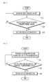
FIG. 3 is a block diagram illustrating a function of the active generation determining unit based on a soot amount according to the exemplary embodiment of the present invention. In a general situation, when the soot amount of approximately 6 to 8 g/l is accumulated in the DPF, the electronic control unit (ECU) automatically performs the DPF regeneration. However, in the driving condition, in which the DPF regeneration may not be progressed or driving is continued within a short driving time, the DPF regeneration is not normally performed but the soot may be continuously accumulated. According to an inventor, a maximum temperature in the DPF during the regeneration process is in direct proportion to the soot amount in the DPF at that time. When normal regeneration is not performed even though excessive soot is accumulated, subsequent regeneration may be progressed at an excessively high temperature, causing a problem to occur in the DPF system. In order to prevent the problem, when a predetermined amount of soot is accumulated in the DPF, the DPF active regeneration may be decided in order to protect the DPF system. - In detail, referring to a
block 310, the soot amount in the DPF is measured. In addition, in ablock 320, it is examined whether the soot amount in the DPF reaches a predetermined amount. As one example, the predetermined amount may be 6 to 8 g/1. When the soot amount in the DPF reaches the predetermined amount, the active regeneration is decided in ablock 330. When the soot amount in the DPF does not reach the predetermined amount, the process moves to theblock 310. -
FIG. 4 is a block diagram illustrating a function of an active generation determining unit based on a soot distribution in the DPF according to the exemplary embodiment of the present invention. In general, if the driving condition is advantageous in the DPF automatic regeneration, a total soot amount in the DPF is not significantly increased by the periodic automatic regeneration, but the soot distribution in the DPF may be negatively changed. That is, soot density is low at the center of the DPF having a relatively high exhaust temperature, but the soot density is high at an edge having a relatively low exhaust temperature. When regeneration occurs in this state, no problem occurs in the area having low soot density, but a soot oxidation temperature is increased at the edge having high soot density, and as a result, thermal stress is increased throughout the DPF, and as a result, a problem may occur in the DPF. This may become a phenomenon that threatens durability of the DPF system and in order to prevent the phenomenon, when an accumulated engine driving time reaches a predetermined value after the DPF regeneration is completed, the DPF active regeneration may be decided. - In detail, referring to a
block 410, the accumulated engine driving time after the DPF regeneration is measured. In addition, in ablock 420, it is examined whether the accumulated engine driving time reaches a predetermined value. As one example, the predetermined value may be approximately 30 to 80 hours. When the accumulated engine driving time reaches the predetermined value, the active regeneration is decided in ablock 430. When the accumulated engine driving time does not reach the predetermined value, the process returns to theblock 410. -
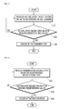
FIG. 5 is a block diagram illustrating a function of an active generation determining unit based on ash learning according to the exemplary embodiment of the present invention. In general, most particulates are oxidized to carbon dioxide (CO2) to evade the DPF in a gas state by the DPF regeneration. However, since ash components included in fuel and oil components are not oxidized, the ash components may be continuously accumulated in the DPF in an ash form. When the ash components are accumulated in the DPF, a calculation error may be caused at the time of calculating the soot amount calculated by differential pressure of the DPF. In order to reduce such an error, a calculation logic called ash learning that measures how much ash is accumulated in the DPF is used. However, the ash learning is performed under a steady driving condition by avoiding a transient driving condition in order to increase accuracy thereof. As one example, in the automobile DPF system, the ash learning is performed in cruise driving in an express way or a principal road. However, a commercial diesel engine is manufactured by an all speed governer method, and as a result, the all speed governer method is differentiated from an automobile minimum and maximum speed control type governer (min. & max. governer). In the case of the commercial diesel engine of the all speed governer method, it is difficult to create the steady driving condition, and as a result, it is difficult to achieve the ash learning. In the exemplary embodiment, in order to solve such a problem, when an accumulated engine driving time after the ash learning is successfully performed reaches a predetermined value, it is determined that driving is performed under an active regeneration condition under which the steady driving condition is possible to decide the active regeneration. - In detail, referring to a
block 510, the accumulated engine driving time after succeeding in the previously ash learning is measured. In ablock 520, it is examined whether the accumulated engine driving time reaches a predetermined value. The predetermined value may be approximately 800 to 1500 hours. When the accumulated engine driving time reaches the predetermined value, the active regeneration is decided in ablock 530. When the accumulated engine driving time does not reach the predetermined value, the process returns to theblock 510. -
FIG. 6 is a block diagram illustrating a function of the active generation determining unit based on a DPF regeneration frequency according to the exemplary embodiment of the present invention. In general, the DPF regeneration may be frequently repeated within a comparatively short time. As one example, when an absolute DPF regeneration time is short because an operating hour is 5 to 30 minutes after starting the engine, as another example, when the soot reaches the DPF regeneration condition within a short time because the DPF regeneration condition is not good and the soot in the DPF is not completely removed, and as yet another example, when the electronic control unit (ECU) wrongly calculates the soot amount due to an error in the DPF and the differential pressure sensor, the DPF regeneration frequency may be increased. - In this case, when a dilution amount of fuel in oil is more than approximately 10 to 15% to disable lubrication which is an original function of oil due to the frequent DPF regeneration, a problem may occur in the engine. That is, the engine over-runs, and as a result, the engine may be burnt. In order to prevent the engine problem, when a regeneration accumulation time for a predetermined engine driving time is more than a predetermined value, the active regeneration may be decided so that normal regeneration is progressed without neglecting further unsteady DPF regeneration.
- In detail, in a
block 610, the regeneration accumulation hour for the predetermined engine driving time is measured. The predetermined engine driving time may be approximately 50 to 100 hours as one example. In ablock 620, it is examined whether the regeneration accumulation hour reaches a predetermined value. As one example, the predetermined value may be approximately 200 to 400 hours. When the regeneration accumulation hour reaches the predetermined value, the active regeneration may be decided in ablock 630. When the regeneration accumulation hour does not reach the predetermined value, the process returns to theblock 610. - As described above, the active regeneration control device for a DPF according to the exemplary embodiment of the present invention includes an active regeneration determining unit, an active regeneration signal generating unit, and an active regeneration inducing unit. The active regeneration determining unit includes one selected from a group that consists of a DPF regeneration process based active regeneration determining unit, a soot amount based active regeneration determining unit, an in-DPF soot distribution based active regeneration determining unit, an ash learning based on active regeneration determining unit, and a DPF regeneration frequency based active regeneration determining unit. As a result, a time of active regeneration can be objectively optimized and judged with respect to a diesel automobile and diesel commercial equipment that are mounted with a manual switch for active regeneration of a DPF. As a result, durability of a DPF system itself can be maintained and a burden to an engine such as dilution of engine oil caused by abnormal regeneration of the DPF, or the like can be reduced.
- Although has been described with reference to the drawings and exemplary embodiments, it can be appreciated by those skilled in the art that various modifications and changes of the exemplary embodiments disclosed in the present invention can be made within the scope without departing from the spirit of the present invention disclosed in the appended claims.
- An active regeneration control device for a diesel particulate filter (DPF) according to the present invention may be used to induce a driver to perform DPF active regeneration at an optimized time.
Claims (6)
- An active regeneration control device for a diesel particulate filter (DPF), comprising:an active regeneration determining unit including one selected from a group that consists of a DPF regeneration process based active regeneration determining unit, a soot amount based active regeneration determining unit, an in-DPF soot distribution based active regeneration determining unit, an ash learning based on active regeneration determining unit, and a DPF regeneration frequency based active regeneration determining unit to judge an active regeneration time of the DPF;an active regeneration signal generating unit generating an active regeneration signal according to the decision of the active regeneration determining unit; andan active regeneration inducing unit inducing the active regeneration when the active regeneration is not performed after the active regeneration signal is generated.
- The device according to claim 1, wherein the DPF regeneration process based active regeneration determining unit extracts the number of DPF regeneration which is abnormally progressed based on the regeneration data based on previous regeneration data, and decides active regeneration when the number of DPF regeneration times which is abnormally progressed is equal to or more than a predetermined value.
- The device according to claim 1, wherein the soot amount based active regeneration determining unit decides active regeneration when a soot measurement amount reaches a predetermined value based on the soot measurement amount in the DPF.
- The device according to claim 1, wherein the in-DPF soot distribution based active regeneration determining unit decides active regeneration when an accumulated engine driving time measurement value reaches a predetermined value based on the accumulated engine driving time measurement value after the DPF regeneration.
- The device according to claim 1, wherein the ash learning based active regeneration determining unit decides active regeneration when an accumulated engine driving time measurement value reaches a predetermined value based on the accumulated engine driving time measurement value after succeeding in the previous ash learning.
- The device according to claim 1, wherein the DPF regeneration frequency based active regeneration determining unit decides active regeneration when the regeneration accumulation hour reaches a predetermined value based on a regeneration accumulation hour measurement value for a predetermined engine driving time.
Applications Claiming Priority (2)
| Application Number | Priority Date | Filing Date | Title |
|---|---|---|---|
| KR1020110140702A KR101880307B1 (en) | 2011-12-23 | 2011-12-23 | Forced Regeneration Control Machine for Diesel Particulate Filter |
| PCT/KR2012/010399 WO2013094894A1 (en) | 2011-12-23 | 2012-12-04 | Active regeneration control device for a diesel particulate filter |
Publications (3)
| Publication Number | Publication Date |
|---|---|
| EP2796681A1 true EP2796681A1 (en) | 2014-10-29 |
| EP2796681A4 EP2796681A4 (en) | 2015-08-12 |
| EP2796681B1 EP2796681B1 (en) | 2017-02-15 |
Family
ID=48668736
Family Applications (1)
| Application Number | Title | Priority Date | Filing Date |
|---|---|---|---|
| EP12861012.8A Active EP2796681B1 (en) | 2011-12-23 | 2012-12-04 | Active regeneration control device for a diesel particulate filter |
Country Status (5)
| Country | Link |
|---|---|
| US (1) | US9347348B2 (en) |
| EP (1) | EP2796681B1 (en) |
| KR (1) | KR101880307B1 (en) |
| CN (1) | CN104024591B (en) |
| WO (1) | WO2013094894A1 (en) |
Cited By (1)
| Publication number | Priority date | Publication date | Assignee | Title |
|---|---|---|---|---|
| EP3444455A4 (en) * | 2016-04-11 | 2019-04-24 | Bosch Corporation | FILTER REPRODUCTION SYSTEM, ECU AND FILTER REPRODUCTION PROGRAM |
Families Citing this family (10)
| Publication number | Priority date | Publication date | Assignee | Title |
|---|---|---|---|---|
| KR20150111186A (en) * | 2014-03-25 | 2015-10-05 | 대동공업주식회사 | Diesel Particulate Filter Regeneration Method and Diesel Particulate Filter Using the Same |
| US20160326934A1 (en) * | 2015-05-08 | 2016-11-10 | Hyundai Motor Company | Control method for informing a driver when to clean diesel particulate filter |
| JP6233450B2 (en) * | 2015-06-02 | 2017-11-22 | トヨタ自動車株式会社 | Control device for exhaust purification system |
| CN104929736B (en) * | 2015-07-13 | 2017-11-10 | 潍柴动力股份有限公司 | The control method of the vehicle-mounted Catalyst Regeneration of combustion gas |
| CN108798833B (en) * | 2018-05-25 | 2020-09-08 | 上海汽车集团股份有限公司 | Modeling Method of Ash Accumulation Model of Particle Trap |
| JP6969513B2 (en) * | 2018-07-17 | 2021-11-24 | 株式会社豊田自動織機 | Exhaust treatment device |
| CN111691958A (en) * | 2020-07-31 | 2020-09-22 | 江铃汽车股份有限公司 | Adaptive regeneration control strategy for gasoline particulate filter |
| CN112083715A (en) * | 2020-09-30 | 2020-12-15 | 中国汽车工程研究院股份有限公司 | Method for removing fault code by GPF |
| CN112943417B (en) * | 2021-04-29 | 2022-08-23 | 潍柴动力股份有限公司 | DPF regeneration control method, tail gas treatment system and vehicle |
| EP4717894A1 (en) * | 2024-09-30 | 2026-04-01 | Cummins Power Generation Inc. | System and method for maintaining operation of a regenerative soot filter |
Family Cites Families (12)
| Publication number | Priority date | Publication date | Assignee | Title |
|---|---|---|---|---|
| US5121601A (en) * | 1986-10-21 | 1992-06-16 | Kammel Refaat A | Diesel engine exhaust oxidizer |
| JP4273911B2 (en) | 2003-10-07 | 2009-06-03 | 三菱ふそうトラック・バス株式会社 | Vehicle exhaust purification system |
| JP3925484B2 (en) | 2003-10-29 | 2007-06-06 | マツダ株式会社 | Engine control device |
| JP3966272B2 (en) * | 2003-12-02 | 2007-08-29 | マツダ株式会社 | Engine exhaust purification system |
| JP2006037925A (en) * | 2004-07-30 | 2006-02-09 | Mazda Motor Corp | Engine exhaust purification system |
| JP3824003B2 (en) * | 2005-02-24 | 2006-09-20 | いすゞ自動車株式会社 | Exhaust gas purification system |
| US7631491B2 (en) | 2006-11-15 | 2009-12-15 | Detroit Diesel Corporation | Method and system for passive regeneration of compression ignition engine exhaust filters |
| JP2009138704A (en) * | 2007-12-10 | 2009-06-25 | Mitsubishi Fuso Truck & Bus Corp | Exhaust emission aftertreatment device |
| WO2010016077A1 (en) * | 2008-08-08 | 2010-02-11 | Pirelli & C. Eco Technology S.P.A. | Method and device for controlling the regeneration of a particulate filter |
| JP5155979B2 (en) * | 2009-10-21 | 2013-03-06 | ヤンマー株式会社 | diesel engine |
| US20120204537A1 (en) * | 2011-02-11 | 2012-08-16 | Caterpillar Inc. | Adaptive diesel particulate filter regeneration control and method |
| JP5658075B2 (en) | 2011-04-15 | 2015-01-21 | 日立建機株式会社 | Exhaust gas purification system for work equipment |
-
2011
- 2011-12-23 KR KR1020110140702A patent/KR101880307B1/en active Active
-
2012
- 2012-12-04 WO PCT/KR2012/010399 patent/WO2013094894A1/en not_active Ceased
- 2012-12-04 CN CN201280063632.1A patent/CN104024591B/en active Active
- 2012-12-04 EP EP12861012.8A patent/EP2796681B1/en active Active
- 2012-12-04 US US14/368,168 patent/US9347348B2/en active Active
Cited By (2)
| Publication number | Priority date | Publication date | Assignee | Title |
|---|---|---|---|---|
| EP3444455A4 (en) * | 2016-04-11 | 2019-04-24 | Bosch Corporation | FILTER REPRODUCTION SYSTEM, ECU AND FILTER REPRODUCTION PROGRAM |
| TWI708890B (en) * | 2016-04-11 | 2020-11-01 | 日商博世股份有限公司 | Filter regeneration system, ECU and filter regeneration program |
Also Published As
| Publication number | Publication date |
|---|---|
| EP2796681B1 (en) | 2017-02-15 |
| US9347348B2 (en) | 2016-05-24 |
| KR101880307B1 (en) | 2018-07-20 |
| CN104024591B (en) | 2016-07-13 |
| US20150000257A1 (en) | 2015-01-01 |
| CN104024591A (en) | 2014-09-03 |
| WO2013094894A1 (en) | 2013-06-27 |
| KR20130073054A (en) | 2013-07-03 |
| EP2796681A4 (en) | 2015-08-12 |
Similar Documents
| Publication | Publication Date | Title |
|---|---|---|
| EP2796681B1 (en) | Active regeneration control device for a diesel particulate filter | |
| JP5562697B2 (en) | DPF regeneration control device, regeneration control method, and regeneration support system | |
| US9482124B2 (en) | Method for detecting abnormally frequent diesel particulate filter regeneration, engine and exhaust aftertreatment system, and warning system and method | |
| US8209962B2 (en) | Diesel particulate filter soot permeability virtual sensors | |
| US20160326934A1 (en) | Control method for informing a driver when to clean diesel particulate filter | |
| US10519841B2 (en) | Method and system for monitoring of a physical quantity related to a particulate mass in at least one exhaust pipe | |
| US8186146B2 (en) | After-treatment component detection system | |
| RU2484266C2 (en) | Method and device for detection of combustion in particle filter | |
| US20150033837A1 (en) | Method for monitoring an exhaust system | |
| SE541017C2 (en) | A method and a system for determining a flow resistance across a particulate filter | |
| KR20180066487A (en) | Leak detection method of dpf by using a nitrogen oxide sensor | |
| JP6414802B2 (en) | Engine oil deterioration diagnosis device for diesel engine | |
| CN111335992B (en) | Method and device for diagnosing a particle filter arranged in an exhaust system of an internal combustion engine | |
| CN107345495A (en) | The frequent regeneration diagnostic method of diesel particulate filters | |
| KR101551083B1 (en) | Mehtod for monitoring fail of DPF system | |
| JP2006046245A (en) | Engine oil dilution monitoring system | |
| CN110005509A (en) | For detecting the method and system of the particle object amount of diesel particulate filters capture | |
| KR102114410B1 (en) | Method and system for determining performance of engine particle filter | |
| JP2021181768A (en) | Controls, internal combustion engine systems and diagnostic methods | |
| EP1762718A2 (en) | Process for regeneration of a particulate filter | |
| SE540518C2 (en) | Method and system for determining cleaning needs for a particle filter | |
| CN119084119A (en) | Method and apparatus for determining ash loading level in a fuel particulate filter | |
| JP2007023870A (en) | Judging method of regeneration time and ending time of diesel smoke filter | |
| JP2019044590A (en) | Exhaust purification device and internal combustion engine | |
| SE541035C2 (en) | System and method for determining the presence of fuel in an exhaust gas purification system |
Legal Events
| Date | Code | Title | Description |
|---|---|---|---|
| PUAI | Public reference made under article 153(3) epc to a published international application that has entered the european phase |
Free format text: ORIGINAL CODE: 0009012 |
|
| 17P | Request for examination filed |
Effective date: 20140624 |
|
| AK | Designated contracting states |
Kind code of ref document: A1 Designated state(s): AL AT BE BG CH CY CZ DE DK EE ES FI FR GB GR HR HU IE IS IT LI LT LU LV MC MK MT NL NO PL PT RO RS SE SI SK SM TR |
|
| DAX | Request for extension of the european patent (deleted) | ||
| RA4 | Supplementary search report drawn up and despatched (corrected) |
Effective date: 20150710 |
|
| RIC1 | Information provided on ipc code assigned before grant |
Ipc: F01N 3/023 20060101AFI20150706BHEP Ipc: F01N 9/00 20060101ALI20150706BHEP |
|
| GRAP | Despatch of communication of intention to grant a patent |
Free format text: ORIGINAL CODE: EPIDOSNIGR1 |
|
| INTG | Intention to grant announced |
Effective date: 20160809 |
|
| STAA | Information on the status of an ep patent application or granted ep patent |
Free format text: STATUS: GRANT OF PATENT IS INTENDED |
|
| GRAS | Grant fee paid |
Free format text: ORIGINAL CODE: EPIDOSNIGR3 |
|
| GRAA | (expected) grant |
Free format text: ORIGINAL CODE: 0009210 |
|
| STAA | Information on the status of an ep patent application or granted ep patent |
Free format text: STATUS: THE PATENT HAS BEEN GRANTED |
|
| AK | Designated contracting states |
Kind code of ref document: B1 Designated state(s): AL AT BE BG CH CY CZ DE DK EE ES FI FR GB GR HR HU IE IS IT LI LT LU LV MC MK MT NL NO PL PT RO RS SE SI SK SM TR |
|
| REG | Reference to a national code |
Ref country code: CH Ref legal event code: EP Ref country code: GB Ref legal event code: FG4D |
|
| REG | Reference to a national code |
Ref country code: IE Ref legal event code: FG4D |
|
| REG | Reference to a national code |
Ref country code: AT Ref legal event code: REF Ref document number: 868053 Country of ref document: AT Kind code of ref document: T Effective date: 20170315 |
|
| REG | Reference to a national code |
Ref country code: DE Ref legal event code: R096 Ref document number: 602012028817 Country of ref document: DE |
|
| REG | Reference to a national code |
Ref country code: NL Ref legal event code: MP Effective date: 20170215 |
|
| REG | Reference to a national code |
Ref country code: LT Ref legal event code: MG4D |
|
| REG | Reference to a national code |
Ref country code: AT Ref legal event code: MK05 Ref document number: 868053 Country of ref document: AT Kind code of ref document: T Effective date: 20170215 |
|
| PG25 | Lapsed in a contracting state [announced via postgrant information from national office to epo] |
Ref country code: FI Free format text: LAPSE BECAUSE OF FAILURE TO SUBMIT A TRANSLATION OF THE DESCRIPTION OR TO PAY THE FEE WITHIN THE PRESCRIBED TIME-LIMIT Effective date: 20170215 Ref country code: GR Free format text: LAPSE BECAUSE OF FAILURE TO SUBMIT A TRANSLATION OF THE DESCRIPTION OR TO PAY THE FEE WITHIN THE PRESCRIBED TIME-LIMIT Effective date: 20170516 Ref country code: HR Free format text: LAPSE BECAUSE OF FAILURE TO SUBMIT A TRANSLATION OF THE DESCRIPTION OR TO PAY THE FEE WITHIN THE PRESCRIBED TIME-LIMIT Effective date: 20170215 Ref country code: LT Free format text: LAPSE BECAUSE OF FAILURE TO SUBMIT A TRANSLATION OF THE DESCRIPTION OR TO PAY THE FEE WITHIN THE PRESCRIBED TIME-LIMIT Effective date: 20170215 Ref country code: NO Free format text: LAPSE BECAUSE OF FAILURE TO SUBMIT A TRANSLATION OF THE DESCRIPTION OR TO PAY THE FEE WITHIN THE PRESCRIBED TIME-LIMIT Effective date: 20170515 |
|
| PG25 | Lapsed in a contracting state [announced via postgrant information from national office to epo] |
Ref country code: LV Free format text: LAPSE BECAUSE OF FAILURE TO SUBMIT A TRANSLATION OF THE DESCRIPTION OR TO PAY THE FEE WITHIN THE PRESCRIBED TIME-LIMIT Effective date: 20170215 Ref country code: PT Free format text: LAPSE BECAUSE OF FAILURE TO SUBMIT A TRANSLATION OF THE DESCRIPTION OR TO PAY THE FEE WITHIN THE PRESCRIBED TIME-LIMIT Effective date: 20170615 Ref country code: BG Free format text: LAPSE BECAUSE OF FAILURE TO SUBMIT A TRANSLATION OF THE DESCRIPTION OR TO PAY THE FEE WITHIN THE PRESCRIBED TIME-LIMIT Effective date: 20170515 Ref country code: SE Free format text: LAPSE BECAUSE OF FAILURE TO SUBMIT A TRANSLATION OF THE DESCRIPTION OR TO PAY THE FEE WITHIN THE PRESCRIBED TIME-LIMIT Effective date: 20170215 Ref country code: ES Free format text: LAPSE BECAUSE OF FAILURE TO SUBMIT A TRANSLATION OF THE DESCRIPTION OR TO PAY THE FEE WITHIN THE PRESCRIBED TIME-LIMIT Effective date: 20170215 Ref country code: RS Free format text: LAPSE BECAUSE OF FAILURE TO SUBMIT A TRANSLATION OF THE DESCRIPTION OR TO PAY THE FEE WITHIN THE PRESCRIBED TIME-LIMIT Effective date: 20170215 Ref country code: NL Free format text: LAPSE BECAUSE OF FAILURE TO SUBMIT A TRANSLATION OF THE DESCRIPTION OR TO PAY THE FEE WITHIN THE PRESCRIBED TIME-LIMIT Effective date: 20170215 Ref country code: AT Free format text: LAPSE BECAUSE OF FAILURE TO SUBMIT A TRANSLATION OF THE DESCRIPTION OR TO PAY THE FEE WITHIN THE PRESCRIBED TIME-LIMIT Effective date: 20170215 |
|
| REG | Reference to a national code |
Ref country code: FR Ref legal event code: PLFP Year of fee payment: 6 |
|
| PG25 | Lapsed in a contracting state [announced via postgrant information from national office to epo] |
Ref country code: CZ Free format text: LAPSE BECAUSE OF FAILURE TO SUBMIT A TRANSLATION OF THE DESCRIPTION OR TO PAY THE FEE WITHIN THE PRESCRIBED TIME-LIMIT Effective date: 20170215 Ref country code: SK Free format text: LAPSE BECAUSE OF FAILURE TO SUBMIT A TRANSLATION OF THE DESCRIPTION OR TO PAY THE FEE WITHIN THE PRESCRIBED TIME-LIMIT Effective date: 20170215 Ref country code: RO Free format text: LAPSE BECAUSE OF FAILURE TO SUBMIT A TRANSLATION OF THE DESCRIPTION OR TO PAY THE FEE WITHIN THE PRESCRIBED TIME-LIMIT Effective date: 20170215 Ref country code: EE Free format text: LAPSE BECAUSE OF FAILURE TO SUBMIT A TRANSLATION OF THE DESCRIPTION OR TO PAY THE FEE WITHIN THE PRESCRIBED TIME-LIMIT Effective date: 20170215 |
|
| REG | Reference to a national code |
Ref country code: DE Ref legal event code: R097 Ref document number: 602012028817 Country of ref document: DE |
|
| PG25 | Lapsed in a contracting state [announced via postgrant information from national office to epo] |
Ref country code: SM Free format text: LAPSE BECAUSE OF FAILURE TO SUBMIT A TRANSLATION OF THE DESCRIPTION OR TO PAY THE FEE WITHIN THE PRESCRIBED TIME-LIMIT Effective date: 20170215 Ref country code: DK Free format text: LAPSE BECAUSE OF FAILURE TO SUBMIT A TRANSLATION OF THE DESCRIPTION OR TO PAY THE FEE WITHIN THE PRESCRIBED TIME-LIMIT Effective date: 20170215 Ref country code: PL Free format text: LAPSE BECAUSE OF FAILURE TO SUBMIT A TRANSLATION OF THE DESCRIPTION OR TO PAY THE FEE WITHIN THE PRESCRIBED TIME-LIMIT Effective date: 20170215 |
|
| PLBE | No opposition filed within time limit |
Free format text: ORIGINAL CODE: 0009261 |
|
| STAA | Information on the status of an ep patent application or granted ep patent |
Free format text: STATUS: NO OPPOSITION FILED WITHIN TIME LIMIT |
|
| 26N | No opposition filed |
Effective date: 20171116 |
|
| PG25 | Lapsed in a contracting state [announced via postgrant information from national office to epo] |
Ref country code: SI Free format text: LAPSE BECAUSE OF FAILURE TO SUBMIT A TRANSLATION OF THE DESCRIPTION OR TO PAY THE FEE WITHIN THE PRESCRIBED TIME-LIMIT Effective date: 20170215 |
|
| REG | Reference to a national code |
Ref country code: CH Ref legal event code: PL |
|
| REG | Reference to a national code |
Ref country code: IE Ref legal event code: MM4A |
|
| PG25 | Lapsed in a contracting state [announced via postgrant information from national office to epo] |
Ref country code: MT Free format text: LAPSE BECAUSE OF NON-PAYMENT OF DUE FEES Effective date: 20171204 Ref country code: LU Free format text: LAPSE BECAUSE OF NON-PAYMENT OF DUE FEES Effective date: 20171204 |
|
| REG | Reference to a national code |
Ref country code: FR Ref legal event code: PLFP Year of fee payment: 7 |
|
| REG | Reference to a national code |
Ref country code: BE Ref legal event code: MM Effective date: 20171231 |
|
| PG25 | Lapsed in a contracting state [announced via postgrant information from national office to epo] |
Ref country code: IE Free format text: LAPSE BECAUSE OF NON-PAYMENT OF DUE FEES Effective date: 20171204 |
|
| PG25 | Lapsed in a contracting state [announced via postgrant information from national office to epo] |
Ref country code: LI Free format text: LAPSE BECAUSE OF NON-PAYMENT OF DUE FEES Effective date: 20171231 Ref country code: CH Free format text: LAPSE BECAUSE OF NON-PAYMENT OF DUE FEES Effective date: 20171231 Ref country code: BE Free format text: LAPSE BECAUSE OF NON-PAYMENT OF DUE FEES Effective date: 20171231 |
|
| PG25 | Lapsed in a contracting state [announced via postgrant information from national office to epo] |
Ref country code: MC Free format text: LAPSE BECAUSE OF FAILURE TO SUBMIT A TRANSLATION OF THE DESCRIPTION OR TO PAY THE FEE WITHIN THE PRESCRIBED TIME-LIMIT Effective date: 20170215 Ref country code: HU Free format text: LAPSE BECAUSE OF FAILURE TO SUBMIT A TRANSLATION OF THE DESCRIPTION OR TO PAY THE FEE WITHIN THE PRESCRIBED TIME-LIMIT; INVALID AB INITIO Effective date: 20121204 |
|
| PG25 | Lapsed in a contracting state [announced via postgrant information from national office to epo] |
Ref country code: CY Free format text: LAPSE BECAUSE OF FAILURE TO SUBMIT A TRANSLATION OF THE DESCRIPTION OR TO PAY THE FEE WITHIN THE PRESCRIBED TIME-LIMIT Effective date: 20170215 |
|
| PG25 | Lapsed in a contracting state [announced via postgrant information from national office to epo] |
Ref country code: MK Free format text: LAPSE BECAUSE OF FAILURE TO SUBMIT A TRANSLATION OF THE DESCRIPTION OR TO PAY THE FEE WITHIN THE PRESCRIBED TIME-LIMIT Effective date: 20170215 |
|
| PG25 | Lapsed in a contracting state [announced via postgrant information from national office to epo] |
Ref country code: TR Free format text: LAPSE BECAUSE OF FAILURE TO SUBMIT A TRANSLATION OF THE DESCRIPTION OR TO PAY THE FEE WITHIN THE PRESCRIBED TIME-LIMIT Effective date: 20170215 |
|
| PG25 | Lapsed in a contracting state [announced via postgrant information from national office to epo] |
Ref country code: AL Free format text: LAPSE BECAUSE OF FAILURE TO SUBMIT A TRANSLATION OF THE DESCRIPTION OR TO PAY THE FEE WITHIN THE PRESCRIBED TIME-LIMIT Effective date: 20170215 Ref country code: IS Free format text: LAPSE BECAUSE OF FAILURE TO SUBMIT A TRANSLATION OF THE DESCRIPTION OR TO PAY THE FEE WITHIN THE PRESCRIBED TIME-LIMIT Effective date: 20170615 |
|
| REG | Reference to a national code |
Ref country code: DE Ref legal event code: R081 Ref document number: 602012028817 Country of ref document: DE Owner name: HYUNDAI DOOSAN INFRACORE CO., LTD., KR Free format text: FORMER OWNER: DOOSAN INFRACORE CO., LTD., DONG-GU, INCHEON, KR Ref country code: DE Ref legal event code: R081 Ref document number: 602012028817 Country of ref document: DE Owner name: HD HYUNDAI INFRACORE CO., LTD., KR Free format text: FORMER OWNER: DOOSAN INFRACORE CO., LTD., DONG-GU, INCHEON, KR |
|
| REG | Reference to a national code |
Ref country code: DE Ref legal event code: R081 Ref document number: 602012028817 Country of ref document: DE Owner name: HD HYUNDAI INFRACORE CO., LTD., KR Free format text: FORMER OWNER: HYUNDAI DOOSAN INFRACORE CO., LTD., INCHEON, KR |
|
| PGFP | Annual fee paid to national office [announced via postgrant information from national office to epo] |
Ref country code: FR Payment date: 20250930 Year of fee payment: 14 |
|
| PGFP | Annual fee paid to national office [announced via postgrant information from national office to epo] |
Ref country code: DE Payment date: 20250930 Year of fee payment: 14 |
|
| PGFP | Annual fee paid to national office [announced via postgrant information from national office to epo] |
Ref country code: GB Payment date: 20251001 Year of fee payment: 14 |
|
| PGFP | Annual fee paid to national office [announced via postgrant information from national office to epo] |
Ref country code: IT Payment date: 20251121 Year of fee payment: 14 |