EP2796665A2 - Abgasturbolader mit einer Welle aus unterschiedlichen Materialien - Google Patents
Abgasturbolader mit einer Welle aus unterschiedlichen Materialien Download PDFInfo
- Publication number
- EP2796665A2 EP2796665A2 EP14165000.2A EP14165000A EP2796665A2 EP 2796665 A2 EP2796665 A2 EP 2796665A2 EP 14165000 A EP14165000 A EP 14165000A EP 2796665 A2 EP2796665 A2 EP 2796665A2
- Authority
- EP
- European Patent Office
- Prior art keywords
- housing
- shaft
- compressor
- exhaust gas
- gas turbocharger
- Prior art date
- Legal status (The legal status is an assumption and is not a legal conclusion. Google has not performed a legal analysis and makes no representation as to the accuracy of the status listed.)
- Granted
Links
Images

Classifications
-
- F—MECHANICAL ENGINEERING; LIGHTING; HEATING; WEAPONS; BLASTING
- F01—MACHINES OR ENGINES IN GENERAL; ENGINE PLANTS IN GENERAL; STEAM ENGINES
- F01D—NON-POSITIVE DISPLACEMENT MACHINES OR ENGINES, e.g. STEAM TURBINES
- F01D5/00—Blades; Blade-carrying members; Heating, heat-insulating, cooling or antivibration means on the blades or the members
- F01D5/02—Blade-carrying members, e.g. rotors
- F01D5/026—Shaft to shaft connections
-
- F—MECHANICAL ENGINEERING; LIGHTING; HEATING; WEAPONS; BLASTING
- F01—MACHINES OR ENGINES IN GENERAL; ENGINE PLANTS IN GENERAL; STEAM ENGINES
- F01D—NON-POSITIVE DISPLACEMENT MACHINES OR ENGINES, e.g. STEAM TURBINES
- F01D5/00—Blades; Blade-carrying members; Heating, heat-insulating, cooling or antivibration means on the blades or the members
- F01D5/02—Blade-carrying members, e.g. rotors
- F01D5/04—Blade-carrying members, e.g. rotors for radial-flow machines or engines
- F01D5/043—Blade-carrying members, e.g. rotors for radial-flow machines or engines of the axial inlet- radial outlet, or vice versa, type
-
- F—MECHANICAL ENGINEERING; LIGHTING; HEATING; WEAPONS; BLASTING
- F02—COMBUSTION ENGINES; HOT-GAS OR COMBUSTION-PRODUCT ENGINE PLANTS
- F02C—GAS-TURBINE PLANTS; AIR INTAKES FOR JET-PROPULSION PLANTS; CONTROLLING FUEL SUPPLY IN AIR-BREATHING JET-PROPULSION PLANTS
- F02C6/00—Plural gas-turbine plants; Combinations of gas-turbine plants with other apparatus; Adaptations of gas- turbine plants for special use
- F02C6/04—Gas-turbine plants providing heated or pressurised working fluid for other apparatus, e.g. without mechanical power output
- F02C6/10—Gas-turbine plants providing heated or pressurised working fluid for other apparatus, e.g. without mechanical power output supplying working fluid to a user, e.g. a chemical process, which returns working fluid to a turbine of the plant
- F02C6/12—Turbochargers, i.e. plants for augmenting mechanical power output of internal-combustion piston engines by increase of charge pressure
-
- F—MECHANICAL ENGINEERING; LIGHTING; HEATING; WEAPONS; BLASTING
- F05—INDEXING SCHEMES RELATING TO ENGINES OR PUMPS IN VARIOUS SUBCLASSES OF CLASSES F01-F04
- F05D—INDEXING SCHEME FOR ASPECTS RELATING TO NON-POSITIVE-DISPLACEMENT MACHINES OR ENGINES, GAS-TURBINES OR JET-PROPULSION PLANTS
- F05D2220/00—Application
- F05D2220/40—Application in turbochargers
-
- F—MECHANICAL ENGINEERING; LIGHTING; HEATING; WEAPONS; BLASTING
- F05—INDEXING SCHEMES RELATING TO ENGINES OR PUMPS IN VARIOUS SUBCLASSES OF CLASSES F01-F04
- F05D—INDEXING SCHEME FOR ASPECTS RELATING TO NON-POSITIVE-DISPLACEMENT MACHINES OR ENGINES, GAS-TURBINES OR JET-PROPULSION PLANTS
- F05D2300/00—Materials; Properties thereof
- F05D2300/50—Intrinsic material properties or characteristics
- F05D2300/506—Hardness
Definitions
- the invention relates to an exhaust gas turbocharger.
- An exhaust gas turbocharger usually has a turbine housing, a bearing housing and a compressor housing.
- a turbine wheel is provided which is fixedly connected to a shaft.
- the shaft extends from the turbine housing, starting through the bearing housing into the compressor housing.
- the shaft is mounted, for example, using thrust bearings and radial bearings.
- a compressor wheel is attached to the shaft.
- the exhaust-gas mass flow of an internal combustion engine is conducted into the turbine housing and there causes the turbine wheel and the shaft connected to the turbine wheel to rotate. This rotational movement is transmitted to the compressor disposed in the compressor housing.
- the compressor impinges fresh air, compresses it and directs the compressed fresh air of the internal combustion engine, whose performance is increased by the compressed fresh air.
- the shaft of an exhaust gas turbocharger is usually made as turned parts in one piece and consists of a single material. Some small parts as well as the compressor wheel are mounted on the shaft on the compressor side and clamped axially by means of a shaft nut.
- the torque required must be transmitted between the turbine or the shaft and the compressor via this wave formation formed during this process. This torque is essentially dependent on the required compressor power and the inertia effects of the compressor-side parts during acceleration and deceleration.
- the maximum transmissible torque is transmitted by frictional forces due to the effective biasing force in the shaft and the effective coefficients of friction be determined. The preload force can be impressed up to the maximum permissible shaft strength. Consequently, the shaft strength limits the maximum transmissible torque. If the required torque is greater than the maximum transmittable torque, then there is an undesirable slippage of said wave association.
- the transmittable torque is to be increased, then it is possible to use a shaft made of a material with higher strength.
- a disadvantage of such a use of a shaft made of a material with higher strength is that the shaft or its material is usually not high temperature resistant. Since the shaft in the turbine housing is connected to the turbine wheel, which is very hot during operation of the exhaust gas turbocharger, a softening of the turbine shaft connection can occur due to these very high temperatures in the region of the turbine wheel. This leads to a malfunction of the exhaust gas turbocharger. Furthermore, use of a shaft of a higher strength material entails an undesirable increase in the cost of the exhaust gas turbocharger.
- the object of the invention is to provide an exhaust gas turbocharger whose shaft is better adapted to the conditions occurring during operation of the exhaust gas turbocharger than the waves known turbocharger.
- the shaft segment arranged in the turbine housing can be adapted to the conditions prevailing in the turbine housing by a suitable choice of material and the shaft segment arranged in the compressor housing can be adapted to the requirements prevailing in the compressor housing by a suitable selection of another material.
- the shaft segment arranged in the turbine housing can be selected from a highly heat-resistant material, since very high temperatures prevail in the turbine housing during operation of the exhaust gas turbocharger, since the hot exhaust gas of an internal combustion engine is directed into the turbine housing in order to drive the turbine wheel.
- the shaft segment arranged in the compressor housing can be selected from a material having a high strength in order to ensure that the highest possible torque can be transmitted from the turbine wheel or the shaft to the compressor wheel. It is not necessary that this material with high strength is also highly temperature-resistant, since in the region of the compressor housing significantly lower temperatures than in the turbine housing.
- the shaft of the exhaust gas turbocharger consists of two shaft segments, which are connected to each other in the region of the bearing housing in which the shaft is mounted.
- the two shaft segments may be connected to one another in the region of a turbine-side radial bearing, in the region of a compressor-side radial bearing, in the region of a spacer provided between the two radial bearings, in the region of a bearing collar, in the region of an oil deflector ring or in the region of a sealing bush.
- the shaft is composed of a plurality of interconnected shaft segments, of which a first shaft segment is arranged in the turbine housing and a second shaft segment in the compressor housing, wherein the shaft segment arranged in the turbine housing consists of a different material than the shaft segment arranged in the compressor housing.
- FIG. 1 shows a longitudinal sectional view of such exhaust gas turbocharger ATL, which has a turbine housing 1, a bearing housing 2 and a compressor housing 3. Furthermore, a shaft 4 is provided within said housing, wherein a turbine wheel 6 is mounted on this shaft 4 within the turbine housing 1. Further, a compressor 5 is mounted on the shaft 4 within the compressor housing 3. The shaft 4 is supported within the bearing housing using a turbine-side radial bearing 7 and a compressor-side radial bearing 8. Between these two radial bearings 7 and 8, a spacer 10 is provided. Furthermore, a bearing collar 11 is adjacent to the compressor-side radial bearing 8 in the direction of the compressor housing 3. In this bearing collar 11, a thrust bearing 14 is received. The bearing collar 11 is in the direction of the compressor housing 3, a ⁇ labweisring 12 adjacent. This in turn is in the direction of the compressor housing 3, a sealing bushing 13 adjacent.
- the shaft 4 is composed of a plurality of interconnected shaft segments, wherein in the FIG. 1 shown embodiment of two interconnected shaft segments 4a and 4b.
- the shaft segment 4 a is arranged in the turbine housing 1 and is connected there to the turbine wheel 6.
- the shaft segment 4b is arranged in the compressor housing 3 and connected there to the compressor wheel 5. Both shaft segments protrude into the bearing housing 2 and have a connection point 9 in the region of the bearing housing 2. Possible positions of this junction 9 in the bearing housing are described below with reference to Figures 2-4 explained in more detail.
- the shaft segment 4 a arranged in the turbine housing 1 consists of a different material than the shaft segment 4 b arranged in the compressor housing 3. Since very high temperatures prevail in the operation of the exhaust gas turbocharger in the region of the turbine housing 1 due to the hot exhaust gas mass flow of an internal combustion engine introduced therein, which may be up to 800 ° C., a highly heat-resistant material is used as the material for the shaft segment 4 a.
- a high-temperature resistant material with the material no. 1.4923 according to the classification EN 10269 used. It is a high-temperature chrome steel, which contains a molybdenum additive.
- the shaft segment 4b arranged in the compressor housing 3 is made of a material having high strength, preferably of a work-hardened material.
- the material of the shaft section 4b need not be high-temperature resistant material.
- connection point 9 of the two shaft segments 4a and 4b may be provided.
- FIG. 2 shows an enlarged view of the detail area D1 of FIG. 1 , In this enlarged view, a part of the bearing housing 2 and the compressor housing 3 are shown. It can be seen that in the FIG. 1 shown shaft portion 4a extends into the bearing housing 2 and there at a junction 9 with the in the FIG. 1 shaft portion 4b is shown, which also extends into the bearing housing 2. Furthermore, in the FIG. 2 the spacer 10, the compressor-side radial bearing 8, the bearing collar 11, the ⁇ labweisring 12, the sealing bushing 13, the turbine wheel 5 and provided in the compressor housing 3 radial bearing 15 is shown. The junction 9 of the two Shaft sections 4a and 4b are in this embodiment in the region of the compressor-side radial bearing 8, which is arranged in the bearing housing 2.
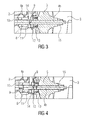
- FIG. 3 also shows an enlarged view of the detail area D1 of FIG. 1 , In this enlarged view, a part of the bearing housing 2 and the compressor housing 3 are shown. It can be seen that in the FIG. 1 shown shaft portion 4a extends into the bearing housing 2 and there at a junction 9 with the in the FIG. 1 shaft portion 4b is shown, which also extends into the bearing housing 2. Furthermore, in the FIG. 2 the spacer 10, the compressor-side radial bearing 8, the bearing collar 11, the ⁇ labweisring 12, the sealing bushing 13, the turbine wheel 5 and provided in the compressor housing 3 radial bearing 15 is shown. The connection point 9 of the two shaft sections 4a and 4b is in this embodiment in the region of the bearing collar 11.
- FIG. 4 shows an enlarged view of the detail area D1 of FIG. 1 , In this enlarged view, a part of the bearing housing 2 and the compressor housing 3 are shown. It can be seen that in the FIG. 1 shown shaft portion 4a extends into the bearing housing 2 and there at a junction 9 with the in the FIG. 1 shaft portion 4b is shown, which also extends into the bearing housing 2. Furthermore, in the FIG. 2 the spacer 10, the compressor-side radial bearing 8, the bearing collar 11, the ⁇ labweisring 12, the sealing bushing 13, the turbine 5 and provided in the compressor housing 3 radial bearing 15 is shown.
- the connection point 9 of the two shaft sections 4a and 4b are in the FIG. 4 shown three alternatives. The first alternative is to provide this connection point 9 in the region of the spacer 10. The second alternative is to provide the connection point 9 in the region of the oil deflecting ring 12. The third alternative is to provide the connection point 9 in the region of the sealing bushing 13.
- connection of the two shaft segments 4a and 4b for example, by welding, soldering or screwing. This can be done before or after finishing the shaft.
- the main advantage of the invention described above is that for the shaft the respective conditions of the turbine side and the compressor side individually adapted different materials can be used, so that the composite formed at a constant geometry over known exhaust gas turbochargers has a significant advantage in performance .
- the shaft diameter can be reduced, thereby achieving weight and cost savings.
Landscapes
- Engineering & Computer Science (AREA)
- Mechanical Engineering (AREA)
- General Engineering & Computer Science (AREA)
- Chemical & Material Sciences (AREA)
- Chemical Kinetics & Catalysis (AREA)
- General Chemical & Material Sciences (AREA)
- Combustion & Propulsion (AREA)
- Supercharger (AREA)
Abstract
Description
- Die Erfindung betrifft einen Abgasturbolader.
- Ein Abgasturbolader weist in der Regel ein Turbinengehäuse, ein Lagergehäuse und ein Verdichtergehäuse auf. Innerhalb des Turbinengehäuses ist ein Turbinenrad vorgesehen, das fest mit einer Welle verbunden ist. Die Welle erstreckt sich vom Turbinengehäuse ausgehend durch das Lagergehäuse bis in das Verdichtergehäuse. Im Lagergehäuse ist die Welle beispielsweise unter Verwendung von Axiallagern und Radiallagern gelagert. Im Verdichtergehäuse ist an der Welle ein Verdichterrad befestigt.
- Im Betrieb des Abgasturboladers wird der Abgasmassenstrom einer Brennkraftmaschine in das Turbinengehäuse geleitet und versetzt dort das Turbinenrad und die mit dem Turbinenrad verbundene Welle in eine Drehbewegung. Diese Drehbewegung wird auf das im Verdichtergehäuse angeordnete Verdichterrad übertragen. Das Verdichterrad saugt Frischluft an, verdichtet diese und leitet die verdichtete Frischluft der Brennkraftmaschine zu, deren Leistung durch die verdichtete Frischluft erhöht wird.
- Die Welle eines Abgasturboladers wird üblicherweise als Drehteile in einem Stück hergestellt und besteht aus einem einzigen Material. Auf die Welle werden verdichterseitig einige Kleinteile sowie das Verdichterrad montiert und mittels einer Wellenmutter axial verspannt. Über diesen dabei gebildeten Wellenverband muss im Betrieb des Abgasturboladers das benötigte Drehmoment zwischen der Turbine bzw. der Welle und dem Verdichter übertragen werden. Dieses Drehmoment ist im Wesentlichen von der benötigten Verdichterleistung und den Massenträgheitseffekten der verdichterseitigen Teile beim Beschleunigen bzw. Verzögern abhängig. Das maximal übertragbare Drehmoment wird durch Reibungskräfte übertragen, die durch die in der Welle wirksame Vorspannkraft und durch die wirksamen Reibungskoeffizienten bestimmt werden. Dabei kann die Vorspannkraft bis maximal zur zulässigen Wellenfestigkeit aufgeprägt werden. Folglich begrenzt die Wellenfestigkeit das maximal übertragbare Drehmoment. Ist das benötigte Drehmoment größer als das maximal übertragbare Drehmoment, dann kommt es zu einem unerwünschten Durchrutschen des genannten Wellenverbandes.
- Soll das übertragbare Drehmoment erhöht werden, dann besteht die Möglichkeit, eine Welle aus einem Werkstoff mit höherer Festigkeit zu verwenden. Ein Nachteil einer derartigen Verwendung einer Welle aus einem Werkstoff mit höherer Festigkeit besteht aber darin, dass die Welle bzw. deren Werkstoff in der Regel nicht hochtemperaturfest ist. Da die Welle im Turbinengehäuse mit dem im Betrieb des Abgasturboladers sehr heißen Turbinenrad verbunden ist, kann aufgrund dieser sehr hohen Temperaturen im Bereich des Turbinenrades eine Entfestigung der Turbine-Welle-Verbindung auftreten. Dies führt zu einer Funktionsunfähigkeit des Abgasturboladers. Des Weiteren ist eine Verwendung einer Welle aus einem Werkstoff mit höherer Festigkeit mit einer unerwünschten Erhöhung der Kosten des Abgasturboladers verbunden.
- Weitere alternative Möglichkeiten zur Erhöhung des übertragbaren Drehmoments bestehen darin, den Reibungskoeffizienten zwischen den genannten Bauteilen zu vergrößern oder den gesamten Wellenverband konstruktiv mit größeren Durchmessern und somit mit größeren Schraubenvorspannkräften zu gestalten. Dies ist jedoch ebenfalls mit einer unerwünschten Kostensteigerung verbunden. Des Weiteren wird das Gewicht des Abgasturboladers in unerwünschter Weise erhöht.
- Die Aufgabe der Erfindung besteht darin, einen Abgasturbolader anzugeben, dessen Welle an die im Arbeitsbetrieb des Abgasturboladers auftretenden Bedingungen besser angepasst ist als die Wellen bekannter Turbolader.
- Diese Aufgabe wird durch einen Abgasturbolader mit den im Patentanspruch 1 angegebenen Merkmalen gelöst. Vorteilhafte Ausgestaltungen und Weiterbildung eines Abgasturboladers mit den Merkmalen des Patentanspruchs 1 sind in den abhängigen Ansprüchen 2 - 13 angegeben.
- Die Vorteile der Erfindung bestehen insbesondere darin, dass das im Turbinengehäuse angeordnete Wellensegment durch eine geeignete Werkstoffauswahl an die im Turbinengehäuse herrschenden Bedingungen angepasst werden kann und das im Verdichtergehäuse angeordnete Wellensegment durch eine geeignete Auswahl eines anderen Werkstoffes an die im Verdichtergehäuse herrschenden Anforderungen angepasst werden kann. Insbesondere kann das im Turbinengehäuse angeordnete Wellensegment aus einem hochwarmfesten Material gewählt werden, da im Turbinengehäuse im Betrieb des Abgasturboladers sehr hohe Temperaturen herrschen, da das heiße Abgas einer Brennkraftmaschine in das Turbinengehäuse geleitet wird, um das Turbinenrad anzutreiben. Des Weiteren kann das im Verdichtergehäuse angeordnete Wellensegment aus einem Material mit hoher Festigkeit gewählt werden, um sicherzustellen, dass ein möglichst hohes Drehmoment vom Turbinenrad bzw. der Welle auf das Verdichterrad übertragen werden kann. Es ist nicht erforderlich, dass dieses Material mit hoher Festigkeit auch hoch temperaturfest ist, da im Bereich des Verdichtergehäuses deutlich niedrigere Temperaturen vorliegen als im Turbinengehäuse.
- Vorzugsweise besteht die Welle des Abgasturboladers aus zwei Wellensegmenten, die im Bereich des Lagergehäuses, in welchem die Welle gelagert ist, miteinander verbunden sind. Beispielsweise können die beiden Wellensegmente im Bereich eines turbinenseitigen Radiallagers, im Bereich eines verdichterseitigen Radiallagers, im Bereich eines zwischen den beiden Radiallagern vorgesehenen Abstandshalters, im Bereich eines Lagerbundes, im Bereich eines Ölabweisringes oder im Bereich einer Dichtungsbuchse miteinander verbunden sein. Dies wird nachfolgend anhand der Zeichnungen näher erläutert.
- Es zeigt
- Figur 1
- eine Längsschnittdarstellung eines Abgasturboladers, welcher ein Turbinengehäuse, ein Lagergehäuse und ein Verdichtergehäuse aufweist,
- Figur 2
- eine vergrößerte Darstellung des Detailbereiches D1 von
Figur 1 zur Veranschaulichung einer möglichen Verbindungsstelle für die beiden Wellensegmente der Welle des Abgasturboladers, - Figur 3
- eine vergrößerte Darstellung des Detailbereiches D1 von
Figur 1 zur Veranschaulichung einer weiteren möglichen Verbindungsstelle für die beiden Wellensegmente der Welle des Abgasturboladers und - Figur 4
- eine vergrößerte Darstellung des Detailbereiches D1 von
Figur 1 zur Veranschaulichung dreier weiterer möglicher Verbindungsstellen für die beiden Wellensegmente der Welle des Abgasturboladers. - Gemäß der vorliegenden Erfindung ist bei einem Abgasturbolader, der ein Turbinengehäuse, ein Lagergehäuse und ein Verdichtergehäuse aufweist und welcher mit einer Welle versehen ist, die im Lagergehäuse gelagert ist und die innerhalb des Verdichtergehäuses mit einem Verdichterrad und innerhalb des Turbinengehäuses mit einem Turbinenrad verbunden ist, die Welle aus mehreren miteinander verbundenen Wellensegmenten zusammengesetzt, von denen ein erstes Wellensegment im Turbinengehäuse und ein zweites Wellensegment im Verdichtergehäuse angeordnet ist, wobei das im Turbinengehäuse angeordnete Wellensegment aus einem anderen Material besteht als das im Verdichtergehäuse angeordnete Wellensegment.
- Die
Figur 1 zeigt eine Längsschnittdarstellung eines derartigen Abgasturboladers ATL, welcher ein Turbinengehäuse 1, ein Lagergehäuse 2 und ein Verdichtergehäuse 3 aufweist. Des Weiteren ist innerhalb der genannten Gehäuse eine Welle 4 vorgesehen, wobei auf dieser Welle 4 innerhalb des Turbinengehäuses 1 ein Turbinenrad 6 befestigt ist. Ferner ist auf der Welle 4 innerhalb des Verdichtergehäuses 3 ein Verdichterrad 5 befestigt. Die Welle 4 ist innerhalb des Lagergehäuses unter Verwendung eines turbinenseitigen Radiallagers 7 und eines verdichterseitigen Radiallagers 8 gelagert. Zwischen diesen beiden Radiallagern 7 und 8 ist ein Abstandshalter 10 vorgesehen. Des Weiteren ist dem verdichterseitigen Radiallager 8 in Richtung des Verdichtergehäuses 3 ein Lagerbund 11 benachbart. In diesen Lagerbund 11 ist ein Axiallager 14 aufgenommen. Dem Lagerbund 11 ist in Richtung des Verdichtergehäuses 3 ein Ölabweisring 12 benachbart. Diesem wiederum ist in Richtung des Verdichtergehäuses 3 eine Dichtungsbuchse 13 benachbart. - Die Welle 4 ist aus mehreren miteinander verbundenen Wellensegmenten zusammengesetzt, bei dem in der
Figur 1 gezeigten Ausführungsbeispiel aus zwei miteinander verbundenen Wellensegmenten 4a und 4b. Das Wellensegment 4a ist im Turbinengehäuse 1 angeordnet und ist dort mit dem Turbinenrad 6 verbunden. Das Wellensegment 4b ist im Verdichtergehäuse 3 angeordnet und dort mit dem Verdichterrad 5 verbunden. Beide Wellensegmente ragen in das Lagergehäuse 2 hinein und weisen im Bereich des Lagergehäuses 2 eine Verbindungsstelle 9 auf. Mögliche Positionierungen dieser Verbindungsstelle 9 im Lagergehäuse werden unten anhand derFiguren 2 - 4 näher erläutert. - Das im Turbinengehäuse 1 angeordnete Wellensegment 4a besteht aus einem anderen Material als das im Verdichtergehäuse 3 angeordnete Wellensegment 4b. Da im Betrieb des Abgasturboladers im Bereich des Turbinengehäuses 1 aufgrund des in dieses eingeleiteten heißen Abgasmassenstromes einer Brennkraftmaschine sehr hohe Temperaturen herrschen, die bis zu 800°C betragen können, wird als Material für das Wellensegment 4a ein hochwarmfestes Material verwendet. Beispielsweise wird ein hochwarmfestes Material mit der Werkstoff-Nr. 1.4923 gemäß der Klassifizierung EN 10269 verwendet. Dabei handelt es sich um einen hochwarmfesten Chrom-Stahl, welcher einen Molybdänzusatz enthält.
- Das im Verdichtergehäuse 3 angeordnete Wellensegment 4b besteht aus einem Material mit hoher Festigkeit, vorzugsweise aus einem kaltverfestigten Werkstoff. Beispielsweise wird als Material für das Wellensegment 4b ein Vergütungsstahl mit der Werkstoff-Nr. 1.7225 oder 1.7227 gemäß der Klassifizierung EN 10269 verwendet. Dazu gehören der Vergütungsstahl 42CrMo4 sowie der Vergütungsstahl 42CrMoS4, bei denen es sich um Werkstoffe handelt, die eine hohe Festigkeit bei gleichzeitig hoher Zähigkeit aufweisen.
- Da die im Betrieb des Abgasturboladers im Bereich des Verdichtergehäuses auftretenden Temperaturen wesentlich niedriger sind als die im Bereich des Turbinengehäuses auftretenden Temperaturen, muss es sich bei dem Material des Wellenabschnittes 4b nicht um hochwarmfestes Material handeln.
- Durch die Wahl eines Materials mit hoher Festigkeit für den Wellenabschnitt 4b wird in vorteilhafter Weise erreicht, dass das von der Welle auf das Verdichterrad übertragene Drehmoment hoch ist, so dass die mittels des Turboladers erreichbare Leistungssteigerung der Brennkraftmaschine im Vergleich zu bekannten Abgasturboladern erhöht ist.
- Nachfolgend werden anhand der
Figuren 2 - 4 Beispiele gezeigt, an welchen Positionen des Lagergehäuses 2 die Verbindungsstelle 9 der beiden Wellensegmente 4a und 4b vorgesehen sein kann. - Die
Figur 2 zeigt eine vergrößerte Darstellung des Detailbereiches D1 vonFigur 1 . In dieser vergrößerten Darstellung sind ein Teil des Lagergehäuses 2 und des Verdichtergehäuses 3 gezeigt. Es ist ersichtlich, dass der in derFigur 1 gezeigte Wellenabschnitt 4a sich bis in das Lagergehäuse 2 erstreckt und dort an einer Verbindungsstelle 9 mit dem in derFigur 1 gezeigten Wellenabschnitt 4b verbunden ist, welcher ebenfalls bis in das Lagergehäuse 2 hineinreicht. Des Weiteren sind in derFigur 2 der Abstandshalter 10, das verdichterseitige Radiallager 8, der Lagerbund 11, der Ölabweisring 12, die Dichtungsbuchse 13, das Turbinenrad 5 und ein im Verdichtergehäuse 3 vorgesehenes Radiallager 15 gezeigt. Die Verbindungsstelle 9 der beiden Wellenabschnitte 4a und 4b befindet sich bei diesem Ausführungsbeispiel im Bereich des verdichterseitigen Radiallagers 8, welches im Lagergehäuse 2 angeordnet ist. - Die
Figur 3 zeigt ebenfalls eine vergrößerte Darstellung des Detailbereiches D1 vonFigur 1 . In dieser vergrößerten Darstellung sind ein Teil des Lagergehäuses 2 und des Verdichtergehäuses 3 gezeigt. Es ist ersichtlich, dass der in derFigur 1 gezeigte Wellenabschnitt 4a sich bis in das Lagergehäuse 2 erstreckt und dort an einer Verbindungsstelle 9 mit dem in derFigur 1 gezeigten Wellenabschnitt 4b verbunden ist, welcher ebenfalls bis in das Lagergehäuse 2 hineinreicht. Des Weiteren sind in derFigur 2 der Abstandshalter 10, das verdichterseitige Radiallager 8, der Lagerbund 11, der Ölabweisring 12, die Dichtungsbuchse 13, das Turbinenrad 5 und ein im Verdichtergehäuse 3 vorgesehenes Radiallager 15 gezeigt. Die Verbindungsstelle 9 der beiden Wellenabschnitte 4a und 4b befindet sich bei diesem Ausführungsbeispiel im Bereich des Lagerbundes 11. - Auch die
Figur 4 zeigt eine vergrößerte Darstellung des Detailbereiches D1 vonFigur 1 . In dieser vergrößerten Darstellung sind ein Teil des Lagergehäuses 2 und des Verdichtergehäuses 3 gezeigt. Es ist ersichtlich, dass der in derFigur 1 gezeigte Wellenabschnitt 4a sich bis in das Lagergehäuse 2 erstreckt und dort an einer Verbindungsstelle 9 mit dem in derFigur 1 gezeigten Wellenabschnitt 4b verbunden ist, welcher ebenfalls bis in das Lagergehäuse 2 hineinreicht. Des Weiteren sind in derFigur 2 der Abstandshalter 10, das verdichterseitige Radiallager 8, der Lagerbund 11, der Ölabweisring 12, die Dichtungsbuchse 13, das Turbinenrad 5 und ein im Verdichtergehäuse 3 vorgesehene Radiallager 15 gezeigt. Für die Verbindungsstelle 9 der beiden Wellenabschnitte 4a und 4b sind in derFigur 4 drei Alternativen aufgezeigt. Die erste Alternative besteht darin, diese Verbindungsstelle 9 im Bereich des Abstandshalters 10 vorzusehen. Die zweite Alternative besteht darin, die Verbindungsstelle 9 im Bereich des Ölabweisringes 12 vorzusehen. Die dritte Alternative besteht darin, die Verbindungsstelle 9 im Bereich der Dichtungsbuchse 13 vorzusehen. - Die Verbindung der beiden Wellensegmente 4a und 4b erfolgt beispielsweise durch ein Verschweißen, ein Verlöten oder ein Verschrauben. Dies kann vor oder nach dem Fertigbearbeiten der Welle geschehen.
- Der wesentliche Vorteil der vorstehend beschriebenen Erfindung besteht nach alledem darin, dass für die Welle den jeweiligen Bedingungen der Turbinenseite und der Verdichterseite individuell angepasste unterschiedliche Werkstoffe eingesetzt werden können, so dass der gebildete Gesamtverband bei gleichbleibender Geometrie gegenüber bekannten Abgasturboladern einen deutlichen Vorteil in der Performance hat. Andererseits kann bei feststehender Vorspannkraft der Wellendurchmesser reduziert werden, wodurch Gewichts- und Kosteneinsparungen erzielt werden.
Claims (13)
- Abgasturbolader, welcher ein Turbinengehäuse, ein Lagergehäuse und ein Verdichtergehäuse aufweist und welcher mit einer Welle versehen ist, die im Lagergehäuse gelagert ist und die innerhalb des Verdichtergehäuses mit einem Verdichterrad und innerhalb des Turbinengehäuses mit einem Turbinenrad verbunden ist, dadurch gekennzeichnet, dass die Welle (4) aus mehreren miteinander verbundenen Wellensegmenten (4a,4b) zusammengesetzt ist, von denen ein erstes Wellensegment (4a) im Turbinengehäuse (1) und ein zweites Wellensegment (4b) im Verdichtergehäuse (3) angeordnet ist und das im Turbinengehäuse angeordnete Wellensegment aus einem anderen Material besteht als das im Verdichtergehäuse angeordnete Wellensegment.
- Abgasturbolader nach Anspruch 1, dadurch gekennzeichnet, dass das im Turbinengehäuse (1) angeordnete Wellensegment (4a) aus einem hochwarmfesten Material besteht.
- Abgasturbolader nach Anspruch 2, dadurch gekennzeichnet, dass das im Turbinengehäuse (1) angeordnete Wellensegment (4a) aus einem hochwarmfesten Material mit der Werkstoff-Nr. 1.4923 gemäß der Klassifizierung EN 10269 besteht.
- Abgasturbolader nach einem der vorhergehenden Ansprüche, dadurch gekennzeichnet, dass das im Verdichtergehäuse (3) angeordnete Wellensegment (4b) aus einem Material mit hoher Festigkeit besteht.
- Abgasturbolader nach Anspruch 4, dadurch gekennzeichnet, dass das im Verdichtergehäuse (3) angeordnete Wellensegment (4b) aus einem kaltverfestigten Werkstoff besteht.
- Abgasturbolader nach Anspruch 4 oder 5, dadurch gekennzeichnet, dass das im Verdichtergehäuse (3) angeordnete Wellensegment (4b) aus einem Material mit der Werkstoff-Nr. 1.7225 oder 1.7227 gemäß der Klassifizierung EN 10269 besteht.
- Abgasturbolader nach einem der vorhergehenden Ansprüche, dadurch gekennzeichnet, dass die Welle (4) aus zwei Wellensegmenten (4a,4b) zusammengesetzt ist, die in das Lagergehäuse (2) hineinragen und im Bereich des Lagergehäuses (2) miteinander verbunden sind.
- Abgasturbolader nach Anspruch 7, dadurch gekennzeichnet, dass die beiden Wellensegmente (4a,4b) im Bereich des Lagergehäuses (2) miteinander verschweißt, verlötet oder verschraubt sind.
- Abgasturbolader nach Anspruch 7 oder 8, dadurch gekennzeichnet, dass im Lagergehäuse (2) ein turbinenseitiges Radiallager (7) und ein verdichterseitiges Radiallager (8) vorgesehen sind und die Verbindungsstelle (9) der beiden Wellensegmente (4a,4b) im Bereich des turbinenseitigen Radiallagers (7) oder des verdichterseitigen Radiallagers (8) angeordnet ist.
- Abgasturbolader nach Anspruch 7 oder 8, dadurch gekennzeichnet, dass im Lagergehäuse (2) ein turbinenseitiges Radiallager (7) und ein verdichterseitiges Radiallager (8) vorgesehen sind, welche durch einen Abstandshalter (10) voneinander beabstandet sind, und dass die Verbindungsstelle (9) zwischen den beiden Wellensegmenten (4a,4b) im Bereich des Abstandshalters (10) angeordnet ist.
- Abgasturbolader nach Anspruch 7 oder 8, dadurch gekennzeichnet, dass im Lagergehäuse (2) ein verdichterseitiges Radiallager (8) angeordnet ist, dem in Richtung des Verdichtergehäuses (3) ein Lagerbund (11) benachbart ist und dass die Verbindungsstelle (9) der beiden Wellensegmente (4a,4b) im Bereich des Lagerbundes (11) angeordnet ist.
- Abgasturbolader nach Anspruch 7 oder 8, dadurch gekennzeichnet, dass das Lagergehäuse (2) in Richtung des Verdichtergehäuses (3) einen Ölabweisring (12) aufweist und dass die Verbindungsstelle (9) der beiden Wellensegmente (4a,4b) im Bereich des Ölabweisringes (12) angeordnet ist.
- Abgasturbolader nach Anspruch 7 oder 8, dadurch gekennzeichnet, dass das Lagergehäuse (2) in Richtung des Verdichtergehäuses (3) eine Dichtungsbuchse (13) aufweist und dass die Verbindungsstelle (9) der beiden Wellensegmente (4a,4b) im Bereich der Dichtungsbuchse (13) angeordnet ist.
Applications Claiming Priority (1)
| Application Number | Priority Date | Filing Date | Title |
|---|---|---|---|
| DE102013207454.9A DE102013207454A1 (de) | 2013-04-24 | 2013-04-24 | Abgasturbolader mit einer Welle aus unterschiedlichen Materialien |
Publications (4)
| Publication Number | Publication Date |
|---|---|
| EP2796665A2 true EP2796665A2 (de) | 2014-10-29 |
| EP2796665A3 EP2796665A3 (de) | 2014-12-03 |
| EP2796665B1 EP2796665B1 (de) | 2019-07-24 |
| EP2796665B8 EP2796665B8 (de) | 2019-12-18 |
Family
ID=50479141
Family Applications (1)
| Application Number | Title | Priority Date | Filing Date |
|---|---|---|---|
| EP14165000.2A Active EP2796665B8 (de) | 2013-04-24 | 2014-04-16 | Abgasturbolader mit einer Welle aus unterschiedlichen Materialien |
Country Status (2)
| Country | Link |
|---|---|
| EP (1) | EP2796665B8 (de) |
| DE (1) | DE102013207454A1 (de) |
Cited By (1)
| Publication number | Priority date | Publication date | Assignee | Title |
|---|---|---|---|---|
| WO2022053484A1 (de) * | 2020-09-08 | 2022-03-17 | Federal-Mogul Nürnberg GmbH | Kolben für einen verbrennungsmotor, verbrennungsmotor mit einem kolben und verwendung einer eisenbasierten legierung |
Families Citing this family (1)
| Publication number | Priority date | Publication date | Assignee | Title |
|---|---|---|---|---|
| DE102020118424A1 (de) | 2020-07-13 | 2022-01-13 | Schaeffler Technologies AG & Co. KG | Wälzlager für einen Turbolader |
Family Cites Families (6)
| Publication number | Priority date | Publication date | Assignee | Title |
|---|---|---|---|---|
| EP1002935A1 (de) * | 1998-11-20 | 2000-05-24 | Asea Brown Boveri AG | TiAl-Rotor einer Strömungsmaschine und Herstellungsverfahren |
| US20060067824A1 (en) * | 2004-09-30 | 2006-03-30 | O'hara Stephen J | Turbocharger with titanium component |
| DE102004057138A1 (de) * | 2004-11-26 | 2006-06-08 | Daimlerchrysler Ag | Abgasturbolader für einen Verbrennungsmotor |
| DE102007048789A1 (de) * | 2007-10-10 | 2009-05-20 | Access E.V. | Füge- und Materialauftragsverfahren für ein Werkstück mit einem Werkstückbereich aus einer Titanaluminid-Legierung |
| DE102008008857B4 (de) * | 2008-02-13 | 2017-06-22 | Daimler Ag | Verbindung einer Welle mit einem Rotationsbauteil |
| DE102009049695A1 (de) * | 2009-06-04 | 2011-01-13 | Continental Automotive Gmbh | Verfahren zur Herstellung eines Läufers eines Turboladers |
-
2013
- 2013-04-24 DE DE102013207454.9A patent/DE102013207454A1/de not_active Withdrawn
-
2014
- 2014-04-16 EP EP14165000.2A patent/EP2796665B8/de active Active
Non-Patent Citations (1)
| Title |
|---|
| None |
Cited By (1)
| Publication number | Priority date | Publication date | Assignee | Title |
|---|---|---|---|---|
| WO2022053484A1 (de) * | 2020-09-08 | 2022-03-17 | Federal-Mogul Nürnberg GmbH | Kolben für einen verbrennungsmotor, verbrennungsmotor mit einem kolben und verwendung einer eisenbasierten legierung |
Also Published As
| Publication number | Publication date |
|---|---|
| EP2796665B1 (de) | 2019-07-24 |
| EP2796665B8 (de) | 2019-12-18 |
| EP2796665A3 (de) | 2014-12-03 |
| DE102013207454A1 (de) | 2014-10-30 |
Similar Documents
| Publication | Publication Date | Title |
|---|---|---|
| DE102017127876A1 (de) | Planetengetriebe und Gleitlagerstift für ein Planetengetriebe | |
| EP2209969B1 (de) | Ladeeinrichtung | |
| EP3034832B1 (de) | Ladeeinrichtung | |
| DE112013001173T5 (de) | Systeme und Verfahren zum Schutz eines Turboladeraluminiumlagergehäuses | |
| EP3199758B1 (de) | Rotor in blisk- oder bling-bauweise eines flugtriebwerks | |
| WO2015000629A1 (de) | Läufer für eine turboladereinrichtung, turboladereinrichtung mit einem läufer und welle für einen solchen läufer | |
| EP3034781B1 (de) | Abgasturbolader | |
| EP3548705B1 (de) | Turbolader | |
| EP3000984A1 (de) | Leitschaufelverstellvorrichtung einer gasturbine | |
| DE112016004554T5 (de) | Betätigungsvorrichtung für variable Statorschaufeln | |
| DE102008014680A1 (de) | Leitgitteranordnung eines Abgasturboladers, Abgasturbolader und Verfahren zur Herstellung einer Leitgitteranordnung | |
| DE102010013702A1 (de) | Turbine, Abgasturbolader, Kraftfahrzeug und Verfahren zur Montage einer derartigen Turbine | |
| EP1676980B1 (de) | Turbolader mit variabler Turbinengeometrie | |
| EP0806547B1 (de) | Axialturbine eines Abgasturboladers | |
| EP3456999A1 (de) | Planetengetriebevorrichtung für eine strömungsmaschine | |
| DE102008020732A1 (de) | Ladeeinrichtung | |
| EP2796665B1 (de) | Abgasturbolader mit einer Welle aus unterschiedlichen Materialien | |
| DE102008046009A1 (de) | Ladeeinrichtung | |
| EP2730751A2 (de) | Leitschaufelverstellvorrichtung einer Gasturbine | |
| WO2018197213A1 (de) | Turbolader mit sollbruchstelle für eine brennkraftmaschine | |
| DE102018106484A1 (de) | Getriebefan-Triebwerk und Keilwellenanordnung | |
| EP1965037A1 (de) | Axiale und radiale Lagerung des Stellrings für Eintrittsleitapparate bei Heissgasexpandern | |
| WO2014194990A1 (de) | Verstellvorrichtung für einen abgasturbolader | |
| DE102016103115A1 (de) | Laufzeug für einen Abgasturbolader | |
| DE102017216621A1 (de) | Rotor für einen Turbolader |
Legal Events
| Date | Code | Title | Description |
|---|---|---|---|
| PUAI | Public reference made under article 153(3) epc to a published international application that has entered the european phase |
Free format text: ORIGINAL CODE: 0009012 |
|
| 17P | Request for examination filed |
Effective date: 20140416 |
|
| AK | Designated contracting states |
Kind code of ref document: A2 Designated state(s): AL AT BE BG CH CY CZ DE DK EE ES FI FR GB GR HR HU IE IS IT LI LT LU LV MC MK MT NL NO PL PT RO RS SE SI SK SM TR |
|
| AX | Request for extension of the european patent |
Extension state: BA ME |
|
| PUAL | Search report despatched |
Free format text: ORIGINAL CODE: 0009013 |
|
| AK | Designated contracting states |
Kind code of ref document: A3 Designated state(s): AL AT BE BG CH CY CZ DE DK EE ES FI FR GB GR HR HU IE IS IT LI LT LU LV MC MK MT NL NO PL PT RO RS SE SI SK SM TR |
|
| AX | Request for extension of the european patent |
Extension state: BA ME |
|
| RIC1 | Information provided on ipc code assigned before grant |
Ipc: F01D 5/04 20060101AFI20141024BHEP Ipc: F02C 6/12 20060101ALI20141024BHEP Ipc: F01D 5/02 20060101ALI20141024BHEP |
|
| R17P | Request for examination filed (corrected) |
Effective date: 20150603 |
|
| RBV | Designated contracting states (corrected) |
Designated state(s): AL AT BE BG CH CY CZ DE DK EE ES FI FR GB GR HR HU IE IS IT LI LT LU LV MC MK MT NL NO PL PT RO RS SE SI SK SM TR |
|
| STAA | Information on the status of an ep patent application or granted ep patent |
Free format text: STATUS: EXAMINATION IS IN PROGRESS |
|
| 17Q | First examination report despatched |
Effective date: 20180215 |
|
| GRAP | Despatch of communication of intention to grant a patent |
Free format text: ORIGINAL CODE: EPIDOSNIGR1 |
|
| STAA | Information on the status of an ep patent application or granted ep patent |
Free format text: STATUS: GRANT OF PATENT IS INTENDED |
|
| INTG | Intention to grant announced |
Effective date: 20190226 |
|
| GRAS | Grant fee paid |
Free format text: ORIGINAL CODE: EPIDOSNIGR3 |
|
| GRAA | (expected) grant |
Free format text: ORIGINAL CODE: 0009210 |
|
| STAA | Information on the status of an ep patent application or granted ep patent |
Free format text: STATUS: THE PATENT HAS BEEN GRANTED |
|
| AK | Designated contracting states |
Kind code of ref document: B1 Designated state(s): AL AT BE BG CH CY CZ DE DK EE ES FI FR GB GR HR HU IE IS IT LI LT LU LV MC MK MT NL NO PL PT RO RS SE SI SK SM TR |
|
| REG | Reference to a national code |
Ref country code: GB Ref legal event code: FG4D Free format text: NOT ENGLISH |
|
| REG | Reference to a national code |
Ref country code: CH Ref legal event code: EP |
|
| REG | Reference to a national code |
Ref country code: DE Ref legal event code: R096 Ref document number: 502014012261 Country of ref document: DE |
|
| REG | Reference to a national code |
Ref country code: AT Ref legal event code: REF Ref document number: 1158428 Country of ref document: AT Kind code of ref document: T Effective date: 20190815 |
|
| REG | Reference to a national code |
Ref country code: IE Ref legal event code: FG4D Free format text: LANGUAGE OF EP DOCUMENT: GERMAN |
|
| REG | Reference to a national code |
Ref country code: NL Ref legal event code: MP Effective date: 20190724 |
|
| REG | Reference to a national code |
Ref country code: CH Ref legal event code: PK Free format text: BERICHTIGUNG B8 |
|
| REG | Reference to a national code |
Ref country code: DE Ref legal event code: R081 Ref document number: 502014012261 Country of ref document: DE Owner name: VITESCO TECHNOLOGIES GMBH, DE Free format text: FORMER OWNER: CONTINENTAL AUTOMOTIVE GMBH, 30165 HANNOVER, DE |
|
| REG | Reference to a national code |
Ref country code: LT Ref legal event code: MG4D |
|
| RAP2 | Party data changed (patent owner data changed or rights of a patent transferred) |
Owner name: CPT GROUP GMBH |
|
| REG | Reference to a national code |
Ref country code: DE Ref legal event code: R081 Ref document number: 502014012261 Country of ref document: DE Owner name: VITESCO TECHNOLOGIES GMBH, DE Free format text: FORMER OWNER: CPT GROUP GMBH, 30165 HANNOVER, DE |
|
| RAP2 | Party data changed (patent owner data changed or rights of a patent transferred) |
Owner name: VITESCO TECHNOLOGIES GMBH |
|
| PG25 | Lapsed in a contracting state [announced via postgrant information from national office to epo] |
Ref country code: SE Free format text: LAPSE BECAUSE OF FAILURE TO SUBMIT A TRANSLATION OF THE DESCRIPTION OR TO PAY THE FEE WITHIN THE PRESCRIBED TIME-LIMIT Effective date: 20190724 Ref country code: NO Free format text: LAPSE BECAUSE OF FAILURE TO SUBMIT A TRANSLATION OF THE DESCRIPTION OR TO PAY THE FEE WITHIN THE PRESCRIBED TIME-LIMIT Effective date: 20191024 Ref country code: BG Free format text: LAPSE BECAUSE OF FAILURE TO SUBMIT A TRANSLATION OF THE DESCRIPTION OR TO PAY THE FEE WITHIN THE PRESCRIBED TIME-LIMIT Effective date: 20191024 Ref country code: NL Free format text: LAPSE BECAUSE OF FAILURE TO SUBMIT A TRANSLATION OF THE DESCRIPTION OR TO PAY THE FEE WITHIN THE PRESCRIBED TIME-LIMIT Effective date: 20190724 Ref country code: HR Free format text: LAPSE BECAUSE OF FAILURE TO SUBMIT A TRANSLATION OF THE DESCRIPTION OR TO PAY THE FEE WITHIN THE PRESCRIBED TIME-LIMIT Effective date: 20190724 Ref country code: FI Free format text: LAPSE BECAUSE OF FAILURE TO SUBMIT A TRANSLATION OF THE DESCRIPTION OR TO PAY THE FEE WITHIN THE PRESCRIBED TIME-LIMIT Effective date: 20190724 Ref country code: LT Free format text: LAPSE BECAUSE OF FAILURE TO SUBMIT A TRANSLATION OF THE DESCRIPTION OR TO PAY THE FEE WITHIN THE PRESCRIBED TIME-LIMIT Effective date: 20190724 Ref country code: PT Free format text: LAPSE BECAUSE OF FAILURE TO SUBMIT A TRANSLATION OF THE DESCRIPTION OR TO PAY THE FEE WITHIN THE PRESCRIBED TIME-LIMIT Effective date: 20191125 |
|
| PG25 | Lapsed in a contracting state [announced via postgrant information from national office to epo] |
Ref country code: GR Free format text: LAPSE BECAUSE OF FAILURE TO SUBMIT A TRANSLATION OF THE DESCRIPTION OR TO PAY THE FEE WITHIN THE PRESCRIBED TIME-LIMIT Effective date: 20191025 Ref country code: LV Free format text: LAPSE BECAUSE OF FAILURE TO SUBMIT A TRANSLATION OF THE DESCRIPTION OR TO PAY THE FEE WITHIN THE PRESCRIBED TIME-LIMIT Effective date: 20190724 Ref country code: ES Free format text: LAPSE BECAUSE OF FAILURE TO SUBMIT A TRANSLATION OF THE DESCRIPTION OR TO PAY THE FEE WITHIN THE PRESCRIBED TIME-LIMIT Effective date: 20190724 Ref country code: AL Free format text: LAPSE BECAUSE OF FAILURE TO SUBMIT A TRANSLATION OF THE DESCRIPTION OR TO PAY THE FEE WITHIN THE PRESCRIBED TIME-LIMIT Effective date: 20190724 Ref country code: RS Free format text: LAPSE BECAUSE OF FAILURE TO SUBMIT A TRANSLATION OF THE DESCRIPTION OR TO PAY THE FEE WITHIN THE PRESCRIBED TIME-LIMIT Effective date: 20190724 Ref country code: IS Free format text: LAPSE BECAUSE OF FAILURE TO SUBMIT A TRANSLATION OF THE DESCRIPTION OR TO PAY THE FEE WITHIN THE PRESCRIBED TIME-LIMIT Effective date: 20191124 |
|
| PG25 | Lapsed in a contracting state [announced via postgrant information from national office to epo] |
Ref country code: TR Free format text: LAPSE BECAUSE OF FAILURE TO SUBMIT A TRANSLATION OF THE DESCRIPTION OR TO PAY THE FEE WITHIN THE PRESCRIBED TIME-LIMIT Effective date: 20190724 |
|
| PG25 | Lapsed in a contracting state [announced via postgrant information from national office to epo] |
Ref country code: PL Free format text: LAPSE BECAUSE OF FAILURE TO SUBMIT A TRANSLATION OF THE DESCRIPTION OR TO PAY THE FEE WITHIN THE PRESCRIBED TIME-LIMIT Effective date: 20190724 Ref country code: RO Free format text: LAPSE BECAUSE OF FAILURE TO SUBMIT A TRANSLATION OF THE DESCRIPTION OR TO PAY THE FEE WITHIN THE PRESCRIBED TIME-LIMIT Effective date: 20190724 Ref country code: EE Free format text: LAPSE BECAUSE OF FAILURE TO SUBMIT A TRANSLATION OF THE DESCRIPTION OR TO PAY THE FEE WITHIN THE PRESCRIBED TIME-LIMIT Effective date: 20190724 Ref country code: DK Free format text: LAPSE BECAUSE OF FAILURE TO SUBMIT A TRANSLATION OF THE DESCRIPTION OR TO PAY THE FEE WITHIN THE PRESCRIBED TIME-LIMIT Effective date: 20190724 Ref country code: IT Free format text: LAPSE BECAUSE OF FAILURE TO SUBMIT A TRANSLATION OF THE DESCRIPTION OR TO PAY THE FEE WITHIN THE PRESCRIBED TIME-LIMIT Effective date: 20190724 |
|
| PG25 | Lapsed in a contracting state [announced via postgrant information from national office to epo] |
Ref country code: IS Free format text: LAPSE BECAUSE OF FAILURE TO SUBMIT A TRANSLATION OF THE DESCRIPTION OR TO PAY THE FEE WITHIN THE PRESCRIBED TIME-LIMIT Effective date: 20200224 Ref country code: SM Free format text: LAPSE BECAUSE OF FAILURE TO SUBMIT A TRANSLATION OF THE DESCRIPTION OR TO PAY THE FEE WITHIN THE PRESCRIBED TIME-LIMIT Effective date: 20190724 Ref country code: SK Free format text: LAPSE BECAUSE OF FAILURE TO SUBMIT A TRANSLATION OF THE DESCRIPTION OR TO PAY THE FEE WITHIN THE PRESCRIBED TIME-LIMIT Effective date: 20190724 Ref country code: CZ Free format text: LAPSE BECAUSE OF FAILURE TO SUBMIT A TRANSLATION OF THE DESCRIPTION OR TO PAY THE FEE WITHIN THE PRESCRIBED TIME-LIMIT Effective date: 20190724 |
|
| REG | Reference to a national code |
Ref country code: DE Ref legal event code: R097 Ref document number: 502014012261 Country of ref document: DE |
|
| PLBE | No opposition filed within time limit |
Free format text: ORIGINAL CODE: 0009261 |
|
| STAA | Information on the status of an ep patent application or granted ep patent |
Free format text: STATUS: NO OPPOSITION FILED WITHIN TIME LIMIT |
|
| PG2D | Information on lapse in contracting state deleted |
Ref country code: IS |
|
| 26N | No opposition filed |
Effective date: 20200603 |
|
| PG25 | Lapsed in a contracting state [announced via postgrant information from national office to epo] |
Ref country code: SI Free format text: LAPSE BECAUSE OF FAILURE TO SUBMIT A TRANSLATION OF THE DESCRIPTION OR TO PAY THE FEE WITHIN THE PRESCRIBED TIME-LIMIT Effective date: 20190724 |
|
| PG25 | Lapsed in a contracting state [announced via postgrant information from national office to epo] |
Ref country code: MC Free format text: LAPSE BECAUSE OF FAILURE TO SUBMIT A TRANSLATION OF THE DESCRIPTION OR TO PAY THE FEE WITHIN THE PRESCRIBED TIME-LIMIT Effective date: 20190724 |
|
| REG | Reference to a national code |
Ref country code: CH Ref legal event code: PL |
|
| PG25 | Lapsed in a contracting state [announced via postgrant information from national office to epo] |
Ref country code: FR Free format text: LAPSE BECAUSE OF NON-PAYMENT OF DUE FEES Effective date: 20200430 Ref country code: LI Free format text: LAPSE BECAUSE OF NON-PAYMENT OF DUE FEES Effective date: 20200430 Ref country code: CH Free format text: LAPSE BECAUSE OF NON-PAYMENT OF DUE FEES Effective date: 20200430 Ref country code: LU Free format text: LAPSE BECAUSE OF NON-PAYMENT OF DUE FEES Effective date: 20200416 |
|
| REG | Reference to a national code |
Ref country code: BE Ref legal event code: MM Effective date: 20200430 |
|
| PG25 | Lapsed in a contracting state [announced via postgrant information from national office to epo] |
Ref country code: BE Free format text: LAPSE BECAUSE OF NON-PAYMENT OF DUE FEES Effective date: 20200430 |
|
| GBPC | Gb: european patent ceased through non-payment of renewal fee |
Effective date: 20200416 |
|
| PG25 | Lapsed in a contracting state [announced via postgrant information from national office to epo] |
Ref country code: GB Free format text: LAPSE BECAUSE OF NON-PAYMENT OF DUE FEES Effective date: 20200416 Ref country code: IE Free format text: LAPSE BECAUSE OF NON-PAYMENT OF DUE FEES Effective date: 20200416 |
|
| REG | Reference to a national code |
Ref country code: AT Ref legal event code: MM01 Ref document number: 1158428 Country of ref document: AT Kind code of ref document: T Effective date: 20200416 |
|
| PG25 | Lapsed in a contracting state [announced via postgrant information from national office to epo] |
Ref country code: AT Free format text: LAPSE BECAUSE OF NON-PAYMENT OF DUE FEES Effective date: 20200416 |
|
| REG | Reference to a national code |
Ref country code: DE Ref legal event code: R081 Ref document number: 502014012261 Country of ref document: DE Owner name: VITESCO TECHNOLOGIES GMBH, DE Free format text: FORMER OWNER: VITESCO TECHNOLOGIES GMBH, 30165 HANNOVER, DE |
|
| REG | Reference to a national code |
Ref country code: DE Ref legal event code: R084 Ref document number: 502014012261 Country of ref document: DE |
|
| PG25 | Lapsed in a contracting state [announced via postgrant information from national office to epo] |
Ref country code: MT Free format text: LAPSE BECAUSE OF FAILURE TO SUBMIT A TRANSLATION OF THE DESCRIPTION OR TO PAY THE FEE WITHIN THE PRESCRIBED TIME-LIMIT Effective date: 20190724 Ref country code: CY Free format text: LAPSE BECAUSE OF FAILURE TO SUBMIT A TRANSLATION OF THE DESCRIPTION OR TO PAY THE FEE WITHIN THE PRESCRIBED TIME-LIMIT Effective date: 20190724 |
|
| PG25 | Lapsed in a contracting state [announced via postgrant information from national office to epo] |
Ref country code: MK Free format text: LAPSE BECAUSE OF FAILURE TO SUBMIT A TRANSLATION OF THE DESCRIPTION OR TO PAY THE FEE WITHIN THE PRESCRIBED TIME-LIMIT Effective date: 20190724 |
|
| P01 | Opt-out of the competence of the unified patent court (upc) registered |
Effective date: 20230530 |
|
| PGFP | Annual fee paid to national office [announced via postgrant information from national office to epo] |
Ref country code: DE Payment date: 20230430 Year of fee payment: 10 |