EP2793711B1 - Chirurgische retraktorsysteme - Google Patents
Chirurgische retraktorsysteme Download PDFInfo
- Publication number
- EP2793711B1 EP2793711B1 EP12812973.1A EP12812973A EP2793711B1 EP 2793711 B1 EP2793711 B1 EP 2793711B1 EP 12812973 A EP12812973 A EP 12812973A EP 2793711 B1 EP2793711 B1 EP 2793711B1
- Authority
- EP
- European Patent Office
- Prior art keywords
- winding
- retractor
- medical device
- spool
- mechanical
- Prior art date
- Legal status (The legal status is an assumption and is not a legal conclusion. Google has not performed a legal analysis and makes no representation as to the accuracy of the status listed.)
- Active
Links
- 238000004804 winding Methods 0.000 claims description 138
- 238000001356 surgical procedure Methods 0.000 claims description 77
- 230000008878 coupling Effects 0.000 claims description 25
- 238000010168 coupling process Methods 0.000 claims description 25
- 238000005859 coupling reaction Methods 0.000 claims description 25
- 230000003213 activating effect Effects 0.000 claims description 16
- 230000007246 mechanism Effects 0.000 claims description 7
- 230000001419 dependent effect Effects 0.000 claims description 6
- 230000000903 blocking effect Effects 0.000 claims description 4
- 206010052428 Wound Diseases 0.000 description 60
- 208000027418 Wounds and injury Diseases 0.000 description 58
- 230000008901 benefit Effects 0.000 description 28
- 238000000034 method Methods 0.000 description 23
- 210000002414 leg Anatomy 0.000 description 22
- 210000001015 abdomen Anatomy 0.000 description 18
- 239000000463 material Substances 0.000 description 6
- 230000009467 reduction Effects 0.000 description 5
- 230000001954 sterilising effect Effects 0.000 description 4
- 238000004659 sterilization and disinfection Methods 0.000 description 4
- 230000009471 action Effects 0.000 description 3
- 239000004744 fabric Substances 0.000 description 3
- 230000001939 inductive effect Effects 0.000 description 3
- 230000008569 process Effects 0.000 description 3
- 229910000831 Steel Inorganic materials 0.000 description 2
- 230000003187 abdominal effect Effects 0.000 description 2
- 238000012084 abdominal surgery Methods 0.000 description 2
- 230000004913 activation Effects 0.000 description 2
- 230000009849 deactivation Effects 0.000 description 2
- 230000003387 muscular Effects 0.000 description 2
- 210000000056 organ Anatomy 0.000 description 2
- 239000010959 steel Substances 0.000 description 2
- 238000013130 cardiovascular surgery Methods 0.000 description 1
- 230000008859 change Effects 0.000 description 1
- 210000000038 chest Anatomy 0.000 description 1
- 238000002316 cosmetic surgery Methods 0.000 description 1
- 230000007423 decrease Effects 0.000 description 1
- 238000006073 displacement reaction Methods 0.000 description 1
- 230000000694 effects Effects 0.000 description 1
- 239000003292 glue Substances 0.000 description 1
- 238000009434 installation Methods 0.000 description 1
- 230000010354 integration Effects 0.000 description 1
- 210000003127 knee Anatomy 0.000 description 1
- 229910052751 metal Inorganic materials 0.000 description 1
- 239000002184 metal Substances 0.000 description 1
- 150000002739 metals Chemical class 0.000 description 1
- 238000002324 minimally invasive surgery Methods 0.000 description 1
- 229920000642 polymer Polymers 0.000 description 1
- 230000002035 prolonged effect Effects 0.000 description 1
- -1 steel Chemical class 0.000 description 1
- 229960001957 stomatological preparations Drugs 0.000 description 1
- 210000000115 thoracic cavity Anatomy 0.000 description 1
- 239000013598 vector Substances 0.000 description 1
- 230000000007 visual effect Effects 0.000 description 1
Images

Classifications
-
- A—HUMAN NECESSITIES
- A61—MEDICAL OR VETERINARY SCIENCE; HYGIENE
- A61B—DIAGNOSIS; SURGERY; IDENTIFICATION
- A61B17/00—Surgical instruments, devices or methods, e.g. tourniquets
- A61B17/02—Surgical instruments, devices or methods, e.g. tourniquets for holding wounds open; Tractors
-
- A—HUMAN NECESSITIES
- A61—MEDICAL OR VETERINARY SCIENCE; HYGIENE
- A61B—DIAGNOSIS; SURGERY; IDENTIFICATION
- A61B1/00—Instruments for performing medical examinations of the interior of cavities or tubes of the body by visual or photographical inspection, e.g. endoscopes; Illuminating arrangements therefor
- A61B1/32—Devices for opening or enlarging the visual field, e.g. of a tube of the body
-
- A—HUMAN NECESSITIES
- A61—MEDICAL OR VETERINARY SCIENCE; HYGIENE
- A61B—DIAGNOSIS; SURGERY; IDENTIFICATION
- A61B17/00—Surgical instruments, devices or methods, e.g. tourniquets
- A61B17/02—Surgical instruments, devices or methods, e.g. tourniquets for holding wounds open; Tractors
- A61B17/0293—Surgical instruments, devices or methods, e.g. tourniquets for holding wounds open; Tractors with ring member to support retractor elements
-
- A—HUMAN NECESSITIES
- A61—MEDICAL OR VETERINARY SCIENCE; HYGIENE
- A61B—DIAGNOSIS; SURGERY; IDENTIFICATION
- A61B46/00—Surgical drapes
-
- A—HUMAN NECESSITIES
- A61—MEDICAL OR VETERINARY SCIENCE; HYGIENE
- A61B—DIAGNOSIS; SURGERY; IDENTIFICATION
- A61B46/00—Surgical drapes
- A61B46/20—Surgical drapes specially adapted for patients
-
- A—HUMAN NECESSITIES
- A61—MEDICAL OR VETERINARY SCIENCE; HYGIENE
- A61B—DIAGNOSIS; SURGERY; IDENTIFICATION
- A61B46/00—Surgical drapes
- A61B46/20—Surgical drapes specially adapted for patients
- A61B46/27—Surgical drapes specially adapted for patients tubular, e.g. for arms or legs
-
- A—HUMAN NECESSITIES
- A61—MEDICAL OR VETERINARY SCIENCE; HYGIENE
- A61B—DIAGNOSIS; SURGERY; IDENTIFICATION
- A61B17/00—Surgical instruments, devices or methods, e.g. tourniquets
- A61B2017/0046—Surgical instruments, devices or methods, e.g. tourniquets with a releasable handle; with handle and operating part separable
- A61B2017/00473—Distal part, e.g. tip or head
-
- A—HUMAN NECESSITIES
- A61—MEDICAL OR VETERINARY SCIENCE; HYGIENE
- A61B—DIAGNOSIS; SURGERY; IDENTIFICATION
- A61B17/00—Surgical instruments, devices or methods, e.g. tourniquets
- A61B17/02—Surgical instruments, devices or methods, e.g. tourniquets for holding wounds open; Tractors
- A61B2017/0287—Surgical instruments, devices or methods, e.g. tourniquets for holding wounds open; Tractors with elastic retracting members connectable to a frame, e.g. hooked elastic wires
Definitions
- the present invention relates to systems for use with surgical procedures. More particularly, the present invention relates to devices for keeping open a wound during surgery as well as to devices and systems for assisting in opening a wound during surgery.
- the incision through which surgical procedures are to be performed needs to be expanded and kept open in order to provide to the surgeon sufficient access to the surgical site for performing the procedure.
- surgical retractors are used for this, i.e. elements for expanding the edges of the incision for keeping the wound open.
- such retractors are made of steel.
- typically supporting staff of the surgeon assist by handling the surgical retractors for expanding the incision to keep the wound open.
- Some surgical retracting systems are known wherein the surgical retractors need to be connected to supports such as specifically developed surgical tables, stands mounted to a surgical table, etc.
- a surgical retractor system which can easily applied in a plurality of different types of surgery, such as for example during DAA (direct anterior approach) hip surgery.
- the present invention relates to a medical device for keeping open a wound during surgery, the medical device comprising a surgical retractor provided with an element, for placing at an edge of a wound or tissue, a mechanical retracting system arranged for coupling to or forming part of the retractor, wherein the mechanical retracting system comprises a force element for automatically retracting an elongate wire-like element to apply tension to the elongate wire-like element.
- the mechanical retracting system may be provided with at least one control element for activating and/or deactivating the automatically retracting.
- the mechanical retracting system may comprise a differential retracting system.
- the mechanical retracting system may be a mechanical winding system.
- the mechanical winding system may comprise at least one spool for winding the elongated wire-like element, wherein the at least one spool is provided with a force element for automatically winding the elongate wire-like element to apply tension to the elongate wire-like element.
- the element for placing at an edge of a wound or tissue may be a hook shaped, angle shaped or curved element for placing around an edge of the wound or the tissue.
- the element may have a ring shape.
- the element is adapted for engaging with the edge of the wound or the tissue, e.g. by incorporating a clamp or a sticking element for engaging with the edge.
- the winding system may comprise a differential winding system.
- the differential winding system may induce differential tension by inducing a tension force from more than one direction.
- the winding system may comprise more than one spool, whereby each spool may be adapted for winding an elongate wire-like element, the element being suitable for the connection of the winding system to an external fixation point, so that by using more than one spool, the orientation of the retractor with respect to the wound can be controlled.
- the winding system may comprise, for each spool, a force element.
- the force element may be a torsion spring.
- the force element may be a micro-electromechanical system.
- the at least one control element may comprise a control point on the retractor or on the mechanical retracting system for activating and/or deactivating the automatically retracting.
- the at least one control element may be a control element arranged for simultaneously controlling the automatically winding of different spools.
- the at least one control element may comprise a set of control element, each control element being adapted for controlling the automatically winding of a spool.
- the control element may comprises at least one of the group of a clamp for clamping the elongate wire-like element, a blocking element that interferes with the mechanical retracting system, e.g. with the spool or the force element, for preventing automatically retracting, e.g. winding, or a coupling mechanism for detachably coupling the force element and the spool.
- the mechanical retracting system and the surgical retractor may be two distinct elements which can be coupled to one another and which together form a kit of parts of the medical device.
- the winding system in some embodiments may be arranged such that, when coupled to the surgical retractor, the spool is positioned between the surgical retractor and an unwound portion of the elongated wire-like element.
- the winding system may be arranged such that, when coupled to the surgical retractor, an unwound portion of the elongated wire-like element is positioned between the surgical retractor and the spool.
- the surgical retractor and the winding system may each have a coupling element for detachably coupling to one another.
- the winding system may be embedded in the surgical retractor.
- the medical device may furthermore comprise an indication mechanism for indicating information regarding the use of the surgical retractor during a set of successive steps of a surgical procedure.
- the indication mechanism may be configured for indicating whether for a particular step, the surgical retractor is to be used, the surgical retractor is to be used in combination with another surgical retractor, the orientation wherein the surgical retractor is to be used and/or which external fixation points are to be used.
- the winding system may comprise at least a spool for winding an elongated wire-like element that can connect the winding system to an external fixation point.
- the winding system may comprise a housing for containing the at least one spool and the housing may comprise at least one opening through which the elongated wire-like element can pass.
- the present invention may be used for a method for keeping open of a wound during surgery, the method comprising selecting a medical device as described above, fixing the medical device, e.g. to at least one external fixation point, activating the automatically retracting, e.g. winding, and positioning the element of the retractor at an edge of the wound or the tissue, and de-activating the automatically retracting, e.g. winding, after the retractor is positioned correctly.
- Positioning the element may comprise positioning a hook shaped, angle shaped or curved element of the retractor around an edge of the wound or the tissue. Positioning the element may comprise positioning a ring shaped element. Positioning the element may comprise engaging with the edge of the wound or the tissue, e.g. using a clamp or a sticking element.
- the method may furthermore comprise handling the medical device and activating the retracting, e.g. automatically winding, re-orienting the medical device, and after re-orienting the medical device correctly, deactivating the automatically retracting, e.g. winding, and releasing the retractor.
- activating the retracting e.g. automatically winding, re-orienting the medical device
- deactivating the automatically retracting e.g. winding, and releasing the retractor.
- the present invention also relates to a mechanical retracting system configured for connecting a surgical retractor with an external fixation point for keeping open a wound during surgery, wherein the mechanical retracting system can be coupled to or is forming part of the surgical retractor.
- the retracting system e.g. winding system
- the retracting system may comprises a force element for automatically retracting an elongated wire-like element.
- the retracting system may be a winding system comprising at least one spool for winding an elongated wire-like element, wherein the at least one spool is provided with a force element for automatically winding the elongate wire-like element to bring the elongated wire-like element under tension.
- the mechanical retracting system e.g. winding system, may be provided with at least one control element for activating and/or deactivating the automatically retracting, e.g. winding.
- the present invention also relates to a set of medical devices for keeping open a wound during surgery, wherein at least one of the medical devices is a medical device as described above.
- the present disclosure also relates to a retractor coupleable to a mechanical retracting system, e.g. winding system, as described above, whereby the retractor comprises coupling means for detachably coupling it to a mechanical retracting system as described above.
- the present disclosure also relates to a surgical drape for sterile covering of the legs and abdomen of a surgical procedure, the surgical drape comprising a first part provided with two leg-shaped portions and a second portion provided with an incision window, wherein the second portion is arranged with respect to the first portion of the window such that the incision window covers at least partly, and advantageously completely, the abdomen region and the inguinal region, when the legs - e.g. upper legs - of a patient that needs to undergo the surgery are positioned in the leg-shaped portions of the surgical drape.
- the surgical drape thereby may be fully or maximally folded open.
- the present invention relates to a medical device for keeping open a wound during surgery.
- the technique of keeping open a wound during surgery is also often referred to as retracting edges of a wound.
- Embodiments of the present invention can be used in various types of surgery, such as for example, in thoracic surgery, cardiovascular surgery, abdominal surgery, urological surgery, gynecological surgery, foot-hand-shoulder-back surgery, eye surgery, stomatological surgery, ENT surgery (nasal throat-ear), hip surgery, etc.
- hipsurgery is direct anterior approach hip surgery.
- the medical device according to embodiments of the present invention may be provided as a single component, or may be provided from a variety of separate components which together form a kit of parts.
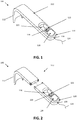
- FIG. 1 By way of illustration, embodiments of the present invention not being limited thereto, standard and optional components of the medical device are illustrated in FIG. 1 .
- the medical device 100 comprises a retractor 110.
- a retractor 110 typically may comprise a hook-shaped, angle-shaped or curved element or member 112 to be positioned around an edge of the wound or around tissue, so that using the retractor 110, once positioned accurately, a wound can be kept open and/or tissue can be positioned to make underlying body portions accessible during surgery.
- the retractor also could have a ring shaped element e.g. for positioning in an incision made in the abdomen.
- the element comprises an engaging means for engaging with the edge of the wound or the tissue.
- Such an engaging means may e.g. be a clamping element or a sticking element.
- the retractor may be provided with an element for placing at an edge of a wound or tissue.
- the retractor 110 may be made from any suitable material. While at present frequently metals, such as steel, are used, the invention is not limited thereby and the retractor can also be made of a plastic, a polymer-based material, etc. The choice of material to be used can be made such that the cost of the retractor 110 is sufficiently low that the medical device 100 can be considered as consumable. Specific examples of plastic materials that can be used are Tecanyl MT, Tecaform AH MT or Tecapro MT, but it will be clear to the skilled person that embodiments are not limited thereby.
- the retractor can have different shapes and sizes.
- retractors can be provided that are more generally applicable for different types of wounds/incisions which must be kept open.
- the retractors also may have a specific shape so that the retractor is mainly or only applicable for surgical procedures through a specific type of wound or incision.
- additional elements can be added for assisting during surgery.
- additional elements can be suction elements for keeping the wound dry or assisting thereby, lighting elements for illuminating the wound or assisting therein, etc. (not shown in FIG. 1 ).
- the medical device 100 also comprises a mechanical retracting system 120 arranged for coupling to or forming part of the retractor 110, wherein the mechanical retracting system 120 comprises a force element 126 for automatically retracting an elongate wire-like element.
- the mechanical retracting system 120 comprises a force element 126 for automatically retracting an elongate wire-like element.
- a retractor being a winding system 120 comprising a spool and force element for automatically winding an elongage wire-like element, which is a particularly advantageous embodiment, embodiments of the present invention are not limited thereto.
- the mechanical retracting system 120 may comprise an internal fixation point and an elongate wire-like element connected to the internal fixation point such as a telescopic, stretching or spring-like element, that can extend in length by providing a pulling force to it, and that automatically shortens, when no further force is applied.
- an elongate wire-like element connected to the internal fixation point such as a telescopic, stretching or spring-like element, that can extend in length by providing a pulling force to it, and that automatically shortens, when no further force is applied.
- Mechanical equivalents also allowing automatically retracting of a wire-like element are also envisaged.
- a retracting system comprising a winding system 120, whereby features and advantages can be mutates mutandis applied to mechanical retracting systems based on equivalent principles.
- a mechanical winding system 120 is embedded in the retractor 110, i.e. the retractor 110 and the mechanical winding system always form a single piece for the user.
- the mechanical winding system 120 may for example be embedded on that side of the retractor 110 that is positioned away from the hook-shaped, angle-shaped or curved element 112, i.e. that side of the retractor 110 that is furthest away from the wound.
- the mechanical winding system 120 can be hidden in the interior of the retractor 110, for example in a cavity 116. This does not only provide an aesthetic advantage, but can also ensure that the components of the mechanical winding system 120 do not become dirty or damaged during use.
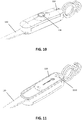
- the winding system 120 is a separate element that can be coupled to the retractor 110, e.g. as shown in FIG. 2 .
- Such connection or coupling can be done in any suitable manner, such as using a click system, using a clip connection, using a fixation system, through a glue connection or using any other connection allowing connecting the retractor to the winding system.
- this coupling or connection can be a rigid coupling, i.e. a coupling so that - e.g. after initial connection - the winding system 120 and the retractor 110 cannot undergo a substantial relative movement with respect to each other.
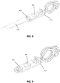
- FIG. 8 illustrates part of the winding system and part of the retractor in coupled arrangement.
- the coupling means on the retractor is a set of two holes and the coupling means on the winding system comprises a set of two protruding portions 802, 804 suitable for fitting the holes in the retractor.
- An additional clippable element can be provided for clipping the retractor and the winding system to more firmly couple to each other.
- FIG. 9 a system having a double spool for applying differential tension on the retractor is illustrated in FIG. 9 .
- the winding system is located in the immediate vicinity of the retractor 110, or even is embedded therein.
- the winding system 120 comprises at least one spool 122, which could also be referred to as a coil, for the winding of a single elongated wire-like - also referred to as wire-shaped - element.
- This elongate element can be suitable for connecting the winding system with one or more external fixation points.
- another portion of the winding system may be adapted with a connection piece for connecting to one or more external fixation points.
- a connection piece may for example be part of a hook-eye connecting element, a clickable connection, a clipable connection, a connection based on winding of an elongated element, etc.
- the elongate wire-like element 124 may be for example, a rope, a wire, a chain or a ribbon. Such an elongate wire-like element 124 may be made of a suitable material that is sufficiently strong to keep the surgical retractor 110 under tension so that during the surgery, the surgical retractor 110 is positioned and oriented in the desired direction.
- unwound elongate wire-like element 124 may be based on rotation of the spool, although other mechanical equivalents also are envisaged within the scope of the claims.
- the spool may have a shifting system for shifting components of the core of the spool. By shifting components of the core of the spool, the perimeter of the spool can be changed, e.g. enlarged, and the amount of unwound wire-like element 124 can be reduced.
- the at least one spool 122 may advantageously be incorporated in a piece of the retractor 110, or in the winding system 120.
- the at least one spool 122 may be incorporated in a housing.
- the elongated wire-like element 124 may for example be guided through one or more special openings 130 in the housing for leaving the retractor or the winding system.
- the external fixation point 150 to which the elongate wire-like element or the winding system can be connected during operation may, for example, be a point in the environment, a point on the operating table, a point on a tripod or other element that is directly or indirectly connected to or in the vicinity of the operating table, a point on the patient, etc.
- the external fixation point is a point in a surgical drape that is used during the operation, as described in a separate aspect of the present invention.
- the spool 122 comprises a force element 126 for the automatically winding of the elongated wire-like element 124 to apply or induce tension to this element.
- the force element 126 thus may be built into the spool, or may be connected to the spool 122. Alternatively the force element 126 may cooperate with the spool 122, so that a particular configuration is ensured wherein the elongate wire-like element 124 is kept under tension.
- a force element may be a torsion spring which ensures that there is an automatic mechanical winding of the elongated wire-shaped element 124, when it is not under tension.
- Alternative force elements can also be used, such as for example other types of springs, etc.
- Still another alternative force element may be a micro-electromechanical system (MEMS), such as e.g. a MEMS motor, for inducing a force on the elongate wire-like element.
- MEMS micro-electromechanical system
- the winding system also advantageously may comprise a control element 128 for activating and/or de- activating the automatically winding, i.e. for activating and/or de-activating the winding and thus inducing tension on the rope.
- a control element 128 for activating and/or de- activating the automatically winding, i.e. for activating and/or de-activating the winding and thus inducing tension on the rope.
- the control element 128 may for example be an element that controls the coupling between the force element and the spool and in this way controls the automatically winding, or may for example be an element that controls the movement of the elongate element and in this way controls the automatically winding.
- the control element 128 can be a coupling system for controlling the coupling between the spool and the force element.
- control element 128 can be a clamp for clamping the elongate element and thus blocking it.
- the control element 128 may alternatively be an additional blocking element that interferes with the spool 122 or the force element 126, and thereby prevents that automatically winding occurs.
- the control element 128 may include a manipulating point for activating and/or deactivating the automatically winding. It is an advantage of at least some embodiments of the present invention that the automatically winding can be controlled at or close to the retractor 110, so that correct positioning of the retractor 110 can be performed by the surgeon at the location where the surgical procedure is performed so that additional staff is not or nearly not required.
- control element 128 When the control element 128 has activated automatically winding, this does not only imply that automatically winding occurs of the elongated wire-like element for bringing it to tension, but it also permits the elongated wire-like element 124 for unwinding from the spool 122 when a pulling force is applied to the elongated wire-like element 124.
- the winding system 120 may comprise more than one spool 122 and more than one corresponding elongated wire-shaped element 124.
- each of the more than one spools 120 comprises a force element 126.
- These spools and/ or force elements can be positioned on top of each other or next to each other.
- One control element 128 may be provided for activating and / or deactivating some or all of the spools 122.
- the one control element 128 may control two or more spools 122 of the winding system 120 so that the elongate wire-like elements 124 can adapt to a new position or orientation of the retractor 110.
- spools 122 can be provided with a control element 128 for controlling the automatically winding of each of the spools individually. This may for example be the case for spools that are oriented in different directions outside of one and the same plane, e.g. also referred to as oriented in 3D.
- embodiments of the present invention are not limited to systems with only spools that are automatically winding, but can also contain at least some spools that are not automatically winding.
- the winding system 122 comprises two spools 120, each with an elongate wire-like element 124, a force element 126, and a control element 128.
- FIG. 3A and FIG. 3B show a schematic representation of how selecting the appropriate length of the two elongated wire-like elements 124 can determine the orientation of the retractor 110. It is clear from the drawings that a difference in length of the two elongated wire-like elements induces a different orientation of the retractor. A similar effect is obtained when more than two elongate wire-like elements 124 are used (i.e. guidance in more than two directions).
- the winding system 120 thus can be a differential winding system, whereby different spools can be used so that differential forces are induced and different positions and orientations of the retractor 110 can be obtained.
- control element can be adapted for allowing the winding system 120 to adapt to a new position by free automatically winding, when the retractor 110 is positioned in the desired position, and to subsequently limit further automatic winding of the winding system thus making sure that the desired position of the retractor is maintained.
- the control element 128 can thus be adapted such that during surgery the force mechanism can be uncoupled, can be repositioned and can again be fixed for safeguarding another position with a certain traction direction. By using different spools, different traction directions can be used for obtaining the same resulting force on the retractor 110 so that it is kept in the desired position and orientation.
- a self-retracting medical device 100 can replace the need for a medical assistant.
- the assistant needed to ensure the fixation of the retractor 110 at certain specific positions, depending on the requirements of the operation, and the assistant needed to ensure an accurate displacement and fixation this can now, by means of embodiments of the present invention, be done by the surgeon who can move the retractor 110 by hand after the activation of the winding system, and who can deactivate the winding system, once the retractor is positioned correctly.
- an accurate and easy manipulation can be obtained by manipulating the retractor 110 and by manipulating one or more control elements of the retractor 110 so that the retractor 110 can be repositioned without the need for an assistant and while no significant additional effort or loss of flexibility occurs. It is an advantage of embodiments of the present invention that there is less need for assisting personnel, which may allow more efficient surgery, as well in terms of economic cost as in terms of salary costs. Positioning of a same retractor 110 in consecutive different positions and/or with different traction directions is simple using the above device 100. In addition, the medical device 100 can reduce the required number of external fixation points without loss of stability in the traction provided.
- the system is adaptable to different surgical situations, such as for example surgery on less muscular or more muscular patients, or surgery on fatter or skinnier patients.
- the retractor needs to keep open the wound in different directions or the retractor needs to retract different tissues, which is easily possible with embodiments of the present invention.
- the number of retractors to be used can be limited and that the retractors can be manufactured in disposable material so that for example there is a reduction in sterilization and logistics costs.
- the retractor can be fixed in different traction directions in a smooth manner by a single person.
- the person handling the retractor system can first fix the retractor to different external fixation points 150 (e.g. before or at the start of the operation), and can then, during the surgical procedure, bring the retractor in the desired position or sequential desired positions by activating and deactivating the traction on the retractor itself.
- the retractor can thus be fixed in the respective orientations envisaged by the surgeon.
- the system allows that a single person can manipulate different fixation systems during a single surgery, e.g. simultaneously.
- the medical device 100 comprises an indication system for indicating the specific use of the retractor 110 during the surgical procedure.
- a retractor 110 can contain an indication system for indicating, for a set of successive steps during a surgical procedure, information about the use of the retractor 110.
- the indicator system can, for example, for each of the steps of keeping open the wound during surgery, indicate whether the retractor is to be used, in combination with which other retractor(s) the retractor is to be used, in which orientation the retractor is to be used, which external fixation points are to be used, etc.
- the indicator system may for example be based on visual, auditive or audiovisual indication. This can be done via an indication system with color code, by an indication system with a symbol code, by an indication system where the use is auditory indicated for example, via a speaker, via an indication system where the use is indicated via a display, etc.
- the different retractors that need to be used during a surgical procedure can for example have a specific color or symbol code, for example, indicated on the handle.
- the indication system can display all the steps in a single list or show the different steps successively, making it easier for the surgeon to avoid mistakes. Sequentially indicating the different steps can be done in a manual mode, whereby the surgeon in each further step wherein a different retracting of the wound is required, adjusts the indication in the indication system.
- the indication system can also be semi-automatically or automatically, wherein, e.g. on the basis of an algorithm, the next step for the wound retracting process is indicated.
- FIG. 4 illustrates an example of an indication system in the form of a summary table 410 which is indicated on a retractor 100.
- such information can be indicated on the different retractors of a set of medical retractors for performing a particular type of surgery.
- an identification 420 of the retractor itself can be indicated.
- the various retractors are in the present example, identified by a code.
- FIG. 11 another example of a medical device according to an embodiment of the present invention is shown wherein an indication system 1110 for identifying the different uses of the retractor during a surgical procedure is embedded in the device.
- the present invention also provides a medical device that does not include all of the features of the first aspect, but which is characterized by the indication system as described above.
- the present disclosure also provides a medical device that does not include all of the features of the first aspect, such as for example, does not necessarily comprise a control element, but which is characterized by the presence of a winding system with at least two spools, each of the spools being adapted for winding of an elongated wire-shaped element, wherein the spools are provided with a force element for the automatic winding of the elongated wire-shaped elements in order to bring it under tension, so that a tensile force is induced from two different directions.
- This system allows to apply a differential force on the retractor.
- Further optional components and features, as well as alternative mechanical retracting systems, can be as described in the first aspect.
- the present disclosure relates to a method for keeping open a wound during surgery.
- the method may advantageously be used when one or more medical devices are used as described in the first aspect.
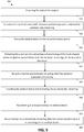
- a method according will be described with reference to FIG. 5 .
- the method 500 for keeping open a wound during surgery, as shown in FIG. 5 includes standard and optional steps.
- a first step 510 the patient is prepared for the surgical procedure.
- this step is essential for the surgical procedure itself, this step is not essential for the method for keeping open the wound, and this step can be carried out in advance. In a particular embodiment, this may be performed using a surgical drape for covering the patient.
- the surgical drape may, for example, be as described elsewhere in this description.
- a medical device comprising a retractor with winding system, e.g. as described in the first aspect, is selected.
- a medical device may take the form of an example, embodiment and/or a device according to the general principle of the first aspect. It may have or comprise a combination of elements from examples, embodiments and/or devices according to the general principles indicated of the first aspect.
- the medical device is fixed to at least one external fixation point.
- This may be to the patient, to a drape with integrated fixation points, to external objects or fixing means such as brackets or mountings, to the operation table, etc.
- Fixing the medical device typically is done by fixing one end of the elongated wire-shaped element to attach to the external fixing point. If there is initially too little elongate wire-like element available, the available wire-like element can be prolonged by activating the control element, and by making available wire-shaped element by applying a pulling force on the elongated wire-shaped element.
- the medical device comprises more than one spool, and the medical device is fixed to more than one external fixation point.
- the latter can, using embodiments of the present invention, be performed in a smooth manner.
- the method comprises the activation of the automatic winding and the positioning of the element, e.g. hook-shaped, angle-shaped or curved element, of the retractor to hold the edge of the wound or the surrounding tissue, so that the retractor is positioned in the appropriate orientation.
- the user thereby typically can grasp the medical device in the hand, control the control element so that the automatic winding is activated and the elongate wire-like elements are brought under tension by the automatic winding.
- the element e.g. hook-shaped, angle-shaped or curved element, is positioned around the edge of the wound or tissue. In this way, the medical device, more specifically, the retractor is correctly positioned.
- the method includes the deactivation of the automatic winding after the retractor is correctly positioned. In this manner, the elongate wire-like elements are fixed to the preferred length. The person handling the retractor can then put release the retractor.
- the method can comprise a sixth step 560 wherein the medical apparatus is again grasped, and the automatically winding is activated by the use of the control element.
- a seventh step the medical device 570 is then reoriented as required.
- an eighth step 580 after the correct reorientation of the medical device, the deactivation of the automatic winding takes place, and the retractor can again be released.
- an indication system can be used that provides information about the use of the one or more medical devices at a given step in the surgical process.
- Such indication can be adjusted manually or automatically, e.g. using a counter or an indication indicating the current step in the surgical process.
- the method may also comprise further optional steps, for example steps that partially or fully express the functionality of one or more elements described in the first aspect.
- the present invention also relates to a mechanical retracting system, e.g. a mechanical winding system, adapted for connecting to a medical retractor with an external fixation point for keeping open a wound or incision during surgery.
- the mechanical retracting system can be coupleable to or forming part of the medical retractor.
- the mechanical retracting system may comprises a force element for automatically retracting an elongate wire-like element to apply tension thereto.
- the mechanical retracting system may be a winding system that comprises at least one spool for winding an elongated wire-shaped element, wherein the at least one spool is provided with a force element for the automatic winding of the elongated wire-shaped element to apply tension to it.
- the mechanical retracting system advantageously is provided with at least one control element for activating / deactivating the automatic retracting.
- the mechanical retracting system e.g. winding system may further comprise one or more characteristics of the mechanical retracting system as described in embodiments of the first aspect.
- the present invention relates to a set of medical devices for keeping open a wound during surgery, wherein at least one of the medical devices is a medical device according to an embodiment of the first aspect.
- the other medical devices may for example be standard retractors.
- One of the medical devices can for example be a retractor with retracting system, e.g. winding system, whereby - in operation - the retractor and retracting system are typically configured so that the retracting system is closer to the external fixation point than to the retractor.
- the set of medical devices may also include a surgical drape, as described below. Further features and advantages of the set of medical devices may be the same or similar to those shown in the other aspects of the present description.
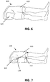
- the present disclosure relates to a surgical drape for sterile covering of the abdomen and legs for a surgical procedure.
- the surgical drape according to embodiments of this aspect can advantageously be used for hip surgery, surgery of the knees, surgery of the inguinal region, surgery of the abdomen or of the abdomen region.
- a specific example of surgery where the surgical drape can advantageously be applied is hip surgery according to the direct anterior approach (DAA), embodiments of this aspect not being limited by this.
- DAA direct anterior approach
- the surgical drape comprises a first portion provided with two legs and a second portion provided with an incision window, wherein the second portion is arranged with respect to the first portion that the incision window covers at least partly, and advantageously completely, the abdomen region and the inguinal region, when the legs - e.g. upper legs - of a patient that needs to undergo the surgery are positioned in the leg-shaped portions of the surgical drape.
- the incision window covers at least partly, and advantageously completely, the abdomen region and the inguinal region, when the legs - e.g. upper legs - of a patient that needs to undergo the surgery are positioned in the leg-shaped portions of the surgical drape.
- a surgical drape 600 is shown provided with a first part 610, which includes two leg-shaped portions. In this way, with a single cloth, both legs of the patient can be covered.
- the leg-shaped portions can be manually unrolled, e.g. once the legs have been inserted in the leg-shaped portions.
- the surgical drape 600 can be fitted with an automated system, for example provided on the inside of the leg-shaped portions, so that the cloth can be automatically unrolled.
- the leg-shaped portions can e.g. be unfold telescopically.
- the surgical drape 600 also includes a second portion 620 comprising an incision window that covers, when in position, at least part of the inguinal region and abdomen.
- the incision window can be provided in a region of the drape corresponding with the full abdomen or corresponding with both sides of the body, so that drapes are provided that can be used for different sides of the body.
- incision windows can be provided such that the same drape can be used for surgery on different parts of the body. Because this incision window is provided in the surgical drape that also allows covering the legs, the action of covering legs and providing an incision window can be completed in the same step.
- the second part which is also sometimes referred to as the upper abdomen flap, may, in some embodiments, be adapted in size so that it can further be unfolded to cover the sides of the patient and the portion up to the thorax or even further.
- openings may be provided at the side of the second portion for providing fixation elements through it.
- Such openings may for example be telescopic windows wherein the fixation elements such as rods can be inserted, the fixation elements further also being connectable to the operating table.
- the surgical drape may, in certain embodiments, also comprise a third, optional, part that sometimes is referred to as the foot flap, and that, for example, initially is attached to the rear side of the leg-shaped portions.
- This flap can be partly detached so that it can be unfold towards or over the feet.
- This part can be used as a protection layer.
- An optional fourth part of the surgical drape may be provided to the upper abdomen flap or to the foot flap, which can be unfolded to the side so that the upper abdomen flap and the foot flap may be hermetically connected to each other.
- the surgical drape therefore is a drape with four parts, i.e. a part with leg-shaped portions (also referred to as pants), an abdomen flap with an incision window at the level of the abdomen and with a telescopic side portion for the provision of external fixation elements, and a foot part to which a part is connected for hermetically connecting the abdominal portion and the foot part.
- a part with leg-shaped portions also referred to as pants
- a foot part to which a part is connected for hermetically connecting the abdominal portion and the foot part.
- the patient is entirely covered on all sides and, in addition, the legs are integrated into the fabric so that the legs can freely be moved during the surgical procedure.
- the surgical drape comprises integrated fixation points 710, as shown in FIG. 7 .
- These integrated fixation points 710 allow the surgeon or the assisting personnel to fix one or more retractors or attributes to the drape. By linking the retractors or attributes to the integrated fixation points 710 in the drape, the incision or wound can be kept open.
- the integrated fixation points 710 in the surgical drape can be position near the leg-shaped portions. This allows to couple one or more retractors to the leg-shaped portions, which retractors then can be oriented by the movement of the legs of the patient.
- both the surgical drape as well as the legs of the patient become part of or assist in the retracting system.
- the legs can be used for assisting for keeping the wound or incision open, as the legs of the patient can be moved freely and as the retractors are connected to these freely moveable legs. By moving the legs, also the retractors change their position and the wound in the patient is kept open in a specific way.
- the integration of a number of integrated fixation points 710 ensures that less handling is required to create fixation points for the retractors, but also that the retractors can easily be fixed to the surgical drape and the legs and that the surgical drape, the patient and the retractors form together a full system for keeping open wounds, e.g. a self-retracting system for keeping open wounds.
- integrated fixing points also are provided in the upper abdomen flap.
- the tensile stress caused by retractors attached to these fixation points can, for example, be compensated by coupling the upper abdomen part to fixation elements, such as rods which can be inserted through openings provided in the abdomen flap as described above.
- the retractors can also be directly attached to rods which pass through the upper abdominal flap and which are connected e.g. to the surgical table.
- an efficient system is obtained, whereby additional personnel costs can be avoided or the available personnel can be used for other actions than assisting in the wound retracting action.
- the number of retractors to be used also decreases, this also provides a possible reduction in transport costs, sterilization costs, logistics costs, etc.
- the integrated fixation points 710 in the surgical drape can be provided in such a way that relatively large forces can be tolerated.
- the latter can be obtained by integrating the fixation points at or near positions where the surgical drape is attached to an external reference point such as the leg-shaped portions that are connected to the legs of the patient or the surgical drape being fixed to external fixation elements such as support poles or tripods.
- embodiments of the present disclosure also concerns the use of a surgical drape as described above for preparing a patient for a surgical procedure.
- embodiments of the present disclosure also relate to the use of a surgical drape with an integrated fixing points for keeping open a wound during a surgical procedure.
Landscapes
- Health & Medical Sciences (AREA)
- Life Sciences & Earth Sciences (AREA)
- Surgery (AREA)
- Animal Behavior & Ethology (AREA)
- Public Health (AREA)
- Heart & Thoracic Surgery (AREA)
- Medical Informatics (AREA)
- Molecular Biology (AREA)
- Engineering & Computer Science (AREA)
- General Health & Medical Sciences (AREA)
- Biomedical Technology (AREA)
- Veterinary Medicine (AREA)
- Nuclear Medicine, Radiotherapy & Molecular Imaging (AREA)
- Physics & Mathematics (AREA)
- Biophysics (AREA)
- Optics & Photonics (AREA)
- Pathology (AREA)
- Radiology & Medical Imaging (AREA)
- Surgical Instruments (AREA)
Claims (15)
- Medizinische Vorrichtung (100) zum Offenhalten einer Wunde während einer Operation, wobei die medizinische Vorrichtung (100) umfasst- einen chirurgischen Retraktor (110), der mit einem Element (112) zum Platzieren an einem Rand einer Wunde oder eines Gewebes versehen ist,- ein mechanisches Retraktionssystem (120), dadurch gekennzeichnet, dass das mechanische Retraktionssystem (120) zum direkten Koppeln mit oder Bilden eines Teils des Retraktors (110) eingerichtet ist, wobei das mechanische Retraktionssystem (120) ein Kraftelement (126) zum automatischen Zurückziehen eines länglichen drahtartigen Elements (124) umfasst, um Spannung auf das längliche drahtartige Element (124) auszuüben.
- Medizinische Vorrichtung (100) nach Anspruch 1, wobei das mechanische Retraktionssystem (120) mit mindestens einem Steuerelement (128) zum Aktivieren und/oder Deaktivieren des automatischen Zurückziehens versehen ist.
- Medizinische Vorrichtung (100) nach einem der vorhergehenden Ansprüche, wobei das Retraktionssystem (120) ein differentielles Retraktionssystem umfasst.
- Medizinische Vorrichtung (100) nach einem der vorhergehenden Ansprüche, wobei das mechanische Retraktionssystem (120) ein mechanisches Aufwickelsystem (120) ist, wobei das mechanische Aufwickelsystem mindestens eine Spule (122) zum Aufwickeln des länglichen drahtartigen Elements (124) umfasst, wobei die mindestens eine Spule (122) mit einem Kraftelement (126) zum automatischen Aufwickeln des länglichen drahtartigen Elements versehen ist, um Spannung auf das längliche drahtartige Element (124) auszuüben, und/oder wobei das mechanische Retraktionssystem (120) ein mechanisches Aufwickelsystem (120) ist, wobei das Aufwickelsystem (120) mehr als eine Spule (122) umfasst, wobei jede Spule (122) zum Aufwickeln eines länglichen drahtartigen Elements (124) zum Verbinden des Aufwickelsystems (120) mit einem externen Fixationspunkt (150) ausgelegt ist, sodass durch die Verwendung von mehr als einer Spule (122) die Ausrichtung des Retraktors in Bezug auf die Wunde gesteuert werden kann.
- Medizinische Vorrichtung (100) nach Anspruch 4, wobei das Aufwickelsystem (120) für jede Spule (122) ein Kraftelement (126) umfasst, und/oder wobei das mindestens eine Steuerelement zum gleichzeitigen Steuern des automatischen Aufwickelns von verschiedenen Spulen eingerichtet ist, und/oder wobei das mindestens eine Steuerelement einen Satz von Steuerelementen umfasst, wobei jedes Steuerelement zum Steuern des automatischen Aufwickelns einer Spule angepasst ist.
- Medizinische Vorrichtung nach einem der vorhergehenden Ansprüche, wobei das Kraftelement (126) eine Torsionsfeder ist, oder wobei das Kraftelement ein mikroelektromechanisches System ist.
- Medizinische Vorrichtung (100) nach einem der vorhergehenden Ansprüche, soweit von Anspruch 2 abhängig, wobei das mindestens eine Steuerelement einen Steuerpunkt an dem Retraktor (110) oder an dem mechanischen Retraktionssystem (120) zum Aktivieren / Deaktivieren des automatischen Zurückziehens umfasst, und/oder wobei das Steuerelement mindestens eines aus der Gruppe aus einer Klammer zum Festklemmen des länglichen drahtartigen Elements (124), einem Blockierelement, das zum Verhindern des automatischen Aufwickelns eine Spule (122) oder das Kraftelement (126) hemmt, oder einem Kopplungsmechanismus zum lösbaren Koppeln des Kraftelements (126) und einer Spule (122) umfasst.
- Medizinische Vorrichtung (100) nach einem der vorhergehenden Ansprüche, soweit von Anspruch 4 abhängig, wobei das Aufwickelsystem (120) derart eingerichtet ist, dass, wenn es mit dem chirurgischen Retraktor gekoppelt ist, die Spule zwischen dem chirurgischen Retraktor und einem abgewickelten Abschnitt des länglichen drahtartigen Elements positioniert ist, und/oder wobei das Aufwickelsystem (120) derart eingerichtet ist, dass, wenn es mit dem chirurgischen Retraktor gekoppelt ist, ein abgewickelter Abschnitt des länglichen drahtartigen Elements zwischen dem chirurgischen Retraktor und der Spule positioniert ist.
- Medizinische Vorrichtung (100) nach einem der vorhergehenden Ansprüche, wobei das mechanische Retraktionssystem (120) und der chirurgische Retraktor (110) zwei verschiedene Elemente sind, die miteinander gekoppelt werden können und die zusammen einen Teile-Kit der medizinischen Vorrichtung (100) bilden, und/oder wobei der chirurgische Retraktor und das mechanische Retraktionssystem jedes ein Kopplungselement zum lösbaren Koppeln miteinander besitzen.
- Medizinische Vorrichtung (100) nach einem der Ansprüche 1 bis 8, wobei das mechanische Retraktionssystem (120) in den chirurgischen Retraktor (110) eingebettet ist.
- Medizinische Vorrichtung (100) nach einem der vorhergehenden Ansprüche, wobei die medizinische Vorrichtung weiter einen Anzeigemechanismus zum Anzeigen von Informationen in Hinblick auf die Verwendung des chirurgischen Retraktors (100) während eines Satzes von aufeinanderfolgenden Schritten eines operativen Eingriffs umfasst, und/oder wobei die medizinische Vorrichtung weiter einen Anzeigemechanismus zum Anzeigen von Informationen in Hinblick auf die Verwendung des chirurgischen Retraktors (100) während eines Satzes von aufeinanderfolgenden Schritten eines operativen Eingriffs umfasst, der dafür ausgelegt ist, anzuzeigen, ob bei einem bestimmten Schritt der chirurgische Retraktor zu verwenden ist, der chirurgische Retraktor in Kombination mit einem weiteren chirurgischen Retraktor zu verwenden ist, die Ausrichtung, in der der chirurgische Retraktor zu verwenden ist, und/oder welche externen Fixationspunkte (150) zu verwenden sind.
- Medizinische Vorrichtung nach einem der vorhergehenden Ansprüche, wobei das mechanische Retraktionssystem (120) mindestens eine Spule (122) zum Aufwickeln eines länglichen drahtartigen Elements (124) umfasst, das das Aufwickelsystem mit einem externen Fixationspunkt (150) verbinden kann, und/oder wobei das Element (112) zum Platzieren an einem Rand einer Wunde oder eines Gewebes ein hakenförmiges, winkelförmiges oder gekrümmtes Element zum Platzieren um den Rand einer Wunde oder eines Gewebes herum ist, oder wobei das Element ein Eingriffsmittel zum Eingriff mit dem Rand der Wunde oder des Gewebes umfasst, und/oder wobei das mechanische Retraktionssystem ein Gehäuse zum Enthalten der mindestens einen Spule umfasst, und das Gehäuse eine Öffnung (130) umfasst, durch die das längliche drahtartige Element (124) hindurchlaufen kann.
- Mechanisches Aufwickelsystem (120), das zum Verbinden eines chirurgischen Retraktors (110) mit einem externen Fixationspunkt (150) zum Offenhalten einer Wunde während einer Operation ausgelegt ist, dadurch gekennzeichnet, dass das mechanische Aufwickelsystem direkt mit dem chirurgischen Retraktor gekoppelt werden kann oder Teil des chirurgischen Retraktors bildet, wobei das Aufwickelsystem (120) mindestens eine Spule (122) zum Aufwickeln eines länglichen drahtartigen Elements (124) umfasst, und wobei die mindestens eine Spule (122) mit einem Kraftelement (126) zum automatischen Aufwickeln des länglichen drahtartigen Elements (124) versehen ist, um das längliche drahtartige Element unter Spannung zu bringen.
- Mechanisches Aufwickelsystem (120) nach Anspruch 13, wobei das mechanische Aufwickelsystem (120) mit mindestens einem Steuerelement (128) zum Aktivieren und/oder Deaktivieren des automatischen Aufwickelns versehen ist.
- Satz von medizinischen Vorrichtung zum Offenhalten einer Wunde während einer Operation, wobei mindestens eine der medizinischen Vorrichtungen eine medizinische Vorrichtung nach einem der Ansprüche 1 bis 12 ist.
Priority Applications (2)
| Application Number | Priority Date | Filing Date | Title |
|---|---|---|---|
| EP17204095.8A EP3305208B1 (de) | 2011-12-21 | 2012-12-20 | Chirurgisches tuch |
| PL12812973T PL2793711T3 (pl) | 2011-12-21 | 2012-12-20 | Systemy retraktorów chirurgicznych |
Applications Claiming Priority (2)
| Application Number | Priority Date | Filing Date | Title |
|---|---|---|---|
| BE2011/0746A BE1020338A3 (nl) | 2011-12-21 | 2011-12-21 | Apparaat en werkwijze voor het openhouden van een wonde. |
| PCT/EP2012/076528 WO2013092938A1 (en) | 2011-12-21 | 2012-12-20 | Surgical retractor systems |
Related Child Applications (2)
| Application Number | Title | Priority Date | Filing Date |
|---|---|---|---|
| EP17204095.8A Division-Into EP3305208B1 (de) | 2011-12-21 | 2012-12-20 | Chirurgisches tuch |
| EP17204095.8A Division EP3305208B1 (de) | 2011-12-21 | 2012-12-20 | Chirurgisches tuch |
Publications (2)
| Publication Number | Publication Date |
|---|---|
| EP2793711A1 EP2793711A1 (de) | 2014-10-29 |
| EP2793711B1 true EP2793711B1 (de) | 2018-02-07 |
Family
ID=47522564
Family Applications (2)
| Application Number | Title | Priority Date | Filing Date |
|---|---|---|---|
| EP17204095.8A Active EP3305208B1 (de) | 2011-12-21 | 2012-12-20 | Chirurgisches tuch |
| EP12812973.1A Active EP2793711B1 (de) | 2011-12-21 | 2012-12-20 | Chirurgische retraktorsysteme |
Family Applications Before (1)
| Application Number | Title | Priority Date | Filing Date |
|---|---|---|---|
| EP17204095.8A Active EP3305208B1 (de) | 2011-12-21 | 2012-12-20 | Chirurgisches tuch |
Country Status (18)
| Country | Link |
|---|---|
| US (1) | US9949729B2 (de) |
| EP (2) | EP3305208B1 (de) |
| JP (2) | JP6347748B2 (de) |
| KR (1) | KR102143253B1 (de) |
| CN (1) | CN104135947B (de) |
| AU (1) | AU2012356942B2 (de) |
| BE (1) | BE1020338A3 (de) |
| BR (1) | BR112014015218B1 (de) |
| CA (1) | CA2860141C (de) |
| CL (1) | CL2014001678A1 (de) |
| DK (1) | DK2793711T3 (de) |
| ES (1) | ES2668449T3 (de) |
| MY (1) | MY180139A (de) |
| NO (1) | NO2793711T3 (de) |
| PL (1) | PL2793711T3 (de) |
| PT (1) | PT2793711T (de) |
| WO (1) | WO2013092938A1 (de) |
| ZA (1) | ZA201404530B (de) |
Families Citing this family (6)
| Publication number | Priority date | Publication date | Assignee | Title |
|---|---|---|---|---|
| DE102014209995A1 (de) * | 2014-04-10 | 2015-10-15 | Gereon Lill | Vorrichtung zur Verminderung der Retraktion einer Faszie bei geöffnetem Abdomen |
| JP7194019B2 (ja) * | 2015-10-05 | 2022-12-21 | ビーブイダブリュ ホールディング エージー | マイクロ構造表面を備える低垂直力牽引装置 |
| DE102016210574A1 (de) * | 2016-06-14 | 2017-12-14 | Fasciotens Gmbh | Vorrichtung zur Verminderung der Retraktion einer Faszie oder eines Weichteilmantels bei einem offenen Weichteildefekt |
| CN110403789A (zh) * | 2019-08-01 | 2019-11-05 | 詹玮 | 一种消化科用胃部检查装置 |
| USD912813S1 (en) * | 2019-11-05 | 2021-03-09 | H&H Medical Corporation | Tissue hook for a cricothyrotomy |
| US20230293167A1 (en) * | 2021-11-12 | 2023-09-21 | Nicholas H. Mast, M.D., Inc., A California Medical Corporation | Self-retaining bone holding devices and methods |
Family Cites Families (22)
| Publication number | Priority date | Publication date | Assignee | Title |
|---|---|---|---|---|
| US1724443A (en) * | 1928-05-24 | 1929-08-13 | Alice E Wheeler | Obstetrical sheet |
| US3693618A (en) * | 1970-07-31 | 1972-09-26 | Marilyn B Madden | Disposable unitary surgical drape |
| US4119093A (en) * | 1976-09-24 | 1978-10-10 | Goodman Floyd G | Integral patient-limb surgical drape system |
| US4349019A (en) * | 1981-07-14 | 1982-09-14 | Kimberly-Clark Corporation | Surgical leggings |
| US4730609A (en) * | 1985-02-27 | 1988-03-15 | Mcconnell Bernard E | Surgical drape with limb securing structure and method for securing a surgical site |
| US4622955A (en) * | 1985-09-05 | 1986-11-18 | Mehdi Fakhrai | Surgical retractor for dissection of internal mammary artery |
| GB8704784D0 (en) * | 1987-02-28 | 1987-04-01 | Jones D A | Surgical drape |
| US5413118A (en) * | 1990-08-20 | 1995-05-09 | Baxter International Inc. | Surgical drapes for covering appendages |
| SU1824723A1 (ru) * | 1991-04-11 | 1996-10-27 | Межотраслевой научно-технический комплекс "Микрохирургия глаза" | Векорасширитель |
| CN2230571Y (zh) * | 1995-02-23 | 1996-07-10 | 肖剑锋 | 强力机械牵引钩 |
| CN2220241Y (zh) * | 1995-04-05 | 1996-02-21 | 李泮泉 | 单向控制肋弓牵拉装置 |
| JP3141321B2 (ja) | 1996-03-25 | 2001-03-05 | 高砂医科工業株式会社 | 手術用腹壁牽引器 |
| US5938592A (en) * | 1997-01-31 | 1999-08-17 | Rultract, Inc. | Surgical support apparatus with adjustable rakes and rake plate and method of use |
| EP1104258B1 (de) | 1998-08-10 | 2006-12-06 | Coroneo, Inc. | Als retraktor einsetzbares chirurgisches nahtmaterial mit befestigungsmittel |
| NO313265B1 (no) * | 1998-10-16 | 2002-09-09 | Polar Medica As | Operasjonsutstyr og bruksfremgangsmåte |
| US20040186356A1 (en) * | 2001-08-08 | 2004-09-23 | O'malley Michael T. | Surgical retractor and tissue stabilization device |
| IL147322A0 (en) * | 2001-12-26 | 2002-08-14 | Disposable garment for chastely medical examination | |
| US20070235038A1 (en) * | 2006-04-11 | 2007-10-11 | Lone Star Medical Products, Inc. | Surgical system |
| US7691058B2 (en) * | 2006-06-15 | 2010-04-06 | Boston Scientific Scimed, Inc. | Surgical retractor device and method of use |
| US20080234551A1 (en) * | 2007-03-23 | 2008-09-25 | Ming-Tsan Lin | Gasless Laparoscopic Retractor Structure |
| CN201558133U (zh) * | 2009-12-18 | 2010-08-25 | 常州贺利氏微创医疗器械有限公司 | 手术用胸腹腔牵开器 |
| CN202161360U (zh) * | 2011-07-21 | 2012-03-14 | 中国人民解放军第三军医大学第三附属医院 | 用于隐睾术后睾丸的牵引装置 |
-
2011
- 2011-12-21 BE BE2011/0746A patent/BE1020338A3/nl active
-
2012
- 2012-12-20 ES ES12812973.1T patent/ES2668449T3/es active Active
- 2012-12-20 WO PCT/EP2012/076528 patent/WO2013092938A1/en active Application Filing
- 2012-12-20 DK DK12812973.1T patent/DK2793711T3/en active
- 2012-12-20 PL PL12812973T patent/PL2793711T3/pl unknown
- 2012-12-20 US US14/367,974 patent/US9949729B2/en active Active
- 2012-12-20 JP JP2014548044A patent/JP6347748B2/ja active Active
- 2012-12-20 CN CN201280070240.8A patent/CN104135947B/zh active Active
- 2012-12-20 KR KR1020147019862A patent/KR102143253B1/ko active IP Right Grant
- 2012-12-20 EP EP17204095.8A patent/EP3305208B1/de active Active
- 2012-12-20 BR BR112014015218-7A patent/BR112014015218B1/pt active IP Right Grant
- 2012-12-20 CA CA2860141A patent/CA2860141C/en active Active
- 2012-12-20 PT PT128129731T patent/PT2793711T/pt unknown
- 2012-12-20 NO NO12812973A patent/NO2793711T3/no unknown
- 2012-12-20 EP EP12812973.1A patent/EP2793711B1/de active Active
- 2012-12-20 AU AU2012356942A patent/AU2012356942B2/en active Active
- 2012-12-20 MY MYPI2014001624A patent/MY180139A/en unknown
-
2014
- 2014-06-20 CL CL2014001678A patent/CL2014001678A1/es unknown
- 2014-06-20 ZA ZA2014/04530A patent/ZA201404530B/en unknown
-
2018
- 2018-02-07 JP JP2018019972A patent/JP2018108386A/ja active Pending
Also Published As
| Publication number | Publication date |
|---|---|
| CA2860141C (en) | 2019-10-15 |
| US20150011836A1 (en) | 2015-01-08 |
| BR112014015218A8 (pt) | 2017-07-04 |
| PT2793711T (pt) | 2018-05-10 |
| ES2668449T3 (es) | 2018-05-18 |
| KR20140105017A (ko) | 2014-08-29 |
| JP2018108386A (ja) | 2018-07-12 |
| JP6347748B2 (ja) | 2018-06-27 |
| KR102143253B1 (ko) | 2020-08-11 |
| ZA201404530B (en) | 2015-10-28 |
| DK2793711T3 (en) | 2018-05-22 |
| MY180139A (en) | 2020-11-23 |
| AU2012356942B2 (en) | 2018-04-05 |
| JP2015503956A (ja) | 2015-02-05 |
| US9949729B2 (en) | 2018-04-24 |
| WO2013092938A1 (en) | 2013-06-27 |
| NO2793711T3 (de) | 2018-07-07 |
| CA2860141A1 (en) | 2013-06-27 |
| EP3305208B1 (de) | 2019-11-06 |
| BR112014015218A2 (pt) | 2017-06-13 |
| EP3305208A1 (de) | 2018-04-11 |
| CN104135947B (zh) | 2017-06-09 |
| NZ625914A (en) | 2016-08-26 |
| BE1020338A3 (nl) | 2013-08-06 |
| AU2012356942A1 (en) | 2014-07-03 |
| BR112014015218B1 (pt) | 2021-01-19 |
| EP2793711A1 (de) | 2014-10-29 |
| PL2793711T3 (pl) | 2018-07-31 |
| CN104135947A (zh) | 2014-11-05 |
| CL2014001678A1 (es) | 2014-12-26 |
Similar Documents
| Publication | Publication Date | Title |
|---|---|---|
| EP2793711B1 (de) | Chirurgische retraktorsysteme | |
| JP5020936B2 (ja) | 外科手術用器具システム | |
| CN102160808B (zh) | 可扩展的胸腔进入口 | |
| JP2011520481A (ja) | ヘルニア修復方法およびそのための装置 | |
| US20110184440A1 (en) | Magnetically manipulable surgical mesh and apparatus for the manipulation thereof | |
| US10349927B2 (en) | Soft retractors | |
| CN113453643A (zh) | 机器人设备的手术布单 | |
| NZ625914B2 (en) | Surgical retractor systems | |
| US20150047648A1 (en) | Sterile Drape | |
| US20200121408A1 (en) | Surgical Sheet | |
| US9457136B2 (en) | Wrap and related systems and methods |
Legal Events
| Date | Code | Title | Description |
|---|---|---|---|
| PUAI | Public reference made under article 153(3) epc to a published international application that has entered the european phase |
Free format text: ORIGINAL CODE: 0009012 |
|
| 17P | Request for examination filed |
Effective date: 20140715 |
|
| AK | Designated contracting states |
Kind code of ref document: A1 Designated state(s): AL AT BE BG CH CY CZ DE DK EE ES FI FR GB GR HR HU IE IS IT LI LT LU LV MC MK MT NL NO PL PT RO RS SE SI SK SM TR |
|
| AX | Request for extension of the european patent |
Extension state: BA ME |
|
| GRAP | Despatch of communication of intention to grant a patent |
Free format text: ORIGINAL CODE: EPIDOSNIGR1 |
|
| STAA | Information on the status of an ep patent application or granted ep patent |
Free format text: STATUS: GRANT OF PATENT IS INTENDED |
|
| INTG | Intention to grant announced |
Effective date: 20170629 |
|
| RIN1 | Information on inventor provided before grant (corrected) |
Inventor name: CORTEN, KRISTOFF Inventor name: FOULON, WOUTER Inventor name: WINNELINCKX, BASTIAAN |
|
| GRAS | Grant fee paid |
Free format text: ORIGINAL CODE: EPIDOSNIGR3 |
|
| GRAJ | Information related to disapproval of communication of intention to grant by the applicant or resumption of examination proceedings by the epo deleted |
Free format text: ORIGINAL CODE: EPIDOSDIGR1 |
|
| GRAL | Information related to payment of fee for publishing/printing deleted |
Free format text: ORIGINAL CODE: EPIDOSDIGR3 |
|
| STAA | Information on the status of an ep patent application or granted ep patent |
Free format text: STATUS: REQUEST FOR EXAMINATION WAS MADE |
|
| GRAR | Information related to intention to grant a patent recorded |
Free format text: ORIGINAL CODE: EPIDOSNIGR71 |
|
| STAA | Information on the status of an ep patent application or granted ep patent |
Free format text: STATUS: GRANT OF PATENT IS INTENDED |
|
| INTC | Intention to grant announced (deleted) | ||
| INTG | Intention to grant announced |
Effective date: 20171121 |
|
| GRAA | (expected) grant |
Free format text: ORIGINAL CODE: 0009210 |
|
| STAA | Information on the status of an ep patent application or granted ep patent |
Free format text: STATUS: THE PATENT HAS BEEN GRANTED |
|
| AK | Designated contracting states |
Kind code of ref document: B1 Designated state(s): AL AT BE BG CH CY CZ DE DK EE ES FI FR GB GR HR HU IE IS IT LI LT LU LV MC MK MT NL NO PL PT RO RS SE SI SK SM TR |
|
| AX | Request for extension of the european patent |
Extension state: BA ME |
|
| REG | Reference to a national code |
Ref country code: GB Ref legal event code: FG4D |
|
| REG | Reference to a national code |
Ref country code: AT Ref legal event code: REF Ref document number: 968481 Country of ref document: AT Kind code of ref document: T Effective date: 20180215 Ref country code: CH Ref legal event code: EP |
|
| REG | Reference to a national code |
Ref country code: IE Ref legal event code: FG4D |
|
| REG | Reference to a national code |
Ref country code: DE Ref legal event code: R096 Ref document number: 602012042684 Country of ref document: DE |
|
| REG | Reference to a national code |
Ref country code: PT Ref legal event code: SC4A Ref document number: 2793711 Country of ref document: PT Date of ref document: 20180510 Kind code of ref document: T Free format text: AVAILABILITY OF NATIONAL TRANSLATION Effective date: 20180503 |
|
| REG | Reference to a national code |
Ref country code: ES Ref legal event code: FG2A Ref document number: 2668449 Country of ref document: ES Kind code of ref document: T3 Effective date: 20180518 |
|
| REG | Reference to a national code |
Ref country code: DK Ref legal event code: T3 Effective date: 20180516 Ref country code: SE Ref legal event code: TRGR |
|
| REG | Reference to a national code |
Ref country code: NL Ref legal event code: FP |
|
| REG | Reference to a national code |
Ref country code: NO Ref legal event code: T2 Effective date: 20180207 |
|
| PG25 | Lapsed in a contracting state [announced via postgrant information from national office to epo] |
Ref country code: LT Free format text: LAPSE BECAUSE OF FAILURE TO SUBMIT A TRANSLATION OF THE DESCRIPTION OR TO PAY THE FEE WITHIN THE PRESCRIBED TIME-LIMIT Effective date: 20180207 Ref country code: CY Free format text: LAPSE BECAUSE OF FAILURE TO SUBMIT A TRANSLATION OF THE DESCRIPTION OR TO PAY THE FEE WITHIN THE PRESCRIBED TIME-LIMIT Effective date: 20180207 Ref country code: HR Free format text: LAPSE BECAUSE OF FAILURE TO SUBMIT A TRANSLATION OF THE DESCRIPTION OR TO PAY THE FEE WITHIN THE PRESCRIBED TIME-LIMIT Effective date: 20180207 |
|
| PG25 | Lapsed in a contracting state [announced via postgrant information from national office to epo] |
Ref country code: RS Free format text: LAPSE BECAUSE OF FAILURE TO SUBMIT A TRANSLATION OF THE DESCRIPTION OR TO PAY THE FEE WITHIN THE PRESCRIBED TIME-LIMIT Effective date: 20180207 Ref country code: BG Free format text: LAPSE BECAUSE OF FAILURE TO SUBMIT A TRANSLATION OF THE DESCRIPTION OR TO PAY THE FEE WITHIN THE PRESCRIBED TIME-LIMIT Effective date: 20180507 Ref country code: IS Free format text: LAPSE BECAUSE OF FAILURE TO SUBMIT A TRANSLATION OF THE DESCRIPTION OR TO PAY THE FEE WITHIN THE PRESCRIBED TIME-LIMIT Effective date: 20180607 Ref country code: LV Free format text: LAPSE BECAUSE OF FAILURE TO SUBMIT A TRANSLATION OF THE DESCRIPTION OR TO PAY THE FEE WITHIN THE PRESCRIBED TIME-LIMIT Effective date: 20180207 Ref country code: GR Free format text: LAPSE BECAUSE OF FAILURE TO SUBMIT A TRANSLATION OF THE DESCRIPTION OR TO PAY THE FEE WITHIN THE PRESCRIBED TIME-LIMIT Effective date: 20180508 |
|
| PG25 | Lapsed in a contracting state [announced via postgrant information from national office to epo] |
Ref country code: EE Free format text: LAPSE BECAUSE OF FAILURE TO SUBMIT A TRANSLATION OF THE DESCRIPTION OR TO PAY THE FEE WITHIN THE PRESCRIBED TIME-LIMIT Effective date: 20180207 Ref country code: RO Free format text: LAPSE BECAUSE OF FAILURE TO SUBMIT A TRANSLATION OF THE DESCRIPTION OR TO PAY THE FEE WITHIN THE PRESCRIBED TIME-LIMIT Effective date: 20180207 Ref country code: AL Free format text: LAPSE BECAUSE OF FAILURE TO SUBMIT A TRANSLATION OF THE DESCRIPTION OR TO PAY THE FEE WITHIN THE PRESCRIBED TIME-LIMIT Effective date: 20180207 |
|
| REG | Reference to a national code |
Ref country code: DE Ref legal event code: R097 Ref document number: 602012042684 Country of ref document: DE |
|
| PG25 | Lapsed in a contracting state [announced via postgrant information from national office to epo] |
Ref country code: CZ Free format text: LAPSE BECAUSE OF FAILURE TO SUBMIT A TRANSLATION OF THE DESCRIPTION OR TO PAY THE FEE WITHIN THE PRESCRIBED TIME-LIMIT Effective date: 20180207 Ref country code: SK Free format text: LAPSE BECAUSE OF FAILURE TO SUBMIT A TRANSLATION OF THE DESCRIPTION OR TO PAY THE FEE WITHIN THE PRESCRIBED TIME-LIMIT Effective date: 20180207 Ref country code: SM Free format text: LAPSE BECAUSE OF FAILURE TO SUBMIT A TRANSLATION OF THE DESCRIPTION OR TO PAY THE FEE WITHIN THE PRESCRIBED TIME-LIMIT Effective date: 20180207 |
|
| PLBE | No opposition filed within time limit |
Free format text: ORIGINAL CODE: 0009261 |
|
| STAA | Information on the status of an ep patent application or granted ep patent |
Free format text: STATUS: NO OPPOSITION FILED WITHIN TIME LIMIT |
|
| 26N | No opposition filed |
Effective date: 20181108 |
|
| PG25 | Lapsed in a contracting state [announced via postgrant information from national office to epo] |
Ref country code: SI Free format text: LAPSE BECAUSE OF FAILURE TO SUBMIT A TRANSLATION OF THE DESCRIPTION OR TO PAY THE FEE WITHIN THE PRESCRIBED TIME-LIMIT Effective date: 20180207 |
|
| PG25 | Lapsed in a contracting state [announced via postgrant information from national office to epo] |
Ref country code: MC Free format text: LAPSE BECAUSE OF FAILURE TO SUBMIT A TRANSLATION OF THE DESCRIPTION OR TO PAY THE FEE WITHIN THE PRESCRIBED TIME-LIMIT Effective date: 20180207 |
|
| REG | Reference to a national code |
Ref country code: AT Ref legal event code: UEP Ref document number: 968481 Country of ref document: AT Kind code of ref document: T Effective date: 20180207 |
|
| PG25 | Lapsed in a contracting state [announced via postgrant information from national office to epo] |
Ref country code: MT Free format text: LAPSE BECAUSE OF NON-PAYMENT OF DUE FEES Effective date: 20181220 |
|
| PG25 | Lapsed in a contracting state [announced via postgrant information from national office to epo] |
Ref country code: HU Free format text: LAPSE BECAUSE OF FAILURE TO SUBMIT A TRANSLATION OF THE DESCRIPTION OR TO PAY THE FEE WITHIN THE PRESCRIBED TIME-LIMIT; INVALID AB INITIO Effective date: 20121220 Ref country code: MK Free format text: LAPSE BECAUSE OF NON-PAYMENT OF DUE FEES Effective date: 20180207 |
|
| PGFP | Annual fee paid to national office [announced via postgrant information from national office to epo] |
Ref country code: ES Payment date: 20230118 Year of fee payment: 11 Ref country code: CH Payment date: 20221228 Year of fee payment: 11 |
|
| PGFP | Annual fee paid to national office [announced via postgrant information from national office to epo] |
Ref country code: NL Payment date: 20231120 Year of fee payment: 12 |
|
| PGFP | Annual fee paid to national office [announced via postgrant information from national office to epo] |
Ref country code: GB Payment date: 20231219 Year of fee payment: 12 |
|
| PGFP | Annual fee paid to national office [announced via postgrant information from national office to epo] |
Ref country code: TR Payment date: 20231201 Year of fee payment: 12 Ref country code: SE Payment date: 20231222 Year of fee payment: 12 Ref country code: PT Payment date: 20231130 Year of fee payment: 12 Ref country code: NO Payment date: 20231219 Year of fee payment: 12 Ref country code: LU Payment date: 20231226 Year of fee payment: 12 Ref country code: IT Payment date: 20231221 Year of fee payment: 12 Ref country code: IE Payment date: 20231219 Year of fee payment: 12 Ref country code: FR Payment date: 20231120 Year of fee payment: 12 Ref country code: FI Payment date: 20231228 Year of fee payment: 12 Ref country code: DK Payment date: 20231222 Year of fee payment: 12 Ref country code: AT Payment date: 20231219 Year of fee payment: 12 |
|
| PGFP | Annual fee paid to national office [announced via postgrant information from national office to epo] |
Ref country code: PL Payment date: 20231129 Year of fee payment: 12 Ref country code: BE Payment date: 20231120 Year of fee payment: 12 |
|
| PGFP | Annual fee paid to national office [announced via postgrant information from national office to epo] |
Ref country code: ES Payment date: 20240118 Year of fee payment: 12 |
|
| PGFP | Annual fee paid to national office [announced via postgrant information from national office to epo] |
Ref country code: DE Payment date: 20231227 Year of fee payment: 12 Ref country code: CH Payment date: 20240101 Year of fee payment: 12 |