EP2793080B1 - Automatic-focus projection system - Google Patents
Automatic-focus projection system Download PDFInfo
- Publication number
- EP2793080B1 EP2793080B1 EP12889181.9A EP12889181A EP2793080B1 EP 2793080 B1 EP2793080 B1 EP 2793080B1 EP 12889181 A EP12889181 A EP 12889181A EP 2793080 B1 EP2793080 B1 EP 2793080B1
- Authority
- EP
- European Patent Office
- Prior art keywords
- projection
- light
- focusing
- lens group
- infrared
- Prior art date
- Legal status (The legal status is an assumption and is not a legal conclusion. Google has not performed a legal analysis and makes no representation as to the accuracy of the status listed.)
- Not-in-force
Links
Images



Classifications
-
- H—ELECTRICITY
- H04—ELECTRIC COMMUNICATION TECHNIQUE
- H04N—PICTORIAL COMMUNICATION, e.g. TELEVISION
- H04N9/00—Details of colour television systems
- H04N9/12—Picture reproducers
- H04N9/31—Projection devices for colour picture display, e.g. using electronic spatial light modulators [ESLM]
- H04N9/3141—Constructional details thereof
- H04N9/317—Convergence or focusing systems
-
- G—PHYSICS
- G03—PHOTOGRAPHY; CINEMATOGRAPHY; ANALOGOUS TECHNIQUES USING WAVES OTHER THAN OPTICAL WAVES; ELECTROGRAPHY; HOLOGRAPHY
- G03B—APPARATUS OR ARRANGEMENTS FOR TAKING PHOTOGRAPHS OR FOR PROJECTING OR VIEWING THEM; APPARATUS OR ARRANGEMENTS EMPLOYING ANALOGOUS TECHNIQUES USING WAVES OTHER THAN OPTICAL WAVES; ACCESSORIES THEREFOR
- G03B21/00—Projectors or projection-type viewers; Accessories therefor
- G03B21/14—Details
- G03B21/53—Means for automatic focusing, e.g. to compensate thermal effects
-
- G—PHYSICS
- G02—OPTICS
- G02B—OPTICAL ELEMENTS, SYSTEMS OR APPARATUS
- G02B7/00—Mountings, adjusting means, or light-tight connections, for optical elements
- G02B7/28—Systems for automatic generation of focusing signals
- G02B7/36—Systems for automatic generation of focusing signals using image sharpness techniques, e.g. image processing techniques for generating autofocus signals
-
- G—PHYSICS
- G06—COMPUTING OR CALCULATING; COUNTING
- G06F—ELECTRIC DIGITAL DATA PROCESSING
- G06F3/00—Input arrangements for transferring data to be processed into a form capable of being handled by the computer; Output arrangements for transferring data from processing unit to output unit, e.g. interface arrangements
- G06F3/01—Input arrangements or combined input and output arrangements for interaction between user and computer
-
- H—ELECTRICITY
- H04—ELECTRIC COMMUNICATION TECHNIQUE
- H04N—PICTORIAL COMMUNICATION, e.g. TELEVISION
- H04N9/00—Details of colour television systems
- H04N9/12—Picture reproducers
- H04N9/31—Projection devices for colour picture display, e.g. using electronic spatial light modulators [ESLM]
- H04N9/3191—Testing thereof
- H04N9/3194—Testing thereof including sensor feedback
-
- G—PHYSICS
- G03—PHOTOGRAPHY; CINEMATOGRAPHY; ANALOGOUS TECHNIQUES USING WAVES OTHER THAN OPTICAL WAVES; ELECTROGRAPHY; HOLOGRAPHY
- G03B—APPARATUS OR ARRANGEMENTS FOR TAKING PHOTOGRAPHS OR FOR PROJECTING OR VIEWING THEM; APPARATUS OR ARRANGEMENTS EMPLOYING ANALOGOUS TECHNIQUES USING WAVES OTHER THAN OPTICAL WAVES; ACCESSORIES THEREFOR
- G03B21/00—Projectors or projection-type viewers; Accessories therefor
- G03B21/14—Details
- G03B21/142—Adjusting of projection optics
Definitions
- This invention refers to a projection system, and more particularly to a projection system with functions of auto-focus and infrared monitoring.
- Chinese Utility Model CN201226040Y discloses a "big-screen infrared monitor projection objective" for solving focusing problems of projection objective and infrared monitoring objective, which is provided with two focusing devices, i.e., a projection focusing device 17 and a monitoring focusing device 19.
- the projection objective and infrared monitoring objective need to be focused separately.
- Labels in Figure 1 represent as follows: single negative lens 1, single negative lens 2, single negative lens 3, single positive lens 4, light splitting prism 5, single positive lens 6, single negative lens 7, balsaming lens 8, balsaming lens 9, single positive lens 10, filter 11, single positive lens 12, single negative lens 13, single positive lens 14, balsaming lens 15, projection lens barrel 16, projection focusing hand wheel 17, flange 18, monitoring focusing hand wheel 19, monitoring lens barrel 20, flange 21, CMOS chip 22, chip fixed plate 23, field diaphragm 24.
- the projection focusing device 17 needs to be adjusted to make the projection objective to focus, that is to push "the projection lens barrel 16 and the flange 18 to move telescopically in whole", so as to focus and obtain a clear projection picture. Because the infrared monitoring objective which is mounted on the projection lens barrel 16 moves along at the same time, the focusing device 19 needs to be adjusted to make the infrared monitoring objective to focus, which makes the CMOS chips 22 collect images to meet requirements of interactive operation.
- Such type of projection system requires focusing twice, which makes inconvenient in operation; on the other hand, the projection picture is formed by visible light, users can determine whether the focusing is clear by their eyes, but the eyes of users cannot determine whether the requirements of interactive operation is met since the infrared monitoring picture is formed by invisible infrared light.
- US540093 discloses an image projection device comprising at least one display panel, a projection lens system and a focus error detection system. Since the radiation source and the radiation-sensitive detector of the focus error detection system are arranged in planes which effectively coincide with the plane of the display panel, and a focus measuring beam traverses the projection lens system twice on its path to a projection screen, an accurate and reliable focus error signal is obtained.
- JPH11119184A discloses an automatic focusing device which is similar to US 5400093 except that an infrared light source is not included.
- US2010/0310247 discloses an image pickup apparatus for a camera.
- An autofocus detecting unit that receives light reflected by a light-beam splitting mirror is arranged within the image pickup apparatus.
- JPH03146935 further discloses how to modify a camera with an autofocus detecting unit into a projection device with auto-focusing function.
- US4694151 relates to an autofocusing zoom lens, which comprises a half-mirror prism and a sensor capable of detecting light in conjunction with the half-mirror prism.
- the light reflected by the half-mirror prism can be detected to make autofocus available.
- an object of the present invention is to provide a solution to the problem of a projection system requires which needs focusing twice, and is inconvenient in operation.
- the projection module and the infrared monitoring module should satisfy the following relations: when the active area of a display chip in the projection module is larger than that of the IR monitoring picture correspondingly formed on the sensing chip by the projected picture, the magnification of the monitoring objective is larger than that of an optical system formed from the light splitting element to the display chip; when the active area of a display chip in the projection module is smaller than that of the IR monitoring picture correspondingly formed on the sensing chip by the projected picture, the magnification of the monitoring objective is smaller than that of an optical system formed from the light splitting element to the display chip; when the active area of a display chip in the projection module is equal to that of the IR monitoring picture correspondingly formed on the sensing chip by the projected picture, the magnification of the monitoring objective is equal to that of an optical system formed from the light splitting element to the display chip.
- the optical angle between the light path of IR light on the first lens surface of the first lens group, which is reflected from the projection plane and then enters the sensing chip to form the IR monitoring picture should be larger than or equal to the emergent light angle of a projection light on the first lens surface.
- the projection objective is further provided with a second lens group
- the light splitting element is arranged between the first lens group and the second lens group; both the second lens group and the light splitting element are fixed structures; the light emitted from the projection source travels through the second lens group, the light splitting element, and the first lens group in turn, and then emits out.
- the light splitting element comprises two mutually bonded right-angle prisms, a light splitting film is provided on a bonding interface of the two right-angle prisms.
- the light splitting element is a light splitting sheet.
- a light spot emitted from the infrared monitoring module should keep clear at any distance within the scope of a working distance, such that it is eligible for being a reference during focusing.
- the emergent light angle of the infrared source should be less than 2 degree.
- the infrared source further comprises a collimated laser source.
- the IR light emitted from the infrared source should falls on the edge of the projected picture preferably.
- the auto-focusing projection system has the following advantages: As the first lens group can meet the focusing requirements of both the projection objective and the infrared monitoring module, when the IR light spot emitted from the infrared source is focused clearly on the sensing chip, the projected picture is focused clearly simultaneously, that is, when the IR light spot is focused via the focusing device, the focusing of the projection picture is realized simultaneously, so as to realize auto-focusing and facilitate usage, moreover; and as the infrared monitoring module and the projection module share one set of imaging system, the induction area of the sensing chip on the infrared monitoring picture is fixed, and will not vary with the projected picture, such that an interactive algorithm does not need to be re-calibration the monitoring point position.
- an auto-focusing projection system includes a projection module, an infrared monitoring module 300, an infrared light source 400, and a focusing device.
- the infrared monitoring module 300 includes a monitoring objective, and a sensing chip 301 mounted in the monitoring objective.
- Light spot 700 emitted from the infrared source 400 should keep clear at any position within the scope of a working distance, such that it can be a reference for focusing.
- a light angle of the infrared source 400 should be less than 2 degrees.
- the infrared source 400 further includes a collimated laser source.
- the projection module further includes a projection light source 100, and a projection objective 200 connected to the projection light source 100.
- the projection objective 200 includes a housing, a first lens group 201 received in the housing, and a light splitting element 500 for reflecting infrared light and transmitting of visible light.
- the light splitting element 500 is arranged at the rear of the first lens group 201.
- the projection objective 200 includes a second lens group 202 at the rear of the light splitting element, and the light splitting element 500 is arranged between the first lens group 201 and the second lens group 202.
- the second lens group 202 and the light splitting element 500 both are fixed structures.
- Light emitted from the projection light source 100 travels through the second lens group 202, the light splitting element 500, and the first lens group 201 in turn, and then emits out.
- the IR light emitted from the infrared source 400 travels through the first lens group 201 and the light splitting element 500 in turn, and then to the infrared monitoring module 300.
- Light beams emitted out from the projection light source 100 are projected on a projection plane 600 after through the projection objective 200.
- visible light rays shown as A in Fig. 3 and 4
- the light splitting element 500 in the projection objective 200 right-to-left directly, such that the projected image of visible light rays can pass though the light splitting element 500 directly and then be projected on the projection plane 600
- the IR rays shown as B in Fig. 3 and 4
- the IR rays are reflected into the infrared monitoring module 300.
- the focusing device includes a focusing control module and a focusing motor 800.
- a sensing chip 301 and the focusing motor 800 are both electrically connected to the focusing control circuit.
- the focusing control module receives a real-time IR monitoring signal from the infrared monitoring module 300, and emits a control signal to the focusing motor 800.
- the focusing motor 800 is connected to the first lens group 201 and can drive the first lens group 201 moving forward and backward inside the housing.
- the infrared monitoring module 300 is connected to the projection objective 200, and the optical axis of the infrared monitoring module 300 is coaxial with that of the projection objective after passing through the light splitting element 500.
- the optical characteristics of the projection objective 200 and the monitoring objective can ensure that the projection objective 200 focus clearly when the first lens group 201 is driven to move forward and backward by the focusing device to make the IR monitoring picture received by the sensing chip 301 to focus clearly.
- the light path characteristics for synchronous focusing are shown as follows: when the active area of a display chip in the projection module is larger than that of the IR monitoring picture correspondingly formed on the sensing chip 301 by the projected picture, the magnification of the monitoring objective is larger than that of an optical system formed from the light splitting element 500 to the display chip; when the active area of a display chip in the projection module is smaller than that of the IR monitoring picture correspondingly formed on the sensing chip 301 by the projected picture 600, the magnification of the monitoring objective is smaller than that of an optical system formed from the light splitting element 500 to the display chip; when the active area of a display chip in the projection module is equal to that of the IR monitoring picture correspondingly formed on the sensing chip 301 by the projected picture 600, the magnification of the monitoring objective is equal to that of an optical system formed from the light splitting element 500 to the display chip.
- the projected picture is referred to a projection plane occupied by the projected image formed on the projection plane 600.
- the optical angle of the light path of IR light on the first lens surface of the first lens group should be larger than or equal to the emitting angle of a projection light at the first lens surface.
- IR light spot 700 emitted from the infrared source 400 has any bounded shape, and can fall on any sites within the monitoring scope of the infrared monitoring module 300, such as the interior of the projected picture, as shown in Figs. 6A, 6B, and 6C .
- the IR light spot 700 falls on the periphery of the projected picture 600 and is adjacent to the boundary of the projected picture, which means at the edge of the projected picture, as shown in Figs. 5A, 5B .
- the IR light spot 700 emitted from the infrared source 400 can also be projected on a site apart from the projected picture with a distance, as long as it still falls within the monitoring scope of the infrared monitoring module 300.
- the focusing control circuit thus analyzes the image in the infrared monitoring objective, and sends a signal to make the auto-focusing motor 800 to drive the first lens group 201 moving forward and backward till the infrared monitoring module 300 collects clear picture.
- the first lens group 201 can meet the focusing requirements of both the projection objective 200 and the infrared monitoring objective 300, the projected picture 600 will also become clear, such that auto-focusing is realized.
- the advantages of the present invention is that, the projected plane 600 is coincided with an IR monitoring screen, the IR light spot 700 keeps clear within the working distance of the projection objective.
- the first lens group 201 can meet the focusing requirements of both the projection objective 200 and the infrared monitoring module 300, when the IR light spot 700 is focused clearly on the sensing chip 301, the projected picture 600 is focused clearly simultaneously, so as to realize auto-focusing and facilitate usage.
- the infrared monitoring module 300 and the projection module 200 share one set of imaging system, the induction area of the projected picture 600 on the sensing chip 301 is fixed, and will not change with the projected picture 600, such that an interactive algorithm does not need to be re-calibration a monitoring point position.
- the light splitting element 500 can be a light splitting prism.
- the light splitting prism includes two right-angle prisms 501 bonding together (as shown in Fig. 3 ), and a light splitting film 502 provided on the bonding interface of the two right-angle prisms 501.
- the light splitting element 500 can also be a splitter, with a working principle the same as that of the two mutually bonded right-angle prisms 501.
- the IR light spot (or picture) of the infrared source 400 is clear at any site, if the projected picture is not focused, the IR light spot (or picture) on the projection screen collected by the infrared monitoring module is unclear, an image algorithm in the auto-focusing control circuit will analyze the image in the infrared monitoring objective, and send a signal to make the auto-focusing motor drive the first lens group to move forward and backward until the image collected by the infrared monitoring module becomes clear.
- the infrared source is fixed and the IR light spot is also fixed, whether the clear requirements are met can be determined by comparing with prestored IR light spot picture.
- the first lens group can meet the focusing requirements of both the projection objective and the infrared monitoring objective, the projected picture will also become clear, such that auto-focusing is realized.
- the focusing device includes a focusing control module and a focusing motor.
- the focusing control module receives a real-time IR monitoring signal from the infrared monitoring module 300 (an electrical signal indicated by thick lines), and emits a control signal to the focusing motor, which is connected to and driven to move forward and backward by the focused projection objective
- a real-time IR monitoring signal from the infrared monitoring module 300 (an electrical signal indicated by thick lines)
- the focusing motor drives the first lens group 201 to move forward and backward.
Landscapes
- Engineering & Computer Science (AREA)
- Physics & Mathematics (AREA)
- General Physics & Mathematics (AREA)
- Multimedia (AREA)
- Signal Processing (AREA)
- General Engineering & Computer Science (AREA)
- Theoretical Computer Science (AREA)
- Optics & Photonics (AREA)
- Computer Vision & Pattern Recognition (AREA)
- Human Computer Interaction (AREA)
- Focusing (AREA)
- Projection Apparatus (AREA)
- Automatic Focus Adjustment (AREA)
- Transforming Electric Information Into Light Information (AREA)
- Lenses (AREA)
- Lens Barrels (AREA)
Description
- This invention refers to a projection system, and more particularly to a projection system with functions of auto-focus and infrared monitoring.
- As shown in
Figure 1 , Chinese Utility ModelCN201226040Y discloses a "big-screen infrared monitor projection objective" for solving focusing problems of projection objective and infrared monitoring objective, which is provided with two focusing devices, i.e., aprojection focusing device 17 and a monitoring focusingdevice 19. Thus, in this patent, the projection objective and infrared monitoring objective need to be focused separately. - Labels in
Figure 1 represent as follows: single negative lens 1, single negative lens 2, single negative lens 3, single positive lens 4, light splitting prism 5, single positive lens 6, single negative lens 7, balsaming lens 8, balsaming lens 9, singlepositive lens 10, filter 11, single positive lens 12, single negative lens 13, single positive lens 14,balsaming lens 15,projection lens barrel 16, projection focusinghand wheel 17,flange 18, monitoring focusinghand wheel 19,monitoring lens barrel 20, flange 21, CMOS chip 22, chip fixed plate 23,field diaphragm 24. - When the projection distance changes, the
projection focusing device 17 needs to be adjusted to make the projection objective to focus, that is to push "theprojection lens barrel 16 and theflange 18 to move telescopically in whole", so as to focus and obtain a clear projection picture. Because the infrared monitoring objective which is mounted on theprojection lens barrel 16 moves along at the same time, the focusingdevice 19 needs to be adjusted to make the infrared monitoring objective to focus, which makes the CMOS chips 22 collect images to meet requirements of interactive operation. - Such type of projection system requires focusing twice, which makes inconvenient in operation; on the other hand, the projection picture is formed by visible light, users can determine whether the focusing is clear by their eyes, but the eyes of users cannot determine whether the requirements of interactive operation is met since the infrared monitoring picture is formed by invisible infrared light.
-
US540093 discloses an image projection device comprising at least one display panel, a projection lens system and a focus error detection system. Since the radiation source and the radiation-sensitive detector of the focus error detection system are arranged in planes which effectively coincide with the plane of the display panel, and a focus measuring beam traverses the projection lens system twice on its path to a projection screen, an accurate and reliable focus error signal is obtained. JPH11119184A discloses an automatic focusing device which is similar toUS 5400093 except that an infrared light source is not included. -
US2010/0310247 discloses an image pickup apparatus for a camera. An autofocus detecting unit that receives light reflected by a light-beam splitting mirror is arranged within the image pickup apparatus. JPH03146935 further discloses how to modify a camera with an autofocus detecting unit into a projection device with auto-focusing function. -
US4694151 relates to an autofocusing zoom lens, which comprises a half-mirror prism and a sensor capable of detecting light in conjunction with the half-mirror prism. The light reflected by the half-mirror prism can be detected to make autofocus available. - For the defects in the art, an object of the present invention is to provide a solution to the problem of a projection system requires which needs focusing twice, and is inconvenient in operation.
- A technical solution for solving such problem is as follows:
- An auto-focusing projection system includes a projection module and an infrared monitoring module. The projection module comprising a projection light source and a projection objective, light emitted from the projection light source travelling through a light splitting element in the projection objective, and a first lens group in turn, and then emitting out; the infrared monitoring module comprising a monitoring objective and a sensing chip, an infrared source provided on the projection module, an IR(infrared) light spots emitted from the infrared source are projected within the monitoring scope of the infrared monitoring module; the IR light of the IR light spots reflected back travelling through the first lens group, the light splitting element in turn, and then into the infrared monitoring module; a focusing device for driving the first lens group moving forward and backward, the focusing device comprising a focusing control module and a focusing motor, the focusing control module receiving a real-time IR monitoring signal from the infrared monitoring module, and emitting a control signal to the focusing motor, the focusing motor being connected to the first lens group driving the first lens group to move back and forth; the optical axis of the infrared monitoring module being coaxial with that of the projection objective after passing, from the sensing chip, through the light splitting element, the optical characteristics of the projection objective and the monitoring objective ensuing that the projection objective focus clearly when the first lens group is driven to move back and forth by the focusing device to make the IR monitoring picture received by the sensing chip to be focused clearly and to make a projected picture to be focused clearly simultaneously. The infrared light source comprises a collimated laser source and an emerging angle of less than 2 degrees, wherein the light spot keeps clear at any distance within the scope of a working distance of the projection system such that it is eligible for being a reference during focusing..
- In the present invention, the projection module and the infrared monitoring module should satisfy the following relations: when the active area of a display chip in the projection module is larger than that of the IR monitoring picture correspondingly formed on the sensing chip by the projected picture, the magnification of the monitoring objective is larger than that of an optical system formed from the light splitting element to the display chip; when the active area of a display chip in the projection module is smaller than that of the IR monitoring picture correspondingly formed on the sensing chip by the projected picture, the magnification of the monitoring objective is smaller than that of an optical system formed from the light splitting element to the display chip; when the active area of a display chip in the projection module is equal to that of the IR monitoring picture correspondingly formed on the sensing chip by the projected picture, the magnification of the monitoring objective is equal to that of an optical system formed from the light splitting element to the display chip.
- Further, the optical angle between the light path of IR light on the first lens surface of the first lens group, which is reflected from the projection plane and then enters the sensing chip to form the IR monitoring picture, should be larger than or equal to the emergent light angle of a projection light on the first lens surface.
- In the present invention, the projection objective is further provided with a second lens group, the light splitting element is arranged between the first lens group and the second lens group; both the second lens group and the light splitting element are fixed structures; the light emitted from the projection source travels through the second lens group, the light splitting element, and the first lens group in turn, and then emits out.
- In the present invention, the light splitting element comprises two mutually bonded right-angle prisms, a light splitting film is provided on a bonding interface of the two right-angle prisms. Alternatively, the light splitting element is a light splitting sheet.
- In the present invention, a light spot emitted from the infrared monitoring module should keep clear at any distance within the scope of a working distance, such that it is eligible for being a reference during focusing. In addition, the emergent light angle of the infrared source should be less than 2 degree. The infrared source further comprises a collimated laser source.
- In the present invention, the IR light emitted from the infrared source should falls on the edge of the projected picture preferably.
- The auto-focusing projection system according the present invention has the following advantages: As the first lens group can meet the focusing requirements of both the projection objective and the infrared monitoring module, when the IR light spot emitted from the infrared source is focused clearly on the sensing chip, the projected picture is focused clearly simultaneously, that is, when the IR light spot is focused via the focusing device, the focusing of the projection picture is realized simultaneously, so as to realize auto-focusing and facilitate usage, moreover; and as the infrared monitoring module and the projection module share one set of imaging system, the induction area of the sensing chip on the infrared monitoring picture is fixed, and will not vary with the projected picture, such that an interactive algorithm does not need to be re-calibration the monitoring point position.
- The present invention will be further illustrated combining with the following accompanying drawings and embodiments, in the figures:
-
FIG. 1 is a schematic view of a projection system in the art; -
FIG.2 is a schematic view of a projection system according to an embodiment of the invention; -
FIG.3 is a schematic view of a projection objective and an infrared source of the projection system shown inFigure 2 ; -
FIG.4 is a schematic view of a projection objective and an infrared source of a projection system according a second embodiment of the present invention; -
FIGs.5A and 5B show sites of the IR light spot emitted from the infrared source relative to the projection picture; -
FIGs.6A, Figure 6B and Figure 6C show IR light spots with different shapes and different sites relative to the projection picture; -
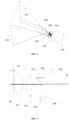
FIG.7 is a schematic diagram of focusing according an embodiment of the present invention. - Referring to
Fig. 2 , according to the first embodiment of the present invention, an auto-focusing projection system includes a projection module, aninfrared monitoring module 300, aninfrared light source 400, and a focusing device. Theinfrared monitoring module 300 includes a monitoring objective, and asensing chip 301 mounted in the monitoring objective.Light spot 700 emitted from theinfrared source 400 should keep clear at any position within the scope of a working distance, such that it can be a reference for focusing. In addition, a light angle of theinfrared source 400 should be less than 2 degrees. Theinfrared source 400 further includes a collimated laser source. - As shown in
Fig. 3 , the projection module further includes aprojection light source 100, and aprojection objective 200 connected to theprojection light source 100. Theprojection objective 200 includes a housing, afirst lens group 201 received in the housing, and alight splitting element 500 for reflecting infrared light and transmitting of visible light. Thelight splitting element 500 is arranged at the rear of thefirst lens group 201. - As shown in
Fig. 4 , in the second embodiment of the present invention, which has a working principle the same as that of the first embodiment, and different in that, theprojection objective 200 includes asecond lens group 202 at the rear of the light splitting element, and thelight splitting element 500 is arranged between thefirst lens group 201 and thesecond lens group 202. Thesecond lens group 202 and thelight splitting element 500 both are fixed structures. Light emitted from theprojection light source 100 travels through thesecond lens group 202, thelight splitting element 500, and thefirst lens group 201 in turn, and then emits out. After being reflected back, the IR light emitted from theinfrared source 400 travels through thefirst lens group 201 and thelight splitting element 500 in turn, and then to theinfrared monitoring module 300. - Light beams emitted out from the
projection light source 100 are projected on aprojection plane 600 after through theprojection objective 200. During projecting, visible light rays (shown as A inFig. 3 and4 ) can pass through thelight splitting element 500 in theprojection objective 200 right-to-left directly, such that the projected image of visible light rays can pass though thelight splitting element 500 directly and then be projected on theprojection plane 600, meanwhile, when the IR rays (shown as B inFig. 3 and4 ) on theprojection plane 600 travels through thefirst lens group 201 to thelight splitting element 500, the IR rays are reflected into theinfrared monitoring module 300. - The focusing device includes a focusing control module and a focusing
motor 800. Asensing chip 301 and the focusingmotor 800 are both electrically connected to the focusing control circuit. The focusing control module receives a real-time IR monitoring signal from theinfrared monitoring module 300, and emits a control signal to the focusingmotor 800. The focusingmotor 800 is connected to thefirst lens group 201 and can drive thefirst lens group 201 moving forward and backward inside the housing. Theinfrared monitoring module 300 is connected to theprojection objective 200, and the optical axis of theinfrared monitoring module 300 is coaxial with that of the projection objective after passing through thelight splitting element 500. In this embodiment, the optical characteristics of theprojection objective 200 and the monitoring objective can ensure that theprojection objective 200 focus clearly when thefirst lens group 201 is driven to move forward and backward by the focusing device to make the IR monitoring picture received by thesensing chip 301 to focus clearly. The light path characteristics for synchronous focusing are shown as follows: when the active area of a display chip in the projection module is larger than that of the IR monitoring picture correspondingly formed on thesensing chip 301 by the projected picture, the magnification of the monitoring objective is larger than that of an optical system formed from thelight splitting element 500 to the display chip; when the active area of a display chip in the projection module is smaller than that of the IR monitoring picture correspondingly formed on thesensing chip 301 by theprojected picture 600, the magnification of the monitoring objective is smaller than that of an optical system formed from thelight splitting element 500 to the display chip; when the active area of a display chip in the projection module is equal to that of the IR monitoring picture correspondingly formed on thesensing chip 301 by the projectedpicture 600, the magnification of the monitoring objective is equal to that of an optical system formed from thelight splitting element 500 to the display chip. Herein, the projected picture is referred to a projection plane occupied by the projected image formed on theprojection plane 600. - In the previous embodiments, in order to ensure the IR monitoring without blind spots, the optical angle of the light path of IR light on the first lens surface of the first lens group, which is reflected back from the
projection plane 600 into thesensing chip 301 and forms the IR monitoring picture, should be larger than or equal to the emitting angle of a projection light at the first lens surface. - IR
light spot 700 emitted from theinfrared source 400 has any bounded shape, and can fall on any sites within the monitoring scope of theinfrared monitoring module 300, such as the interior of the projected picture, as shown inFigs. 6A, 6B, and 6C . In order to avoid disturbing other interacting operations, in another embodiment, the IRlight spot 700 falls on the periphery of the projectedpicture 600 and is adjacent to the boundary of the projected picture, which means at the edge of the projected picture, as shown inFigs. 5A, 5B . The IRlight spot 700 emitted from theinfrared source 400 can also be projected on a site apart from the projected picture with a distance, as long as it still falls within the monitoring scope of theinfrared monitoring module 300. - Since the
light spot 700 emitted from theinfrared source 400 is clear at any site within the working distance of the projection objective, when the projectedpicture 600 doesn't focus, the picture of the IRlight spot 700 collected by theinfrared monitoring module 300 is unclear, the focusing control circuit thus analyzes the image in the infrared monitoring objective, and sends a signal to make the auto-focusingmotor 800 to drive thefirst lens group 201 moving forward and backward till theinfrared monitoring module 300 collects clear picture. As thefirst lens group 201 can meet the focusing requirements of both theprojection objective 200 and theinfrared monitoring objective 300, the projectedpicture 600 will also become clear, such that auto-focusing is realized. - The advantages of the present invention is that, the projected
plane 600 is coincided with an IR monitoring screen, the IRlight spot 700 keeps clear within the working distance of the projection objective. As thefirst lens group 201 can meet the focusing requirements of both theprojection objective 200 and theinfrared monitoring module 300, when the IRlight spot 700 is focused clearly on thesensing chip 301, the projectedpicture 600 is focused clearly simultaneously, so as to realize auto-focusing and facilitate usage. As theinfrared monitoring module 300 and theprojection module 200 share one set of imaging system, the induction area of the projectedpicture 600 on thesensing chip 301 is fixed, and will not change with the projectedpicture 600, such that an interactive algorithm does not need to be re-calibration a monitoring point position. - Preferably, the
light splitting element 500 can be a light splitting prism. Furthermore, the light splitting prism includes two right-angle prisms 501 bonding together (as shown inFig. 3 ), and alight splitting film 502 provided on the bonding interface of the two right-angle prisms 501. Thelight splitting element 500 can also be a splitter, with a working principle the same as that of the two mutually bonded right-angle prisms 501. - The working principle of the auto-focusing is shown as follows: the IR light spot (or picture) of the
infrared source 400 is clear at any site, if the projected picture is not focused, the IR light spot (or picture) on the projection screen collected by the infrared monitoring module is unclear, an image algorithm in the auto-focusing control circuit will analyze the image in the infrared monitoring objective, and send a signal to make the auto-focusing motor drive the first lens group to move forward and backward until the image collected by the infrared monitoring module becomes clear. For a particular projection system, as the infrared source is fixed and the IR light spot is also fixed, whether the clear requirements are met can be determined by comparing with prestored IR light spot picture. As the first lens group can meet the focusing requirements of both the projection objective and the infrared monitoring objective, the projected picture will also become clear, such that auto-focusing is realized. - The working principle of the auto-focusing device is shown in
Fig. 7 , the focusing device includes a focusing control module and a focusing motor. The focusing control module receives a real-time IR monitoring signal from the infrared monitoring module 300 (an electrical signal indicated by thick lines), and emits a control signal to the focusing motor, which is connected to and driven to move forward and backward by the focused projection objective The embodiment of the present invention as shown inFigs. 3 and4 , the focusing motor drives thefirst lens group 201 to move forward and backward. - It should be understood that improvement or alternations can be made according to the above mentioned descriptions for one of the ordinary skill in the art, without departing from the scope of the claims appended in the present invention.
Claims (4)
- An auto-focusing projection system comprising:a projection module comprising a projection light source (100) and a projection objective (200), light emitted from the projection light source (100) traveling through a light splitting element (500) in the projection objective (200) and a first lens group (201) in turn , and then emitting out;an infrared monitoring module (300) comprising a monitoring objective and a sensing chip (301),an infrared source (400) provided on the projection module, an IR light spot (700) emitted from the infrared source (400) falling within the monitoring scope of the infrared monitoring module (300), an IR light of the IR light spot (700) reflected back travelling through the first lens group (201), the light splitting element (500) in turn, and then into the infrared monitoring module (300);a focusing device for driving the first lens group (201) moving forward and backward, the focusing device comprising a focusing control module and a focusing motor, the focusing control module receiving a real-time IR monitoring signal from the infrared monitoring module (300), and emitting a control signal to the focusing motor, the focusing motor being connected to the first lens group (201) driving the first lens group (201) to move forward and backward;the optical axis of the infrared monitoring module (300) being coaxial with that of the projection objective (200) after passing, from the sensing chip, through the light splitting element (500),characterized in thatthe optical characteristics of the projection objective (200) and the monitoring objective ensurethat the projection objective focus clearly when the first lens group (201) is driven to move forward and backward by the focusing device to make the IR monitoring picture received by the sensing chip (301) to be focused clearly and to make the projected picture (600) to be focused clearly simultaneously;whereinthe infrared light source comprises a collimated laser source and an emerging angle of less than 2 degrees, wherein the light spot keeps clear at any distance within the scope of a working distance of the projection system such that it is eligible for being a reference during focusing.
- The auto-focusing projection system according to claim 1, wherein, the projection objective (200) comprises a second lens group (202), the light splitting element (500) is arranged between the first lens group (201) and the second lens group (202); both the second lens group (202) and the light splitting element (500) are fixed structures; the light emitted from the projection source (100) travels through the second lens group (202), the light splitting element (500), and the first lens group (201) in turn, and then emits out.
- The auto-focusing projection system according to claim 1, wherein, the optical angle of the light path of IR light on the first lens surface of the first lens group (201), which is reflected back from the projection plane (600) and enters the sensing chip (301) to form the IR monitoring picture, is larger than or equal to the emergent light angle of a projection light on the first lens surface.
- The auto-focusing projection system according to claim 1 or 2, wherein, the light splitting element (500) comprises two mutually bonded right-angle prisms (501), and a light splitting film (502) provided on a bonding interface of the two right-angle prisms (501).
Applications Claiming Priority (2)
| Application Number | Priority Date | Filing Date | Title |
|---|---|---|---|
| CN201220651171 | 2012-11-30 | ||
| PCT/CN2012/087569 WO2014082362A1 (en) | 2012-11-30 | 2012-12-26 | Automatic-focus projection system |
Publications (3)
| Publication Number | Publication Date |
|---|---|
| EP2793080A1 EP2793080A1 (en) | 2014-10-22 |
| EP2793080A4 EP2793080A4 (en) | 2015-05-27 |
| EP2793080B1 true EP2793080B1 (en) | 2017-09-13 |
Family
ID=48603907
Family Applications (2)
| Application Number | Title | Priority Date | Filing Date |
|---|---|---|---|
| EP12888988.8A Not-in-force EP2846187B1 (en) | 2012-11-30 | 2012-12-26 | Projection system with infrared monitoring |
| EP12889181.9A Not-in-force EP2793080B1 (en) | 2012-11-30 | 2012-12-26 | Automatic-focus projection system |
Family Applications Before (1)
| Application Number | Title | Priority Date | Filing Date |
|---|---|---|---|
| EP12888988.8A Not-in-force EP2846187B1 (en) | 2012-11-30 | 2012-12-26 | Projection system with infrared monitoring |
Country Status (4)
| Country | Link |
|---|---|
| US (2) | US9420246B2 (en) |
| EP (2) | EP2846187B1 (en) |
| CN (4) | CN203012332U (en) |
| WO (2) | WO2014082361A1 (en) |
Families Citing this family (30)
| Publication number | Priority date | Publication date | Assignee | Title |
|---|---|---|---|---|
| CN203012332U (en) * | 2012-11-30 | 2013-06-19 | 神画科技(深圳)有限公司 | Projection system with infrared monitor |
| WO2015013937A1 (en) * | 2013-07-31 | 2015-02-05 | 神画科技(深圳)有限公司 | Display system with interactive function |
| CN104834394B (en) * | 2014-02-09 | 2020-07-31 | 神画科技(深圳)有限公司 | an interactive display system |
| EP3147766A4 (en) * | 2014-05-23 | 2018-03-21 | Cinepic Technology (Shenzhen) Limited | Interactive display system |
| CN105549176A (en) * | 2014-10-31 | 2016-05-04 | 高准精密工业股份有限公司 | Combined optical lens and optical image device with the combined optical lens |
| WO2016095235A1 (en) * | 2014-12-19 | 2016-06-23 | 神画科技(深圳)有限公司 | Automatic focusing method for projector |
| WO2016119122A1 (en) * | 2015-01-27 | 2016-08-04 | 神画科技(深圳)有限公司 | Automatic focusing method for projector based on sensor |
| CN106371273B (en) * | 2015-07-20 | 2020-05-29 | 深圳光峰科技股份有限公司 | Mixed light source device, light-emitting control method thereof and projection system |
| CN106371274B (en) * | 2015-07-20 | 2019-11-26 | 深圳光峰科技股份有限公司 | A kind of hybrid light source device and its light-emitting control method, optical projection system |
| WO2017079964A1 (en) * | 2015-11-13 | 2017-05-18 | 神画科技(深圳)有限公司 | Method and system for automatic focusing on multi-point reference image recognition |
| CN106842472A (en) * | 2017-01-12 | 2017-06-13 | 哈尔滨工业大学 | A kind of method of transmitting/receiving light path focusing |
| WO2018214153A1 (en) * | 2017-05-26 | 2018-11-29 | 神画科技(深圳)有限公司 | Automated compensation system and method for heat-caused defocusing |
| CN107155097A (en) * | 2017-06-15 | 2017-09-12 | 上海青橙实业有限公司 | Focus adjustment method, focus control and the projection terminal of projection terminal |
| CN109426060A (en) * | 2017-08-21 | 2019-03-05 | 深圳光峰科技股份有限公司 | Projector automatic focusing method and projector |
| CN109634044A (en) * | 2017-10-08 | 2019-04-16 | 湖南光学传媒有限公司 | A kind of device of elevator projector auto-focusing |
| CN107632372B (en) * | 2017-10-25 | 2023-05-16 | 东莞市宇瞳光学科技股份有限公司 | Periscope type double-path fisheye panoramic system capable of focusing |
| CN108519719A (en) * | 2018-04-24 | 2018-09-11 | 红蝶科技(深圳)有限公司 | An intelligent projection device |
| CN108556741A (en) * | 2018-05-16 | 2018-09-21 | 英锐科技(深圳)有限公司 | The multi-functional projection of one kind showing onboard system and automobile |
| US11947038B2 (en) | 2018-12-21 | 2024-04-02 | Continental Automotive Systems, Inc. | Wavelength adaptive narrow band optical filter for a LIDAR system |
| CN111479099A (en) | 2019-01-24 | 2020-07-31 | 中强光电股份有限公司 | Projection device and projection method thereof |
| CN110418122A (en) * | 2019-07-25 | 2019-11-05 | 上海易视计算机科技股份有限公司 | A kind of control method, device, equipment and the storage medium of touch projection instrument |
| CN110505407B (en) * | 2019-09-04 | 2021-02-12 | 烟台艾睿光电科技有限公司 | Lens focusing method, device and device for infrared imaging equipment |
| US11624836B2 (en) | 2019-09-24 | 2023-04-11 | Continental Autonomous Mobility US, LLC | Detection of damage to optical element of illumination system |
| CN111050151B (en) * | 2019-12-26 | 2021-08-17 | 成都极米科技股份有限公司 | Projection focusing method, device, projector and readable storage medium |
| CN111464091B (en) * | 2020-04-08 | 2021-12-03 | 成都极米科技股份有限公司 | Control method and control device of shift motor and projection system |
| US11579265B2 (en) | 2020-08-19 | 2023-02-14 | Continental Autonomous Mobility US, LLC | Lidar system with crosstalk reduction comprising a power supply circuit layer stacked between an avalanche-type diode layer and a read-out circuit layer |
| CN113900346B (en) * | 2021-08-30 | 2023-08-29 | 安克创新科技股份有限公司 | Automatic focusing method of projector and projector |
| US12638592B2 (en) | 2021-11-05 | 2026-05-26 | Aumovio Autonomous Mobility Us, Llc | LiDAR system including object movement detection |
| CN114321840B (en) * | 2021-12-31 | 2023-08-29 | 广州市浩洋电子股份有限公司 | Stage lamp optical focusing method and stage lamp optical system |
| CN115453812B (en) * | 2022-08-17 | 2025-10-03 | 漳州万利达科技有限公司 | A method for automatically adjusting focus area in a projector |
Family Cites Families (24)
| Publication number | Priority date | Publication date | Assignee | Title |
|---|---|---|---|---|
| US3635551A (en) * | 1970-05-18 | 1972-01-18 | Gaf Corp | Automatic focusing system for projectors and the like |
| JPS6119211U (en) * | 1984-07-06 | 1986-02-04 | 株式会社 コシナ | Zoom lens with auto focus |
| JPH03146935A (en) * | 1989-11-02 | 1991-06-21 | Canon Inc | projection device |
| US5537168A (en) * | 1991-04-26 | 1996-07-16 | Canon Kabushiki Kaisha | Projection optical apparatus comprising automatic adjustment unit |
| US5400093A (en) * | 1992-12-28 | 1995-03-21 | U.S. Philips Corporation | Image projection system with autofocusing |
| JPH11119184A (en) * | 1997-10-20 | 1999-04-30 | Fujitsu General Ltd | Autofocus device for LCD projector |
| TW446848B (en) * | 2000-11-29 | 2001-07-21 | Acer Comm & Amp Multimedia Inc | Projection system for automatically adjusting focal length and method thereof |
| JP3764976B2 (en) * | 2003-10-10 | 2006-04-12 | カシオ計算機株式会社 | Projection device with photographing function and projection image photographing system |
| US7525538B2 (en) * | 2005-06-28 | 2009-04-28 | Microsoft Corporation | Using same optics to image, illuminate, and project |
| WO2008082703A2 (en) * | 2006-07-31 | 2008-07-10 | 3M Innovative Properties Company | Combination camera/projector system |
| CN201063071Y (en) * | 2007-03-06 | 2008-05-21 | 利达光电股份有限公司 | Continuously zooming projection objective |
| CN201226040Y (en) | 2008-06-20 | 2009-04-22 | 利达光电股份有限公司 | Large-screen infrared monitoring projection objective |
| US8690340B2 (en) * | 2008-12-12 | 2014-04-08 | Texas Instruments Incorporated | Combined image projection and capture system using on and off state positions of spatial light modulator |
| JP2010134051A (en) * | 2008-12-02 | 2010-06-17 | Brother Ind Ltd | Image display apparatus |
| JP5343716B2 (en) * | 2009-06-08 | 2013-11-13 | ソニー株式会社 | Imaging device |
| JP2011232474A (en) * | 2010-04-27 | 2011-11-17 | Fujifilm Corp | Projector |
| CN201749281U (en) * | 2010-06-02 | 2011-02-16 | 广景科技有限公司 | A portable interactive projection device |
| CN201804195U (en) * | 2010-09-21 | 2011-04-20 | 程抒一 | Rear protection display system capable of generating touch screen on projection screen |
| CN102591121A (en) * | 2012-02-21 | 2012-07-18 | 苏州佳世达光电有限公司 | Automatic focusing method of projector and projection system using automatic focusing method |
| CN202486394U (en) * | 2012-03-15 | 2012-10-10 | 利达光电股份有限公司 | Adjusting mechanism of zooming projection lens |
| CN202522837U (en) * | 2012-03-30 | 2012-11-07 | 日立数字映像(中国)有限公司 | Automatic focusing and automatic keystone correction device of projector |
| CN203012332U (en) * | 2012-11-30 | 2013-06-19 | 神画科技(深圳)有限公司 | Projection system with infrared monitor |
| US9891440B2 (en) * | 2012-12-31 | 2018-02-13 | Piqs Technology (Shenzhen) Limited | Infrared interactive remote control device and projection system using same |
| US20160021351A1 (en) * | 2013-03-14 | 2016-01-21 | Nittoh Kogaku K.K. | Optical system and device having optical system |
-
2012
- 2012-12-26 CN CN2012207291324U patent/CN203012332U/en not_active Expired - Lifetime
- 2012-12-26 WO PCT/CN2012/087548 patent/WO2014082361A1/en not_active Ceased
- 2012-12-26 CN CN201220730223XU patent/CN203012335U/en not_active Expired - Lifetime
- 2012-12-26 CN CN201280004100.0A patent/CN104024935B/en not_active Expired - Fee Related
- 2012-12-26 CN CN201280018064.3A patent/CN103596639B/en not_active Expired - Fee Related
- 2012-12-26 US US14/408,293 patent/US9420246B2/en not_active Expired - Fee Related
- 2012-12-26 EP EP12888988.8A patent/EP2846187B1/en not_active Not-in-force
- 2012-12-26 US US14/375,793 patent/US9420245B2/en not_active Expired - Fee Related
- 2012-12-26 WO PCT/CN2012/087569 patent/WO2014082362A1/en not_active Ceased
- 2012-12-26 EP EP12889181.9A patent/EP2793080B1/en not_active Not-in-force
Non-Patent Citations (1)
| Title |
|---|
| None * |
Also Published As
| Publication number | Publication date |
|---|---|
| CN103596639A (en) | 2014-02-19 |
| CN103596639B (en) | 2016-05-25 |
| CN203012335U (en) | 2013-06-19 |
| EP2793080A1 (en) | 2014-10-22 |
| US20150015854A1 (en) | 2015-01-15 |
| CN104024935B (en) | 2015-12-09 |
| EP2846187A1 (en) | 2015-03-11 |
| CN203012332U (en) | 2013-06-19 |
| US20150109589A1 (en) | 2015-04-23 |
| EP2846187A4 (en) | 2015-05-27 |
| US9420246B2 (en) | 2016-08-16 |
| EP2793080A4 (en) | 2015-05-27 |
| US9420245B2 (en) | 2016-08-16 |
| CN104024935A (en) | 2014-09-03 |
| EP2846187B1 (en) | 2018-11-14 |
| WO2014082361A1 (en) | 2014-06-05 |
| WO2014082362A1 (en) | 2014-06-05 |
Similar Documents
| Publication | Publication Date | Title |
|---|---|---|
| US9420245B2 (en) | Auto-focusing projection system | |
| JP6242411B2 (en) | Coordinate measuring apparatus and method of operating coordinate measuring apparatus | |
| CN103975250B (en) | The spatial selectivity utilizing dynamic mask in the plane of delineation detects | |
| US8077200B2 (en) | Image capture system and method of capturing labeled image | |
| JP5971053B2 (en) | Position detection device and image display device | |
| CN105143974B (en) | Infrared interactive remote control unit and use the optical projection system of this device | |
| CN104834394B (en) | an interactive display system | |
| KR101691156B1 (en) | Optical system having integrated illumination and imaging systems and 3D image acquisition apparatus including the optical system | |
| JPH09305312A (en) | Projection display device | |
| JP2935805B2 (en) | Auto focus projector | |
| US6501540B2 (en) | Surveying instrument having an optical distance meter | |
| US6677568B2 (en) | Surveying instrument having a phase-difference detection type focus detecting device | |
| US4389107A (en) | Focusing device for cameras | |
| CN203242154U (en) | Infrared interactive remote control device and projection system using same | |
| JP2593726Y2 (en) | Displacement detector | |
| JPS58174808A (en) | distance measuring device | |
| JPH0685015B2 (en) | Focus setting device for endoscope | |
| JPH01217425A (en) | Camera with active type range finding device | |
| KR20210016241A (en) | Optical device | |
| JP2001004908A (en) | camera | |
| JPS63235907A (en) | focus detection device | |
| JPH02264212A (en) | Automatic focus adjusting device | |
| JP2016192799A (en) | Position detection device and image display device | |
| JPH0315437A (en) | fundus camera | |
| JPS61112112A (en) | Automatic focusing device |
Legal Events
| Date | Code | Title | Description |
|---|---|---|---|
| PUAI | Public reference made under article 153(3) epc to a published international application that has entered the european phase |
Free format text: ORIGINAL CODE: 0009012 |
|
| 17P | Request for examination filed |
Effective date: 20140714 |
|
| AK | Designated contracting states |
Kind code of ref document: A1 Designated state(s): AL AT BE BG CH CY CZ DE DK EE ES FI FR GB GR HR HU IE IS IT LI LT LU LV MC MK MT NL NO PL PT RO RS SE SI SK SM TR |
|
| RAP1 | Party data changed (applicant data changed or rights of an application transferred) |
Owner name: EVIEO TECHNOLOGY (SHENZHEN) LIMITED |
|
| RA4 | Supplementary search report drawn up and despatched (corrected) |
Effective date: 20150429 |
|
| RIC1 | Information provided on ipc code assigned before grant |
Ipc: G03B 21/53 20060101AFI20150422BHEP Ipc: G02B 7/36 20060101ALI20150422BHEP |
|
| DAX | Request for extension of the european patent (deleted) | ||
| 17Q | First examination report despatched |
Effective date: 20160311 |
|
| GRAP | Despatch of communication of intention to grant a patent |
Free format text: ORIGINAL CODE: EPIDOSNIGR1 |
|
| RIC1 | Information provided on ipc code assigned before grant |
Ipc: H04N 9/31 20060101ALI20160930BHEP Ipc: G02B 7/36 20060101ALI20160930BHEP Ipc: G06F 3/01 20060101ALI20160930BHEP Ipc: G03B 21/53 20060101AFI20160930BHEP |
|
| INTG | Intention to grant announced |
Effective date: 20161025 |
|
| GRAJ | Information related to disapproval of communication of intention to grant by the applicant or resumption of examination proceedings by the epo deleted |
Free format text: ORIGINAL CODE: EPIDOSDIGR1 |
|
| GRAS | Grant fee paid |
Free format text: ORIGINAL CODE: EPIDOSNIGR3 |
|
| GRAP | Despatch of communication of intention to grant a patent |
Free format text: ORIGINAL CODE: EPIDOSNIGR1 |
|
| INTC | Intention to grant announced (deleted) | ||
| INTG | Intention to grant announced |
Effective date: 20170224 |
|
| GRAA | (expected) grant |
Free format text: ORIGINAL CODE: 0009210 |
|
| AK | Designated contracting states |
Kind code of ref document: B1 Designated state(s): AL AT BE BG CH CY CZ DE DK EE ES FI FR GB GR HR HU IE IS IT LI LT LU LV MC MK MT NL NO PL PT RO RS SE SI SK SM TR |
|
| REG | Reference to a national code |
Ref country code: GB Ref legal event code: FG4D |
|
| REG | Reference to a national code |
Ref country code: CH Ref legal event code: EP |
|
| REG | Reference to a national code |
Ref country code: IE Ref legal event code: FG4D |
|
| REG | Reference to a national code |
Ref country code: AT Ref legal event code: REF Ref document number: 928738 Country of ref document: AT Kind code of ref document: T Effective date: 20171015 |
|
| REG | Reference to a national code |
Ref country code: DE Ref legal event code: R096 Ref document number: 602012037465 Country of ref document: DE |
|
| REG | Reference to a national code |
Ref country code: FR Ref legal event code: PLFP Year of fee payment: 6 |
|
| REG | Reference to a national code |
Ref country code: NL Ref legal event code: MP Effective date: 20170913 |
|
| REG | Reference to a national code |
Ref country code: LT Ref legal event code: MG4D |
|
| PG25 | Lapsed in a contracting state [announced via postgrant information from national office to epo] |
Ref country code: HR Free format text: LAPSE BECAUSE OF FAILURE TO SUBMIT A TRANSLATION OF THE DESCRIPTION OR TO PAY THE FEE WITHIN THE PRESCRIBED TIME-LIMIT Effective date: 20170913 Ref country code: NO Free format text: LAPSE BECAUSE OF FAILURE TO SUBMIT A TRANSLATION OF THE DESCRIPTION OR TO PAY THE FEE WITHIN THE PRESCRIBED TIME-LIMIT Effective date: 20171213 Ref country code: LT Free format text: LAPSE BECAUSE OF FAILURE TO SUBMIT A TRANSLATION OF THE DESCRIPTION OR TO PAY THE FEE WITHIN THE PRESCRIBED TIME-LIMIT Effective date: 20170913 Ref country code: FI Free format text: LAPSE BECAUSE OF FAILURE TO SUBMIT A TRANSLATION OF THE DESCRIPTION OR TO PAY THE FEE WITHIN THE PRESCRIBED TIME-LIMIT Effective date: 20170913 Ref country code: SE Free format text: LAPSE BECAUSE OF FAILURE TO SUBMIT A TRANSLATION OF THE DESCRIPTION OR TO PAY THE FEE WITHIN THE PRESCRIBED TIME-LIMIT Effective date: 20170913 |
|
| REG | Reference to a national code |
Ref country code: AT Ref legal event code: MK05 Ref document number: 928738 Country of ref document: AT Kind code of ref document: T Effective date: 20170913 |
|
| PG25 | Lapsed in a contracting state [announced via postgrant information from national office to epo] |
Ref country code: RS Free format text: LAPSE BECAUSE OF FAILURE TO SUBMIT A TRANSLATION OF THE DESCRIPTION OR TO PAY THE FEE WITHIN THE PRESCRIBED TIME-LIMIT Effective date: 20170913 Ref country code: BG Free format text: LAPSE BECAUSE OF FAILURE TO SUBMIT A TRANSLATION OF THE DESCRIPTION OR TO PAY THE FEE WITHIN THE PRESCRIBED TIME-LIMIT Effective date: 20171213 Ref country code: LV Free format text: LAPSE BECAUSE OF FAILURE TO SUBMIT A TRANSLATION OF THE DESCRIPTION OR TO PAY THE FEE WITHIN THE PRESCRIBED TIME-LIMIT Effective date: 20170913 Ref country code: ES Free format text: LAPSE BECAUSE OF FAILURE TO SUBMIT A TRANSLATION OF THE DESCRIPTION OR TO PAY THE FEE WITHIN THE PRESCRIBED TIME-LIMIT Effective date: 20170913 Ref country code: GR Free format text: LAPSE BECAUSE OF FAILURE TO SUBMIT A TRANSLATION OF THE DESCRIPTION OR TO PAY THE FEE WITHIN THE PRESCRIBED TIME-LIMIT Effective date: 20171214 |
|
| PG25 | Lapsed in a contracting state [announced via postgrant information from national office to epo] |
Ref country code: NL Free format text: LAPSE BECAUSE OF FAILURE TO SUBMIT A TRANSLATION OF THE DESCRIPTION OR TO PAY THE FEE WITHIN THE PRESCRIBED TIME-LIMIT Effective date: 20170913 |
|
| PG25 | Lapsed in a contracting state [announced via postgrant information from national office to epo] |
Ref country code: CZ Free format text: LAPSE BECAUSE OF FAILURE TO SUBMIT A TRANSLATION OF THE DESCRIPTION OR TO PAY THE FEE WITHIN THE PRESCRIBED TIME-LIMIT Effective date: 20170913 Ref country code: RO Free format text: LAPSE BECAUSE OF FAILURE TO SUBMIT A TRANSLATION OF THE DESCRIPTION OR TO PAY THE FEE WITHIN THE PRESCRIBED TIME-LIMIT Effective date: 20170913 Ref country code: PL Free format text: LAPSE BECAUSE OF FAILURE TO SUBMIT A TRANSLATION OF THE DESCRIPTION OR TO PAY THE FEE WITHIN THE PRESCRIBED TIME-LIMIT Effective date: 20170913 |
|
| PG25 | Lapsed in a contracting state [announced via postgrant information from national office to epo] |
Ref country code: SM Free format text: LAPSE BECAUSE OF FAILURE TO SUBMIT A TRANSLATION OF THE DESCRIPTION OR TO PAY THE FEE WITHIN THE PRESCRIBED TIME-LIMIT Effective date: 20170913 Ref country code: AT Free format text: LAPSE BECAUSE OF FAILURE TO SUBMIT A TRANSLATION OF THE DESCRIPTION OR TO PAY THE FEE WITHIN THE PRESCRIBED TIME-LIMIT Effective date: 20170913 Ref country code: IT Free format text: LAPSE BECAUSE OF FAILURE TO SUBMIT A TRANSLATION OF THE DESCRIPTION OR TO PAY THE FEE WITHIN THE PRESCRIBED TIME-LIMIT Effective date: 20170913 Ref country code: EE Free format text: LAPSE BECAUSE OF FAILURE TO SUBMIT A TRANSLATION OF THE DESCRIPTION OR TO PAY THE FEE WITHIN THE PRESCRIBED TIME-LIMIT Effective date: 20170913 Ref country code: SK Free format text: LAPSE BECAUSE OF FAILURE TO SUBMIT A TRANSLATION OF THE DESCRIPTION OR TO PAY THE FEE WITHIN THE PRESCRIBED TIME-LIMIT Effective date: 20170913 Ref country code: IS Free format text: LAPSE BECAUSE OF FAILURE TO SUBMIT A TRANSLATION OF THE DESCRIPTION OR TO PAY THE FEE WITHIN THE PRESCRIBED TIME-LIMIT Effective date: 20180113 |
|
| REG | Reference to a national code |
Ref country code: DE Ref legal event code: R097 Ref document number: 602012037465 Country of ref document: DE |
|
| PLBE | No opposition filed within time limit |
Free format text: ORIGINAL CODE: 0009261 |
|
| STAA | Information on the status of an ep patent application or granted ep patent |
Free format text: STATUS: NO OPPOSITION FILED WITHIN TIME LIMIT |
|
| PG25 | Lapsed in a contracting state [announced via postgrant information from national office to epo] |
Ref country code: DK Free format text: LAPSE BECAUSE OF FAILURE TO SUBMIT A TRANSLATION OF THE DESCRIPTION OR TO PAY THE FEE WITHIN THE PRESCRIBED TIME-LIMIT Effective date: 20170913 |
|
| REG | Reference to a national code |
Ref country code: CH Ref legal event code: PL |
|
| 26N | No opposition filed |
Effective date: 20180614 |
|
| REG | Reference to a national code |
Ref country code: IE Ref legal event code: MM4A |
|
| PG25 | Lapsed in a contracting state [announced via postgrant information from national office to epo] |
Ref country code: LU Free format text: LAPSE BECAUSE OF NON-PAYMENT OF DUE FEES Effective date: 20171226 Ref country code: MT Free format text: LAPSE BECAUSE OF NON-PAYMENT OF DUE FEES Effective date: 20171226 |
|
| REG | Reference to a national code |
Ref country code: BE Ref legal event code: MM Effective date: 20171231 |
|
| PG25 | Lapsed in a contracting state [announced via postgrant information from national office to epo] |
Ref country code: IE Free format text: LAPSE BECAUSE OF NON-PAYMENT OF DUE FEES Effective date: 20171226 |
|
| PG25 | Lapsed in a contracting state [announced via postgrant information from national office to epo] |
Ref country code: SI Free format text: LAPSE BECAUSE OF FAILURE TO SUBMIT A TRANSLATION OF THE DESCRIPTION OR TO PAY THE FEE WITHIN THE PRESCRIBED TIME-LIMIT Effective date: 20170913 Ref country code: LI Free format text: LAPSE BECAUSE OF NON-PAYMENT OF DUE FEES Effective date: 20171231 Ref country code: BE Free format text: LAPSE BECAUSE OF NON-PAYMENT OF DUE FEES Effective date: 20171231 Ref country code: CH Free format text: LAPSE BECAUSE OF NON-PAYMENT OF DUE FEES Effective date: 20171231 |
|
| PG25 | Lapsed in a contracting state [announced via postgrant information from national office to epo] |
Ref country code: MC Free format text: LAPSE BECAUSE OF FAILURE TO SUBMIT A TRANSLATION OF THE DESCRIPTION OR TO PAY THE FEE WITHIN THE PRESCRIBED TIME-LIMIT Effective date: 20170913 Ref country code: HU Free format text: LAPSE BECAUSE OF FAILURE TO SUBMIT A TRANSLATION OF THE DESCRIPTION OR TO PAY THE FEE WITHIN THE PRESCRIBED TIME-LIMIT; INVALID AB INITIO Effective date: 20121226 |
|
| PG25 | Lapsed in a contracting state [announced via postgrant information from national office to epo] |
Ref country code: CY Free format text: LAPSE BECAUSE OF FAILURE TO SUBMIT A TRANSLATION OF THE DESCRIPTION OR TO PAY THE FEE WITHIN THE PRESCRIBED TIME-LIMIT Effective date: 20170913 |
|
| PG25 | Lapsed in a contracting state [announced via postgrant information from national office to epo] |
Ref country code: MK Free format text: LAPSE BECAUSE OF FAILURE TO SUBMIT A TRANSLATION OF THE DESCRIPTION OR TO PAY THE FEE WITHIN THE PRESCRIBED TIME-LIMIT Effective date: 20170913 |
|
| PGFP | Annual fee paid to national office [announced via postgrant information from national office to epo] |
Ref country code: DE Payment date: 20191216 Year of fee payment: 8 |
|
| PGFP | Annual fee paid to national office [announced via postgrant information from national office to epo] |
Ref country code: FR Payment date: 20191231 Year of fee payment: 8 |
|
| PG25 | Lapsed in a contracting state [announced via postgrant information from national office to epo] |
Ref country code: TR Free format text: LAPSE BECAUSE OF FAILURE TO SUBMIT A TRANSLATION OF THE DESCRIPTION OR TO PAY THE FEE WITHIN THE PRESCRIBED TIME-LIMIT Effective date: 20170913 |
|
| PGFP | Annual fee paid to national office [announced via postgrant information from national office to epo] |
Ref country code: GB Payment date: 20191220 Year of fee payment: 8 |
|
| PG25 | Lapsed in a contracting state [announced via postgrant information from national office to epo] |
Ref country code: PT Free format text: LAPSE BECAUSE OF FAILURE TO SUBMIT A TRANSLATION OF THE DESCRIPTION OR TO PAY THE FEE WITHIN THE PRESCRIBED TIME-LIMIT Effective date: 20170913 |
|
| PG25 | Lapsed in a contracting state [announced via postgrant information from national office to epo] |
Ref country code: AL Free format text: LAPSE BECAUSE OF FAILURE TO SUBMIT A TRANSLATION OF THE DESCRIPTION OR TO PAY THE FEE WITHIN THE PRESCRIBED TIME-LIMIT Effective date: 20170913 |
|
| REG | Reference to a national code |
Ref country code: DE Ref legal event code: R119 Ref document number: 602012037465 Country of ref document: DE |
|
| GBPC | Gb: european patent ceased through non-payment of renewal fee |
Effective date: 20201226 |
|
| PG25 | Lapsed in a contracting state [announced via postgrant information from national office to epo] |
Ref country code: FR Free format text: LAPSE BECAUSE OF NON-PAYMENT OF DUE FEES Effective date: 20201231 |
|
| PG25 | Lapsed in a contracting state [announced via postgrant information from national office to epo] |
Ref country code: GB Free format text: LAPSE BECAUSE OF NON-PAYMENT OF DUE FEES Effective date: 20201226 Ref country code: DE Free format text: LAPSE BECAUSE OF NON-PAYMENT OF DUE FEES Effective date: 20210701 |