EP2792885A1 - Fan case - Google Patents
Fan case Download PDFInfo
- Publication number
- EP2792885A1 EP2792885A1 EP20140162817 EP14162817A EP2792885A1 EP 2792885 A1 EP2792885 A1 EP 2792885A1 EP 20140162817 EP20140162817 EP 20140162817 EP 14162817 A EP14162817 A EP 14162817A EP 2792885 A1 EP2792885 A1 EP 2792885A1
- Authority
- EP
- European Patent Office
- Prior art keywords
- cover
- opening
- impeller
- air
- mouth
- Prior art date
- Legal status (The legal status is an assumption and is not a legal conclusion. Google has not performed a legal analysis and makes no representation as to the accuracy of the status listed.)
- Granted
Links
- 230000002093 peripheral effect Effects 0.000 claims abstract description 6
- 230000008878 coupling Effects 0.000 claims description 6
- 238000010168 coupling process Methods 0.000 claims description 6
- 238000005859 coupling reaction Methods 0.000 claims description 6
- 238000010521 absorption reaction Methods 0.000 description 1
- 230000002542 deteriorative effect Effects 0.000 description 1
- 238000013021 overheating Methods 0.000 description 1
- 238000013022 venting Methods 0.000 description 1
Images


Classifications
-
- F—MECHANICAL ENGINEERING; LIGHTING; HEATING; WEAPONS; BLASTING
- F04—POSITIVE - DISPLACEMENT MACHINES FOR LIQUIDS; PUMPS FOR LIQUIDS OR ELASTIC FLUIDS
- F04D—NON-POSITIVE-DISPLACEMENT PUMPS
- F04D25/00—Pumping installations or systems
- F04D25/02—Units comprising pumps and their driving means
- F04D25/06—Units comprising pumps and their driving means the pump being electrically driven
- F04D25/0606—Units comprising pumps and their driving means the pump being electrically driven the electric motor being specially adapted for integration in the pump
- F04D25/0613—Units comprising pumps and their driving means the pump being electrically driven the electric motor being specially adapted for integration in the pump the electric motor being of the inside-out type, i.e. the rotor is arranged radially outside a central stator
-
- F—MECHANICAL ENGINEERING; LIGHTING; HEATING; WEAPONS; BLASTING
- F04—POSITIVE - DISPLACEMENT MACHINES FOR LIQUIDS; PUMPS FOR LIQUIDS OR ELASTIC FLUIDS
- F04D—NON-POSITIVE-DISPLACEMENT PUMPS
- F04D29/00—Details, component parts, or accessories
- F04D29/08—Sealings
- F04D29/16—Sealings between pressure and suction sides
- F04D29/161—Sealings between pressure and suction sides especially adapted for elastic fluid pumps
- F04D29/162—Sealings between pressure and suction sides especially adapted for elastic fluid pumps of a centrifugal flow wheel
-
- F—MECHANICAL ENGINEERING; LIGHTING; HEATING; WEAPONS; BLASTING
- F04—POSITIVE - DISPLACEMENT MACHINES FOR LIQUIDS; PUMPS FOR LIQUIDS OR ELASTIC FLUIDS
- F04D—NON-POSITIVE-DISPLACEMENT PUMPS
- F04D29/00—Details, component parts, or accessories
- F04D29/40—Casings; Connections of working fluid
- F04D29/42—Casings; Connections of working fluid for radial or helico-centrifugal pumps
- F04D29/4206—Casings; Connections of working fluid for radial or helico-centrifugal pumps especially adapted for elastic fluid pumps
- F04D29/4226—Fan casings
-
- F—MECHANICAL ENGINEERING; LIGHTING; HEATING; WEAPONS; BLASTING
- F04—POSITIVE - DISPLACEMENT MACHINES FOR LIQUIDS; PUMPS FOR LIQUIDS OR ELASTIC FLUIDS
- F04D—NON-POSITIVE-DISPLACEMENT PUMPS
- F04D29/00—Details, component parts, or accessories
- F04D29/40—Casings; Connections of working fluid
- F04D29/42—Casings; Connections of working fluid for radial or helico-centrifugal pumps
- F04D29/44—Fluid-guiding means, e.g. diffusers
- F04D29/441—Fluid-guiding means, e.g. diffusers especially adapted for elastic fluid pumps
- F04D29/444—Bladed diffusers
-
- F—MECHANICAL ENGINEERING; LIGHTING; HEATING; WEAPONS; BLASTING
- F04—POSITIVE - DISPLACEMENT MACHINES FOR LIQUIDS; PUMPS FOR LIQUIDS OR ELASTIC FLUIDS
- F04D—NON-POSITIVE-DISPLACEMENT PUMPS
- F04D29/00—Details, component parts, or accessories
- F04D29/70—Suction grids; Strainers; Dust separation; Cleaning
- F04D29/701—Suction grids; Strainers; Dust separation; Cleaning especially adapted for elastic fluid pumps
- F04D29/703—Suction grids; Strainers; Dust separation; Cleaning especially adapted for elastic fluid pumps specially for fans, e.g. fan guards
-
- F—MECHANICAL ENGINEERING; LIGHTING; HEATING; WEAPONS; BLASTING
- F05—INDEXING SCHEMES RELATING TO ENGINES OR PUMPS IN VARIOUS SUBCLASSES OF CLASSES F01-F04
- F05D—INDEXING SCHEME FOR ASPECTS RELATING TO NON-POSITIVE-DISPLACEMENT MACHINES OR ENGINES, GAS-TURBINES OR JET-PROPULSION PLANTS
- F05D2250/00—Geometry
- F05D2250/50—Inlet or outlet
- F05D2250/52—Outlet
Definitions
- the present invention relates to fans that are used to prevent the overheating of electronic apparatus such as computers or similar applications, proposing a case for said fans developed with structural features that improve air circulation, and therefore the effectiveness of the heat removal provided by fans.
- Electronic apparatus such as computers, for example, generate heat when they are operating which heat must be removed in order to prevent the functional components from deteriorating or from experiencing a service life reduction.
- Heat removal systems normally consisting of air circulation impeller fans, arranged in the electronic apparatus themselves, are incorporated to remove the heat in the electronic apparatus in order to force outside air to enter the inside of the apparatus and expel the hot air from the inside thereof.
- a fan case is proposed, the embodiment of which fan case has been determined with structural features that favor the entrance and exit of air, thus improving conditions for air circulation through the impulsion of the fan housed therein.
- This fan case object of the invention comprises a circular body with the lateral contour open between longitudinal bars having an aerodynamic section oriented with a lateral inclination with respect to the radial plane, there being arranged a cover in the front part of the body defining a grating with concentric circular ribs having a tapering varying from those closest to the center to those on the periphery, said cover determining in the peripheral contour an arched flange facing an opposing arched flange defined by the bottom of the circular body, between which flanges there is defined a mouth in relation to the opening of the lateral contour of said circular body, the walls of said mouth being a prolongation of those of a peripheral opening defined by the impeller of the fan housed in the case.
- a fan case is thus provided in which the grating defined by the front cover presents minimum resistance to the entrance of air through the absorption produced by the fan from the inside, whereas the mouth defined in relation to the opening of the circular contour favors the exit of air impelled by the fan, virtually without any head loss, the laterally inclined aerodynamic bars of the opening of the contour of the circular body also contributing to facilitate the exit of air.
- the front cover of the case furthermore forms, in relation to the rotor of the fan, a labyrinth plug-in coupling, leaving the rotor of the fan to rotate freely, but complicating the passage of air, which also prevents head losses through said coupling, in turn favoring the output of air circulation through the case by the action of the fan.
- the proposed case has very advantageous features for small fans arranged in electronic apparatus or similar applications, acquiring its own identity and preferred character with respect to conventional fans of those applications.
- Figures 4 , 5 and 6 are perspective views seen from the rear part of respective fans provided with cases made according to the object of the invention with different numbers of bars in the opening of the lateral contour of the circular body.
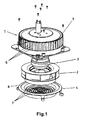
- the object of the invention relates to a fan case, particularly for fans that can be incorporated in electronic apparatus or similar applications, with a structural embodiment that advantageously favors the passage of air for the venting function, comprising a body (1), inside which there is housed an air impeller (2), associated with a rotary motor (3), whereas the front part of the case is closed with a cover (4) in the form of a grating.
- the body (1) of the case is circular-shaped and has an opening (5) along its lateral contour for the passage of air, which opening (5) is defined between longitudinal bars (6) having an aerodynamically-shaped section oriented with a lateral inclination with respect to the radial plane, the number of said bars (6) being able to vary from a large number of bars (6) with free, narrow, intermediate spaces between them, like in the embodiment of Figures 1 , 3 and 4 , to a more or less reduced number of bars (6) with free, wide, intermediate spaces between them, like in the embodiments of Figures 5 and 6 .
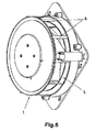
- the cover (4) of the front part of the case in turn defines a grating with concentric circular ribs (7), which have a tapering shape, said tapering varying from the ribs (7) closest to the center to those on the periphery, as can be seen in Figure 3 .
- the cover (4) furthermore determines in the peripheral contour an arched flange (8), which in the mounted arrangement of said cover (4) faces an arched flange (9) arched in an opposing manner defined by the bottom of the circular body (1) of the case, such that between said flanges (8 and 9) there is defined a mouth which widens outwardly in relation to the opening (5) of the lateral contour of said circular body (1) of the case, the walls of said mouth being defined by the mentioned flanges (8 and 9), as a prolongation of the walls (10) of an opening (11) defined by the impeller (2) of the fan in the periphery thereof.
- the entrance of the air is favored by the varying tapering configuration of the ribs (7) forming the grating of the cover (4), whereas the mouth defined by the flanges (8 and 9) favors the exit of air through the opening (5) of the lateral contour of the body (1) of the case, the aerodynamic configuration and the orientation of the bars (6) of said opening (5) of the lateral contour of the body (1) also helping to facilitate such exit of air.
- cover (4) forms with respect to the impeller (2) of the fan housed inside the case a labyrinth coupling (12), as seen in Figure 2 , which determines difficulties for the air exhaust passage between the mentioned cover (4) and the impeller (2), in turn preventing head losses through said coupling, but without complicating the functional rotation of the impeller (2), which is left to completely rotate freely.
Landscapes
- Engineering & Computer Science (AREA)
- Mechanical Engineering (AREA)
- General Engineering & Computer Science (AREA)
- Structures Of Non-Positive Displacement Pumps (AREA)
Abstract
Description
- The present invention relates to fans that are used to prevent the overheating of electronic apparatus such as computers or similar applications, proposing a case for said fans developed with structural features that improve air circulation, and therefore the effectiveness of the heat removal provided by fans.
- Electronic apparatus, such as computers, for example, generate heat when they are operating which heat must be removed in order to prevent the functional components from deteriorating or from experiencing a service life reduction.
- Heat removal systems normally consisting of air circulation impeller fans, arranged in the electronic apparatus themselves, are incorporated to remove the heat in the electronic apparatus in order to force outside air to enter the inside of the apparatus and expel the hot air from the inside thereof.
- However, the little space that is generally available in electronic apparatus means that heat removal fans arranged therein are very small, so for efficient heat removal said fans have to have certain features that maximally optimize air circulation movement.
- According to the invention a fan case is proposed, the embodiment of which fan case has been determined with structural features that favor the entrance and exit of air, thus improving conditions for air circulation through the impulsion of the fan housed therein.
- This fan case object of the invention comprises a circular body with the lateral contour open between longitudinal bars having an aerodynamic section oriented with a lateral inclination with respect to the radial plane, there being arranged a cover in the front part of the body defining a grating with concentric circular ribs having a tapering varying from those closest to the center to those on the periphery, said cover determining in the peripheral contour an arched flange facing an opposing arched flange defined by the bottom of the circular body, between which flanges there is defined a mouth in relation to the opening of the lateral contour of said circular body, the walls of said mouth being a prolongation of those of a peripheral opening defined by the impeller of the fan housed in the case.
- A fan case is thus provided in which the grating defined by the front cover presents minimum resistance to the entrance of air through the absorption produced by the fan from the inside, whereas the mouth defined in relation to the opening of the circular contour favors the exit of air impelled by the fan, virtually without any head loss, the laterally inclined aerodynamic bars of the opening of the contour of the circular body also contributing to facilitate the exit of air.
- The front cover of the case furthermore forms, in relation to the rotor of the fan, a labyrinth plug-in coupling, leaving the rotor of the fan to rotate freely, but complicating the passage of air, which also prevents head losses through said coupling, in turn favoring the output of air circulation through the case by the action of the fan.
- As a result, the proposed case has very advantageous features for small fans arranged in electronic apparatus or similar applications, acquiring its own identity and preferred character with respect to conventional fans of those applications.
-
-
Figure 1 shows an exploded perspective view of a fan provided with a case made according to the invention. -
Figure 2 is a diametral section view of the fan assembly of the preceding figure, now mounted. -
Figure 3 is a perspective view of the fan seen from the front part. -
Figures 4 ,5 and6 are perspective views seen from the rear part of respective fans provided with cases made according to the object of the invention with different numbers of bars in the opening of the lateral contour of the circular body. - The object of the invention relates to a fan case, particularly for fans that can be incorporated in electronic apparatus or similar applications, with a structural embodiment that advantageously favors the passage of air for the venting function, comprising a body (1), inside which there is housed an air impeller (2), associated with a rotary motor (3), whereas the front part of the case is closed with a cover (4) in the form of a grating.
- The body (1) of the case is circular-shaped and has an opening (5) along its lateral contour for the passage of air, which opening (5) is defined between longitudinal bars (6) having an aerodynamically-shaped section oriented with a lateral inclination with respect to the radial plane, the number of said bars (6) being able to vary from a large number of bars (6) with free, narrow, intermediate spaces between them, like in the embodiment of
Figures 1 ,3 and4 , to a more or less reduced number of bars (6) with free, wide, intermediate spaces between them, like in the embodiments ofFigures 5 and6 . - The cover (4) of the front part of the case in turn defines a grating with concentric circular ribs (7), which have a tapering shape, said tapering varying from the ribs (7) closest to the center to those on the periphery, as can be seen in
Figure 3 . - The cover (4) furthermore determines in the peripheral contour an arched flange (8), which in the mounted arrangement of said cover (4) faces an arched flange (9) arched in an opposing manner defined by the bottom of the circular body (1) of the case, such that between said flanges (8 and 9) there is defined a mouth which widens outwardly in relation to the opening (5) of the lateral contour of said circular body (1) of the case, the walls of said mouth being defined by the mentioned flanges (8 and 9), as a prolongation of the walls (10) of an opening (11) defined by the impeller (2) of the fan in the periphery thereof.
- Therefore, when the impeller (2) is rotated by the motor (3), outer air is absorbed through the front cover (4) and air inside the case is expelled through the opening (5) of the lateral contour of the body (1), giving rise to a forced air passage circulation through the case, which allows effectively removing heat from inside an electronic apparatus or any other means of application.
- For said circulation of the air through the case, the entrance of the air is favored by the varying tapering configuration of the ribs (7) forming the grating of the cover (4), whereas the mouth defined by the flanges (8 and 9) favors the exit of air through the opening (5) of the lateral contour of the body (1) of the case, the aerodynamic configuration and the orientation of the bars (6) of said opening (5) of the lateral contour of the body (1) also helping to facilitate such exit of air.
- On the other hand, the continuity of the flanges (8 and 9) forming the air outlet mouth in relation to the walls (10) of the peripheral opening (11) of the impeller (2) of the fan prevents head losses in the exit path for the air.
- Furthermore, the cover (4) forms with respect to the impeller (2) of the fan housed inside the case a labyrinth coupling (12), as seen in
Figure 2 , which determines difficulties for the air exhaust passage between the mentioned cover (4) and the impeller (2), in turn preventing head losses through said coupling, but without complicating the functional rotation of the impeller (2), which is left to completely rotate freely. - As a result, both by eliminating head losses in the entrance and exit paths for the air and because of the conditions facilitating the entrance and exit of air in the case, a very effective circulation of air is achieved with reduced power consumption of the motor (3) moving the impeller (2).
Claims (2)
- A fan case, formed by a body (1) in which there is housed an air impeller (2) associated with a motor (3), incorporating in the front part a cover (4) in the form of a grating, characterized in that the body (1) is circular-shaped and has along its lateral contour an opening (5) defined between a variable number of longitudinal bars (6) having an aerodynamic section oriented with a lateral inclination with respect to the radial plane, whereas the cover (4) defines a grating formed by concentric circular ribs (7), which have a tapering shape varying from those closest to the center to those on the periphery, said cover (4) having in the peripheral contour an arched flange (8) facing an arched flange (9) arched in an opposing manner defined by the bottom of the body (1), between which flanges (8 and 9) there is defined a mouth which widens outwardly in relation to the opening (5) of the lateral contour, whereas the walls of said mouth defined by the mentioned flanges (8 and 9) are a prolongation of the walls (10) of an opening (11) of the periphery of the impeller (2).
- The fan case according to claim 1, characterized in that the cover (4) forms in relation to the impeller (2) a labyrinth coupling (12) complicating the discharge of air through said coupling, leaving the impeller (2) to rotate freely.
Priority Applications (1)
| Application Number | Priority Date | Filing Date | Title |
|---|---|---|---|
| PL14162817T PL2792885T3 (en) | 2013-04-16 | 2014-03-31 | Fan assembly comprising a case for the impeller |
Applications Claiming Priority (1)
| Application Number | Priority Date | Filing Date | Title |
|---|---|---|---|
| ES201330543A ES2509990B1 (en) | 2013-04-16 | 2013-04-16 | FAN BOX |
Publications (2)
| Publication Number | Publication Date |
|---|---|
| EP2792885A1 true EP2792885A1 (en) | 2014-10-22 |
| EP2792885B1 EP2792885B1 (en) | 2016-08-31 |
Family
ID=50542793
Family Applications (1)
| Application Number | Title | Priority Date | Filing Date |
|---|---|---|---|
| EP14162817.2A Active EP2792885B1 (en) | 2013-04-16 | 2014-03-31 | Fan assembly comprising a case for the impeller |
Country Status (4)
| Country | Link |
|---|---|
| EP (1) | EP2792885B1 (en) |
| DK (1) | DK2792885T3 (en) |
| ES (1) | ES2509990B1 (en) |
| PL (1) | PL2792885T3 (en) |
Cited By (6)
| Publication number | Priority date | Publication date | Assignee | Title |
|---|---|---|---|---|
| DE102015207948A1 (en) * | 2015-04-29 | 2016-11-03 | Ziehl-Abegg Se | Inlet nozzle for a radial, diagonal or axial fan and radial, diagonal or axial fan with an inlet nozzle |
| DE102015207800A1 (en) | 2015-04-28 | 2016-11-03 | Ziehl-Abegg Se | Diagonal or centrifugal fan, guide for such a fan and system with such a fan or with several such fans |
| CN106647982A (en) * | 2016-10-14 | 2017-05-10 | 柳州译海网络科技有限公司 | Computer radiator |
| CN108401402A (en) * | 2018-03-30 | 2018-08-14 | 四川斐讯信息技术有限公司 | A kind of multistage air-cooled radiating device |
| DE102018202487A1 (en) | 2018-02-19 | 2019-08-22 | Ziehl-Abegg Se | Fan and method for mounting a fan |
| DE102018211808A1 (en) | 2018-07-16 | 2020-01-16 | Ziehl-Abegg Se | Fan and control device for a fan |
Citations (8)
| Publication number | Priority date | Publication date | Assignee | Title |
|---|---|---|---|---|
| DE3343078A1 (en) * | 1983-11-29 | 1985-06-05 | Walfried Dipl.-Ing. 5400 Koblenz Dost | Heaters in the form of radiators, panels and convectors |
| DE9408379U1 (en) * | 1994-05-20 | 1994-07-21 | Gebhardt Ventilatoren | Fan unit |
| WO2004068039A1 (en) * | 2003-01-29 | 2004-08-12 | Koninklijke Philips Electronics N.V. | Outlet grill for use in an air-blowing device having an axial fan |
| US20070253806A1 (en) * | 2004-01-30 | 2007-11-01 | Farmer Controls Plc | Electric Fan |
| US20100329857A1 (en) * | 2008-02-19 | 2010-12-30 | Ebm-Papst Mulfingen Gmbh & Co. Kg | Compact Fan |
| US20110150632A1 (en) * | 2009-12-22 | 2011-06-23 | Thomas Heli | Fan Unit for Filter Fans |
| EP2461042A2 (en) * | 2010-12-03 | 2012-06-06 | LG Electronics Inc. | Air blower for an air conditioner |
| US20120195747A1 (en) * | 2011-01-27 | 2012-08-02 | Minebea Co., Ltd. | Centrifugal fan |
Family Cites Families (2)
| Publication number | Priority date | Publication date | Assignee | Title |
|---|---|---|---|---|
| GB896841A (en) * | 1958-03-21 | 1962-05-16 | Norvent Ltd | Improvements in or connected with air diffusers or ventilators |
| EP2329149B1 (en) * | 2008-11-07 | 2014-05-07 | EBM-Papst Mulfingen GmbH&CO. KG | Diagonal fan |
-
2013
- 2013-04-16 ES ES201330543A patent/ES2509990B1/en active Active
-
2014
- 2014-03-31 PL PL14162817T patent/PL2792885T3/en unknown
- 2014-03-31 EP EP14162817.2A patent/EP2792885B1/en active Active
- 2014-03-31 DK DK14162817.2T patent/DK2792885T3/en active
Patent Citations (8)
| Publication number | Priority date | Publication date | Assignee | Title |
|---|---|---|---|---|
| DE3343078A1 (en) * | 1983-11-29 | 1985-06-05 | Walfried Dipl.-Ing. 5400 Koblenz Dost | Heaters in the form of radiators, panels and convectors |
| DE9408379U1 (en) * | 1994-05-20 | 1994-07-21 | Gebhardt Ventilatoren | Fan unit |
| WO2004068039A1 (en) * | 2003-01-29 | 2004-08-12 | Koninklijke Philips Electronics N.V. | Outlet grill for use in an air-blowing device having an axial fan |
| US20070253806A1 (en) * | 2004-01-30 | 2007-11-01 | Farmer Controls Plc | Electric Fan |
| US20100329857A1 (en) * | 2008-02-19 | 2010-12-30 | Ebm-Papst Mulfingen Gmbh & Co. Kg | Compact Fan |
| US20110150632A1 (en) * | 2009-12-22 | 2011-06-23 | Thomas Heli | Fan Unit for Filter Fans |
| EP2461042A2 (en) * | 2010-12-03 | 2012-06-06 | LG Electronics Inc. | Air blower for an air conditioner |
| US20120195747A1 (en) * | 2011-01-27 | 2012-08-02 | Minebea Co., Ltd. | Centrifugal fan |
Cited By (13)
| Publication number | Priority date | Publication date | Assignee | Title |
|---|---|---|---|---|
| US10724539B2 (en) | 2015-04-28 | 2020-07-28 | Ziehl-Abegg Se | Diagonal or radial fan having a guide device |
| DE102015207800A1 (en) | 2015-04-28 | 2016-11-03 | Ziehl-Abegg Se | Diagonal or centrifugal fan, guide for such a fan and system with such a fan or with several such fans |
| WO2016173594A1 (en) | 2015-04-28 | 2016-11-03 | Ziehl-Abegg Se | Diagonal or radial fan having a guide device |
| CN107532609A (en) * | 2015-04-28 | 2018-01-02 | 施乐百有限公司 | Diagonal flow type or radial fan with guider |
| CN107532609B (en) * | 2015-04-28 | 2020-12-15 | 施乐百有限公司 | Diagonal or radial fan with guide device |
| DE102015207948A1 (en) * | 2015-04-29 | 2016-11-03 | Ziehl-Abegg Se | Inlet nozzle for a radial, diagonal or axial fan and radial, diagonal or axial fan with an inlet nozzle |
| CN106647982A (en) * | 2016-10-14 | 2017-05-10 | 柳州译海网络科技有限公司 | Computer radiator |
| DE102018202487A1 (en) | 2018-02-19 | 2019-08-22 | Ziehl-Abegg Se | Fan and method for mounting a fan |
| US11067097B2 (en) | 2018-02-19 | 2021-07-20 | Ziehl-Abegg Se | Ventilator and method for mounting a ventilator |
| CN108401402A (en) * | 2018-03-30 | 2018-08-14 | 四川斐讯信息技术有限公司 | A kind of multistage air-cooled radiating device |
| DE102018211808A1 (en) | 2018-07-16 | 2020-01-16 | Ziehl-Abegg Se | Fan and control device for a fan |
| WO2020015792A1 (en) | 2018-07-16 | 2020-01-23 | Ziehl-Abegg Se | Ventilator and deflector plate for a ventilator |
| US11359644B2 (en) | 2018-07-16 | 2022-06-14 | Ziehl-Abegg Se | Ventilator and deflector plate for a ventilator |
Also Published As
| Publication number | Publication date |
|---|---|
| PL2792885T3 (en) | 2017-04-28 |
| ES2509990R1 (en) | 2014-12-30 |
| DK2792885T3 (en) | 2016-12-19 |
| ES2509990B1 (en) | 2015-07-28 |
| EP2792885B1 (en) | 2016-08-31 |
| ES2509990A2 (en) | 2014-10-20 |
Similar Documents
| Publication | Publication Date | Title |
|---|---|---|
| EP2792885B1 (en) | Fan assembly comprising a case for the impeller | |
| JP6630467B2 (en) | Fan module for heat exchanger | |
| JP4337669B2 (en) | Electric blower fan device for vehicles | |
| JP6082520B2 (en) | Impeller used for axial flow fan and axial flow fan using the same | |
| CN102968164A (en) | Cooling system with backflow prevention function | |
| CN107781215B (en) | Blade module and fan applying same | |
| JP2008163941A (en) | Assembling type impeller | |
| CN107532612B (en) | Centrifugal blower | |
| JP6636150B2 (en) | Electric blowers and vacuum cleaners | |
| JP2018503771A (en) | Fan assembly | |
| JP6436923B2 (en) | Counter-rotating fan | |
| US20140079541A1 (en) | Electronic device | |
| JP2007009803A (en) | Fan motor | |
| JP6570105B2 (en) | Fan assembly | |
| US11639726B2 (en) | Blower | |
| KR101823503B1 (en) | Axial Flow Type Blower for Air Cleaner and Blowing apparatus at Air Cleaner using the same | |
| CN114483655A (en) | Fan system and electric appliance | |
| US20210123611A1 (en) | Diffuser, diffuser assembly, and air conditioner having the same | |
| US9655278B2 (en) | Slim fan structure | |
| JP4349327B2 (en) | Whirlpool fan | |
| CN105626580B (en) | Shell for containing multi-wing centrifugal impeller of range hood, fan and range hood | |
| JP6063684B2 (en) | Axial fan | |
| KR101850287B1 (en) | Fan flow rate of correction and Low noise operation type Centrifugal impella fan | |
| CN107061357B (en) | Blade, centrifugal blower fan blade wheel, centrifugal blower and range hood | |
| JP2016160905A (en) | Centrifugal fan |
Legal Events
| Date | Code | Title | Description |
|---|---|---|---|
| PUAI | Public reference made under article 153(3) epc to a published international application that has entered the european phase |
Free format text: ORIGINAL CODE: 0009012 |
|
| 17P | Request for examination filed |
Effective date: 20140331 |
|
| AK | Designated contracting states |
Kind code of ref document: A1 Designated state(s): AL AT BE BG CH CY CZ DE DK EE ES FI FR GB GR HR HU IE IS IT LI LT LU LV MC MK MT NL NO PL PT RO RS SE SI SK SM TR |
|
| AX | Request for extension of the european patent |
Extension state: BA ME |
|
| R17P | Request for examination filed (corrected) |
Effective date: 20150417 |
|
| RBV | Designated contracting states (corrected) |
Designated state(s): AL AT BE BG CH CY CZ DE DK EE ES FI FR GB GR HR HU IE IS IT LI LT LU LV MC MK MT NL NO PL PT RO RS SE SI SK SM TR |
|
| 17Q | First examination report despatched |
Effective date: 20150923 |
|
| GRAP | Despatch of communication of intention to grant a patent |
Free format text: ORIGINAL CODE: EPIDOSNIGR1 |
|
| RIC1 | Information provided on ipc code assigned before grant |
Ipc: F04D 29/70 20060101ALI20160303BHEP Ipc: F04D 29/16 20060101AFI20160303BHEP Ipc: F04D 29/42 20060101ALI20160303BHEP Ipc: F04D 25/06 20060101ALN20160303BHEP |
|
| INTG | Intention to grant announced |
Effective date: 20160317 |
|
| GRAS | Grant fee paid |
Free format text: ORIGINAL CODE: EPIDOSNIGR3 |
|
| GRAA | (expected) grant |
Free format text: ORIGINAL CODE: 0009210 |
|
| AK | Designated contracting states |
Kind code of ref document: B1 Designated state(s): AL AT BE BG CH CY CZ DE DK EE ES FI FR GB GR HR HU IE IS IT LI LT LU LV MC MK MT NL NO PL PT RO RS SE SI SK SM TR |
|
| REG | Reference to a national code |
Ref country code: CH Ref legal event code: EP Ref country code: GB Ref legal event code: FG4D |
|
| REG | Reference to a national code |
Ref country code: IE Ref legal event code: FG4D |
|
| REG | Reference to a national code |
Ref country code: DE Ref legal event code: R096 Ref document number: 602014003342 Country of ref document: DE |
|
| REG | Reference to a national code |
Ref country code: AT Ref legal event code: REF Ref document number: 825249 Country of ref document: AT Kind code of ref document: T Effective date: 20161015 |
|
| REG | Reference to a national code |
Ref country code: NL Ref legal event code: FP |
|
| REG | Reference to a national code |
Ref country code: DK Ref legal event code: T3 Effective date: 20161215 |
|
| REG | Reference to a national code |
Ref country code: LT Ref legal event code: MG4D |
|
| REG | Reference to a national code |
Ref country code: CH Ref legal event code: NV Representative=s name: ISLER AND PEDRAZZINI AG, CH |
|
| REG | Reference to a national code |
Ref country code: AT Ref legal event code: MK05 Ref document number: 825249 Country of ref document: AT Kind code of ref document: T Effective date: 20160831 |
|
| PG25 | Lapsed in a contracting state [announced via postgrant information from national office to epo] |
Ref country code: HR Free format text: LAPSE BECAUSE OF FAILURE TO SUBMIT A TRANSLATION OF THE DESCRIPTION OR TO PAY THE FEE WITHIN THE PRESCRIBED TIME-LIMIT Effective date: 20160831 Ref country code: NO Free format text: LAPSE BECAUSE OF FAILURE TO SUBMIT A TRANSLATION OF THE DESCRIPTION OR TO PAY THE FEE WITHIN THE PRESCRIBED TIME-LIMIT Effective date: 20161130 Ref country code: RS Free format text: LAPSE BECAUSE OF FAILURE TO SUBMIT A TRANSLATION OF THE DESCRIPTION OR TO PAY THE FEE WITHIN THE PRESCRIBED TIME-LIMIT Effective date: 20160831 Ref country code: FI Free format text: LAPSE BECAUSE OF FAILURE TO SUBMIT A TRANSLATION OF THE DESCRIPTION OR TO PAY THE FEE WITHIN THE PRESCRIBED TIME-LIMIT Effective date: 20160831 Ref country code: LT Free format text: LAPSE BECAUSE OF FAILURE TO SUBMIT A TRANSLATION OF THE DESCRIPTION OR TO PAY THE FEE WITHIN THE PRESCRIBED TIME-LIMIT Effective date: 20160831 |
|
| PG25 | Lapsed in a contracting state [announced via postgrant information from national office to epo] |
Ref country code: AT Free format text: LAPSE BECAUSE OF FAILURE TO SUBMIT A TRANSLATION OF THE DESCRIPTION OR TO PAY THE FEE WITHIN THE PRESCRIBED TIME-LIMIT Effective date: 20160831 Ref country code: GR Free format text: LAPSE BECAUSE OF FAILURE TO SUBMIT A TRANSLATION OF THE DESCRIPTION OR TO PAY THE FEE WITHIN THE PRESCRIBED TIME-LIMIT Effective date: 20161201 Ref country code: ES Free format text: LAPSE BECAUSE OF FAILURE TO SUBMIT A TRANSLATION OF THE DESCRIPTION OR TO PAY THE FEE WITHIN THE PRESCRIBED TIME-LIMIT Effective date: 20160831 Ref country code: SE Free format text: LAPSE BECAUSE OF FAILURE TO SUBMIT A TRANSLATION OF THE DESCRIPTION OR TO PAY THE FEE WITHIN THE PRESCRIBED TIME-LIMIT Effective date: 20160831 Ref country code: LV Free format text: LAPSE BECAUSE OF FAILURE TO SUBMIT A TRANSLATION OF THE DESCRIPTION OR TO PAY THE FEE WITHIN THE PRESCRIBED TIME-LIMIT Effective date: 20160831 |
|
| REG | Reference to a national code |
Ref country code: FR Ref legal event code: PLFP Year of fee payment: 4 |
|
| PG25 | Lapsed in a contracting state [announced via postgrant information from national office to epo] |
Ref country code: RO Free format text: LAPSE BECAUSE OF FAILURE TO SUBMIT A TRANSLATION OF THE DESCRIPTION OR TO PAY THE FEE WITHIN THE PRESCRIBED TIME-LIMIT Effective date: 20160831 Ref country code: EE Free format text: LAPSE BECAUSE OF FAILURE TO SUBMIT A TRANSLATION OF THE DESCRIPTION OR TO PAY THE FEE WITHIN THE PRESCRIBED TIME-LIMIT Effective date: 20160831 |
|
| PG25 | Lapsed in a contracting state [announced via postgrant information from national office to epo] |
Ref country code: SM Free format text: LAPSE BECAUSE OF FAILURE TO SUBMIT A TRANSLATION OF THE DESCRIPTION OR TO PAY THE FEE WITHIN THE PRESCRIBED TIME-LIMIT Effective date: 20160831 Ref country code: SK Free format text: LAPSE BECAUSE OF FAILURE TO SUBMIT A TRANSLATION OF THE DESCRIPTION OR TO PAY THE FEE WITHIN THE PRESCRIBED TIME-LIMIT Effective date: 20160831 Ref country code: PT Free format text: LAPSE BECAUSE OF FAILURE TO SUBMIT A TRANSLATION OF THE DESCRIPTION OR TO PAY THE FEE WITHIN THE PRESCRIBED TIME-LIMIT Effective date: 20170102 Ref country code: BG Free format text: LAPSE BECAUSE OF FAILURE TO SUBMIT A TRANSLATION OF THE DESCRIPTION OR TO PAY THE FEE WITHIN THE PRESCRIBED TIME-LIMIT Effective date: 20161130 |
|
| REG | Reference to a national code |
Ref country code: DE Ref legal event code: R097 Ref document number: 602014003342 Country of ref document: DE |
|
| PLBE | No opposition filed within time limit |
Free format text: ORIGINAL CODE: 0009261 |
|
| STAA | Information on the status of an ep patent application or granted ep patent |
Free format text: STATUS: NO OPPOSITION FILED WITHIN TIME LIMIT |
|
| 26N | No opposition filed |
Effective date: 20170601 |
|
| PG25 | Lapsed in a contracting state [announced via postgrant information from national office to epo] |
Ref country code: SI Free format text: LAPSE BECAUSE OF FAILURE TO SUBMIT A TRANSLATION OF THE DESCRIPTION OR TO PAY THE FEE WITHIN THE PRESCRIBED TIME-LIMIT Effective date: 20160831 |
|
| PG25 | Lapsed in a contracting state [announced via postgrant information from national office to epo] |
Ref country code: MC Free format text: LAPSE BECAUSE OF FAILURE TO SUBMIT A TRANSLATION OF THE DESCRIPTION OR TO PAY THE FEE WITHIN THE PRESCRIBED TIME-LIMIT Effective date: 20160831 |
|
| REG | Reference to a national code |
Ref country code: IE Ref legal event code: MM4A |
|
| PG25 | Lapsed in a contracting state [announced via postgrant information from national office to epo] |
Ref country code: LU Free format text: LAPSE BECAUSE OF NON-PAYMENT OF DUE FEES Effective date: 20170331 |
|
| PG25 | Lapsed in a contracting state [announced via postgrant information from national office to epo] |
Ref country code: IE Free format text: LAPSE BECAUSE OF NON-PAYMENT OF DUE FEES Effective date: 20170331 |
|
| REG | Reference to a national code |
Ref country code: FR Ref legal event code: PLFP Year of fee payment: 5 |
|
| PG25 | Lapsed in a contracting state [announced via postgrant information from national office to epo] |
Ref country code: MT Free format text: LAPSE BECAUSE OF NON-PAYMENT OF DUE FEES Effective date: 20170331 |
|
| PG25 | Lapsed in a contracting state [announced via postgrant information from national office to epo] |
Ref country code: AL Free format text: LAPSE BECAUSE OF FAILURE TO SUBMIT A TRANSLATION OF THE DESCRIPTION OR TO PAY THE FEE WITHIN THE PRESCRIBED TIME-LIMIT Effective date: 20160831 |
|
| PG25 | Lapsed in a contracting state [announced via postgrant information from national office to epo] |
Ref country code: HU Free format text: LAPSE BECAUSE OF FAILURE TO SUBMIT A TRANSLATION OF THE DESCRIPTION OR TO PAY THE FEE WITHIN THE PRESCRIBED TIME-LIMIT; INVALID AB INITIO Effective date: 20140331 |
|
| PG25 | Lapsed in a contracting state [announced via postgrant information from national office to epo] |
Ref country code: CY Free format text: LAPSE BECAUSE OF FAILURE TO SUBMIT A TRANSLATION OF THE DESCRIPTION OR TO PAY THE FEE WITHIN THE PRESCRIBED TIME-LIMIT Effective date: 20160831 |
|
| PG25 | Lapsed in a contracting state [announced via postgrant information from national office to epo] |
Ref country code: MK Free format text: LAPSE BECAUSE OF FAILURE TO SUBMIT A TRANSLATION OF THE DESCRIPTION OR TO PAY THE FEE WITHIN THE PRESCRIBED TIME-LIMIT Effective date: 20160831 |
|
| PG25 | Lapsed in a contracting state [announced via postgrant information from national office to epo] |
Ref country code: TR Free format text: LAPSE BECAUSE OF FAILURE TO SUBMIT A TRANSLATION OF THE DESCRIPTION OR TO PAY THE FEE WITHIN THE PRESCRIBED TIME-LIMIT Effective date: 20160831 |
|
| PG25 | Lapsed in a contracting state [announced via postgrant information from national office to epo] |
Ref country code: IS Free format text: LAPSE BECAUSE OF FAILURE TO SUBMIT A TRANSLATION OF THE DESCRIPTION OR TO PAY THE FEE WITHIN THE PRESCRIBED TIME-LIMIT Effective date: 20161231 |
|
| PGFP | Annual fee paid to national office [announced via postgrant information from national office to epo] |
Ref country code: FR Payment date: 20230327 Year of fee payment: 10 Ref country code: DK Payment date: 20230329 Year of fee payment: 10 |
|
| PGFP | Annual fee paid to national office [announced via postgrant information from national office to epo] |
Ref country code: PL Payment date: 20230303 Year of fee payment: 10 Ref country code: IT Payment date: 20230321 Year of fee payment: 10 Ref country code: BE Payment date: 20230327 Year of fee payment: 10 |
|
| P01 | Opt-out of the competence of the unified patent court (upc) registered |
Effective date: 20230517 |
|
| PGFP | Annual fee paid to national office [announced via postgrant information from national office to epo] |
Ref country code: CH Payment date: 20230402 Year of fee payment: 10 |
|
| PGFP | Annual fee paid to national office [announced via postgrant information from national office to epo] |
Ref country code: NL Payment date: 20240326 Year of fee payment: 11 |
|
| PGFP | Annual fee paid to national office [announced via postgrant information from national office to epo] |
Ref country code: DE Payment date: 20240327 Year of fee payment: 11 Ref country code: CZ Payment date: 20240321 Year of fee payment: 11 Ref country code: GB Payment date: 20240327 Year of fee payment: 11 |