EP2792437A1 - Verfahren zum Herstellen eines Verdampferrohres - Google Patents
Verfahren zum Herstellen eines Verdampferrohres Download PDFInfo
- Publication number
- EP2792437A1 EP2792437A1 EP14157192.7A EP14157192A EP2792437A1 EP 2792437 A1 EP2792437 A1 EP 2792437A1 EP 14157192 A EP14157192 A EP 14157192A EP 2792437 A1 EP2792437 A1 EP 2792437A1
- Authority
- EP
- European Patent Office
- Prior art keywords
- inner tube
- producing
- evaporator tube
- tube according
- evaporator
- Prior art date
- Legal status (The legal status is an assumption and is not a legal conclusion. Google has not performed a legal analysis and makes no representation as to the accuracy of the status listed.)
- Granted
Links
- 238000004519 manufacturing process Methods 0.000 title claims abstract description 23
- 239000000463 material Substances 0.000 claims abstract description 59
- 238000000034 method Methods 0.000 claims abstract description 30
- 238000005245 sintering Methods 0.000 claims abstract description 24
- 239000000843 powder Substances 0.000 claims description 8
- 239000002184 metal Substances 0.000 claims description 5
- 229910001220 stainless steel Inorganic materials 0.000 claims description 5
- 239000010935 stainless steel Substances 0.000 claims description 5
- 239000000853 adhesive Substances 0.000 claims description 4
- 239000000155 melt Substances 0.000 claims description 4
- 238000005476 soldering Methods 0.000 claims description 4
- 230000001070 adhesive effect Effects 0.000 claims description 3
- 239000003795 chemical substances by application Substances 0.000 claims description 2
- 238000010438 heat treatment Methods 0.000 claims description 2
- 239000002861 polymer material Substances 0.000 claims description 2
- 230000002277 temperature effect Effects 0.000 claims 1
- 230000008016 vaporization Effects 0.000 abstract description 2
- 238000001704 evaporation Methods 0.000 description 11
- 230000008020 evaporation Effects 0.000 description 10
- 238000005086 pumping Methods 0.000 description 4
- 238000002485 combustion reaction Methods 0.000 description 3
- 239000007788 liquid Substances 0.000 description 3
- 125000006850 spacer group Chemical group 0.000 description 3
- 238000012546 transfer Methods 0.000 description 3
- 238000004220 aggregation Methods 0.000 description 2
- 230000002776 aggregation Effects 0.000 description 2
- 239000000446 fuel Substances 0.000 description 2
- 238000003754 machining Methods 0.000 description 2
- 239000002245 particle Substances 0.000 description 2
- 238000004026 adhesive bonding Methods 0.000 description 1
- 150000001408 amides Chemical class 0.000 description 1
- 230000001419 dependent effect Effects 0.000 description 1
- 238000013461 design Methods 0.000 description 1
- 239000002803 fossil fuel Substances 0.000 description 1
- 238000003306 harvesting Methods 0.000 description 1
- 238000013021 overheating Methods 0.000 description 1
- 235000011837 pasties Nutrition 0.000 description 1
- 230000002093 peripheral effect Effects 0.000 description 1
- 238000012805 post-processing Methods 0.000 description 1
- 238000012545 processing Methods 0.000 description 1
- 230000001681 protective effect Effects 0.000 description 1
- 230000000717 retained effect Effects 0.000 description 1
- 239000007787 solid Substances 0.000 description 1
- 238000007711 solidification Methods 0.000 description 1
- 230000008023 solidification Effects 0.000 description 1
- 229910001256 stainless steel alloy Inorganic materials 0.000 description 1
Images

Classifications
-
- B—PERFORMING OPERATIONS; TRANSPORTING
- B22—CASTING; POWDER METALLURGY
- B22F—WORKING METALLIC POWDER; MANUFACTURE OF ARTICLES FROM METALLIC POWDER; MAKING METALLIC POWDER; APPARATUS OR DEVICES SPECIALLY ADAPTED FOR METALLIC POWDER
- B22F5/00—Manufacture of workpieces or articles from metallic powder characterised by the special shape of the product
- B22F5/10—Manufacture of workpieces or articles from metallic powder characterised by the special shape of the product of articles with cavities or holes, not otherwise provided for in the preceding subgroups
- B22F5/106—Tube or ring forms
-
- B—PERFORMING OPERATIONS; TRANSPORTING
- B22—CASTING; POWDER METALLURGY
- B22F—WORKING METALLIC POWDER; MANUFACTURE OF ARTICLES FROM METALLIC POWDER; MAKING METALLIC POWDER; APPARATUS OR DEVICES SPECIALLY ADAPTED FOR METALLIC POWDER
- B22F3/00—Manufacture of workpieces or articles from metallic powder characterised by the manner of compacting or sintering; Apparatus specially adapted therefor ; Presses and furnaces
- B22F3/10—Sintering only
- B22F3/11—Making porous workpieces or articles
- B22F3/1121—Making porous workpieces or articles by using decomposable, meltable or sublimatable fillers
-
- B—PERFORMING OPERATIONS; TRANSPORTING
- B22—CASTING; POWDER METALLURGY
- B22F—WORKING METALLIC POWDER; MANUFACTURE OF ARTICLES FROM METALLIC POWDER; MAKING METALLIC POWDER; APPARATUS OR DEVICES SPECIALLY ADAPTED FOR METALLIC POWDER
- B22F7/00—Manufacture of composite layers, workpieces, or articles, comprising metallic powder, by sintering the powder, with or without compacting wherein at least one part is obtained by sintering or compression
- B22F7/06—Manufacture of composite layers, workpieces, or articles, comprising metallic powder, by sintering the powder, with or without compacting wherein at least one part is obtained by sintering or compression of composite workpieces or articles from parts, e.g. to form tipped tools
- B22F7/08—Manufacture of composite layers, workpieces, or articles, comprising metallic powder, by sintering the powder, with or without compacting wherein at least one part is obtained by sintering or compression of composite workpieces or articles from parts, e.g. to form tipped tools with one or more parts not made from powder
-
- B—PERFORMING OPERATIONS; TRANSPORTING
- B22—CASTING; POWDER METALLURGY
- B22F—WORKING METALLIC POWDER; MANUFACTURE OF ARTICLES FROM METALLIC POWDER; MAKING METALLIC POWDER; APPARATUS OR DEVICES SPECIALLY ADAPTED FOR METALLIC POWDER
- B22F3/00—Manufacture of workpieces or articles from metallic powder characterised by the manner of compacting or sintering; Apparatus specially adapted therefor ; Presses and furnaces
- B22F3/10—Sintering only
- B22F2003/1042—Sintering only with support for articles to be sintered
Definitions
- the present invention relates to a method for producing an evaporator tube according to the features in the preamble of claim 1.
- the object of the present invention is to demonstrate a production method for an evaporator tube that is considerably simpler and at the same time less expensive to carry out than the production method known from the prior art, wherein the evaporator tube produced thereby has improved heat transfer properties.
- a placeholder material is used which melts at the occurring sintering temperatures and flows out of the channel system or evaporates. There, where the placeholder material was arranged, thus creating a channel system on the outer circumferential surface of the inner tube.
- the outer shape is preferably a jacket tube.
- the outer shape may also be formed as a wire mesh.
- the jacket tube may be circular or elliptical in cross-section. In the longitudinal direction, the jacket tube can also be conical.
- a capillary structure is generated due to a porosity of the sintered material, so that the second medium flows through the resulting channels through the second channel and from the first channel via the inner tube, a heat flow is introduced from the first medium into the second medium.
- the second medium evaporates such that the resulting vapor is removed via steam channels.
- the steam is then converted to a condenser again in the liquid state and this additional energy is recovered, which is withdrawn at the first channel in particular in the form of an exhaust gas passage to the exhaust gas. Due to the capillary action, liquid medium flows into the sintering structure simultaneously with the evaporation.
- the workgroup process can be carried out, for example, according to the principle of a Clausius-Rankine process.
- the evaporator tubes are designed as a heat pipe, and consequently as heat pipes, and particularly preferably as a loopheat pipe.
- the inventive method eliminates entirely a mechanical machining of the tube assembly produced.
- the necessary steps are limited to a minimum, with elaborate machining preliminary or post-processing eliminated altogether.
- the sintering process itself produces a sufficiently high porosity in the sintered layer, so that an optimum pumping action and consequently a removal of the vapor is made possible.
- a plastic material is used in particular for the placeholder material itself, this being in particular a polymer material.
- an amide wax can also be used.
- the such placeholder material is applied in particular to the outer circumferential surface or wound or sprayed.
- an adhesive is applied to the outer circumferential surface, wherein the adhesive produces a better cohesive connection between outer lateral surface and spacer material and / or outer lateral surface and sintered material.
- the placeholder material is particularly preferably provided, for example, in the solid state of matter, and very particularly preferably in strand form.
- the strands of the placeholder material of this type are then placed or pressed onto the outer circumferential surface and glued to the outer lateral surface at least temporarily.
- the strands are pressed or glued.
- the placeholder material is applied in strip form, wherein the strips, represented by the strands, are preferably spaced parallel to one another.
- the strips continue to run in particular parallel to the central longitudinal axis of the inner tube or else the strips are applied helically on the outer circumferential surface.
- the strips extend at an angle to the central longitudinal axis of the inner tube and wind helically around the outer circumferential surface.
- the placeholder material is sprayed in a liquid, gel or pasty state of aggregation on the outer circumferential surface.
- the placeholder material has a self-adhesive function in this state of aggregation, so that an additional gluing process does not have to be carried out.
- the placeholder material melts and flows out of the annular gap.
- the temperatures used are preferably 500 ° to 1200 ° C, in particular 900 ° to 1100 ° C.
- the placeholder material melts and runs out of the arrangement via the resulting channels.
- the placeholder material can be expelled at about 600 ° before solidification of the sintered material and then the actual sintering process can be performed.
- the placeholder material itself begins in a temperature range between 150 ° C and 450 ° C, in particular 200 ° C to 400 ° C to melt or vaporize.
- the assembly has further reached a temperature at which the sintering process has already begun, whereby the sintered material then begins to bond.
- a sintered material explained below in the form of a spattered metal powder, however, it can also be ensured that even if the spacer material is almost completely flowed out or vaporized, first of all the channel structure produced is retained during the subsequent sintering process.
- a spattered metal powder is used.
- Under spratzigem metal powder is an angular and / or edged powder form to understand so that the individual powder particles interlock with each other and / or tilt and remain dimensionally stable to each other until the completion of the sintering process.
- the powder particles are thus square or edged or polygonal designed such that they interlock with each other and / or tilt. Due to the resulting channel structures, the second medium, in particular a working medium, then flows in the gaseous state of matter during later use.
- the pumping function is to be regarded as being so preferred that an active pump can be dispensed with and the pumping function is effected exclusively by the capillary function.
- a stainless steel material is used for the sintered material.
- the inner tube, the sintered material and the optional jacket tube are likewise made of a stainless steel material, since this has a particularly good resistance to the corrosive properties of the exhaust gas while at the same time having good thermal conductivity. If all component components are formed from the same material, then the material has correspondingly equal thermal expansion coefficients, so that the arrangement assumes no damage, in particular with regard to the durability under thermal expansion.
- the inner tube, the sintered material and optionally the jacket tube are made of a stainless steel material of the 1.4XXX group, most preferably of a stainless steel alloy 1.4404.
- the sintered layer produced from the sintered material has a porosity of more than 50%, in particular between 50% and 80%, preferably between 50% and 60%, wherein a contact surface of 40 between the sintered layer and the outer lateral surface of the inner tube % to 60%, especially 50% is made.
- the latter means in the context of the invention that 40% to 60%, in particular 50% of the outer circumferential surface of the inner tube is in contact with the sintered layer. This will be an optimum achieved between produced channel structure and direct heat transfer from the first into the second medium, which is used for evaporation of the second medium.
- the inventive method further provides that the sintered material is coupled by the sintering process cohesively with the outer circumferential surface of the inner tube.
- attachments such as plugs or connections especially for the second channel with the inner tube and / or with the jacket tube
- soldering process wherein the soldering is performed simultaneously and in parallel with the sintering process.
- Both can be performed in a same heating device, such as an oven. In particular, this is carried out at temperatures of substantially 800 ° to 1200 ° and very particularly preferably 900 ° to 1100 ° and optionally under protective gas.
- the outer mold is provided on its inner circumferential surface with a high temperature resistant release agent. This makes it possible to remove the jacket tube after the sintering process and curing of the sintered material.
- FIG. 1 shows an inventive evaporator tube 1, comprising an inner tube 2 and the inner tube 2 relative to its longitudinal direction 4 at least partially enclosing housing tube 3.
- a capillary structure is arranged in FIGS. 2a and b will be explained in detail.
- a first channel 5 is formed, through which a first medium can be conducted, so that the first medium emits a heat flow to an inner circumferential surface 6 of the inner tube 2, which then flows through the lateral surface 7 of the inner tube 2 and into the capillary structure K is transferred by means of heat conduction.
- a second channel 9 in the form of an evaporation tube is formed, through which a second medium flows, wherein the evaporation channel has a capillary structure K.
- closures 10, 11 are each end attached, which complete the second channel 9.
- the closures 10, 11 themselves may have further connections or be designed as a connection itself, in order to introduce the second medium into the second channel 9.
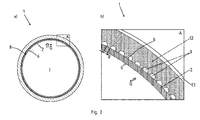
- FIG. 2a shows a cross-sectional view of the inventive evaporator tube 1 and FIG. 2b a corresponding magnification according to the section A from FIG. 2a
- FIG. 2 is good to see that from an interior I a not shown exhaust gas flow emits a heat flow Q ⁇ to the inner circumferential surface 6 of the inner tube 2. From this there is a heat conduction to the outer circumferential surface 8 of the inner tube 2, where then the heat flow Q ⁇ in the second channel, shown here in the form of an evaporation channel 9, passes.
- the evaporation channel 9 is, here represented by in cross section semicircular evaporation channels 9, formed.
- the evaporation channels 9 themselves are in direct contact with the outer circumferential surface 8 of the inner tube. 2
- a distance a is formed in each case between the individual evaporation channels 9, the sinter layer 12 being in direct contact with the outer jacket surface 8 of the inner tube 2 in the region of this distance.
- an outer mold 13 which is only schematically indicated here, can then be arranged on the sintering layer 12 from the outside.
- the outer mold 13 initially serves as a mold during the sintering process, wherein in particular within the scope of the invention, also between the outer mold 13 and inner tube 2, the entire second channel can be formed.
- a corresponding supply of the second medium and a discharge of the evaporated second medium then takes place via the in FIG. 1 shown connections in the closures 11, 12th
Landscapes
- Engineering & Computer Science (AREA)
- Manufacturing & Machinery (AREA)
- Mechanical Engineering (AREA)
- Chemical & Material Sciences (AREA)
- Composite Materials (AREA)
- Materials Engineering (AREA)
- Powder Metallurgy (AREA)
Abstract
- Bereitstellen des Innenrohres (2),
- Aufbringen eines Platzhaltermaterials auf eine Außenmantelfläche (8) des Innenrohres (2),
- Positionieren einer Außenform über das Innenrohr (2), wobei zwischen Außenmantelfläche (8) des Innenrohres (2) und Innenmantelfläche der Außenform (13) ein Ringspalt entsteht,
- Auffüllen des Ringspaltes mit einem Sinterwerkstoff,
- Sintern der Anordnung und gleichzeitiges Austreiben des Platzhaltermaterials.
Description
- Die vorliegende Erfindung betrifft ein Verfahren zum Herstellen eines Verdampferrohres gemäß den Merkmalen im Oberbegriff von Patentanspruch 1.
- Kraftfahrzeuge werden heutzutage nach wie vor als Hauptenergiequelle mit fossilen Brennstoffen über eine Verbrennungskraftmaschine angetrieben. Da diese jedoch endlich sind, ist es das Bestreben, die Energieentnahmeeffizienz für einen jeden Brennstoff zu maximieren. Dabei ist der reine Verbrennungsvorgang auf den maximalen Wirkungsgrad von 40 % des ideellen Carnotprozesses naturgesetzlich beschränkt. Dies bedeutet, dass von den 100 % Energie, die im Kraftstoff enthalten sind, maximal 40 % in Bewegungsenergie umsetzbar sind und die restliche Energie über Wärme abgeführt wird. Hierzu ist es aus dem Stand der Technik jedoch bekannt, die beim Verbrennungsvorgang entstehende Wärme mittels Kraftwärmekopplung zu nutzen. So werden Arbeitsmedien über Wärmetauscher erhitzt, wobei die in der Wärme enthaltene Energie ebenfalls dazu genutzt wird, weitere Energie zum Betrieb des Kraftfahrzeugs oder Peripheriekomponenten bereit zu stellen.
- Aus der
WO 2009/157611 A1 ist hierzu eine Herstellungsmethode für einen Wärmetauscher bekannt, bei dem in eine Oberfläche Rillen eingebracht werden, diese mit einem temporären Platzhalter gefüllt werden, und im Anschluss daran der Wärmetauscher mit einem Sintermaterial versehen wird, das nach der Zuführung von Wärme eine poröse Struktur beibehält. Ein solches Herstellungsverfahren ist jedoch kostenintensiv, da eine Bearbeitung des Grundkörpers notwendig ist und eine erhöhte Wandstärke benötigt wird. Zudem ist eine solche Fertigung nicht auf ein radiales Design übertragbar. - Aufgabe der vorliegenden Erfindung ist es, ausgehend vom Stand der Technik, ein Herstellungsverfahren für ein Verdampferrohr aufzuzeigen, dass gegenüber aus dem Stand der Technik bekannten Herstellungsverfahren deutlich einfacher und zugleich kostengünstiger durchführbar ist, wobei das dabei hergestellte Verdampferrohr verbesserte Wärmeübertragungseigenschaften aufweist.
- Die zuvor genannte Aufgabe wird erfindungsgemäß mit einem Verfahren gemäß den Merkmalen im Patentanspruch 1 gelöst.
- Vorteilhafte Ausführungsvarianten des Verfahrens sind Gegenstand der abhängigen Patentansprüche.
- Das erfindungsgemäße Verfahren zum Herstellen eines Verdampferrohres, wobei das Verdampferrohr insbesondere in einem Kraftfahrzeugwärmetauscher eingesetzt wird und das Verdampferrohr ein Innenrohr mit einem ersten Kanal zur Durchleitung eines ersten Mediums und einen das Innenrohr umhüllenden zweiten Kanal zum Verdampfen eines zweiten Mediums aufweist, ist gekennzeichnet durch folgende Verfahrensschritte:
- Bereitstellen des Innenrohres,
- Aufbringen eines Platzhaltermaterials auf eine Außenmantelfläche des Innenrohres,
- Positionieren einer Außenform über das Innenrohr, wobei zwischen Außenmantelfläche des Innenrohres und Innenmantelfläche des Mantelrohres ein Ringspalt entsteht,
- Auffüllen des Ringspaltes mit einem Sinterwerkstoff,
- Sintern der Anordnung und gleichzeitiges Austreiben des Platzhaltermaterials.
- Mit dem erfindungsgemäßen Herstellungsverfahren ist es somit möglich, eine Kanalstruktur in der durch den Sinterwerkstoff hergestellten Sinterschicht zu erzeugen, wobei das Platzhaltermaterial zur Herstellung der Kanalstruktur während des Sinterprozesses selber ausgetrieben wird. Insbesondere wird dabei ein Platzhaltermaterial verwendet, das bei den auftretenden Sintertemperaturen aufschmilzt und aus dem Kanalsystem ausfließt oder verdampft. Dort, wo das Platzhaltermaterial angeordnet war, entsteht somit ein Kanalsystem an der Außenmantelfläche des Innenrohres. Bei der Außenform handelt es sich bevorzugt um ein Mantelrohr. Die Außenform kann auch als Drahtgewebe ausgebildet sein. Das Mantelrohr kann im Querschnitt kreisrund oder auch elliptisch ausgebildet sein. In Längsrichtung kann das Mantelrohr auch konisch verlaufen.
- In der Sinterschicht selber wird dabei eine Kapillarstruktur aufgrund einer Porosität des Sintermaterials erzeugt, sodass das zweite Medium durch die entstehenden Kanäle durch den zweiten Kanal fließt und von dem ersten Kanal über das Innenrohr ein Wärmestrom von dem ersten Medium in das zweite Medium eingebracht wird. Hierdurch verdampft das zweite Medium derart, dass der entstehende Dampf über Dampfkanäle abgeführt wird. Der Dampf wird dann an einem Kondensator wiederum in den flüssigen Zustand überführt und hierbei zusätzliche Energie gewonnen, die bei dem ersten Kanal insbesondere in Form eines Abgaskanals dem Abgas entzogen wird. Aufgrund der Kapillarwirkung strömt gleichzeitig mit der Verdampfung flüssiges Medium in die Sinterstruktur nach.
- Der Arbeitskreisprozess kann beispielsweise nach dem Prinzip eines Clausius-Rankine-Prozesses erfolgen. Besonders bevorzugt werden die Verdampferrohre als heat-pipe, mithin als Wärmerohre ausgebildet und besonders bevorzugt als loopheat-pipe.
- Durch das erfindungsgemäße Verfahren entfällt gänzlich ein mechanisches Bearbeiten der hergestellten Rohranordnung. Die notwendigen Arbeitsschritte sind dabei auf ein Minimum begrenzt, wobei aufwendige spanabhebende Vor- oder Nachbearbeitungsverfahren gänzlich entfallen. Gerade unter Verwendung eines derartigen Sinterwerkstoffes, der nicht zusätzlich verdichtet wird, entsteht durch den Sintervorgang selbst eine hinreichend hohe Porosität in der Sinterschicht, so dass eine optimale Pumpwirkung und mithin ein Abführen des Dampfes ermöglicht ist.
- Hierzu wird insbesondere für das Platzhaltermaterial selbst ein Kunststoffmaterial verwendet, wobei dies insbesondere ein Polymerwerkstoff ist. Alternativ kann auch ein Amidwachs verwendet werden. Das derartige Platzhaltermaterial wird insbesondere auf die Außenmantelfläche angelegt oder aufgewickelt oder aufgespritzt. Optional wird auf die Außenmantelfläche ein Haftmittel aufgebracht, wobei das Haftmittel eine bessere stoffschlüssige Verbindung zwischen Außenmantelfläche und Platzhaltermaterial und/oder Außenmantelfläche und Sinterwerkstoff erzeugt.
- Besonders bevorzugt wird dabei das Platzhaltermaterial beispielsweise im festen Aggregatzustand bereitgestellt und ganz besonders bevorzugt in Strangform. Die derartigen Stränge des Platzhaltermaterials werden dann auf die Außenmantelfläche aufgelegt bzw. aufgepresst und mit der Außenmantelfläche zumindest temporär verklebt. Im Rahmen der Erfindung sind die Stränge verpresst oder verklebt. Insbesondere wird das Platzhaltermaterial dabei streifenförmig aufgebracht, wobei die Streifen, dargestellt durch die Stränge, bevorzugt parallel zueinander beabstandet sind. Die Streifen wiederum sind insbesondere weiterhin parallel zur Mittellängsachse des Innenrohres verlaufend oder aber die Streifen sind schraubenförmig auf der Außenmantelfläche aufgebracht. Bei letzterer Variante verlaufen die Streifen in einem Winkel zur Mittellängsachse des Innenrohres und winden sich schraubenförmig um die Außenmantelfläche.
- Im Rahmen der Erfindung ist es jedoch auch möglich, dass das Platzhaltermaterial in einem flüssigen, gelförmigen oder pastösen Aggregatzustand auf die Außenmantelfläche aufgespritzt wird. Das Platzhaltermaterial weist in diesem Aggregatzustand eine Eigenklebfunktion auf, so dass ein zusätzlicher Klebevorgang nicht durchgeführt werden muss.
- Ein zwischen Außenform und Innenrohr entstehender Ringspalt wird nunmehr mit Sinterwerkstoff aufgefüllt.
- Während des folgenden Sintervorganges, bei dem unter Umständen ein Vakuumsintervorgang verwendet werden kann, aber auch ein anderweitiger Sintervorgang nicht unter Vakuumatmosphäre durchgeführt werden kann schmilzt das Platzhaltermaterial auf und fließt aus dem Ringspalt aus. Als Temperaturen werden bevorzugt 500° bis 1200° C, insbesondere 900° bis 1100° C verwendet. Hierbei schmilzt das Platzhaltermaterial auf und läuft über die dabei entstehenden Kanäle aus der Anordnung aus. Alternativ kann das Platzhaltermaterial auch bei circa 600° zuvor bei Verfestigung des Sintermaterials ausgetrieben werden und anschließend der eigentliche Sintervorgang durchgeführt werden. Das Platzhaltermaterial selbst fängt in einem Temperaturbereich zwischen 150 °C und 450 °C, insbesondere 200 °C bis 400 °C an aufzuschmelzen bzw. zu verdampfen. Bis das Platzhaltermaterial vollständig aufgeschmolzen bzw. vollständig verdampft ist, hat die Anordnung weiterhin eine Temperatur erreicht, bei der der Sintervorgang bereits begonnen hat, wodurch sich der Sinterwerkstoff dann beginnt zu verbinden. Durch bevorzugten Einsatz eines nachfolgend erläuterten Sinterwerkstoffes in Form eines spratzigen Metallpulvers, kann jedoch auch sichergestellt werden, dass selbst bei nahezu vollständig ausgeflossenem bzw. verdampftem Platzhaltermaterial zunächst die hergestellte Kanalstruktur erhalten bleibt bei erst danach einsetzendem Sinterprozess.
- Damit der Sinterwerkstoff nicht die durch das ausfließende bzw. verdampfende Platzhaltermaterial entstehenden Hohlräume durch ein eigenes Nachrücken wieder verschließt, wird insbesondere ein spratziges Metallpulver verwendet. Unter spratzigem Metallpulver ist eine eckige und/oder kantige Pulverform zu verstehen, so dass sich die einzelnen Pulverteilchen untereinander verhaken und/oder verkanten und bis zum Abschluss des Sintervorganges formstabil zueinander ausgerichtet bleiben. Die Pulverpartikel sind somit eckig bzw. kantig oder vieleckig derart ausgebildet, dass sie sich untereinander verhaken und/oder verkanten. Durch die dabei entstehenden Kanalstrukturen fließt dann im späteren Einsatz das zweite Medium, insbesondere ein Arbeitsmedium, im gasförmigen Aggregatzustand. Durch die aufgrund des spratzigen Metallpulvers entstehenden rauen Oberflächen innerhalb der Kanalstruktur selber wird dabei eine turbulente Strömung erzeugt, die einen verbesserten Wärmeübergang in das zweite Medium erzeugt, wodurch eine stärkere Überhitzung des Dampfes stattfindet. Die Pumpfunktion ist dabei derart bevorzugt anzusehen, dass eine aktive Pumpe entfallen kann und die Pumpfunktion ausschließlich durch die Kapillarfunktion erfolgt.
- Weiterhin besonders bevorzugt wird für das Sintermaterial ein Edelstahlwerkstoff verwendet. Insbesondere sind weiterhin das Innenrohr, das Sintermaterial und das optionale Mantelrohr ebenfalls aus einem Edelstahlwerkstoff ausgebildet, da dieser eine besonders gute Resistenz gegen die korrosiven Eigenschaften des Abgases aufweist bei gleichzeitig guter Wärmeleitfähigkeit. Sind alle Bauteilkomponenten aus demselben Werkstoff ausgebildet, so weist der Werkstoff entsprechend gleiche Wärmeausdehnungskoeffizienten auf, so dass die Anordnung insbesondere in Bezug auf die Dauerhaltbarkeit bei thermischen Ausdehnungen keinen Schaden annimmt.
- Insbesondere sind das Innenrohr, der Sinterwerkstoff und optional das Mantelrohr dabei aus einem Edelstahlwerkstoff der 1.4XXX-Gruppe, ganz besonders bevorzugt aus einer Edelstahllegierung 1.4404 hergestellt.
- Die in dem Ringspalt aufgeführte Sinterstruktur wird erfindungsgemäß nicht verdichtet. Optional ergänzend oder aber alternativ weist die aus dem Sinterwerkstoff hergestellte Sinterschicht eine Porosität von mehr als 50 % auf, insbesondere zwischen 50 % und 80 %, bevorzugt zwischen 50 % und 60 %, wobei zwischen der Sinterschicht und der Außenmantelfläche des Innenrohres eine Kontaktfläche von 40 % bis 60 %, insbesondere 50 % hergestellt ist. Letzteres bedeutet im Rahmen der Erfindung, dass 40 % bis 60 %, insbesondere 50 % der Außenmantelfläche des Innenrohres in Kontakt mit der Sinterschicht steht. Hierdurch wird ein Optimum erreicht zwischen hergestellter Kanalstruktur und direktem Wärmeübergang von erstem in zweites Medium, was zum Verdampfen des zweiten Mediums genutzt wird.
- Damit die Sinterschicht und die Kapillarstruktur ebenfalls eine ausreichende Wärme aus einem Wärmeeintrag erlangen, wird dann über die Kontaktfläche zwischen Außenmantelfläche des Innenrohres und Sinterschicht Wärme in die Sinterschicht überführt aufgrund von Wärmeleitung. In der Sinterschicht erfolgt dann aufgrund der Kapillarstruktur eine Pumpfunktion und ein Abführen des verdampften zweiten Mediums.
- Das erfindungsgemäße Verfahren sieht weiterhin vor, dass der Sinterwerkstoff durch den Sintervorgang stoffschlüssig mit der Außenmantelfläche des Innenrohres gekoppelt wird.
- Weiterhin ist es möglich, Anbauteile, beispielsweise Verschlussstopfen oder aber Anschlüsse insbesondere für den zweiten Kanal mit dem Innenrohr und/oder mit dem Mantelrohr stoffschlüssig zu koppeln, insbesondere durch einen Lötvorgang, wobei der Lötvorgang gleichzeitig und parallel mit dem Sintervorgang durchgeführt wird. Beides kann in einer gleichen Erwärmungseinrichtung durchgeführt werden, beispielsweise einem Ofen. Insbesondere wird dies bei Temperaturen von im Wesentlichen 800° bis 1200° und ganz besonders bevorzugt 900° bis 1100° und optional unter Schutzgas durchgeführt.
- Weiterhin besonders bevorzugt ist die Außenform an ihrer Innenmantelfläche mit einem hochtemperaturbeständigen Trennmittel versehen. Hierdurch wird es ermöglicht, nach dem Sintervorgang und einem Aushärten des Sinterwerkstoffes das Mantelrohr abzuziehen.
- Weitere Vorteile, Merkmale, Eigenschaften und Aspekte der vorliegenden Erfindung sind Gegenstand der nachfolgenden Beschreibung. Bevorzugte Ausführungsvarianten werden in den schematischen Figuren dargestellt. Diese dienen dem einfachen Verständnis der Erfindung. Es zeigen:
- Figur 1
- ein erfindungsgemäßes Verdampferrohr in Längsschnittsansicht;
- Figur 2a
- ein erfindungsgemäß hergestelltes Verdampferrohr in Querschnitts-
- und b
- ansicht und vergrößerter Ansicht des Querschnittes.
- In den Figuren werden für gleiche oder ähnliche Bauteile dieselben Bezugszeichen verwendet, auch wenn eine wiederholte Beschreibung aus Vereinfachungsgründen entfällt.
-
Figur 1 zeigt ein erfindungsgemäßes Verdampferrohr 1, aufweisend ein Innenrohr 2 und ein das Innenrohr 2 auf seine Längsrichtung 4 bezogen zumindest abschnittsweise umhüllendes Gehäuserohr 3. Zwischen dem Gehäuserohr 3 und dem Innenrohr 2 ist eine Kapillarstruktur angeordnet, die inFigur 2a und b im Detail näher erläutert wird. In dem Innenrohr 2 selbst ist ein erster Kanal 5 ausgebildet, durch den ein erstes Medium leitbar ist, so dass das erste Medium an eine Innenmantelfläche 6 des Innenrohrs 2 einen Wärmestrom abgibt, der dann durch die Mantelfläche 7 des Innenrohrs 2 hindurchströmt und in die Kapillarstruktur K mittels Wärmeleitung überführt wird. Zwischen der Außenmantelfläche 8 und dem Gehäuserohr 3 selbst ist ein zweiter Kanal 9 in Form eines Verdampfungsrohres ausgebildet, durch den ein zweites Medium strömt, wobei der Verdampfungskanal eine Kapillarstruktur K aufweist. Hierzu sind Verschlüsse 10, 11 jeweils endseitig angesetzt, die den zweiten Kanal 9 abschließen. Die Verschlüsse 10, 11 selber können weitere Anschlüsse aufweisen oder aber als Anschluss selbst ausgebildet sein, um das zweite Medium in den zweiten Kanal 9 einzuleiten. -
Figur 2a zeigt eine Querschnittsansicht des erfindungsgemäßen Verdampferrohres 1 undFigur 2b eine entsprechende Vergrößerung gemäß dem Ausschnitt A ausFigur 2a . InFigur 2 ist gut zu erkennen, dass von einem Innenraum I ein nicht näher dargestellter Abgasstrom einen Wärmestrom Q̇ an die Innenmantelfläche 6 des Innenrohrs 2 abgibt. Von dieser erfolgt eine Wärmeleitung an die Außenmantelfläche 8 des Innenrohrs 2, wo dann der Wärmestrom Q̇ in den zweiten Kanal, hier dargestellt in Form eines Verdampfungskanals 9, übergeht. Der Verdampfungskanal 9 ist dabei, hier dargestellt durch im Querschnitt halbrunde Verdampfungskanäle 9, ausgebildet. Die Verdampfungskanäle 9 selbst stehen in direktem Kontakt mit der Außenmantelfläche 8 des Innenrohres 2. - Zwischen den einzelnen Verdampfungskanälen 9 ist jeweils ein Abstand a ausgebildet, wobei im Bereich dieses Abstandes die Sinterschicht 12 in direktem Kontakt mit der Außenmantelfläche 8 des Innenrohres 2 steht. Hierdurch erfolgt ein Wärmeeintrag in die Sinterschicht 12 selber, so dass eine nicht näher dargestellte Kapillarstruktur innerhalb der porösen Sinterschicht 12 ebenfalls erwärmt wird. Optional kann dann ein hier schematisch nur angedeutete Außenform 13 von außen an der Sinterschicht 12 angeordnet sein. Die Außenform 13 dient zunächst als Form während des Sintervorganges, wobei insbesondere im Rahmen der Erfindung auch zwischen Außenform 13 und Innenrohr 2 der gesamte zweite Kanal ausgebildet sein kann. Ein entsprechendes Zuführen des zweiten Mediums und ein Abführen des verdampften zweiten Mediums erfolgt dann über die in
Figur 1 dargestellten Anschlüsse in den Verschlüssen 11, 12. - Bezugszeichen:
- 1 -
- Verdampferrohr
- 2 -
- Innenrohr
- 3 -
- Gehäuserohr
- 4 -
- Längsrichtung zu 2
- 5 -
- erster Kanal
- 6 -
- Innenmantelfläche zu 2
- 7 -
- Mantelfläche zu 2
- 8 -
- Außenmantelfläche zu 2
- 9 -
- Verdampfungskanal
- 10 -
- Verschluss
- 11 -
- Verschluss
- 12 -
- Sinterschicht
- 13 -
- Außenform
- I -
- Innenraum
- K -
- Kappilarstruktur
- a -
- Abstand
- Q̇ -
- Wärmestrom
Claims (12)
- Verfahren zum Herstellen eines Verdampferrohres (1), insbesondere für einen Kraftfahrzeugwärmetauscher, wobei das Verdampferrohr (1) ein Innenrohr (2) mit einem ersten Kanal (5) zur Durchleitung eines ersten Mediums und einen das Innenrohr (2) umhüllenden zweiten Kanal zum Verdampfen eines zweiten Mediums aufweist, gekennzeichnet durch folgende Verfahrensschritte:- Bereitstellen des Innenrohres (2),- Aufbringen eines Platzhaltermaterials auf eine Außenmantelfläche (8) des Innenrohres (2),- Positionieren einer Außenform (13) über das Innenrohr (2), wobei zwischen Außenmantelfläche (8) des Innenrohres (2) und Innenmantelfläche (6) der Außenform (13) ein Ringspalt entsteht,- Auffüllen des Ringspaltes mit einem Sinterwerkstoff,- Sintern der Anordnung und gleichzeitiges Austreiben des Platzhaltermaterials.
- Verfahren zum Herstellen eines Verdampferrohres nach Patentanspruch 1, dadurch gekennzeichnet, dass als Platzhaltermaterial ein Kunststoffmaterial verwendet wird, insbesondere ein Polymerwerkstoff.
- Verfahren zum Herstellen eines Verdampferrohres nach Patentanspruch 1 oder 2, dadurch gekennzeichnet, dass das Platzhaltermaterial auf die Außenmantelfläche (8) angelegt oder aufgewickelt oder aufgespritzt wird.
- Verfahren zum Herstellen eines Verdampferrohres nach einem der vorhergehenden Ansprüche, dadurch gekennzeichnet, dass auf die Außenmantelfläche (8) ein Haftmittel aufgebracht wird.
- Verfahren zum Herstellen eines Verdampferrohres nach einem der vorhergehenden Ansprüche, dadurch gekennzeichnet, dass als Sintermaterial ein spratziges Metallpulver verwendet wird, insbesondere aus einem Edelstahl.
- Verfahren zum Herstellen eines Verdampferrohres nach einem der vorhergehenden Ansprüche, dadurch gekennzeichnet, dass die Außenform (13) an ihrer Innenmantelfläche (6) mit einem hochtemperaturbeständigen Trennmittel versehen wird.
- Verfahren zum Herstellen eines Verdampferrohres nach einem der vorhergehenden Ansprüche, dadurch gekennzeichnet, dass das Platzhaltermaterial streifenförmig aufgebracht wird, wobei die Streifen bevorzugt parallel zueinander beabstandet sind.
- Verfahren zum Herstellen eines Verdampferrohres nach einem der vorhergehenden Ansprüche, dadurch gekennzeichnet, dass die Streifen parallel zur Mittellängsachse des Innenrohres (2) aufgebracht werden oder das die Streifen schraubenförmig um die Außenmantelfläche (8) verlaufen.
- Verfahren zum Herstellen eines Verdampferrohres nach einem der vorhergehenden Ansprüche, dadurch gekennzeichnet, dass das Innenrohr (2), der Sinterwerkstoff und optional die Außenform (13) aus dem gleichen Werkstoff ausgebildet sind, insbesondere aus einem Edelstahl.
- Verfahren zum Herstellen eines Verdampferrohres nach einem der vorhergehenden Ansprüche, dadurch gekennzeichnet, dass der Sinterwerkstoff nicht verdichtet wird und/oder dass die Sinterschicht (12) eine Porosität von mehr als 50% aufweist, insbesondere zwischen 50 und 80%, bevorzugt zwischen 50 und 60% und dass zwischen Sinterschicht (12) und Außenmantelfläche (8) des Innenrohres (2) eine Kontaktfläche von 40 bis 60%, insbesondere 50% hergestellt ist.
- Verfahren zum Herstellen eines Verdampferrohres nach einem der vorhergehenden Ansprüche, dadurch gekennzeichnet, dass der Sinterwerkstoff durch den Sintervorgang stoffschlüssig mit der Außenmantelfläche (8) des Innenrohrs (2) gekoppelt wird und/oder das weitere Anbauteile mit dem Verdampferrohr (1) durch einen Lötprozess gekoppelt werden, wobei der Lötprozess und der Sintervorgang gleichzeitig und in einer gleichen Erwärmungseinrichtung durchgeführt werden.
- Verfahren zum Herstellen eines Verdampferrohres nach einem der vorhergehenden Ansprüche, dadurch gekennzeichnet, dass das Platzhaltermaterial durch die Temperatureinwirkung des Sintern aufschmilzt und aus der Anordnung ausfließt oder verdampft.
Applications Claiming Priority (1)
| Application Number | Priority Date | Filing Date | Title |
|---|---|---|---|
| DE102013103836.0A DE102013103836B4 (de) | 2013-04-16 | 2013-04-16 | Verfahren zum Herstellen eines Verdampferrohres |
Publications (2)
| Publication Number | Publication Date |
|---|---|
| EP2792437A1 true EP2792437A1 (de) | 2014-10-22 |
| EP2792437B1 EP2792437B1 (de) | 2015-11-04 |
Family
ID=50230893
Family Applications (1)
| Application Number | Title | Priority Date | Filing Date |
|---|---|---|---|
| EP14157192.7A Not-in-force EP2792437B1 (de) | 2013-04-16 | 2014-02-28 | Verfahren zum Herstellen eines Verdampferrohres |
Country Status (2)
| Country | Link |
|---|---|
| EP (1) | EP2792437B1 (de) |
| DE (1) | DE102013103836B4 (de) |
Cited By (1)
| Publication number | Priority date | Publication date | Assignee | Title |
|---|---|---|---|---|
| EP3095704A1 (de) * | 2015-05-21 | 2016-11-23 | FINMECCANICA-Società per azioni | Wärmerückgewinnungssystem, insbesondere zur verwendung in einem flugzeug, mit einem zweiphasigen flüssigkeitskreislauf |
Citations (5)
| Publication number | Priority date | Publication date | Assignee | Title |
|---|---|---|---|---|
| US3345160A (en) * | 1965-07-09 | 1967-10-03 | Carborundum Co | Method for making ducted refractory articles |
| US3751271A (en) * | 1970-05-12 | 1973-08-07 | Toyota Kk | Sintered filter having straight holes therethrough |
| WO2002044639A1 (en) * | 2000-11-30 | 2002-06-06 | Khpt Co., Ltd | Sintered wick structure heat pipe with parallel pipe holes and manufature method thereof |
| WO2009157611A1 (en) * | 2008-06-23 | 2009-12-30 | Zalman Tech Co., Ltd. | Method for manufacturing evaporator for loop heat pipe system |
| DE102011103110A1 (de) * | 2011-05-25 | 2012-11-29 | Benteler Automobiltechnik Gmbh | Abgassystem mit Kreislaufwärmerohr |
-
2013
- 2013-04-16 DE DE102013103836.0A patent/DE102013103836B4/de not_active Expired - Fee Related
-
2014
- 2014-02-28 EP EP14157192.7A patent/EP2792437B1/de not_active Not-in-force
Patent Citations (5)
| Publication number | Priority date | Publication date | Assignee | Title |
|---|---|---|---|---|
| US3345160A (en) * | 1965-07-09 | 1967-10-03 | Carborundum Co | Method for making ducted refractory articles |
| US3751271A (en) * | 1970-05-12 | 1973-08-07 | Toyota Kk | Sintered filter having straight holes therethrough |
| WO2002044639A1 (en) * | 2000-11-30 | 2002-06-06 | Khpt Co., Ltd | Sintered wick structure heat pipe with parallel pipe holes and manufature method thereof |
| WO2009157611A1 (en) * | 2008-06-23 | 2009-12-30 | Zalman Tech Co., Ltd. | Method for manufacturing evaporator for loop heat pipe system |
| DE102011103110A1 (de) * | 2011-05-25 | 2012-11-29 | Benteler Automobiltechnik Gmbh | Abgassystem mit Kreislaufwärmerohr |
Cited By (2)
| Publication number | Priority date | Publication date | Assignee | Title |
|---|---|---|---|---|
| EP3095704A1 (de) * | 2015-05-21 | 2016-11-23 | FINMECCANICA-Società per azioni | Wärmerückgewinnungssystem, insbesondere zur verwendung in einem flugzeug, mit einem zweiphasigen flüssigkeitskreislauf |
| US10029800B2 (en) | 2015-05-21 | 2018-07-24 | Leonardo S.P.A. | Heat recovery system, in particular for use on aircraft, using a two-phase fluid circuit |
Also Published As
| Publication number | Publication date |
|---|---|
| EP2792437B1 (de) | 2015-11-04 |
| DE102013103836B4 (de) | 2018-05-03 |
| DE102013103836A1 (de) | 2014-10-16 |
Similar Documents
| Publication | Publication Date | Title |
|---|---|---|
| EP2799805B1 (de) | Verdampferrohr zur Anordnung in einem Abgasstrang sowie Verfahren zur Herstellung des Verdampferrohres mit poröser Sinterstruktur und Dampfkanälen | |
| EP2510302B1 (de) | Wärmeübertragungsrohr | |
| EP2492119A2 (de) | Latentwärmespeicher | |
| DE112017000580T5 (de) | Additiv gefertigte rotoren für kompressoren und expander querverweis auf verwandte anmeldungen | |
| DE602006000885T2 (de) | Rotor für eine elektrische Maschine | |
| DE102008060116A1 (de) | Verfahren zur Herstellung einer Lageranordnung und Lageranordnung | |
| DE102013226664A1 (de) | Turbinenläufer und Verfahren zur Herstellung des Turbinenläufers | |
| DE102013226732A1 (de) | Adsorberstruktur | |
| DE102010011486A1 (de) | Rotor für eine Ladeeinrichtung | |
| EP2314971B1 (de) | Wärmespeicher mit Energieeinspeisung zur langzeitstabilen und gleichmäßigen Leistungsabgabe und Verfahren hierzu | |
| DE102012217560A1 (de) | Turbinenläufer mit Hülsenzwischenstück, Abgasturbolader und ein Verfahren zur Herstellung des Turbinenläufers | |
| EP2792437B1 (de) | Verfahren zum Herstellen eines Verdampferrohres | |
| WO2010100214A2 (de) | Läufer für einen elektromotor und verfahren zur herstellung eines solchen läufers | |
| DE102009040930A1 (de) | Heizbarer Flüssigkeitsbehälter aus Kunststoffmaterial und Verfahren zu seiner Herstellung | |
| EP3054259A1 (de) | Verfahren zur herstellung eines wärmetauschers | |
| DE102019124788A1 (de) | Verfahren zum Betreiben einer Antriebseinrichtung für ein Kraftfahrzeug sowie entsprechende Antriebseinrichtung | |
| WO2017016646A1 (de) | Wärmeübertragungsrohr, wärmespeicher und verfahren zum herstellen eines wärmeübertragungsrohrs | |
| WO2017016647A1 (de) | Wärmeübertragungsrohr, wärmespeicher und verfahren zum herstellen eines wärmeübertragungsrohrs | |
| WO2016055233A1 (de) | Heizkörper für eine elektrisch beheizbare glühstiftkerze mit axial gepresstem heizeinsatz, und zugehöriges herstellungsverfahren | |
| EP2527761A2 (de) | Vorrichtung zur Wärmeübertragung | |
| AT523430B1 (de) | Verfahren zur Herstellung eines Wärmerohres | |
| DE102012205496A1 (de) | Thermisch isoliertes Leitungselement und Verfahren zu dessen Herstellung | |
| EP2950031B1 (de) | Abgaswärmetauscher aus duplexstahl | |
| DE102011121510A1 (de) | Hitzeschild | |
| DE102012211481A1 (de) | Verfahren und Vorrichtung zum Herstellen eines Bauteils |
Legal Events
| Date | Code | Title | Description |
|---|---|---|---|
| PUAI | Public reference made under article 153(3) epc to a published international application that has entered the european phase |
Free format text: ORIGINAL CODE: 0009012 |
|
| 17P | Request for examination filed |
Effective date: 20140722 |
|
| AK | Designated contracting states |
Kind code of ref document: A1 Designated state(s): AL AT BE BG CH CY CZ DE DK EE ES FI FR GB GR HR HU IE IS IT LI LT LU LV MC MK MT NL NO PL PT RO RS SE SI SK SM TR |
|
| AX | Request for extension of the european patent |
Extension state: BA ME |
|
| GRAP | Despatch of communication of intention to grant a patent |
Free format text: ORIGINAL CODE: EPIDOSNIGR1 |
|
| INTG | Intention to grant announced |
Effective date: 20150715 |
|
| GRAS | Grant fee paid |
Free format text: ORIGINAL CODE: EPIDOSNIGR3 |
|
| GRAA | (expected) grant |
Free format text: ORIGINAL CODE: 0009210 |
|
| AK | Designated contracting states |
Kind code of ref document: B1 Designated state(s): AL AT BE BG CH CY CZ DE DK EE ES FI FR GB GR HR HU IE IS IT LI LT LU LV MC MK MT NL NO PL PT RO RS SE SI SK SM TR |
|
| REG | Reference to a national code |
Ref country code: GB Ref legal event code: FG4D Free format text: NOT ENGLISH |
|
| REG | Reference to a national code |
Ref country code: CH Ref legal event code: EP |
|
| REG | Reference to a national code |
Ref country code: AT Ref legal event code: REF Ref document number: 758849 Country of ref document: AT Kind code of ref document: T Effective date: 20151115 |
|
| REG | Reference to a national code |
Ref country code: IE Ref legal event code: FG4D Free format text: LANGUAGE OF EP DOCUMENT: GERMAN |
|
| REG | Reference to a national code |
Ref country code: DE Ref legal event code: R096 Ref document number: 502014000175 Country of ref document: DE |
|
| REG | Reference to a national code |
Ref country code: FR Ref legal event code: PLFP Year of fee payment: 3 |
|
| REG | Reference to a national code |
Ref country code: NL Ref legal event code: MP Effective date: 20151104 |
|
| REG | Reference to a national code |
Ref country code: LT Ref legal event code: MG4D |
|
| PG25 | Lapsed in a contracting state [announced via postgrant information from national office to epo] |
Ref country code: NL Free format text: LAPSE BECAUSE OF FAILURE TO SUBMIT A TRANSLATION OF THE DESCRIPTION OR TO PAY THE FEE WITHIN THE PRESCRIBED TIME-LIMIT Effective date: 20151104 Ref country code: NO Free format text: LAPSE BECAUSE OF FAILURE TO SUBMIT A TRANSLATION OF THE DESCRIPTION OR TO PAY THE FEE WITHIN THE PRESCRIBED TIME-LIMIT Effective date: 20160204 Ref country code: IS Free format text: LAPSE BECAUSE OF FAILURE TO SUBMIT A TRANSLATION OF THE DESCRIPTION OR TO PAY THE FEE WITHIN THE PRESCRIBED TIME-LIMIT Effective date: 20160304 Ref country code: ES Free format text: LAPSE BECAUSE OF FAILURE TO SUBMIT A TRANSLATION OF THE DESCRIPTION OR TO PAY THE FEE WITHIN THE PRESCRIBED TIME-LIMIT Effective date: 20151104 Ref country code: LT Free format text: LAPSE BECAUSE OF FAILURE TO SUBMIT A TRANSLATION OF THE DESCRIPTION OR TO PAY THE FEE WITHIN THE PRESCRIBED TIME-LIMIT Effective date: 20151104 Ref country code: IT Free format text: LAPSE BECAUSE OF FAILURE TO SUBMIT A TRANSLATION OF THE DESCRIPTION OR TO PAY THE FEE WITHIN THE PRESCRIBED TIME-LIMIT Effective date: 20151104 Ref country code: HR Free format text: LAPSE BECAUSE OF FAILURE TO SUBMIT A TRANSLATION OF THE DESCRIPTION OR TO PAY THE FEE WITHIN THE PRESCRIBED TIME-LIMIT Effective date: 20151104 |
|
| PG25 | Lapsed in a contracting state [announced via postgrant information from national office to epo] |
Ref country code: SE Free format text: LAPSE BECAUSE OF FAILURE TO SUBMIT A TRANSLATION OF THE DESCRIPTION OR TO PAY THE FEE WITHIN THE PRESCRIBED TIME-LIMIT Effective date: 20151104 Ref country code: FI Free format text: LAPSE BECAUSE OF FAILURE TO SUBMIT A TRANSLATION OF THE DESCRIPTION OR TO PAY THE FEE WITHIN THE PRESCRIBED TIME-LIMIT Effective date: 20151104 Ref country code: PL Free format text: LAPSE BECAUSE OF FAILURE TO SUBMIT A TRANSLATION OF THE DESCRIPTION OR TO PAY THE FEE WITHIN THE PRESCRIBED TIME-LIMIT Effective date: 20151104 Ref country code: GR Free format text: LAPSE BECAUSE OF FAILURE TO SUBMIT A TRANSLATION OF THE DESCRIPTION OR TO PAY THE FEE WITHIN THE PRESCRIBED TIME-LIMIT Effective date: 20160205 Ref country code: PT Free format text: LAPSE BECAUSE OF FAILURE TO SUBMIT A TRANSLATION OF THE DESCRIPTION OR TO PAY THE FEE WITHIN THE PRESCRIBED TIME-LIMIT Effective date: 20160304 Ref country code: RS Free format text: LAPSE BECAUSE OF FAILURE TO SUBMIT A TRANSLATION OF THE DESCRIPTION OR TO PAY THE FEE WITHIN THE PRESCRIBED TIME-LIMIT Effective date: 20151104 Ref country code: LV Free format text: LAPSE BECAUSE OF FAILURE TO SUBMIT A TRANSLATION OF THE DESCRIPTION OR TO PAY THE FEE WITHIN THE PRESCRIBED TIME-LIMIT Effective date: 20151104 Ref country code: BE Free format text: LAPSE BECAUSE OF NON-PAYMENT OF DUE FEES Effective date: 20160229 |
|
| REG | Reference to a national code |
Ref country code: DE Ref legal event code: R097 Ref document number: 502014000175 Country of ref document: DE |
|
| PG25 | Lapsed in a contracting state [announced via postgrant information from national office to epo] |
Ref country code: SM Free format text: LAPSE BECAUSE OF FAILURE TO SUBMIT A TRANSLATION OF THE DESCRIPTION OR TO PAY THE FEE WITHIN THE PRESCRIBED TIME-LIMIT Effective date: 20151104 Ref country code: SK Free format text: LAPSE BECAUSE OF FAILURE TO SUBMIT A TRANSLATION OF THE DESCRIPTION OR TO PAY THE FEE WITHIN THE PRESCRIBED TIME-LIMIT Effective date: 20151104 Ref country code: DK Free format text: LAPSE BECAUSE OF FAILURE TO SUBMIT A TRANSLATION OF THE DESCRIPTION OR TO PAY THE FEE WITHIN THE PRESCRIBED TIME-LIMIT Effective date: 20151104 Ref country code: EE Free format text: LAPSE BECAUSE OF FAILURE TO SUBMIT A TRANSLATION OF THE DESCRIPTION OR TO PAY THE FEE WITHIN THE PRESCRIBED TIME-LIMIT Effective date: 20151104 Ref country code: RO Free format text: LAPSE BECAUSE OF FAILURE TO SUBMIT A TRANSLATION OF THE DESCRIPTION OR TO PAY THE FEE WITHIN THE PRESCRIBED TIME-LIMIT Effective date: 20151104 |
|
| PLBE | No opposition filed within time limit |
Free format text: ORIGINAL CODE: 0009261 |
|
| STAA | Information on the status of an ep patent application or granted ep patent |
Free format text: STATUS: NO OPPOSITION FILED WITHIN TIME LIMIT |
|
| PG25 | Lapsed in a contracting state [announced via postgrant information from national office to epo] |
Ref country code: MC Free format text: LAPSE BECAUSE OF FAILURE TO SUBMIT A TRANSLATION OF THE DESCRIPTION OR TO PAY THE FEE WITHIN THE PRESCRIBED TIME-LIMIT Effective date: 20151104 Ref country code: LU Free format text: LAPSE BECAUSE OF FAILURE TO SUBMIT A TRANSLATION OF THE DESCRIPTION OR TO PAY THE FEE WITHIN THE PRESCRIBED TIME-LIMIT Effective date: 20160228 |
|
| 26N | No opposition filed |
Effective date: 20160805 |
|
| PG25 | Lapsed in a contracting state [announced via postgrant information from national office to epo] |
Ref country code: SI Free format text: LAPSE BECAUSE OF FAILURE TO SUBMIT A TRANSLATION OF THE DESCRIPTION OR TO PAY THE FEE WITHIN THE PRESCRIBED TIME-LIMIT Effective date: 20151104 |
|
| REG | Reference to a national code |
Ref country code: IE Ref legal event code: MM4A |
|
| PG25 | Lapsed in a contracting state [announced via postgrant information from national office to epo] |
Ref country code: IE Free format text: LAPSE BECAUSE OF NON-PAYMENT OF DUE FEES Effective date: 20160228 |
|
| REG | Reference to a national code |
Ref country code: FR Ref legal event code: PLFP Year of fee payment: 4 |
|
| PG25 | Lapsed in a contracting state [announced via postgrant information from national office to epo] |
Ref country code: MT Free format text: LAPSE BECAUSE OF FAILURE TO SUBMIT A TRANSLATION OF THE DESCRIPTION OR TO PAY THE FEE WITHIN THE PRESCRIBED TIME-LIMIT Effective date: 20151104 |
|
| REG | Reference to a national code |
Ref country code: CH Ref legal event code: PL |
|
| PG25 | Lapsed in a contracting state [announced via postgrant information from national office to epo] |
Ref country code: LI Free format text: LAPSE BECAUSE OF NON-PAYMENT OF DUE FEES Effective date: 20170228 Ref country code: CH Free format text: LAPSE BECAUSE OF NON-PAYMENT OF DUE FEES Effective date: 20170228 |
|
| REG | Reference to a national code |
Ref country code: FR Ref legal event code: PLFP Year of fee payment: 5 |
|
| PGFP | Annual fee paid to national office [announced via postgrant information from national office to epo] |
Ref country code: GB Payment date: 20180216 Year of fee payment: 5 Ref country code: CZ Payment date: 20180227 Year of fee payment: 5 |
|
| PG25 | Lapsed in a contracting state [announced via postgrant information from national office to epo] |
Ref country code: HU Free format text: LAPSE BECAUSE OF FAILURE TO SUBMIT A TRANSLATION OF THE DESCRIPTION OR TO PAY THE FEE WITHIN THE PRESCRIBED TIME-LIMIT; INVALID AB INITIO Effective date: 20140228 |
|
| PGFP | Annual fee paid to national office [announced via postgrant information from national office to epo] |
Ref country code: FR Payment date: 20180223 Year of fee payment: 5 |
|
| PG25 | Lapsed in a contracting state [announced via postgrant information from national office to epo] |
Ref country code: MK Free format text: LAPSE BECAUSE OF FAILURE TO SUBMIT A TRANSLATION OF THE DESCRIPTION OR TO PAY THE FEE WITHIN THE PRESCRIBED TIME-LIMIT Effective date: 20151104 Ref country code: CY Free format text: LAPSE BECAUSE OF FAILURE TO SUBMIT A TRANSLATION OF THE DESCRIPTION OR TO PAY THE FEE WITHIN THE PRESCRIBED TIME-LIMIT Effective date: 20151104 |
|
| PG25 | Lapsed in a contracting state [announced via postgrant information from national office to epo] |
Ref country code: BG Free format text: LAPSE BECAUSE OF FAILURE TO SUBMIT A TRANSLATION OF THE DESCRIPTION OR TO PAY THE FEE WITHIN THE PRESCRIBED TIME-LIMIT Effective date: 20151104 |
|
| PG25 | Lapsed in a contracting state [announced via postgrant information from national office to epo] |
Ref country code: AL Free format text: LAPSE BECAUSE OF FAILURE TO SUBMIT A TRANSLATION OF THE DESCRIPTION OR TO PAY THE FEE WITHIN THE PRESCRIBED TIME-LIMIT Effective date: 20151104 Ref country code: TR Free format text: LAPSE BECAUSE OF FAILURE TO SUBMIT A TRANSLATION OF THE DESCRIPTION OR TO PAY THE FEE WITHIN THE PRESCRIBED TIME-LIMIT Effective date: 20151104 |
|
| PGFP | Annual fee paid to national office [announced via postgrant information from national office to epo] |
Ref country code: DE Payment date: 20190227 Year of fee payment: 6 |
|
| GBPC | Gb: european patent ceased through non-payment of renewal fee |
Effective date: 20190228 |
|
| PG25 | Lapsed in a contracting state [announced via postgrant information from national office to epo] |
Ref country code: CZ Free format text: LAPSE BECAUSE OF NON-PAYMENT OF DUE FEES Effective date: 20190228 |
|
| PG25 | Lapsed in a contracting state [announced via postgrant information from national office to epo] |
Ref country code: GB Free format text: LAPSE BECAUSE OF NON-PAYMENT OF DUE FEES Effective date: 20190228 |
|
| PG25 | Lapsed in a contracting state [announced via postgrant information from national office to epo] |
Ref country code: FR Free format text: LAPSE BECAUSE OF NON-PAYMENT OF DUE FEES Effective date: 20190228 |
|
| REG | Reference to a national code |
Ref country code: AT Ref legal event code: MM01 Ref document number: 758849 Country of ref document: AT Kind code of ref document: T Effective date: 20190228 |
|
| PG25 | Lapsed in a contracting state [announced via postgrant information from national office to epo] |
Ref country code: AT Free format text: LAPSE BECAUSE OF NON-PAYMENT OF DUE FEES Effective date: 20190228 |
|
| REG | Reference to a national code |
Ref country code: DE Ref legal event code: R119 Ref document number: 502014000175 Country of ref document: DE |
|
| PG25 | Lapsed in a contracting state [announced via postgrant information from national office to epo] |
Ref country code: DE Free format text: LAPSE BECAUSE OF NON-PAYMENT OF DUE FEES Effective date: 20200901 |