EP3095704A1 - Wärmerückgewinnungssystem, insbesondere zur verwendung in einem flugzeug, mit einem zweiphasigen flüssigkeitskreislauf - Google Patents
Wärmerückgewinnungssystem, insbesondere zur verwendung in einem flugzeug, mit einem zweiphasigen flüssigkeitskreislauf Download PDFInfo
- Publication number
- EP3095704A1 EP3095704A1 EP16170051.3A EP16170051A EP3095704A1 EP 3095704 A1 EP3095704 A1 EP 3095704A1 EP 16170051 A EP16170051 A EP 16170051A EP 3095704 A1 EP3095704 A1 EP 3095704A1
- Authority
- EP
- European Patent Office
- Prior art keywords
- cavity
- evaporator device
- wall
- separating member
- fluid
- Prior art date
- Legal status (The legal status is an assumption and is not a legal conclusion. Google has not performed a legal analysis and makes no representation as to the accuracy of the status listed.)
- Granted
Links
Images

Classifications
-
- B—PERFORMING OPERATIONS; TRANSPORTING
- B64—AIRCRAFT; AVIATION; COSMONAUTICS
- B64D—EQUIPMENT FOR FITTING IN OR TO AIRCRAFT; FLIGHT SUITS; PARACHUTES; ARRANGEMENT OR MOUNTING OF POWER PLANTS OR PROPULSION TRANSMISSIONS IN AIRCRAFT
- B64D13/00—Arrangements or adaptations of air-treatment apparatus for aircraft crew or passengers, or freight space
- B64D13/06—Arrangements or adaptations of air-treatment apparatus for aircraft crew or passengers, or freight space the air being conditioned
- B64D13/08—Arrangements or adaptations of air-treatment apparatus for aircraft crew or passengers, or freight space the air being conditioned the air being heated or cooled
-
- F—MECHANICAL ENGINEERING; LIGHTING; HEATING; WEAPONS; BLASTING
- F28—HEAT EXCHANGE IN GENERAL
- F28D—HEAT-EXCHANGE APPARATUS, NOT PROVIDED FOR IN ANOTHER SUBCLASS, IN WHICH THE HEAT-EXCHANGE MEDIA DO NOT COME INTO DIRECT CONTACT
- F28D15/00—Heat-exchange apparatus with the intermediate heat-transfer medium in closed tubes passing into or through the conduit walls ; Heat-exchange apparatus employing intermediate heat-transfer medium or bodies
- F28D15/02—Heat-exchange apparatus with the intermediate heat-transfer medium in closed tubes passing into or through the conduit walls ; Heat-exchange apparatus employing intermediate heat-transfer medium or bodies in which the medium condenses and evaporates, e.g. heat pipes
- F28D15/0266—Heat-exchange apparatus with the intermediate heat-transfer medium in closed tubes passing into or through the conduit walls ; Heat-exchange apparatus employing intermediate heat-transfer medium or bodies in which the medium condenses and evaporates, e.g. heat pipes with separate evaporating and condensing chambers connected by at least one conduit; Loop-type heat pipes; with multiple or common evaporating or condensing chambers
-
- F—MECHANICAL ENGINEERING; LIGHTING; HEATING; WEAPONS; BLASTING
- F28—HEAT EXCHANGE IN GENERAL
- F28D—HEAT-EXCHANGE APPARATUS, NOT PROVIDED FOR IN ANOTHER SUBCLASS, IN WHICH THE HEAT-EXCHANGE MEDIA DO NOT COME INTO DIRECT CONTACT
- F28D15/00—Heat-exchange apparatus with the intermediate heat-transfer medium in closed tubes passing into or through the conduit walls ; Heat-exchange apparatus employing intermediate heat-transfer medium or bodies
- F28D15/02—Heat-exchange apparatus with the intermediate heat-transfer medium in closed tubes passing into or through the conduit walls ; Heat-exchange apparatus employing intermediate heat-transfer medium or bodies in which the medium condenses and evaporates, e.g. heat pipes
- F28D15/04—Heat-exchange apparatus with the intermediate heat-transfer medium in closed tubes passing into or through the conduit walls ; Heat-exchange apparatus employing intermediate heat-transfer medium or bodies in which the medium condenses and evaporates, e.g. heat pipes with tubes having a capillary structure
- F28D15/043—Heat-exchange apparatus with the intermediate heat-transfer medium in closed tubes passing into or through the conduit walls ; Heat-exchange apparatus employing intermediate heat-transfer medium or bodies in which the medium condenses and evaporates, e.g. heat pipes with tubes having a capillary structure forming loops, e.g. capillary pumped loops
-
- B—PERFORMING OPERATIONS; TRANSPORTING
- B64—AIRCRAFT; AVIATION; COSMONAUTICS
- B64D—EQUIPMENT FOR FITTING IN OR TO AIRCRAFT; FLIGHT SUITS; PARACHUTES; ARRANGEMENT OR MOUNTING OF POWER PLANTS OR PROPULSION TRANSMISSIONS IN AIRCRAFT
- B64D15/00—De-icing or preventing icing on exterior surfaces of aircraft
- B64D15/02—De-icing or preventing icing on exterior surfaces of aircraft by ducted hot gas or liquid
-
- B—PERFORMING OPERATIONS; TRANSPORTING
- B64—AIRCRAFT; AVIATION; COSMONAUTICS
- B64D—EQUIPMENT FOR FITTING IN OR TO AIRCRAFT; FLIGHT SUITS; PARACHUTES; ARRANGEMENT OR MOUNTING OF POWER PLANTS OR PROPULSION TRANSMISSIONS IN AIRCRAFT
- B64D13/00—Arrangements or adaptations of air-treatment apparatus for aircraft crew or passengers, or freight space
- B64D13/06—Arrangements or adaptations of air-treatment apparatus for aircraft crew or passengers, or freight space the air being conditioned
- B64D2013/0603—Environmental Control Systems
- B64D2013/0607—Environmental Control Systems providing hot air or liquid for deicing aircraft parts, e.g. aerodynamic surfaces or windows
-
- B—PERFORMING OPERATIONS; TRANSPORTING
- B64—AIRCRAFT; AVIATION; COSMONAUTICS
- B64D—EQUIPMENT FOR FITTING IN OR TO AIRCRAFT; FLIGHT SUITS; PARACHUTES; ARRANGEMENT OR MOUNTING OF POWER PLANTS OR PROPULSION TRANSMISSIONS IN AIRCRAFT
- B64D13/00—Arrangements or adaptations of air-treatment apparatus for aircraft crew or passengers, or freight space
- B64D13/06—Arrangements or adaptations of air-treatment apparatus for aircraft crew or passengers, or freight space the air being conditioned
- B64D2013/0603—Environmental Control Systems
- B64D2013/0648—Environmental Control Systems with energy recovery means, e.g. using turbines
-
- B—PERFORMING OPERATIONS; TRANSPORTING
- B64—AIRCRAFT; AVIATION; COSMONAUTICS
- B64D—EQUIPMENT FOR FITTING IN OR TO AIRCRAFT; FLIGHT SUITS; PARACHUTES; ARRANGEMENT OR MOUNTING OF POWER PLANTS OR PROPULSION TRANSMISSIONS IN AIRCRAFT
- B64D13/00—Arrangements or adaptations of air-treatment apparatus for aircraft crew or passengers, or freight space
- B64D13/06—Arrangements or adaptations of air-treatment apparatus for aircraft crew or passengers, or freight space the air being conditioned
- B64D2013/0603—Environmental Control Systems
- B64D2013/0674—Environmental Control Systems comprising liquid subsystems
-
- B—PERFORMING OPERATIONS; TRANSPORTING
- B64—AIRCRAFT; AVIATION; COSMONAUTICS
- B64D—EQUIPMENT FOR FITTING IN OR TO AIRCRAFT; FLIGHT SUITS; PARACHUTES; ARRANGEMENT OR MOUNTING OF POWER PLANTS OR PROPULSION TRANSMISSIONS IN AIRCRAFT
- B64D37/00—Arrangements in connection with fuel supply for power plant
- B64D37/34—Conditioning fuel, e.g. heating
-
- Y—GENERAL TAGGING OF NEW TECHNOLOGICAL DEVELOPMENTS; GENERAL TAGGING OF CROSS-SECTIONAL TECHNOLOGIES SPANNING OVER SEVERAL SECTIONS OF THE IPC; TECHNICAL SUBJECTS COVERED BY FORMER USPC CROSS-REFERENCE ART COLLECTIONS [XRACs] AND DIGESTS
- Y02—TECHNOLOGIES OR APPLICATIONS FOR MITIGATION OR ADAPTATION AGAINST CLIMATE CHANGE
- Y02T—CLIMATE CHANGE MITIGATION TECHNOLOGIES RELATED TO TRANSPORTATION
- Y02T50/00—Aeronautics or air transport
- Y02T50/50—On board measures aiming to increase energy efficiency
Definitions
- the present invention relates in general to a heat recovery system using a two-phase fluid circuit. More particularly, the present invention relates to a heat recovery system for recovering the heat extracted from the air drawn from a high-temperature compression stage of the engine.
- the air-conditioning system uses typically as an air source the air drawn from a compression stage of the engine operating at a high temperature (in the region of 500-600°C).
- This air before being sent to the user appliances of the aircraft air-conditioning system, must be cooled by heat exchange with dynamic air supplied from the external environment.
- a primary heat exchanger commonly known as a precooler, through which the heat extracted from the hot air drawn from the engine compressor is discharged into the external environment, without therefore being recovered.
- the cooling system comprises an evaporator device which is arranged around the nozzle and is connected by means of a duct to a tank containing a two-phase fluid, the evaporator device, the duct and the tank forming together a closed circuit.
- the evaporator device comprises a casing having an inner cylindrical wall in contact with the wall of the nozzle and an outer cylindrical wall which encloses, together with the inner cylindrical wall, a cavity.
- a dividing wall is arranged between the inner wall and the outer wall of the casing of the evaporator device, said dividing wall being formed as a metal cylinder which is perforated along at least one section of its length and dividing radially the cavity into an inner cavity extending between the inner wall and the dividing wall and into an outer cavity extending between the dividing wall and the outer wall.
- An element of porous material which extends between the inner wall and the outer wall of the casing is placed at one end of the cavity.
- the working fluid still in liquid phase, then passes from the outer cavity to the inner cavity, flowing by capillarity through the element of porous material.
- the working fluid then flows axially along the inner cavity, receiving heat from the nozzle and therefore passing from the liquid phase to the vapour phase.
- the working fluid in vapour phase releases heat to the outside through a finned heat dissipator arranged around the inner cavity and then flows out the evaporator in liquid phase and back into the tank.
- the cooling system known from document US 4,516,631 does not have the function of recovering heat from the nozzle so as to allow use of the recovered heat for given purposes, for example for heating the fuel or for de-icing function, but simply serves to extract heat from the nozzle in order to cool said nozzle, dispersing the extracted heat into the external environment.
- this known system is extremely inefficient, because of the head losses which occur both in the flow along the outer cavity and in the flow along the inner cavity, and also because the fluid in vapour phase which flows along the inner cavity from the end where the element of porous material is placed to the opposite end inevitably releases heat to the fluid in liquid phase which flows in the opposite direction along the outer cavity. Because of its low efficiency, it would not be possible to employ such a system in order to use advantageously, even at a distance of several metres from the nozzle, the heat recovered from the nozzle.
- the invention is based on the concept of recovering heat from a hot fluid flowing in a tube, in particular from the hot air drawn from the compressor of an aircraft engine, using a two-phase fluid circuit comprising at least one evaporator device associated with one of the hot air tubes along which the hot air drawn from the engine compressor flows, the evaporator device comprising a casing arranged around a respective hot air tube and a separating member of porous material arranged inside the casing so as to divide radially the inside of the casing into an inner cavity, facing towards the hot air tube, and an outer cavity, facing towards the outside, allowing the fluid to flow radially by capillarity through the separating member from the outer cavity to the inner cavity, the two-phase fluid circuit further comprising, for each evaporator device, a conduit which is connected with its opposite ends to the evaporator device so as to define therewith a closed circuit through which a two-phase fluid flows.
- the fluid in liquid phase which is inside the inner cavity of the evaporator device receives heat from the hot air flowing along the hot air tube and evaporates.
- the fluid in vapour phase flows along the conduit and can therefore be used with a heating function, for example for heating the fuel, or with a de-icing function, for heating parts of the aircraft where formation of ice is to be avoided.
- the fluid in liquid phase which returns via the conduit to the evaporator device is pushed radially by capillarity through the separating member in the direction from the outer cavity to the inner cavity of the evaporator device, where the transition from liquid phase to vapour phase again takes place owing to the heat released by the hot air flowing in the tube.
- the hot air drawn from the engine compressor releases heat to the evaporator devices arranged along the tube(s) through which the hot air flows, the hot air may be cooled down to the desired temperature without having to use a primary heat exchanger (precooler), thus reducing the volume, mass and complexity of the aircraft air-conditioning system.
- the present invention provides a simple, low-cost and extremely reliable solution for improving the overall energy efficiency of the aircraft.
- 10 denotes a hot air tube (only a section of which is shown) through which the hot air drawn from a high-temperature compression stage of an aircraft engine (not shown, but in any case of per-se-known type) flows to be used, after being cooled down to the desired temperature, in an aircraft air-conditioning system.
- An evaporator device 12 forming part of a heat recovery system according to the present invention is mounted on the hot air tube 10 (hereinafter simply referred to as "tube").
- the evaporator device 12 comprises a sleeve-like casing having an inner wall 14, an outer wall 16 and a pair of end walls 18 which close the sleeve at its opposite axial ends and define, together with the inner wall 14 and the outer wall 16, a cavity 20.
- the inner wall 14 of the evaporator device 12 is in contact with the wall of the tube 10.
- the inner wall 14 and the outer wall 16 of the evaporator device 12 are cylindrical walls arranged coaxially with each other, as well as coaxially with the tube 10.
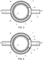
- a separating member 22 of porous material is arranged inside the evaporator device 12, between the inner wall 14 and the outer wall 16, so as to divide radially the cavity 20 into an inner cavity 20a, extending between the inner wall 14 and the separating member 22, and an outer cavity 20b, extending between the separating member 22 and the outer wall 16.
- the separating member 22 extends over the entire length (axial dimension) of the cavity 20, while it is interrupted in the circumferential direction so as to connect the inner cavity 20a and the outer cavity 20b with each other in a zone of the cavity 20 indicated 20c ( Figure 3 ).
- the separating member 22 is therefore formed as a tubular element with an axial slit (i.e. a slit extending parallel to its axis, coinciding with the axis of the casing of the evaporator device 12).
- the heat recovery system further comprises a conduit 24 which is connected at its opposite ends to the evaporator device 12 so as to form with the latter a closed circuit which is filled with a two-phase fluid (such as water, ammonia or propylene). More specifically, the conduit 24 is connected to the evaporator device 12 on one side in the zone 20c of the cavity 20 and on the other side along the outer cavity 20b, preferably on the diametrically opposite side to the zone 20c.
- a two-phase fluid such as water, ammonia or propylene
- the heat recovery system operates as follows.
- the fluid in liquid phase which is inside the inner cavity 20a of the evaporator device 12 receives heat from the hot air flowing along the tube 10 and evaporates.
- the fluid in vapour phase flows out of the evaporator device 12 in the zone 20c of the cavity 20 (as indicated by the arrow OUT in Figures 2 and 3 ) and along the conduit 24 to transfer heat to one or more user appliances served by the heat recovery system.
- the recovered heat may be used, for example, for heating the fuel or for de-icing purposes, i.e. for heating parts of the aircraft, such as in particular the wings, where formation of ice must be avoided.
- the fluid then returns in liquid form to the evaporator device 12, namely to the region of the outer cavity 20b (as indicated by the arrow IN in Figures 2 and 3 ) and from here is pushed radially by capillarity through the separating member 22 into the inner cavity 20a, where transition from liquid phase to vapour phase again occurs owing to the heat released by the hot air which flows along the tube 10.
- a continuous fluid flow is thus established along the conduit 24, which allows the heat extracted from the hot air flowing in the tube 10 to be transferred wherever required, for example to the fuel tanks or to the wings of the aircraft.
- the inner cavity 20a and the outer cavity 20b are not connected with each other in the zone 20c of the cavity 20, but communicate with each other only via the pores of the separating member 22.
- the separating member 22 is interrupted in the circumferential direction (i.e. is formed in the manner of a tubular sleeve having an axial slit) so as to put the inner cavity 20a into communication with the conduit 24.
- the heat recovery system will advantageously comprise at least one evaporator device arranged on each of the hot air tubes.
Landscapes
- Engineering & Computer Science (AREA)
- General Engineering & Computer Science (AREA)
- Physics & Mathematics (AREA)
- Thermal Sciences (AREA)
- Sustainable Development (AREA)
- Mechanical Engineering (AREA)
- Life Sciences & Earth Sciences (AREA)
- Health & Medical Sciences (AREA)
- General Health & Medical Sciences (AREA)
- Pulmonology (AREA)
- Aviation & Aerospace Engineering (AREA)
- Heat-Exchange Devices With Radiators And Conduit Assemblies (AREA)
- Engine Equipment That Uses Special Cycles (AREA)
Applications Claiming Priority (1)
| Application Number | Priority Date | Filing Date | Title |
|---|---|---|---|
| ITUB2015A000833A ITUB20150833A1 (it) | 2015-05-21 | 2015-05-21 | Sistema di recupero del calore, particolarmente per impiego su velivolo, utilizzante un circuito a fluido bifase. |
Publications (2)
| Publication Number | Publication Date |
|---|---|
| EP3095704A1 true EP3095704A1 (de) | 2016-11-23 |
| EP3095704B1 EP3095704B1 (de) | 2018-05-23 |
Family
ID=54064430
Family Applications (1)
| Application Number | Title | Priority Date | Filing Date |
|---|---|---|---|
| EP16170051.3A Active EP3095704B1 (de) | 2015-05-21 | 2016-05-18 | Wärmerückgewinnungssystem, insbesondere zur verwendung in einem flugzeug, mit einem zweiphasigen flüssigkeitskreislauf |
Country Status (4)
| Country | Link |
|---|---|
| US (1) | US10029800B2 (de) |
| EP (1) | EP3095704B1 (de) |
| ES (1) | ES2684673T3 (de) |
| IT (1) | ITUB20150833A1 (de) |
Cited By (1)
| Publication number | Priority date | Publication date | Assignee | Title |
|---|---|---|---|---|
| US20190142348A1 (en) * | 2017-11-16 | 2019-05-16 | Foreaider Co., Ltd. | Smart pad and system thereof |
Families Citing this family (1)
| Publication number | Priority date | Publication date | Assignee | Title |
|---|---|---|---|---|
| EP3674559B1 (de) * | 2018-12-24 | 2021-06-02 | LEONARDO S.p.A. | Strahllüfter und fahrzeug mit einem solchen lüfter |
Citations (7)
| Publication number | Priority date | Publication date | Assignee | Title |
|---|---|---|---|---|
| US4516631A (en) | 1981-11-04 | 1985-05-14 | Combustion Engineering, Inc. | Nozzle cooled by heat pipe means |
| EP0469825A2 (de) * | 1990-07-30 | 1992-02-05 | General Electric Company | Vorkühlungswärmetauscher, integriert mit stromlinienförmiger Befestigungsvorrichtung einer Gasturbine |
| CA2217972A1 (en) * | 1997-10-09 | 1999-04-09 | Gary Proskiw | Greywater heat recovery device using a combined thermosyphon/heat pipe principle |
| US20060185825A1 (en) * | 2003-07-23 | 2006-08-24 | Wei Chen | Loop type thermo syphone, heat radiation system, heat exchange system, and stirling cooling chamber |
| CN101590913A (zh) * | 2009-07-02 | 2009-12-02 | 北京航空航天大学 | 采用环路热管的民机防冰除冰方法 |
| WO2014102402A1 (es) * | 2012-12-28 | 2014-07-03 | Ibérica Del Espacio, S.A. | Aparato de caloducto en bucle cerrado para transmisión de calor y control térmico |
| EP2792437A1 (de) * | 2013-04-16 | 2014-10-22 | Benteler Automobiltechnik GmbH | Verfahren zum Herstellen eines Verdampferrohres |
Family Cites Families (3)
| Publication number | Priority date | Publication date | Assignee | Title |
|---|---|---|---|---|
| US20120168111A1 (en) * | 2009-09-25 | 2012-07-05 | Dow Global Technologies Inc. | Heat transfer system utilizing thermal energy storage materials |
| US11788797B2 (en) * | 2012-07-18 | 2023-10-17 | University Of Virginia Patent Foundation | Heat transfer device for high heat flux applications and related methods thereof |
| US9951659B2 (en) * | 2015-01-23 | 2018-04-24 | Ford Global Technologies, Llc | Thermodynamic system in a vehicle |
-
2015
- 2015-05-21 IT ITUB2015A000833A patent/ITUB20150833A1/it unknown
-
2016
- 2016-05-18 ES ES16170051.3T patent/ES2684673T3/es active Active
- 2016-05-18 EP EP16170051.3A patent/EP3095704B1/de active Active
- 2016-05-19 US US15/159,605 patent/US10029800B2/en active Active
Patent Citations (7)
| Publication number | Priority date | Publication date | Assignee | Title |
|---|---|---|---|---|
| US4516631A (en) | 1981-11-04 | 1985-05-14 | Combustion Engineering, Inc. | Nozzle cooled by heat pipe means |
| EP0469825A2 (de) * | 1990-07-30 | 1992-02-05 | General Electric Company | Vorkühlungswärmetauscher, integriert mit stromlinienförmiger Befestigungsvorrichtung einer Gasturbine |
| CA2217972A1 (en) * | 1997-10-09 | 1999-04-09 | Gary Proskiw | Greywater heat recovery device using a combined thermosyphon/heat pipe principle |
| US20060185825A1 (en) * | 2003-07-23 | 2006-08-24 | Wei Chen | Loop type thermo syphone, heat radiation system, heat exchange system, and stirling cooling chamber |
| CN101590913A (zh) * | 2009-07-02 | 2009-12-02 | 北京航空航天大学 | 采用环路热管的民机防冰除冰方法 |
| WO2014102402A1 (es) * | 2012-12-28 | 2014-07-03 | Ibérica Del Espacio, S.A. | Aparato de caloducto en bucle cerrado para transmisión de calor y control térmico |
| EP2792437A1 (de) * | 2013-04-16 | 2014-10-22 | Benteler Automobiltechnik GmbH | Verfahren zum Herstellen eines Verdampferrohres |
Cited By (2)
| Publication number | Priority date | Publication date | Assignee | Title |
|---|---|---|---|---|
| US20190142348A1 (en) * | 2017-11-16 | 2019-05-16 | Foreaider Co., Ltd. | Smart pad and system thereof |
| US11471110B2 (en) * | 2017-11-16 | 2022-10-18 | Foreaider Co., Ltd. | Smart pad and system thereof |
Also Published As
| Publication number | Publication date |
|---|---|
| ITUB20150833A1 (it) | 2016-11-21 |
| EP3095704B1 (de) | 2018-05-23 |
| ES2684673T3 (es) | 2018-10-04 |
| US20160340047A1 (en) | 2016-11-24 |
| US10029800B2 (en) | 2018-07-24 |
Similar Documents
| Publication | Publication Date | Title |
|---|---|---|
| CN103786886B (zh) | 一种用于飞机机翼的防除冰系统 | |
| RU2449143C2 (ru) | Теплопередающая система для газотурбинного двигателя | |
| US9664451B2 (en) | Co-fired absorption system generator | |
| CN103344143B (zh) | 一种环路热管用蒸发器和储液器及其应用 | |
| US20190331432A1 (en) | Loop heat pipe having condensation segment partially filled with wick | |
| EP2606306B1 (de) | Wärmeübertragungssystem | |
| EP3183514B1 (de) | Kühlsystem | |
| JP6125235B2 (ja) | 燃料電池の熱電併給システム | |
| US20140138058A1 (en) | Heat pipe having a channeled heat transfer array | |
| US20180229850A1 (en) | Anti-icing system for gas turbine engine | |
| CN108286911B (zh) | 低温回路热管 | |
| EP3095704B1 (de) | Wärmerückgewinnungssystem, insbesondere zur verwendung in einem flugzeug, mit einem zweiphasigen flüssigkeitskreislauf | |
| CN105599906A (zh) | 采用回路型热管的航空发动机整流帽罩防冰装置及方法 | |
| US20160146542A1 (en) | Shell and tube heat exchanger | |
| CN205448428U (zh) | 一种带热交换功能的气液分离器及空调系统 | |
| US10294967B2 (en) | Systems and methods for heat balance and transport for aircraft hydraulic systems | |
| US10717535B2 (en) | Two-phase type heat transfer device for heat sources operating at a wide temperature range | |
| CN103334985A (zh) | 一种液压油降温油箱 | |
| CN208398693U (zh) | 微通道阵列辅助驱动的回路热管 | |
| Van Oost et al. | Secondary wick operation principle and performance mapping in LHP and FLHP evaporators | |
| CN204987981U (zh) | 多级传导真空相变加热管 | |
| WO2010077180A2 (ru) | Устройство для отвода тепла от тепловыделяющих систем (варианты) | |
| CN207455911U (zh) | 一种热泵热水器 | |
| EP3943831A1 (de) | Bi-funktioneller wassererhitzer | |
| CN105333613B (zh) | 一种热水器和冷凝器 |
Legal Events
| Date | Code | Title | Description |
|---|---|---|---|
| PUAI | Public reference made under article 153(3) epc to a published international application that has entered the european phase |
Free format text: ORIGINAL CODE: 0009012 |
|
| AK | Designated contracting states |
Kind code of ref document: A1 Designated state(s): AL AT BE BG CH CY CZ DE DK EE ES FI FR GB GR HR HU IE IS IT LI LT LU LV MC MK MT NL NO PL PT RO RS SE SI SK SM TR |
|
| AX | Request for extension of the european patent |
Extension state: BA ME |
|
| STAA | Information on the status of an ep patent application or granted ep patent |
Free format text: STATUS: REQUEST FOR EXAMINATION WAS MADE |
|
| 17P | Request for examination filed |
Effective date: 20170519 |
|
| RBV | Designated contracting states (corrected) |
Designated state(s): AL AT BE BG CH CY CZ DE DK EE ES FI FR GB GR HR HU IE IS IT LI LT LU LV MC MK MT NL NO PL PT RO RS SE SI SK SM TR |
|
| GRAP | Despatch of communication of intention to grant a patent |
Free format text: ORIGINAL CODE: EPIDOSNIGR1 |
|
| RIC1 | Information provided on ipc code assigned before grant |
Ipc: B64D 37/34 20060101ALN20171006BHEP Ipc: F28D 15/02 20060101ALI20171006BHEP Ipc: B64D 15/02 20060101ALN20171006BHEP Ipc: B64D 13/08 20060101AFI20171006BHEP |
|
| STAA | Information on the status of an ep patent application or granted ep patent |
Free format text: STATUS: GRANT OF PATENT IS INTENDED |
|
| INTG | Intention to grant announced |
Effective date: 20171116 |
|
| GRAS | Grant fee paid |
Free format text: ORIGINAL CODE: EPIDOSNIGR3 |
|
| GRAA | (expected) grant |
Free format text: ORIGINAL CODE: 0009210 |
|
| STAA | Information on the status of an ep patent application or granted ep patent |
Free format text: STATUS: THE PATENT HAS BEEN GRANTED |
|
| RAP1 | Party data changed (applicant data changed or rights of an application transferred) |
Owner name: LEONARDO S.P.A. |
|
| AK | Designated contracting states |
Kind code of ref document: B1 Designated state(s): AL AT BE BG CH CY CZ DE DK EE ES FI FR GB GR HR HU IE IS IT LI LT LU LV MC MK MT NL NO PL PT RO RS SE SI SK SM TR |
|
| REG | Reference to a national code |
Ref country code: GB Ref legal event code: FG4D |
|
| REG | Reference to a national code |
Ref country code: CH Ref legal event code: EP |
|
| REG | Reference to a national code |
Ref country code: IE Ref legal event code: FG4D |
|
| REG | Reference to a national code |
Ref country code: AT Ref legal event code: REF Ref document number: 1001328 Country of ref document: AT Kind code of ref document: T Effective date: 20180615 |
|
| REG | Reference to a national code |
Ref country code: DE Ref legal event code: R096 Ref document number: 602016003162 Country of ref document: DE |
|
| REG | Reference to a national code |
Ref country code: SE Ref legal event code: TRGR |
|
| REG | Reference to a national code |
Ref country code: NL Ref legal event code: MP Effective date: 20180523 |
|
| REG | Reference to a national code |
Ref country code: ES Ref legal event code: FG2A Ref document number: 2684673 Country of ref document: ES Kind code of ref document: T3 Effective date: 20181004 |
|
| REG | Reference to a national code |
Ref country code: LT Ref legal event code: MG4D |
|
| PG25 | Lapsed in a contracting state [announced via postgrant information from national office to epo] |
Ref country code: LT Free format text: LAPSE BECAUSE OF FAILURE TO SUBMIT A TRANSLATION OF THE DESCRIPTION OR TO PAY THE FEE WITHIN THE PRESCRIBED TIME-LIMIT Effective date: 20180523 Ref country code: NO Free format text: LAPSE BECAUSE OF FAILURE TO SUBMIT A TRANSLATION OF THE DESCRIPTION OR TO PAY THE FEE WITHIN THE PRESCRIBED TIME-LIMIT Effective date: 20180823 Ref country code: FI Free format text: LAPSE BECAUSE OF FAILURE TO SUBMIT A TRANSLATION OF THE DESCRIPTION OR TO PAY THE FEE WITHIN THE PRESCRIBED TIME-LIMIT Effective date: 20180523 Ref country code: BG Free format text: LAPSE BECAUSE OF FAILURE TO SUBMIT A TRANSLATION OF THE DESCRIPTION OR TO PAY THE FEE WITHIN THE PRESCRIBED TIME-LIMIT Effective date: 20180823 |
|
| PG25 | Lapsed in a contracting state [announced via postgrant information from national office to epo] |
Ref country code: LV Free format text: LAPSE BECAUSE OF FAILURE TO SUBMIT A TRANSLATION OF THE DESCRIPTION OR TO PAY THE FEE WITHIN THE PRESCRIBED TIME-LIMIT Effective date: 20180523 Ref country code: RS Free format text: LAPSE BECAUSE OF FAILURE TO SUBMIT A TRANSLATION OF THE DESCRIPTION OR TO PAY THE FEE WITHIN THE PRESCRIBED TIME-LIMIT Effective date: 20180523 Ref country code: NL Free format text: LAPSE BECAUSE OF FAILURE TO SUBMIT A TRANSLATION OF THE DESCRIPTION OR TO PAY THE FEE WITHIN THE PRESCRIBED TIME-LIMIT Effective date: 20180523 Ref country code: GR Free format text: LAPSE BECAUSE OF FAILURE TO SUBMIT A TRANSLATION OF THE DESCRIPTION OR TO PAY THE FEE WITHIN THE PRESCRIBED TIME-LIMIT Effective date: 20180824 Ref country code: HR Free format text: LAPSE BECAUSE OF FAILURE TO SUBMIT A TRANSLATION OF THE DESCRIPTION OR TO PAY THE FEE WITHIN THE PRESCRIBED TIME-LIMIT Effective date: 20180523 |
|
| REG | Reference to a national code |
Ref country code: AT Ref legal event code: MK05 Ref document number: 1001328 Country of ref document: AT Kind code of ref document: T Effective date: 20180523 |
|
| PG25 | Lapsed in a contracting state [announced via postgrant information from national office to epo] |
Ref country code: PL Free format text: LAPSE BECAUSE OF FAILURE TO SUBMIT A TRANSLATION OF THE DESCRIPTION OR TO PAY THE FEE WITHIN THE PRESCRIBED TIME-LIMIT Effective date: 20180523 Ref country code: DK Free format text: LAPSE BECAUSE OF FAILURE TO SUBMIT A TRANSLATION OF THE DESCRIPTION OR TO PAY THE FEE WITHIN THE PRESCRIBED TIME-LIMIT Effective date: 20180523 Ref country code: EE Free format text: LAPSE BECAUSE OF FAILURE TO SUBMIT A TRANSLATION OF THE DESCRIPTION OR TO PAY THE FEE WITHIN THE PRESCRIBED TIME-LIMIT Effective date: 20180523 Ref country code: AT Free format text: LAPSE BECAUSE OF FAILURE TO SUBMIT A TRANSLATION OF THE DESCRIPTION OR TO PAY THE FEE WITHIN THE PRESCRIBED TIME-LIMIT Effective date: 20180523 Ref country code: CZ Free format text: LAPSE BECAUSE OF FAILURE TO SUBMIT A TRANSLATION OF THE DESCRIPTION OR TO PAY THE FEE WITHIN THE PRESCRIBED TIME-LIMIT Effective date: 20180523 Ref country code: SK Free format text: LAPSE BECAUSE OF FAILURE TO SUBMIT A TRANSLATION OF THE DESCRIPTION OR TO PAY THE FEE WITHIN THE PRESCRIBED TIME-LIMIT Effective date: 20180523 Ref country code: RO Free format text: LAPSE BECAUSE OF FAILURE TO SUBMIT A TRANSLATION OF THE DESCRIPTION OR TO PAY THE FEE WITHIN THE PRESCRIBED TIME-LIMIT Effective date: 20180523 |
|
| REG | Reference to a national code |
Ref country code: DE Ref legal event code: R097 Ref document number: 602016003162 Country of ref document: DE |
|
| PG25 | Lapsed in a contracting state [announced via postgrant information from national office to epo] |
Ref country code: SM Free format text: LAPSE BECAUSE OF FAILURE TO SUBMIT A TRANSLATION OF THE DESCRIPTION OR TO PAY THE FEE WITHIN THE PRESCRIBED TIME-LIMIT Effective date: 20180523 Ref country code: IT Free format text: LAPSE BECAUSE OF FAILURE TO SUBMIT A TRANSLATION OF THE DESCRIPTION OR TO PAY THE FEE WITHIN THE PRESCRIBED TIME-LIMIT Effective date: 20180523 |
|
| PLBE | No opposition filed within time limit |
Free format text: ORIGINAL CODE: 0009261 |
|
| STAA | Information on the status of an ep patent application or granted ep patent |
Free format text: STATUS: NO OPPOSITION FILED WITHIN TIME LIMIT |
|
| 26N | No opposition filed |
Effective date: 20190226 |
|
| PG25 | Lapsed in a contracting state [announced via postgrant information from national office to epo] |
Ref country code: SI Free format text: LAPSE BECAUSE OF FAILURE TO SUBMIT A TRANSLATION OF THE DESCRIPTION OR TO PAY THE FEE WITHIN THE PRESCRIBED TIME-LIMIT Effective date: 20180523 |
|
| PGFP | Annual fee paid to national office [announced via postgrant information from national office to epo] |
Ref country code: ES Payment date: 20190603 Year of fee payment: 4 |
|
| PGFP | Annual fee paid to national office [announced via postgrant information from national office to epo] |
Ref country code: SE Payment date: 20190516 Year of fee payment: 4 |
|
| PG25 | Lapsed in a contracting state [announced via postgrant information from national office to epo] |
Ref country code: AL Free format text: LAPSE BECAUSE OF FAILURE TO SUBMIT A TRANSLATION OF THE DESCRIPTION OR TO PAY THE FEE WITHIN THE PRESCRIBED TIME-LIMIT Effective date: 20180523 |
|
| REG | Reference to a national code |
Ref country code: CH Ref legal event code: PL |
|
| PG25 | Lapsed in a contracting state [announced via postgrant information from national office to epo] |
Ref country code: CH Free format text: LAPSE BECAUSE OF NON-PAYMENT OF DUE FEES Effective date: 20190531 Ref country code: MC Free format text: LAPSE BECAUSE OF FAILURE TO SUBMIT A TRANSLATION OF THE DESCRIPTION OR TO PAY THE FEE WITHIN THE PRESCRIBED TIME-LIMIT Effective date: 20180523 Ref country code: LI Free format text: LAPSE BECAUSE OF NON-PAYMENT OF DUE FEES Effective date: 20190531 |
|
| REG | Reference to a national code |
Ref country code: BE Ref legal event code: MM Effective date: 20190531 |
|
| PG25 | Lapsed in a contracting state [announced via postgrant information from national office to epo] |
Ref country code: LU Free format text: LAPSE BECAUSE OF NON-PAYMENT OF DUE FEES Effective date: 20190518 |
|
| PG25 | Lapsed in a contracting state [announced via postgrant information from national office to epo] |
Ref country code: TR Free format text: LAPSE BECAUSE OF FAILURE TO SUBMIT A TRANSLATION OF THE DESCRIPTION OR TO PAY THE FEE WITHIN THE PRESCRIBED TIME-LIMIT Effective date: 20180523 |
|
| PG25 | Lapsed in a contracting state [announced via postgrant information from national office to epo] |
Ref country code: IE Free format text: LAPSE BECAUSE OF NON-PAYMENT OF DUE FEES Effective date: 20190518 |
|
| PG25 | Lapsed in a contracting state [announced via postgrant information from national office to epo] |
Ref country code: BE Free format text: LAPSE BECAUSE OF NON-PAYMENT OF DUE FEES Effective date: 20190531 |
|
| PG25 | Lapsed in a contracting state [announced via postgrant information from national office to epo] |
Ref country code: PT Free format text: LAPSE BECAUSE OF FAILURE TO SUBMIT A TRANSLATION OF THE DESCRIPTION OR TO PAY THE FEE WITHIN THE PRESCRIBED TIME-LIMIT Effective date: 20180924 |
|
| PG25 | Lapsed in a contracting state [announced via postgrant information from national office to epo] |
Ref country code: SE Free format text: LAPSE BECAUSE OF NON-PAYMENT OF DUE FEES Effective date: 20200519 |
|
| GBPC | Gb: european patent ceased through non-payment of renewal fee |
Effective date: 20200518 |
|
| PG25 | Lapsed in a contracting state [announced via postgrant information from national office to epo] |
Ref country code: GB Free format text: LAPSE BECAUSE OF NON-PAYMENT OF DUE FEES Effective date: 20200518 |
|
| PG25 | Lapsed in a contracting state [announced via postgrant information from national office to epo] |
Ref country code: CY Free format text: LAPSE BECAUSE OF FAILURE TO SUBMIT A TRANSLATION OF THE DESCRIPTION OR TO PAY THE FEE WITHIN THE PRESCRIBED TIME-LIMIT Effective date: 20180523 |
|
| PG25 | Lapsed in a contracting state [announced via postgrant information from national office to epo] |
Ref country code: IS Free format text: LAPSE BECAUSE OF FAILURE TO SUBMIT A TRANSLATION OF THE DESCRIPTION OR TO PAY THE FEE WITHIN THE PRESCRIBED TIME-LIMIT Effective date: 20180923 |
|
| PG25 | Lapsed in a contracting state [announced via postgrant information from national office to epo] |
Ref country code: MT Free format text: LAPSE BECAUSE OF FAILURE TO SUBMIT A TRANSLATION OF THE DESCRIPTION OR TO PAY THE FEE WITHIN THE PRESCRIBED TIME-LIMIT Effective date: 20180523 Ref country code: HU Free format text: LAPSE BECAUSE OF FAILURE TO SUBMIT A TRANSLATION OF THE DESCRIPTION OR TO PAY THE FEE WITHIN THE PRESCRIBED TIME-LIMIT; INVALID AB INITIO Effective date: 20160518 |
|
| REG | Reference to a national code |
Ref country code: ES Ref legal event code: FD2A Effective date: 20210927 |
|
| PG25 | Lapsed in a contracting state [announced via postgrant information from national office to epo] |
Ref country code: ES Free format text: LAPSE BECAUSE OF NON-PAYMENT OF DUE FEES Effective date: 20200519 |
|
| PG25 | Lapsed in a contracting state [announced via postgrant information from national office to epo] |
Ref country code: MK Free format text: LAPSE BECAUSE OF FAILURE TO SUBMIT A TRANSLATION OF THE DESCRIPTION OR TO PAY THE FEE WITHIN THE PRESCRIBED TIME-LIMIT Effective date: 20180523 |
|
| REG | Reference to a national code |
Ref country code: DE Ref legal event code: R082 Ref document number: 602016003162 Country of ref document: DE Representative=s name: ALPSPITZ IP ALLGAYER UND PARTNER PATENTANWAELT, DE |
|
| PGFP | Annual fee paid to national office [announced via postgrant information from national office to epo] |
Ref country code: DE Payment date: 20250523 Year of fee payment: 10 |
|
| PGFP | Annual fee paid to national office [announced via postgrant information from national office to epo] |
Ref country code: FR Payment date: 20250430 Year of fee payment: 10 |