EP2791953B1 - Circuit breaker, circuit breaker terminal lug cover, and method of protecting a terminal lug - Google Patents
Circuit breaker, circuit breaker terminal lug cover, and method of protecting a terminal lug Download PDFInfo
- Publication number
- EP2791953B1 EP2791953B1 EP12798517.4A EP12798517A EP2791953B1 EP 2791953 B1 EP2791953 B1 EP 2791953B1 EP 12798517 A EP12798517 A EP 12798517A EP 2791953 B1 EP2791953 B1 EP 2791953B1
- Authority
- EP
- European Patent Office
- Prior art keywords
- terminal lug
- circuit breaker
- cover
- terminal
- sides
- Prior art date
- Legal status (The legal status is an assumption and is not a legal conclusion. Google has not performed a legal analysis and makes no representation as to the accuracy of the status listed.)
- Active
Links
- 238000000034 method Methods 0.000 title claims description 11
- 239000007789 gas Substances 0.000 claims description 15
- 230000007797 corrosion Effects 0.000 claims description 12
- 238000005260 corrosion Methods 0.000 claims description 12
- 230000015556 catabolic process Effects 0.000 claims description 7
- 238000006731 degradation reaction Methods 0.000 claims description 7
- 230000008878 coupling Effects 0.000 claims 5
- 238000010168 coupling process Methods 0.000 claims 5
- 238000005859 coupling reaction Methods 0.000 claims 5
- 239000000463 material Substances 0.000 description 6
- 239000004020 conductor Substances 0.000 description 5
- 230000006872 improvement Effects 0.000 description 3
- 239000003063 flame retardant Substances 0.000 description 2
- 238000012986 modification Methods 0.000 description 2
- 230000004048 modification Effects 0.000 description 2
- RYGMFSIKBFXOCR-UHFFFAOYSA-N Copper Chemical compound [Cu] RYGMFSIKBFXOCR-UHFFFAOYSA-N 0.000 description 1
- 229920004142 LEXAN™ Polymers 0.000 description 1
- 239000004418 Lexan Substances 0.000 description 1
- XAGFODPZIPBFFR-UHFFFAOYSA-N aluminium Chemical compound [Al] XAGFODPZIPBFFR-UHFFFAOYSA-N 0.000 description 1
- 229910052782 aluminium Inorganic materials 0.000 description 1
- 230000000712 assembly Effects 0.000 description 1
- 238000000429 assembly Methods 0.000 description 1
- 230000008859 change Effects 0.000 description 1
- 229910052802 copper Inorganic materials 0.000 description 1
- 239000010949 copper Substances 0.000 description 1
- 230000003628 erosive effect Effects 0.000 description 1
- 239000011521 glass Substances 0.000 description 1
- 238000009413 insulation Methods 0.000 description 1
- 238000012423 maintenance Methods 0.000 description 1
- 230000007246 mechanism Effects 0.000 description 1
- 239000000155 melt Substances 0.000 description 1
- 238000002844 melting Methods 0.000 description 1
- 230000008018 melting Effects 0.000 description 1
- 238000009877 rendering Methods 0.000 description 1
- 230000008439 repair process Effects 0.000 description 1
- 239000007787 solid Substances 0.000 description 1
- 239000012815 thermoplastic material Substances 0.000 description 1
- -1 without limitation Substances 0.000 description 1
Images

Classifications
-
- H—ELECTRICITY
- H01—ELECTRIC ELEMENTS
- H01H—ELECTRIC SWITCHES; RELAYS; SELECTORS; EMERGENCY PROTECTIVE DEVICES
- H01H77/00—Protective overload circuit-breaking switches operated by excess current and requiring separate action for resetting
-
- H—ELECTRICITY
- H01—ELECTRIC ELEMENTS
- H01H—ELECTRIC SWITCHES; RELAYS; SELECTORS; EMERGENCY PROTECTIVE DEVICES
- H01H9/00—Details of switching devices, not covered by groups H01H1/00 - H01H7/00
- H01H9/02—Bases, casings, or covers
- H01H9/0264—Protective covers for terminals
-
- H—ELECTRICITY
- H01—ELECTRIC ELEMENTS
- H01H—ELECTRIC SWITCHES; RELAYS; SELECTORS; EMERGENCY PROTECTIVE DEVICES
- H01H69/00—Apparatus or processes for the manufacture of emergency protective devices
-
- H—ELECTRICITY
- H01—ELECTRIC ELEMENTS
- H01H—ELECTRIC SWITCHES; RELAYS; SELECTORS; EMERGENCY PROTECTIVE DEVICES
- H01H71/00—Details of the protective switches or relays covered by groups H01H73/00 - H01H83/00
- H01H71/08—Terminals; Connections
-
- H—ELECTRICITY
- H01—ELECTRIC ELEMENTS
- H01R—ELECTRICALLY-CONDUCTIVE CONNECTIONS; STRUCTURAL ASSOCIATIONS OF A PLURALITY OF MUTUALLY-INSULATED ELECTRICAL CONNECTING ELEMENTS; COUPLING DEVICES; CURRENT COLLECTORS
- H01R13/00—Details of coupling devices of the kinds covered by groups H01R12/70 or H01R24/00 - H01R33/00
- H01R13/46—Bases; Cases
- H01R13/533—Bases, cases made for use in extreme conditions, e.g. high temperature, radiation, vibration, corrosive environment, pressure
-
- Y—GENERAL TAGGING OF NEW TECHNOLOGICAL DEVELOPMENTS; GENERAL TAGGING OF CROSS-SECTIONAL TECHNOLOGIES SPANNING OVER SEVERAL SECTIONS OF THE IPC; TECHNICAL SUBJECTS COVERED BY FORMER USPC CROSS-REFERENCE ART COLLECTIONS [XRACs] AND DIGESTS
- Y10—TECHNICAL SUBJECTS COVERED BY FORMER USPC
- Y10T—TECHNICAL SUBJECTS COVERED BY FORMER US CLASSIFICATION
- Y10T29/00—Metal working
- Y10T29/49—Method of mechanical manufacture
- Y10T29/49002—Electrical device making
- Y10T29/49105—Switch making
Definitions
- the disclosed concept pertains generally to heat and corrosion protection devices and, more particularly, to devices used to protect circuit breaker terminals, terminal screw threads, connecting cables, and the like, from heat and corrosion caused by high temperature gases.
- the disclosed concept further pertains to circuit breakers.
- the disclosed concept also pertains to methods of protecting circuit breaker terminals, terminal screw threads, connecting cables, and the like.
- a circuit breaker apparatus as it is defined in the pre-characterizing portion of claim 1 is shown in US 2005/057333 A1 .
- Circuit breakers function to interrupt the flow of electric current when an overload or short circuit is detected within a power circuit.
- an arc is generated, which creates exhaust gases of high temperature.
- These ionized exhaust gases can damage the terminal lug of the circuit breaker by causing corrosion.
- the heated exhaust gases can damage the circuit breaker terminal lug by causing connecting cables to melt onto the terminal lug. Corrosion of the terminal lug coupled with melted cable material can damage terminal lug screw threads rendering the threads and terminal lug unusable.
- terminal shields lie between the internal phases of a circuit breaker and protect each phase from the arc of another phase. It is believed that such terminal shields fail to properly address or protect external circuit breaker terminal lugs and connecting cables from such arcing events.
- circuit breaker terminal lug cover protects a circuit breaker terminal lug and a number of connecting cables from degradation or corrosion (e.g., without limitation, caused by heat and/or ionized exhaust gasses).
- the present invention is a circuit breaker apparatus as it is defined in claim 1 and a method as it defined in claim 9.
- number shall mean one or an integer greater than one ( i . e ., a plurality).
- circuit breaker shall mean any electrical switch or circuit interrupter that interrupts the flow of electrical current in an electrical circuit upon the existence or occurrence of specified number of electrical/mechanical fault conditions, and that permits the flow of electric current in the electrical circuit under other conditions.
- circuit breaker terminal shall mean a component of a circuit breaker that permits a number of cables of a circuit to connect to the circuit breaker.
- circuit breaker terminal lug or "terminal lug” shall mean a physical component of a circuit breaker having a circuit breaker terminal.
- hole shall mean an opening through something; an area where something is missing; or an aperture through something.
- access hole shall mean a hole through or in something to access something else.
- screw shall mean a simple machine of the inclined plane type consisting of a spirally grooved solid cylinder structured to fit into a correspondingly grooved hollow cylinder; a nail-shaped or rod-shaped piece with a spiral groove structured to fit into a correspondingly grooved hallow material by rotating; or a threaded or spirally grooved fastener structured to fit into a correspondingly threaded or spirally grooved terminal lug by rotating.
- the term "cable” shall mean a circuit conductor having a number of individual electrical conductors.
- the disclosed concept provides advantageous apparatus and devices for protecting circuit breakers from failure, degradation, corrosion, and eventual replacement due to excessive heat resulting from ionized gases released during arcing events.
- the circuit breaker terminal lug covers described herein prolong the operational lifetime of circuit breakers, and their connecting components.
- thermal energy and/or ionized exhaust gasses are efficiently and effectively conducted away from or deflected away from the circuit breaker and its connecting cables.
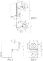
- Figure 1 shows an isometric view of one embodiment of an electrical circuit breaker 3, including a circuit breaker terminal lug 2 and a terminal lug cover 1.
- the electrical circuit breaker 3, a number of the circuit breaker terminal lugs 2 and a number of the terminal lug covers 1 form a circuit breaker apparatus 4.
- the example circuit breaker 3 includes six example circuit breaker terminals, although the disclosed concept is applicable to circuit breakers having any suitably number of circuit breaker terminals.
- terminals are on a top (with respect to Figure 1 ) portion of the circuit breaker 3, and three terminals are on a bottom (with respect to Figure 1 ) portion thereof
- Five of the circuit breaker terminals are shown as being assembled, having a terminal lug cover 1 shown affixed to a terminal lug 2.
- the terminal lugs 2 (only one is shown in Figure 1 , it being understood that each of the circuit breaker terminals, includes a terminal lug 2) and associated and respective terminal lug covers 1 are shown as assembled with the circuit breaker 3 in five of the six terminal assemblies of Figure 1 .
- a sixth terminal, assembly of Figure 1 shows the terminal lug 2 and the terminal lug cover 1 in exploded fashion, shown in an "unassembled" arrangement (i.e., unassembled from the circuit breaker 3).
- each terminal lug 2 includes a number of terminal lug screws 5 that are used to secure a number of circuit breaker cables (not shown) to each terminal lug 2.
- the terminal lug cover 1 includes an access hole 6 which allows for a screwdriver or similar tool (not shown) to tighten the number of terminal lug screws 5 to the number of cables (not shown).
- the terminal lug cover 1 includes a lower flange 7 and securing clips 8. The lower flange 7 and securing clips 8 are used in assembling and affixing the terminal lug cover 1 to the terminal lug 2.
- the terminal lug 2 can be made of copper, aluminum or any other suitably conductor for a circuit, such as a power circuit
- the terminal lug cover 1 can be made of a suitable thermoplastic material (e.g., without limitation, LEXAN ® 500 10% glass filled V0 rated).
- the terminal lug cover 1 advantageously couples to a portion of the terminal lug 2 external to the circuit breaker 3,
- the terminal lug 2 is removable from the circuit breaker 3.
- the upper (with respect to Figure 1 ) portion of the terminal lug 2 and the terminal lug cover 1 coupled thereto are both external to the circuit breaker 3.
- the terminal lug 2 electrically and mechanically connects to one of the line or load conductors (not shown) of the circuit breaker 4 via a terminal mounting screw (not shown).
- Figure 2 shows an exploded isometric view of the terminal lug 2 and the terminal lug cover 1.
- the terminal lug 2 includes two terminal lug screws 5 used to secure a number of cables (not shown) to each terminal
- the embodiment of Figure 2 further shows the terminal lug cover 1 including the securing clips 8.
- the securing clips 8 extend from a top (with respect to Figure 2 ) portion of the terminal lug cover 1.
- the terminal lug cover 1 includes the flange 7 extending therefrom.
- the access hole 6 is provided through the terminal lug cover 1 as shown in Figure 2 .
- the access hole 6 permits access to a number of the terminal lug screws 5, which are in turn used to couple cabling (not shown) to a respective circuit breaker terminal (not shown) positioned within the circuit breaker.
- Figure 3 shows a side profile view of the fully assembled terminal lug cover 1 mechanically coupled to and assembled to the terminal lug 2.
- a side profile of the terminal lug 2 is visible.
- the terminal lug cover 1 is snugly affixed to the terminal lug 2 via the top (with respect to Figure 3 ) securing clips 8 (only one securing clip 8 is shown in Figure 3 ).
- a profile view of the lower (with respect to Figure 3 ) flange 7 of the terminal lug cover 1 described above with reference to Figures 1 and 2 is shown in contact with a lower (with respect to Figure 3 ) half of the terminal lug 2.
- the terminal lug cover 1 fits snugly on a front side 16, a bottom side 17, and two opposing sides 18, 19 (shown in Figure 2 ) of the terminal lug 2 in order that physical contact between the terminal lug cover 1 and the terminal lug 2 permits the terminal lug cover I to conduct heat away from the terminal lug 2 and the number of cables (not shown) and/or deflect ionized gases away from the terminal lug 2.
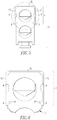
- Figure 4 is a front (with respect to Figures 1 and 4 ) profile view of the terminal lug cover 1 of Figures 1-3 shown mechanically affixed and assembled to the terminal lug 2 described above with reference to Figures 1-3
- the embodiment of the terminal lug cover 1 shown in Figure 4 comprises four sides 10,11,12,13, the securing claps 8 described above with reference to Figures 1-3 , the lower (with respect to Figure 4 ) flange 7, and the access hole 6 located on the front (with respect to Figure 4 ) side 10 of the terminal lug cover 1.
- the access hole 6 allows access to a number of the terminal lug screws 5 by a screwdriver or similar tool (not shown).
- the number of terminal lug screws 5 may be used to secure a number of connecting cables (not shown) to the terminal lug 2.
- Figure 5 shows a top (with respect to Figures 1 and 5 ) plan view of the terminal lug cover 1 affixed and assembled to the terminal lug 2 described above with reference to Figures 1-4 .
- Figures 3-5 three 10,12,13 of the four sides 10,11,12,13 of the terminal lug cover 1 are shown, affixed to the terminal lug 2.
- the securing clips 8 described above with reference to Figures 1-4 help secure the terminal lug cover 1 to the terminal lug 2.
- one embodiment of the terminal lug cover 1 also includes additional securing clips 9 that span the vertical (with respect to Figure 1 ) length of the rear (with respect to Figure 1 ) portion of the terminal lug cover 1.
- the additional securing clips 9 help to further secure and mechanically affix the terminal lug cover 1 to the terminal lug 2.
- the additional securing clips 9 interface with and couple to a chamfered edge 14 (a top portion of which is best shown in Figure 6 ) of the terminal lug 2 wherein the chamfered edge 14 is structured to mechanically couple to the additional securing clips 9.
- Figure 6 is a top (with respect to Figures 1 , 5 and 6 ) plan view of the terminal lug cover I affixed to the terminal lug 2 of Figure 5 , except magnified to show the terminal lug cover 1 in more detail.
- a top (with respect to Figure 1 ) portion of the terminal lug 2 is shown mechanically coupled to the terminal lug cover 1.
- Tree 10,12,13 of the four sides 10,11,12,13 of the terminal lug cover 1 are in view, as well as the securing clips 8 and additional securing clips 9.
- the disclosed terminal lug cover 1 protects the terminal lug 2 against relatively high temperature exhaust gasses after the circuit breaker 3 has interrupted the corresponding circuit (not shown).
- the terminal lug cover 1 protects against erosion of the terminal of the terminal lugs 2 from melted terminal material caused by high temperature gases exiting the circuit breaker 3. Since terminals and lug screw threads can otherwise bye damaged to a point where the cabling would need to be cut in order to change out the product, the disclosed solution can held avoid potentially costly repairs, beyond a simple circuit breaker replacement.
- the disclosed terminal lug cover 1 assembles to the profile of the circuit breaker terminal lug 2, with securing clips 8 and/or 9 to hold the cover in position.
- the cover 1 allows access to a number of the circuit breaker terminal lug screws 5 in order to connect cabling.
- the cover 1 then deflects ionized gases away from the body of the terminal lug 2.
- the embodiments of the assembly thus far described comprise the circuit breaker 3, the circuit breaker terminal lug 2, and the terminal lug cover 1.
- One embodiment of the disclosed concept utilizes a terminal lug cover, such as 1, having four sides 10,11,12,13 with the lower (with respect to Figure 1 ) flange 7 and the top (with respect to Figure 1 ) securing clips 8 as well as the rear (with respect to Figure 1 ) securing clips 9 and the circular hole 6 in the face allowing for the terminal lug screw 5 to pass through and connect to the terminal.
- the characteristics of the terminal lug cover 1 function to affix securely to the terminal lug 2 and carry heat away from the terminal lug 2 and connecting cables (not shown) through physical contact and/or function as a shield and deflect ionized gases away from the terminal lug 2.
- the gases deflect off of the shield, thereby preventing the heat of the gases from melting the terminal's material and the cable's insulation/conductor material.
- the material of the terminal lug cover 1 includes a suitable fire retardant component (e.g., without limitation, a V0 fire retardant component).
- One skilled in the art may find advantages by using a mechanism different than the securing clips 8 and/or 9 to fasten the terminal lug cover 1 to the terminal lugs 2.
- One skilled in the art may also find advantages by using a different type of hole than the circular hole 6 on the front (with respect to Figure 1 ) side 10 of the terminal lug cover 1 to permit the terminal lug screw 5 to pass through such cover.
- One skilled in the art may also find advantages by using more or fewer sides for the terminal lug cover 1.
- One skilled in the art may also find advantages by changing the shape and orientation of the flange 7 such that it may not exist at all, or in the alternative, may extend the full length of the lower (with respect to Figure 1 ) half of the terminal lug 2, while containing an additional access hole or terminal lug screw pass-through feature (not shown).
- the disclosed concept will extend the life of circuit breaker terminal lugs and connecting cables (not shown) by protecting against degradation and/or corrosion from heat, ionized exhaust gasses or connecting cable melt These advantageous characteristics of the terminal lug cover 1 will result in substantial cost savings in circuit breaker maintenance.
- circuit breaker terminal lug cover 1 What has been shown is the circuit breaker terminal lug cover 1. While the terminal lug cover 1 has been described through specific embodiments and applications thereof, it is understood that numerous modifications and variations could be made thereto by those skilled in the art without departing from the scope of the disclosed concept. It is therefore understood that within the scope of the claims, the disclosed concept may be practiced otherwise than specifically described herein.
- the disclosed concept is described in association with a molded case circuit breaker, although the disclosed concept is applicable to a wide range of circuit breakers.
Landscapes
- Engineering & Computer Science (AREA)
- Manufacturing & Machinery (AREA)
- Breakers (AREA)
- Connections Arranged To Contact A Plurality Of Conductors (AREA)
- Switch Cases, Indication, And Locking (AREA)
Applications Claiming Priority (2)
| Application Number | Priority Date | Filing Date | Title |
|---|---|---|---|
| US201161569726P | 2011-12-12 | 2011-12-12 | |
| PCT/US2012/065418 WO2013089966A1 (en) | 2011-12-12 | 2012-11-16 | Circuit breaker, circuit breaker terminal lug cover, and method of protecting a terminal lug |
Publications (2)
| Publication Number | Publication Date |
|---|---|
| EP2791953A1 EP2791953A1 (en) | 2014-10-22 |
| EP2791953B1 true EP2791953B1 (en) | 2017-03-29 |
Family
ID=47324418
Family Applications (1)
| Application Number | Title | Priority Date | Filing Date |
|---|---|---|---|
| EP12798517.4A Active EP2791953B1 (en) | 2011-12-12 | 2012-11-16 | Circuit breaker, circuit breaker terminal lug cover, and method of protecting a terminal lug |
Country Status (9)
| Country | Link |
|---|---|
| US (1) | US8853576B2 (enExample) |
| EP (1) | EP2791953B1 (enExample) |
| JP (1) | JP6116580B2 (enExample) |
| CN (1) | CN104025229B (enExample) |
| BR (1) | BR112014014059A2 (enExample) |
| CA (1) | CA2852506C (enExample) |
| IN (1) | IN2014KN00816A (enExample) |
| MX (1) | MX2014007214A (enExample) |
| WO (1) | WO2013089966A1 (enExample) |
Families Citing this family (10)
| Publication number | Priority date | Publication date | Assignee | Title |
|---|---|---|---|---|
| US9401251B2 (en) * | 2012-05-16 | 2016-07-26 | General Electric Company | Molded case circuit breaker |
| US9230766B2 (en) * | 2013-07-09 | 2016-01-05 | Eaton Coporation | Breaker secondary terminal block isolation chamber |
| US9299523B1 (en) * | 2014-12-12 | 2016-03-29 | Eaton Corporation | Switching device assembly and adapter assembly therefor |
| USD772175S1 (en) * | 2014-12-23 | 2016-11-22 | Eaton Corporation | Switch apparatus |
| US9842712B2 (en) | 2015-03-06 | 2017-12-12 | General Electric Company | Switching device having terminal cover, and method |
| US9905387B2 (en) | 2016-03-28 | 2018-02-27 | General Electric Company | Circuit breaker including end covers |
| USD796455S1 (en) * | 2016-06-15 | 2017-09-05 | Eaton Corporation | Electrical terminal |
| KR102055140B1 (ko) * | 2018-08-29 | 2019-12-12 | 엘에스산전 주식회사 | 배선용 차단기 |
| EP3772076B1 (en) * | 2019-08-02 | 2025-01-22 | ABB S.p.A. | Device for door and phase segregation in molded case circuit breakers |
| CN111710560B (zh) * | 2020-06-27 | 2025-04-08 | 天水二一三电器集团有限公司 | 一种多功能接触器防护罩 |
Family Cites Families (15)
| Publication number | Priority date | Publication date | Assignee | Title |
|---|---|---|---|---|
| DE2914507B1 (de) | 1979-04-10 | 1980-06-12 | Siemens Ag | Abdeckung fuer Anschluesse von elektrischen Geraeten |
| US4620076A (en) | 1985-03-27 | 1986-10-28 | Westinghouse Electric Corp. | Circuit breaker apparatus with line terminal shields |
| JPS6265750U (enExample) * | 1985-10-12 | 1987-04-23 | ||
| US4809132A (en) | 1987-10-23 | 1989-02-28 | General Electric Co. | Field installable line and load lug connectors for molded case circuit breakers |
| US5111008A (en) | 1990-09-13 | 1992-05-05 | Square D Company | Effective arc stack/efficient contact carrier |
| US5488337A (en) | 1993-08-05 | 1996-01-30 | Hubbard; Dean A. | Circuit breaker with distribution lug terminal having trapped insulator |
| DE9406404U1 (de) * | 1994-04-20 | 1994-06-23 | Moeller GmbH, 53115 Bonn | Elektrisches Schaltgerät mit Ausblaskanälen für Lichtbogengase |
| US6172586B1 (en) | 1999-11-05 | 2001-01-09 | Siemens Energy & Automation Inc. | Terminal barrier system for molded case circuit breaker |
| US6211759B1 (en) * | 2000-01-12 | 2001-04-03 | Eaton Corporation | Ionized gas deflector for a molded case circuit breaker |
| US6624375B2 (en) | 2001-04-04 | 2003-09-23 | Siemens Energy & Automation, Inc. | Wire lug/arc vent barrier molded case circuit breaker |
| US6930577B2 (en) | 2003-09-15 | 2005-08-16 | General Electric Company | Circuit breaker lug cover and gasket |
| US7750770B2 (en) * | 2006-09-25 | 2010-07-06 | Rockwell Automation Technologies, Inc. | Gas diverter for an electrical switching device |
| JP2008204863A (ja) * | 2007-02-21 | 2008-09-04 | Fuji Electric Fa Components & Systems Co Ltd | 電気機器の箱形端子装置 |
| KR100865288B1 (ko) * | 2007-04-03 | 2008-10-27 | 엘에스산전 주식회사 | 배선용 차단기의 모듈화 단자 및 이를 장착한 배선용차단기 |
| ITGE20070130A1 (it) * | 2007-12-28 | 2009-06-29 | Gewiss Spa | Morsetto perfezionato, particolarmente per interruttori automatici |
-
2012
- 2012-11-16 IN IN816KON2014 patent/IN2014KN00816A/en unknown
- 2012-11-16 WO PCT/US2012/065418 patent/WO2013089966A1/en not_active Ceased
- 2012-11-16 JP JP2014545918A patent/JP6116580B2/ja active Active
- 2012-11-16 US US13/678,785 patent/US8853576B2/en active Active
- 2012-11-16 MX MX2014007214A patent/MX2014007214A/es unknown
- 2012-11-16 CN CN201280060969.7A patent/CN104025229B/zh active Active
- 2012-11-16 EP EP12798517.4A patent/EP2791953B1/en active Active
- 2012-11-16 BR BR112014014059A patent/BR112014014059A2/pt not_active IP Right Cessation
- 2012-11-16 CA CA2852506A patent/CA2852506C/en not_active Expired - Fee Related
Non-Patent Citations (1)
| Title |
|---|
| None * |
Also Published As
| Publication number | Publication date |
|---|---|
| US20130146430A1 (en) | 2013-06-13 |
| JP6116580B2 (ja) | 2017-04-19 |
| US8853576B2 (en) | 2014-10-07 |
| CA2852506A1 (en) | 2013-06-20 |
| CN104025229A (zh) | 2014-09-03 |
| IN2014KN00816A (enExample) | 2015-10-02 |
| JP2015503206A (ja) | 2015-01-29 |
| WO2013089966A1 (en) | 2013-06-20 |
| CA2852506C (en) | 2019-05-14 |
| CN104025229B (zh) | 2017-06-30 |
| BR112014014059A2 (pt) | 2017-06-13 |
| EP2791953A1 (en) | 2014-10-22 |
| MX2014007214A (es) | 2014-11-14 |
Similar Documents
| Publication | Publication Date | Title |
|---|---|---|
| EP2791953B1 (en) | Circuit breaker, circuit breaker terminal lug cover, and method of protecting a terminal lug | |
| CA2980150C (en) | High voltage compact fuse assembly with magnetic arc deflection | |
| CN201540838U (zh) | 电气开关装置及其电弧隔板组件和电弧罩组件 | |
| US7586058B2 (en) | Electrical switching apparatus, and ARC hood assembly and chimney therefor | |
| EP3062403B1 (en) | Gas-insulated switchgear | |
| US7965485B2 (en) | Circuit protection device for photovoltaic systems | |
| US10224168B2 (en) | Fuse protector with a plurality of fuses | |
| US12244122B2 (en) | Arc mitigation apparatus and systems for panelboard applications | |
| US10636607B2 (en) | High voltage compact fused disconnect switch device with bi-directional magnetic arc deflection assembly | |
| US20160163491A1 (en) | Low profile fusible disconnect switch device | |
| CN212874379U (zh) | 用于低压断路器的端子夹具覆盖装置及对应的低压断路器 | |
| CN209626119U (zh) | 一种多用高压熔断器 | |
| CN222127247U (zh) | 一种高压开关柜内部熔丝夹子绝缘罩 | |
| CN218300269U (zh) | 一种新型断路器一体式组合导体 | |
| CN214477302U (zh) | 负荷断路开关 | |
| CN119315502A (zh) | 一种便于电涌保护模块二次焊接的浪涌保护器 | |
| CN110739185A (zh) | 一种小型断路器 | |
| MX2011008493A (es) | Centro de control de motores y ensamblaje de barras conectoras para el mismo. | |
| HK1225521B (en) | Gas-insulated switchgear | |
| HK1225521A1 (en) | Gas-insulated switchgear |
Legal Events
| Date | Code | Title | Description |
|---|---|---|---|
| PUAI | Public reference made under article 153(3) epc to a published international application that has entered the european phase |
Free format text: ORIGINAL CODE: 0009012 |
|
| 17P | Request for examination filed |
Effective date: 20140624 |
|
| AK | Designated contracting states |
Kind code of ref document: A1 Designated state(s): AL AT BE BG CH CY CZ DE DK EE ES FI FR GB GR HR HU IE IS IT LI LT LU LV MC MK MT NL NO PL PT RO RS SE SI SK SM TR |
|
| DAX | Request for extension of the european patent (deleted) | ||
| 17Q | First examination report despatched |
Effective date: 20160512 |
|
| GRAP | Despatch of communication of intention to grant a patent |
Free format text: ORIGINAL CODE: EPIDOSNIGR1 |
|
| INTG | Intention to grant announced |
Effective date: 20160927 |
|
| GRAS | Grant fee paid |
Free format text: ORIGINAL CODE: EPIDOSNIGR3 |
|
| GRAJ | Information related to disapproval of communication of intention to grant by the applicant or resumption of examination proceedings by the epo deleted |
Free format text: ORIGINAL CODE: EPIDOSDIGR1 |
|
| GRAL | Information related to payment of fee for publishing/printing deleted |
Free format text: ORIGINAL CODE: EPIDOSDIGR3 |
|
| GRAR | Information related to intention to grant a patent recorded |
Free format text: ORIGINAL CODE: EPIDOSNIGR71 |
|
| GRAA | (expected) grant |
Free format text: ORIGINAL CODE: 0009210 |
|
| INTC | Intention to grant announced (deleted) | ||
| INTG | Intention to grant announced |
Effective date: 20170216 |
|
| AK | Designated contracting states |
Kind code of ref document: B1 Designated state(s): AL AT BE BG CH CY CZ DE DK EE ES FI FR GB GR HR HU IE IS IT LI LT LU LV MC MK MT NL NO PL PT RO RS SE SI SK SM TR |
|
| REG | Reference to a national code |
Ref country code: GB Ref legal event code: FG4D |
|
| REG | Reference to a national code |
Ref country code: CH Ref legal event code: EP |
|
| REG | Reference to a national code |
Ref country code: AT Ref legal event code: REF Ref document number: 880454 Country of ref document: AT Kind code of ref document: T Effective date: 20170415 |
|
| REG | Reference to a national code |
Ref country code: IE Ref legal event code: FG4D |
|
| REG | Reference to a national code |
Ref country code: DE Ref legal event code: R096 Ref document number: 602012030532 Country of ref document: DE |
|
| PG25 | Lapsed in a contracting state [announced via postgrant information from national office to epo] |
Ref country code: HR Free format text: LAPSE BECAUSE OF FAILURE TO SUBMIT A TRANSLATION OF THE DESCRIPTION OR TO PAY THE FEE WITHIN THE PRESCRIBED TIME-LIMIT Effective date: 20170329 Ref country code: NO Free format text: LAPSE BECAUSE OF FAILURE TO SUBMIT A TRANSLATION OF THE DESCRIPTION OR TO PAY THE FEE WITHIN THE PRESCRIBED TIME-LIMIT Effective date: 20170629 Ref country code: LT Free format text: LAPSE BECAUSE OF FAILURE TO SUBMIT A TRANSLATION OF THE DESCRIPTION OR TO PAY THE FEE WITHIN THE PRESCRIBED TIME-LIMIT Effective date: 20170329 Ref country code: GR Free format text: LAPSE BECAUSE OF FAILURE TO SUBMIT A TRANSLATION OF THE DESCRIPTION OR TO PAY THE FEE WITHIN THE PRESCRIBED TIME-LIMIT Effective date: 20170630 Ref country code: FI Free format text: LAPSE BECAUSE OF FAILURE TO SUBMIT A TRANSLATION OF THE DESCRIPTION OR TO PAY THE FEE WITHIN THE PRESCRIBED TIME-LIMIT Effective date: 20170329 |
|
| REG | Reference to a national code |
Ref country code: NL Ref legal event code: MP Effective date: 20170329 |
|
| REG | Reference to a national code |
Ref country code: AT Ref legal event code: MK05 Ref document number: 880454 Country of ref document: AT Kind code of ref document: T Effective date: 20170329 |
|
| PG25 | Lapsed in a contracting state [announced via postgrant information from national office to epo] |
Ref country code: BG Free format text: LAPSE BECAUSE OF FAILURE TO SUBMIT A TRANSLATION OF THE DESCRIPTION OR TO PAY THE FEE WITHIN THE PRESCRIBED TIME-LIMIT Effective date: 20170629 Ref country code: RS Free format text: LAPSE BECAUSE OF FAILURE TO SUBMIT A TRANSLATION OF THE DESCRIPTION OR TO PAY THE FEE WITHIN THE PRESCRIBED TIME-LIMIT Effective date: 20170329 Ref country code: LV Free format text: LAPSE BECAUSE OF FAILURE TO SUBMIT A TRANSLATION OF THE DESCRIPTION OR TO PAY THE FEE WITHIN THE PRESCRIBED TIME-LIMIT Effective date: 20170329 Ref country code: SE Free format text: LAPSE BECAUSE OF FAILURE TO SUBMIT A TRANSLATION OF THE DESCRIPTION OR TO PAY THE FEE WITHIN THE PRESCRIBED TIME-LIMIT Effective date: 20170329 |
|
| PG25 | Lapsed in a contracting state [announced via postgrant information from national office to epo] |
Ref country code: NL Free format text: LAPSE BECAUSE OF FAILURE TO SUBMIT A TRANSLATION OF THE DESCRIPTION OR TO PAY THE FEE WITHIN THE PRESCRIBED TIME-LIMIT Effective date: 20170329 |
|
| REG | Reference to a national code |
Ref country code: FR Ref legal event code: PLFP Year of fee payment: 6 |
|
| PG25 | Lapsed in a contracting state [announced via postgrant information from national office to epo] |
Ref country code: SK Free format text: LAPSE BECAUSE OF FAILURE TO SUBMIT A TRANSLATION OF THE DESCRIPTION OR TO PAY THE FEE WITHIN THE PRESCRIBED TIME-LIMIT Effective date: 20170329 Ref country code: AT Free format text: LAPSE BECAUSE OF FAILURE TO SUBMIT A TRANSLATION OF THE DESCRIPTION OR TO PAY THE FEE WITHIN THE PRESCRIBED TIME-LIMIT Effective date: 20170329 Ref country code: RO Free format text: LAPSE BECAUSE OF FAILURE TO SUBMIT A TRANSLATION OF THE DESCRIPTION OR TO PAY THE FEE WITHIN THE PRESCRIBED TIME-LIMIT Effective date: 20170329 Ref country code: CZ Free format text: LAPSE BECAUSE OF FAILURE TO SUBMIT A TRANSLATION OF THE DESCRIPTION OR TO PAY THE FEE WITHIN THE PRESCRIBED TIME-LIMIT Effective date: 20170329 Ref country code: EE Free format text: LAPSE BECAUSE OF FAILURE TO SUBMIT A TRANSLATION OF THE DESCRIPTION OR TO PAY THE FEE WITHIN THE PRESCRIBED TIME-LIMIT Effective date: 20170329 Ref country code: ES Free format text: LAPSE BECAUSE OF FAILURE TO SUBMIT A TRANSLATION OF THE DESCRIPTION OR TO PAY THE FEE WITHIN THE PRESCRIBED TIME-LIMIT Effective date: 20170329 |
|
| PG25 | Lapsed in a contracting state [announced via postgrant information from national office to epo] |
Ref country code: IS Free format text: LAPSE BECAUSE OF FAILURE TO SUBMIT A TRANSLATION OF THE DESCRIPTION OR TO PAY THE FEE WITHIN THE PRESCRIBED TIME-LIMIT Effective date: 20170729 Ref country code: PL Free format text: LAPSE BECAUSE OF FAILURE TO SUBMIT A TRANSLATION OF THE DESCRIPTION OR TO PAY THE FEE WITHIN THE PRESCRIBED TIME-LIMIT Effective date: 20170329 Ref country code: SM Free format text: LAPSE BECAUSE OF FAILURE TO SUBMIT A TRANSLATION OF THE DESCRIPTION OR TO PAY THE FEE WITHIN THE PRESCRIBED TIME-LIMIT Effective date: 20170329 Ref country code: PT Free format text: LAPSE BECAUSE OF FAILURE TO SUBMIT A TRANSLATION OF THE DESCRIPTION OR TO PAY THE FEE WITHIN THE PRESCRIBED TIME-LIMIT Effective date: 20170731 |
|
| REG | Reference to a national code |
Ref country code: DE Ref legal event code: R097 Ref document number: 602012030532 Country of ref document: DE |
|
| PG25 | Lapsed in a contracting state [announced via postgrant information from national office to epo] |
Ref country code: DK Free format text: LAPSE BECAUSE OF FAILURE TO SUBMIT A TRANSLATION OF THE DESCRIPTION OR TO PAY THE FEE WITHIN THE PRESCRIBED TIME-LIMIT Effective date: 20170329 |
|
| PLBE | No opposition filed within time limit |
Free format text: ORIGINAL CODE: 0009261 |
|
| STAA | Information on the status of an ep patent application or granted ep patent |
Free format text: STATUS: NO OPPOSITION FILED WITHIN TIME LIMIT |
|
| 26N | No opposition filed |
Effective date: 20180103 |
|
| PG25 | Lapsed in a contracting state [announced via postgrant information from national office to epo] |
Ref country code: SI Free format text: LAPSE BECAUSE OF FAILURE TO SUBMIT A TRANSLATION OF THE DESCRIPTION OR TO PAY THE FEE WITHIN THE PRESCRIBED TIME-LIMIT Effective date: 20170329 |
|
| PG25 | Lapsed in a contracting state [announced via postgrant information from national office to epo] |
Ref country code: MC Free format text: LAPSE BECAUSE OF FAILURE TO SUBMIT A TRANSLATION OF THE DESCRIPTION OR TO PAY THE FEE WITHIN THE PRESCRIBED TIME-LIMIT Effective date: 20170329 |
|
| GBPC | Gb: european patent ceased through non-payment of renewal fee |
Effective date: 20171116 |
|
| PG25 | Lapsed in a contracting state [announced via postgrant information from national office to epo] |
Ref country code: CH Free format text: LAPSE BECAUSE OF NON-PAYMENT OF DUE FEES Effective date: 20171130 Ref country code: LI Free format text: LAPSE BECAUSE OF NON-PAYMENT OF DUE FEES Effective date: 20171130 |
|
| PG25 | Lapsed in a contracting state [announced via postgrant information from national office to epo] |
Ref country code: LU Free format text: LAPSE BECAUSE OF NON-PAYMENT OF DUE FEES Effective date: 20171116 |
|
| REG | Reference to a national code |
Ref country code: BE Ref legal event code: MM Effective date: 20171130 |
|
| REG | Reference to a national code |
Ref country code: IE Ref legal event code: MM4A |
|
| PG25 | Lapsed in a contracting state [announced via postgrant information from national office to epo] |
Ref country code: MT Free format text: LAPSE BECAUSE OF NON-PAYMENT OF DUE FEES Effective date: 20171116 |
|
| REG | Reference to a national code |
Ref country code: FR Ref legal event code: PLFP Year of fee payment: 7 |
|
| PG25 | Lapsed in a contracting state [announced via postgrant information from national office to epo] |
Ref country code: IE Free format text: LAPSE BECAUSE OF NON-PAYMENT OF DUE FEES Effective date: 20171116 |
|
| PG25 | Lapsed in a contracting state [announced via postgrant information from national office to epo] |
Ref country code: BE Free format text: LAPSE BECAUSE OF NON-PAYMENT OF DUE FEES Effective date: 20171130 Ref country code: GB Free format text: LAPSE BECAUSE OF NON-PAYMENT OF DUE FEES Effective date: 20171116 |
|
| PG25 | Lapsed in a contracting state [announced via postgrant information from national office to epo] |
Ref country code: HU Free format text: LAPSE BECAUSE OF FAILURE TO SUBMIT A TRANSLATION OF THE DESCRIPTION OR TO PAY THE FEE WITHIN THE PRESCRIBED TIME-LIMIT; INVALID AB INITIO Effective date: 20121116 |
|
| PG25 | Lapsed in a contracting state [announced via postgrant information from national office to epo] |
Ref country code: CY Free format text: LAPSE BECAUSE OF FAILURE TO SUBMIT A TRANSLATION OF THE DESCRIPTION OR TO PAY THE FEE WITHIN THE PRESCRIBED TIME-LIMIT Effective date: 20170329 |
|
| PG25 | Lapsed in a contracting state [announced via postgrant information from national office to epo] |
Ref country code: MK Free format text: LAPSE BECAUSE OF FAILURE TO SUBMIT A TRANSLATION OF THE DESCRIPTION OR TO PAY THE FEE WITHIN THE PRESCRIBED TIME-LIMIT Effective date: 20170329 |
|
| PG25 | Lapsed in a contracting state [announced via postgrant information from national office to epo] |
Ref country code: TR Free format text: LAPSE BECAUSE OF FAILURE TO SUBMIT A TRANSLATION OF THE DESCRIPTION OR TO PAY THE FEE WITHIN THE PRESCRIBED TIME-LIMIT Effective date: 20170329 |
|
| PG25 | Lapsed in a contracting state [announced via postgrant information from national office to epo] |
Ref country code: AL Free format text: LAPSE BECAUSE OF FAILURE TO SUBMIT A TRANSLATION OF THE DESCRIPTION OR TO PAY THE FEE WITHIN THE PRESCRIBED TIME-LIMIT Effective date: 20170329 |
|
| REG | Reference to a national code |
Ref country code: DE Ref legal event code: R082 Ref document number: 602012030532 Country of ref document: DE Representative=s name: SCHWAN SCHORER UND PARTNER PATENTANWAELTE MBB, DE Ref country code: DE Ref legal event code: R081 Ref document number: 602012030532 Country of ref document: DE Owner name: EATON INTELLIGENT POWER LIMITED, IE Free format text: FORMER OWNER: EATON CORP., CLEVELAND, OHIO, US |
|
| P01 | Opt-out of the competence of the unified patent court (upc) registered |
Effective date: 20230521 |
|
| PGFP | Annual fee paid to national office [announced via postgrant information from national office to epo] |
Ref country code: DE Payment date: 20241022 Year of fee payment: 13 |
|
| PGFP | Annual fee paid to national office [announced via postgrant information from national office to epo] |
Ref country code: FR Payment date: 20241022 Year of fee payment: 13 |
|
| PGFP | Annual fee paid to national office [announced via postgrant information from national office to epo] |
Ref country code: IT Payment date: 20241022 Year of fee payment: 13 |