US9401251B2 - Molded case circuit breaker - Google Patents
Molded case circuit breaker Download PDFInfo
- Publication number
- US9401251B2 US9401251B2 US13/472,886 US201213472886A US9401251B2 US 9401251 B2 US9401251 B2 US 9401251B2 US 201213472886 A US201213472886 A US 201213472886A US 9401251 B2 US9401251 B2 US 9401251B2
- Authority
- US
- United States
- Prior art keywords
- sidewall
- line strap
- insulator
- circuit breaker
- housing
- Prior art date
- Legal status (The legal status is an assumption and is not a legal conclusion. Google has not performed a legal analysis and makes no representation as to the accuracy of the status listed.)
- Active, expires
Links
- 239000012212 insulator Substances 0.000 claims abstract description 76
- 239000000463 material Substances 0.000 claims abstract description 11
- 238000000034 method Methods 0.000 claims description 13
- 230000004907 flux Effects 0.000 claims description 6
- 230000014759 maintenance of location Effects 0.000 claims description 5
- 239000012141 concentrate Substances 0.000 claims description 2
- 238000009413 insulation Methods 0.000 description 3
- 230000008569 process Effects 0.000 description 3
- PXHVJJICTQNCMI-UHFFFAOYSA-N Nickel Chemical compound [Ni] PXHVJJICTQNCMI-UHFFFAOYSA-N 0.000 description 2
- 230000004888 barrier function Effects 0.000 description 2
- 238000010586 diagram Methods 0.000 description 2
- 230000006870 function Effects 0.000 description 2
- RYGMFSIKBFXOCR-UHFFFAOYSA-N Copper Chemical compound [Cu] RYGMFSIKBFXOCR-UHFFFAOYSA-N 0.000 description 1
- BQCADISMDOOEFD-UHFFFAOYSA-N Silver Chemical compound [Ag] BQCADISMDOOEFD-UHFFFAOYSA-N 0.000 description 1
- 229910052782 aluminium Inorganic materials 0.000 description 1
- XAGFODPZIPBFFR-UHFFFAOYSA-N aluminium Chemical compound [Al] XAGFODPZIPBFFR-UHFFFAOYSA-N 0.000 description 1
- 238000005266 casting Methods 0.000 description 1
- 230000015556 catabolic process Effects 0.000 description 1
- 239000004020 conductor Substances 0.000 description 1
- 229910052802 copper Inorganic materials 0.000 description 1
- 239000010949 copper Substances 0.000 description 1
- 230000008878 coupling Effects 0.000 description 1
- 238000010168 coupling process Methods 0.000 description 1
- 238000005859 coupling reaction Methods 0.000 description 1
- 230000001419 dependent effect Effects 0.000 description 1
- 229920001971 elastomer Polymers 0.000 description 1
- 230000005611 electricity Effects 0.000 description 1
- PCHJSUWPFVWCPO-UHFFFAOYSA-N gold Chemical compound [Au] PCHJSUWPFVWCPO-UHFFFAOYSA-N 0.000 description 1
- 229910052737 gold Inorganic materials 0.000 description 1
- 239000010931 gold Substances 0.000 description 1
- 238000001746 injection moulding Methods 0.000 description 1
- 230000007246 mechanism Effects 0.000 description 1
- 229910052751 metal Inorganic materials 0.000 description 1
- 239000002184 metal Substances 0.000 description 1
- 229910001092 metal group alloy Inorganic materials 0.000 description 1
- 150000002739 metals Chemical class 0.000 description 1
- 239000002991 molded plastic Substances 0.000 description 1
- 238000000465 moulding Methods 0.000 description 1
- 229910052759 nickel Inorganic materials 0.000 description 1
- 229920002631 room-temperature vulcanizate silicone Polymers 0.000 description 1
- 238000000926 separation method Methods 0.000 description 1
- 229920002379 silicone rubber Polymers 0.000 description 1
- 229910052709 silver Inorganic materials 0.000 description 1
- 239000004332 silver Substances 0.000 description 1
- 238000003466 welding Methods 0.000 description 1
Images


Classifications
-
- H—ELECTRICITY
- H01—ELECTRIC ELEMENTS
- H01H—ELECTRIC SWITCHES; RELAYS; SELECTORS; EMERGENCY PROTECTIVE DEVICES
- H01H9/00—Details of switching devices, not covered by groups H01H1/00 - H01H7/00
- H01H9/30—Means for extinguishing or preventing arc between current-carrying parts
- H01H9/44—Means for extinguishing or preventing arc between current-carrying parts using blow-out magnet
- H01H9/446—Means for extinguishing or preventing arc between current-carrying parts using blow-out magnet using magnetisable elements associated with the contacts
-
- H—ELECTRICITY
- H01—ELECTRIC ELEMENTS
- H01H—ELECTRIC SWITCHES; RELAYS; SELECTORS; EMERGENCY PROTECTIVE DEVICES
- H01H77/00—Protective overload circuit-breaking switches operated by excess current and requiring separate action for resetting
- H01H77/02—Protective overload circuit-breaking switches operated by excess current and requiring separate action for resetting in which the excess current itself provides the energy for opening the contacts, and having a separate reset mechanism
- H01H77/10—Protective overload circuit-breaking switches operated by excess current and requiring separate action for resetting in which the excess current itself provides the energy for opening the contacts, and having a separate reset mechanism with electrodynamic opening
- H01H77/107—Protective overload circuit-breaking switches operated by excess current and requiring separate action for resetting in which the excess current itself provides the energy for opening the contacts, and having a separate reset mechanism with electrodynamic opening characterised by the blow-off force generating means, e.g. current loops
- H01H77/108—Protective overload circuit-breaking switches operated by excess current and requiring separate action for resetting in which the excess current itself provides the energy for opening the contacts, and having a separate reset mechanism with electrodynamic opening characterised by the blow-off force generating means, e.g. current loops comprising magnetisable elements, e.g. flux concentrator, linear slot motor
-
- H—ELECTRICITY
- H01—ELECTRIC ELEMENTS
- H01H—ELECTRIC SWITCHES; RELAYS; SELECTORS; EMERGENCY PROTECTIVE DEVICES
- H01H9/00—Details of switching devices, not covered by groups H01H1/00 - H01H7/00
- H01H9/02—Bases, casings, or covers
- H01H9/0264—Protective covers for terminals
-
- H—ELECTRICITY
- H01—ELECTRIC ELEMENTS
- H01H—ELECTRIC SWITCHES; RELAYS; SELECTORS; EMERGENCY PROTECTIVE DEVICES
- H01H77/00—Protective overload circuit-breaking switches operated by excess current and requiring separate action for resetting
- H01H77/02—Protective overload circuit-breaking switches operated by excess current and requiring separate action for resetting in which the excess current itself provides the energy for opening the contacts, and having a separate reset mechanism
- H01H77/10—Protective overload circuit-breaking switches operated by excess current and requiring separate action for resetting in which the excess current itself provides the energy for opening the contacts, and having a separate reset mechanism with electrodynamic opening
- H01H77/107—Protective overload circuit-breaking switches operated by excess current and requiring separate action for resetting in which the excess current itself provides the energy for opening the contacts, and having a separate reset mechanism with electrodynamic opening characterised by the blow-off force generating means, e.g. current loops
-
- Y—GENERAL TAGGING OF NEW TECHNOLOGICAL DEVELOPMENTS; GENERAL TAGGING OF CROSS-SECTIONAL TECHNOLOGIES SPANNING OVER SEVERAL SECTIONS OF THE IPC; TECHNICAL SUBJECTS COVERED BY FORMER USPC CROSS-REFERENCE ART COLLECTIONS [XRACs] AND DIGESTS
- Y10—TECHNICAL SUBJECTS COVERED BY FORMER USPC
- Y10T—TECHNICAL SUBJECTS COVERED BY FORMER US CLASSIFICATION
- Y10T29/00—Metal working
- Y10T29/49—Method of mechanical manufacture
- Y10T29/49002—Electrical device making
- Y10T29/49105—Switch making
Definitions
- the field of the disclosure relates generally to electrical circuit protection devices, and more particularly, to insulation for molded case circuit breakers.
- a circuit breaker is an automatically operated electrical switch designed to protect an electrical circuit from damage caused by overloaded or shorted circuits.
- a coupler mechanism of the circuit breaker can be actuated to open and close contacts to which a load is connected.
- Circuit breakers have an over-current trip unit that provides over-current protection.
- An insulator is used to prevent an electrical path from the line strap to any surrounding electrically conductive parts of the circuit breaker.
- the line strap is at the closest point to the contact arm. Due to the line strap being close to the contact arm in the off position, electricity only needs to travel a short distance between the contact arm and the line strap to reconnect and continue the electrical current path to the armature, thus an insulative barrier is used to prevent this electrical path from reconnecting in the off position.
- a voltage resistance, or breakdown test is used to define the paths.
- a barrier such as dielectric resistive gel (e.g., silicon rubber gel), or resistive tape is used to increase the voltage resistance of the insulator, but too much of the line strap is commonly exposed to be effectively insulated with the resistive gel, such as room temperature vulcanizing (RTV) silicon rubber gel.
- RTV room temperature vulcanizing
- a circuit breaker in one aspect, includes a housing and a line strap at least partially disposed within the housing.
- the line strap has a top surface and an opposing bottom surface, a first side surface and an opposing second side surface.
- a line strap insulator is positioned within the housing and has a first sidewall and a second sidewall. Each of the first sidewall and said second sidewall extend from a point above said line strap top surface to a point below said line strap bottom surface.
- the line strap insulator is fabricated from an electrically insulative material.
- an assembly for a circuit breaker includes a line strap insulator including a first sidewall and an opposing second sidewall.
- Each of the first sidewall and the second sidewall are sized to extend from a point above a top surface of a line strap inserted between said first sidewall and said second sidewall to a point below a bottom surface of the inserted line strap.
- the first sidewall and the second sidewall have opposing projections.
- the assembly includes a line strap comprising a hole and a shunt block comprising a hole complimentary to the hole of said line strap.
- the projections of the line strap insulator are configured to align the hole of the line strap and the hole of the shunt block when the line strap and the shunt block are positioned within the line strap insulator.
- a method of assembling a circuit breaker includes providing a circuit breaker housing and positioning a line strap insulator having a first sidewall and a second sidewall including opposing projections within the housing.
- a line strap is positioned at least partially within the line strap insulator and in contact with the first sidewall and the second sidewall.
- a shunt block is positioned at least partially within the line strap insulator such that the projections align the shunt block and the line strap in a predetermined position.
- FIG. 1 is a perspective view of an exemplary circuit breaker.
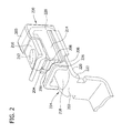
- FIG. 2 is a perspective view of an exemplary line strap insulator of the circuit breaker shown in FIG. 1
- FIG. 3 is a cross section of the line strap insulator shown in FIG. 2 .
- FIG. 4 is a top view of the line strap insulator shown in FIG. 2 .
- FIG. 5 is a front view of the line strap insulator shown in FIG. 2 installed in a circuit breaker.
- FIG. 6 is a block diagram of an exemplary method of assembling the circuit breaker shown in FIG. 1 .
- FIG. 1 shows a perspective view of an embodiment of a circuit breaker 100 .
- Circuit breaker 100 has a housing 102 that encloses an inner volume of circuit breaker 100 .
- the housing includes a base portion 106 and a cover portion 108 .
- a switch 104 extends through outside cover 108 and is accessible from outside housing 102 .
- Switch 104 is used to switch circuit breaker 100 from an off position to an on position, or vice versa.
- Switch 104 is also used to reset circuit breaker 100 after circuit breaker 100 has tripped.
- FIG. 1 illustrates a three pole circuit breaker 100 , however in other embodiments, circuit breaker 100 includes one or more poles.
- FIG. 2 shows an embodiment of a line strap insulator 200 .
- Line strap insulator 200 is sized and configured to fit within housing 102 of circuit breaker 100 ( FIG. 1 ).
- line strap insulator 200 is fabricated from a molded plastic material that is electrically insulative.
- Line strap insulator 200 is made from a casting or molding process, for example injection molding.
- line strap insulator 200 may be made from any material and process that enables circuit breaker 100 to function as described herein.
- line strap insulator 200 is electrically insulative up to 2,500 Volts, and is sufficient for a circuit breaker rating of 480 Volts and in another embodiment, line strap insulator 200 is electrically insulative up to 3,000 Volts and is sufficient for a circuit breaker rating of 600 Volts.
- circuit breaker rating refers to certification by Underwriter's Laboratory (UL) as a minimum voltage level before voltage creep occurs.
- Line strap insulator 200 is configured to insulate line strap 202 from other electrical components (not shown) of circuit breaker 100 .
- Line strap 202 is fabricated from a conductive material, such as copper, silver, nickel, gold, aluminum, other metals or metal alloys and combinations thereof.
- Line strap 202 is used as the electrical input terminal for circuit breaker 100 , sometimes referred to as the “hot” terminal, of circuit breaker 100 .
- a shunt block 204 is positioned within line strap insulator 200 .
- line strap insulator 200 wraps from a lower side 206 of shunt block 204 to an upper side 208 of shunt block 204 .
- line strap 202 includes a contact member mounting surface 210 located on upper side 208 of shunt block 204 .
- a contact member 212 is coupled to contact member mounting surface 210 , for example, by welding.
- Shunt blocks are also commonly referred to as a flux block, magnetic flux block or a flux shunt block.
- shunt block 204 is fabricated from a material that concentrates magnetic flux during a short circuit condition. The concentration of magnetic flux increases the repulsive force between line strap 202 and a contact arm (not shown) of circuit breaker 100 , thereby increasing the speed at which line strap 202 is disconnected from the contact arm during a short circuit condition.
- Line strap insulator 200 has a first wall 214 and an opposing second wall 216 .
- Line strap 202 has a top face 218 , a bottom face 220 , a first sidewall 222 and an opposing second sidewall 224 .
- Line strap 202 is insertable into line strap insulator 200 , such that at least first sidewall 222 and second sidewall 224 are substantially covered by first wall 214 and second wall 216 .
- line strap insulator 200 has a vertical portion 228 , formed by two substantially ninety degree bends, such line strap 202 has a substantially u-shaped longitudinal cross section.
- first wall 214 and second wall 216 extend from a point above the top face 218 of line strap 202 to a point below the bottom face of said line strap to insulate line strap 202 .
- “above” and below” refer to vertical directions when line strap insulator 200 is in an upright orientation, for example, as shown in FIG. 2 .
- rear section 230 of line strap insulator 200 extends rearward beyond vertical portion 228 of line strap 202 to insulate line strap 202 .
- line strap 202 is insulated by line strap insulator 200 without the use of dielectric paste.
- first sidewall 222 is in direct contact with first wall 214 and the second sidewall 224 is in direct contact with second wall 216 .
- FIG. 3 shows a side view of line strap insulator 200 in an upright orientation.
- line strap insulator 200 is sized such that a lowermost edge 300 of line strap insulator 200 extends below a lowermost edge 302 of line strap 202 .
- shunt block 204 includes a hole 304 , which may be threaded.
- Line strap 202 includes a complimentary hole 306 configured to align with hole 304 when shunt block 204 and line strap 202 are positioned in line strap insulator 200 .
- a fastener 308 is inserted into holes 304 and 306 to couple line strap 202 to shunt block 204 .
- Fastener 308 may be a screw, bolt, pin, or other fastener capable of coupling line strap 202 to shunt block 204 .
- FIG. 4 shows a top view of an embodiment of line strap insulator 200 .
- first wall 214 and second wall 216 have one or more projections 400 extending inwardly therefrom and facing shunt block 204 .
- “inward” refers to a direction toward a central axis C of line strap insulator 200 .
- Projections 400 are configured to align shunt block 204 and line strap insulator 200 such that hole 304 and hole 306 (shown in FIG. 3 ) are aligned with one another. Projections 400 thus allow a user to couple line strap 202 to shunt block 204 using fastener 308 , without misalignment.
- projections 400 are configured for snap-fit engagement with a front face 226 ( FIG. 2 ) of shunt block 204 .
- the term “snap-fit” refers to a frictional engagement amongst two or more components, wherein at least one component flexes when the components are being joined, and snaps into place once the components are engaged.
- shunt block 204 is configured to have recesses corresponding to projections 400 . Projections 400 are configured to substantially prevent translational movement of shunt block 204 along longitudinal centerline C.
- FIG. 5 shows a cross section of circuit breaker 100 having line strap insulator 200 installed therein.
- line strap insulator 200 is contained entirely within housing 102 of circuit breaker 100 . At least a lower portion 500 of base 106 of housing 102 is in direct contact with line strap insulator 200 .
- rear section 230 (shown in FIG. 2 ) of line strap insulator 200 extends rearward and is in direct contact with lower portion 500 .
- housing 102 includes a retention member that cooperates with at least one of first wall 214 and second wall 216 of line strap insulator 200 for retaining line strap insulator 200 in housing 102 .
- the retention member includes grooves 502 formed in base 500 .
- Grooves 502 are substantially parallel and extend longitudinally within lower portion 500 of housing 102 . Grooves 502 are sized and configured for seating engagement with a lower edges 504 and 506 of first wall 214 and second wall 216 , respectively. In one embodiment, when lower edges 504 and 506 are seated with (i.e., in an overlapping engagement with) grooves 502 of first wall 214 and second wall 216 , line strap insulator 200 is held by a friction fit within base 500 . The overlapping engagement of lower edges 504 and 506 with grooves 502 increases the insulation between line strap insulator 200 and other electrical components of circuit breaker 100 . In another embodiment, additional grooves are formed in lower portion 500 for engagement with rear section 230 for additional insulation of line strap 202 . In yet another embodiment, retention member of housing 102 includes one or more ridges, and at least one of first wall 214 and second wall 216 include a groove that cooperates with at least one of the ridges to retain line strap insulator 200 in housing 102
- lower portion 500 includes a hole 508 configured to align with hole 304 and hole 306 when line strap insulator 200 , line strap 202 and shunt block 204 are placed within housing 102 .
- line strap insulator 200 is held by a friction fit within base 500 in an orientation such that hole 508 , hole 304 and hole 306 are aligned.
- fastener 308 shown in FIG. 3 ).
- FIG. 6 is a block diagram of an exemplary method of assembling circuit breaker 100 .
- a circuit breaker housing 102 is provided 600 .
- a line strap 202 is positioned 602 within the line strap insulator 200 .
- shunt block 204 is then positioned within line strap insulator 200 and subsequently, the line strap insulator having the line strap 202 and shunt block 204 positioned therein is positioned within the lower portion 500 of housing 102 .
- line strap 202 is positioned at least partially within line strap insulator 200 and is in contact with first sidewall 222 and said second sidewall 224 such that each of the first sidewall and the second sidewall extend from a point above a top surface of the line strap to a point below a bottom surface of the line strap.
- the method includes inserting 606 fastener 308 through hole 508 , hole 306 and hole 304 to couple the base 500 to the line strap 202 and shunt block 204 .
- first sidewall and the second sidewall comprise opposing projections, and the method further includes positioning 604 a shunt block 204 (shown in FIG. 2 ) within the line strap insulator 200 (shown in FIG.
- positioning shunt block 204 includes snap-fitting shunt block 204 with projections 400 .
- a user may first put line strap 202 (shown in FIG. 2 ) into line strap insulator 200 outside of housing 102 (shown in FIG. 1 ). Then shunt block 204 is slid along line strap surface 218 (shown in FIG. 2 ) until it snaps into place within line strap insulator 200 .
- housing 102 As an assembly, it is now put into place within housing 102 , for example by placing the assembly into grooves 502 as described above. Once the assembly is pressed and aligned in base 102 , fastener 308 is inserted from outside of housing 102 through hole 508 , hole 306 and hole 304 to secure the assembly to housing 102 . In other embodiments, positioning of line strap 200 , shunt block 204 and line strap insulator 200 within housing 102 is performed in any order that allows the circuit breaker to function as described herein.
Landscapes
- Physics & Mathematics (AREA)
- Electromagnetism (AREA)
- Breakers (AREA)
Abstract
Description
Claims (20)
Priority Applications (4)
| Application Number | Priority Date | Filing Date | Title |
|---|---|---|---|
| US13/472,886 US9401251B2 (en) | 2012-05-16 | 2012-05-16 | Molded case circuit breaker |
| DE102013104914.1A DE102013104914B4 (en) | 2012-05-16 | 2013-05-13 | Circuit breaker with molded case |
| FR1354354A FR2990793A1 (en) | 2012-05-16 | 2013-05-15 | CIRCUIT BREAKER WITH MOLDED HOUSING |
| CN201310180895.7A CN103426694B (en) | 2012-05-16 | 2013-05-16 | Molded case circuit breaker |
Applications Claiming Priority (1)
| Application Number | Priority Date | Filing Date | Title |
|---|---|---|---|
| US13/472,886 US9401251B2 (en) | 2012-05-16 | 2012-05-16 | Molded case circuit breaker |
Publications (2)
| Publication Number | Publication Date |
|---|---|
| US20130306454A1 US20130306454A1 (en) | 2013-11-21 |
| US9401251B2 true US9401251B2 (en) | 2016-07-26 |
Family
ID=49511079
Family Applications (1)
| Application Number | Title | Priority Date | Filing Date |
|---|---|---|---|
| US13/472,886 Active 2033-05-29 US9401251B2 (en) | 2012-05-16 | 2012-05-16 | Molded case circuit breaker |
Country Status (3)
| Country | Link |
|---|---|
| US (1) | US9401251B2 (en) |
| DE (1) | DE102013104914B4 (en) |
| FR (1) | FR2990793A1 (en) |
Families Citing this family (2)
| Publication number | Priority date | Publication date | Assignee | Title |
|---|---|---|---|---|
| US9324528B1 (en) | 2014-11-17 | 2016-04-26 | General Electric Company | Magnetic trip mechanism for circuit breaker |
| USD842257S1 (en) | 2017-09-14 | 2019-03-05 | Eaton Intelligent Power Limited | Three phase bus mounted surge protection device |
Citations (22)
| Publication number | Priority date | Publication date | Assignee | Title |
|---|---|---|---|---|
| US3519978A (en) * | 1967-09-15 | 1970-07-07 | Essex International Inc | Connector construction |
| EP0206249A2 (en) | 1985-05-10 | 1986-12-30 | Mitsubishi Denki Kabushiki Kaisha | Circuit breaker |
| CN86105856A (en) | 1985-07-19 | 1987-02-18 | 西屋电气公司 | Molded case circuit breaker |
| US4654490A (en) | 1986-03-03 | 1987-03-31 | Westinghouse Electric Corp. | Reverse loop circuit breaker with high impedance stationary conductor |
| US4761626A (en) | 1984-12-26 | 1988-08-02 | Hitachi, Ltd. | Circuit breaker |
| US4970481A (en) | 1989-11-13 | 1990-11-13 | General Electric Company | Current limiting circuit breaker contact arm configuration |
| US5548258A (en) | 1994-04-26 | 1996-08-20 | Fuji Electric Co., Ltd. | Circuit breaker with insulation device |
| WO1999049489A1 (en) | 1998-03-25 | 1999-09-30 | Square D Company | Phase barrier for use in a multiphase circuit breaker |
| US6229413B1 (en) | 1999-10-19 | 2001-05-08 | General Electric Company | Support of stationary conductors for a circuit breaker |
| US6373014B1 (en) | 1998-12-28 | 2002-04-16 | Mitsubishi Denki Kabushiki Kaisha | Current limiting device and circuit interrupter having a current limiting function |
| US6480082B1 (en) | 1996-12-25 | 2002-11-12 | Hitachi, Ltd. | Circuit breaker |
| US6930577B2 (en) * | 2003-09-15 | 2005-08-16 | General Electric Company | Circuit breaker lug cover and gasket |
| US6942527B1 (en) * | 2004-02-19 | 2005-09-13 | Eaton Corporation | Dual function terminal assembly and electric power apparatus incorporating the same |
| KR20100047057A (en) | 2008-10-28 | 2010-05-07 | 현대중공업 주식회사 | Insulation of extinguishing grid of molded case circuit breaker |
| US7786831B2 (en) * | 2007-04-03 | 2010-08-31 | Ls Industrial Systems Co., Ltd. | Modular terminal for molded case circuit breaker and molded case circuit breaker having the same |
| KR101014205B1 (en) | 2010-08-02 | 2011-02-14 | 주식회사 비츠로테크 | Cradle of vacuum circuit breaker |
| CN201754387U (en) | 2009-11-25 | 2011-03-02 | 河南省电力公司南阳供电公司 | On-line insulation monitoring device for oil-poor circuit breaker |
| EP2315228A1 (en) | 2009-10-20 | 2011-04-27 | LS Industrial Systems Co., Ltd | Molded case circuit breaker having an instantaneous trip mechanism |
| JP2011138778A (en) | 2009-12-31 | 2011-07-14 | Ls Industrial Systems Co Ltd | Vacuum circuit breaker |
| US20110290624A1 (en) | 2010-05-28 | 2011-12-01 | ABB Techology AG | Switching chamber insulation arrangement for a circuit breaker |
| CN103077855A (en) | 2013-01-01 | 2013-05-01 | 苏州君丰辰电子科技有限公司 | Intelligent plastic shell switch |
| US8853576B2 (en) * | 2011-12-12 | 2014-10-07 | Eaton Corporation | Circuit breaker, circuit breaker terminal lug cover, and method of protecting a terminal lug |
Family Cites Families (1)
| Publication number | Priority date | Publication date | Assignee | Title |
|---|---|---|---|---|
| JP2573106Y2 (en) | 1991-10-14 | 1998-05-28 | 三菱電機株式会社 | Coil support device |
-
2012
- 2012-05-16 US US13/472,886 patent/US9401251B2/en active Active
-
2013
- 2013-05-13 DE DE102013104914.1A patent/DE102013104914B4/en active Active
- 2013-05-15 FR FR1354354A patent/FR2990793A1/en active Pending
Patent Citations (23)
| Publication number | Priority date | Publication date | Assignee | Title |
|---|---|---|---|---|
| US3519978A (en) * | 1967-09-15 | 1970-07-07 | Essex International Inc | Connector construction |
| US4761626A (en) | 1984-12-26 | 1988-08-02 | Hitachi, Ltd. | Circuit breaker |
| EP0206249A2 (en) | 1985-05-10 | 1986-12-30 | Mitsubishi Denki Kabushiki Kaisha | Circuit breaker |
| CN86105856A (en) | 1985-07-19 | 1987-02-18 | 西屋电气公司 | Molded case circuit breaker |
| US4654490A (en) | 1986-03-03 | 1987-03-31 | Westinghouse Electric Corp. | Reverse loop circuit breaker with high impedance stationary conductor |
| US4970481A (en) | 1989-11-13 | 1990-11-13 | General Electric Company | Current limiting circuit breaker contact arm configuration |
| US5548258A (en) | 1994-04-26 | 1996-08-20 | Fuji Electric Co., Ltd. | Circuit breaker with insulation device |
| US6480082B1 (en) | 1996-12-25 | 2002-11-12 | Hitachi, Ltd. | Circuit breaker |
| WO1999049489A1 (en) | 1998-03-25 | 1999-09-30 | Square D Company | Phase barrier for use in a multiphase circuit breaker |
| US6373014B1 (en) | 1998-12-28 | 2002-04-16 | Mitsubishi Denki Kabushiki Kaisha | Current limiting device and circuit interrupter having a current limiting function |
| US6229413B1 (en) | 1999-10-19 | 2001-05-08 | General Electric Company | Support of stationary conductors for a circuit breaker |
| US6930577B2 (en) * | 2003-09-15 | 2005-08-16 | General Electric Company | Circuit breaker lug cover and gasket |
| US6942527B1 (en) * | 2004-02-19 | 2005-09-13 | Eaton Corporation | Dual function terminal assembly and electric power apparatus incorporating the same |
| US7786831B2 (en) * | 2007-04-03 | 2010-08-31 | Ls Industrial Systems Co., Ltd. | Modular terminal for molded case circuit breaker and molded case circuit breaker having the same |
| KR20100047057A (en) | 2008-10-28 | 2010-05-07 | 현대중공업 주식회사 | Insulation of extinguishing grid of molded case circuit breaker |
| EP2315228A1 (en) | 2009-10-20 | 2011-04-27 | LS Industrial Systems Co., Ltd | Molded case circuit breaker having an instantaneous trip mechanism |
| JP2011091042A (en) | 2009-10-20 | 2011-05-06 | Ls Industrial Systems Co Ltd | Circuit breaker for wiring with instantaneous tripping mechanism |
| CN201754387U (en) | 2009-11-25 | 2011-03-02 | 河南省电力公司南阳供电公司 | On-line insulation monitoring device for oil-poor circuit breaker |
| JP2011138778A (en) | 2009-12-31 | 2011-07-14 | Ls Industrial Systems Co Ltd | Vacuum circuit breaker |
| US20110290624A1 (en) | 2010-05-28 | 2011-12-01 | ABB Techology AG | Switching chamber insulation arrangement for a circuit breaker |
| KR101014205B1 (en) | 2010-08-02 | 2011-02-14 | 주식회사 비츠로테크 | Cradle of vacuum circuit breaker |
| US8853576B2 (en) * | 2011-12-12 | 2014-10-07 | Eaton Corporation | Circuit breaker, circuit breaker terminal lug cover, and method of protecting a terminal lug |
| CN103077855A (en) | 2013-01-01 | 2013-05-01 | 苏州君丰辰电子科技有限公司 | Intelligent plastic shell switch |
Non-Patent Citations (4)
| Title |
|---|
| Bosma, A. et al.; High-Voltage Live Tank Circuit-Breakers with Composite Insulators; IEEE 2000; pp. 1217-1222; vol. 3. |
| First Office Action issued in connection with Chinese Application No. 201310180895.7, dated Jan. 29, 2016, 6 pages. |
| Unofficial English Translation of First Office Action issued in connection with Chinese Application No. 201310180895.7, dated Jan. 29, 2016, 7 pages. |
| Unofficial translation of French Search Report and Written Opinion from corresponding FR Application No. 1354354 dated May 16, 2014. |
Also Published As
| Publication number | Publication date |
|---|---|
| FR2990793A1 (en) | 2013-11-22 |
| DE102013104914A1 (en) | 2013-11-21 |
| CN103426694A (en) | 2013-12-04 |
| US20130306454A1 (en) | 2013-11-21 |
| DE102013104914B4 (en) | 2023-06-15 |
Similar Documents
| Publication | Publication Date | Title |
|---|---|---|
| US9450347B2 (en) | Power cord | |
| US9589745B2 (en) | Power cord having thermal sensor | |
| US8493170B2 (en) | Overvoltage protection device having one or more parallel-connected overvoltage-limiting elements located in one physical unit | |
| EP2929554B1 (en) | Circuit breaker terminal shield with position indicator | |
| US9653854B2 (en) | Power cord | |
| CN106068584B (en) | Disconnection device splicing block and modularization surge device | |
| US10283293B2 (en) | Thermal circuit breaker | |
| US8169283B2 (en) | Circuit breaker trip unit support | |
| US20120019345A1 (en) | Compact modular fuse block with integrated fuse clearance | |
| US9401251B2 (en) | Molded case circuit breaker | |
| RU2719326C2 (en) | Electric protective device in modular format | |
| KR200483632Y1 (en) | Plug switch | |
| US10763067B1 (en) | Panel wire install indicator of a residential circuit breaker | |
| CN103426694B (en) | Molded case circuit breaker | |
| CN102610456A (en) | Thermomagnetic circuit breaker and power distribution equipment | |
| CA2927698A1 (en) | Connector assemblies for panel board neutral bars and circuit breakers including same | |
| US20150145636A1 (en) | Circuit breaker heater-bimetal assembly, heater-bimetal apparatus, and assembly methods thereof | |
| KR101651749B1 (en) | Circuit breaker | |
| JP2008017674A (en) | Test plug | |
| CN209981105U (en) | Three-phase protector and electrical equipment | |
| AU2012314168A1 (en) | Anti-gaping device designed for a zone joining two portions of adjacent shells of a housing of a modular electrical apparatus | |
| JP2000173438A (en) | Earth leakage breaker | |
| KR101045413B1 (en) | Circuit Breaker | |
| KR20200061998A (en) | Protection element |
Legal Events
| Date | Code | Title | Description |
|---|---|---|---|
| AS | Assignment |
Owner name: GENERAL ELECTRIC COMPANY, NEW YORK Free format text: ASSIGNMENT OF ASSIGNORS INTEREST;ASSIGNORS:NICKERSON, DOUGLAS ALVAN;DONCET, JONATHAN RICH;REEL/FRAME:028218/0474 Effective date: 20120515 |
|
| FEPP | Fee payment procedure |
Free format text: PAYOR NUMBER ASSIGNED (ORIGINAL EVENT CODE: ASPN); ENTITY STATUS OF PATENT OWNER: LARGE ENTITY |
|
| STCF | Information on status: patent grant |
Free format text: PATENTED CASE |
|
| MAFP | Maintenance fee payment |
Free format text: PAYMENT OF MAINTENANCE FEE, 4TH YEAR, LARGE ENTITY (ORIGINAL EVENT CODE: M1551); ENTITY STATUS OF PATENT OWNER: LARGE ENTITY Year of fee payment: 4 |
|
| AS | Assignment |
Owner name: ABB SCHWEIZ AG, SWITZERLAND Free format text: ASSIGNMENT OF ASSIGNORS INTEREST;ASSIGNOR:GENERAL ELECTRIC COMPANY;REEL/FRAME:052431/0538 Effective date: 20180720 |
|
| AS | Assignment |
Owner name: ABB S.P.A., ITALY Free format text: ASSIGNMENT OF ASSIGNORS INTEREST;ASSIGNOR:ABB SCHWEIZ AG;REEL/FRAME:058878/0740 Effective date: 20211108 |
|
| MAFP | Maintenance fee payment |
Free format text: PAYMENT OF MAINTENANCE FEE, 8TH YEAR, LARGE ENTITY (ORIGINAL EVENT CODE: M1552); ENTITY STATUS OF PATENT OWNER: LARGE ENTITY Year of fee payment: 8 |