EP2791920B1 - Dokumentführungssysteme und verfahren mit einem dokumentvorlageplatte - Google Patents
Dokumentführungssysteme und verfahren mit einem dokumentvorlageplatte Download PDFInfo
- Publication number
- EP2791920B1 EP2791920B1 EP12858113.9A EP12858113A EP2791920B1 EP 2791920 B1 EP2791920 B1 EP 2791920B1 EP 12858113 A EP12858113 A EP 12858113A EP 2791920 B1 EP2791920 B1 EP 2791920B1
- Authority
- EP
- European Patent Office
- Prior art keywords
- document
- platen
- document platen
- entry
- aperture
- Prior art date
- Legal status (The legal status is an assumption and is not a legal conclusion. Google has not performed a legal analysis and makes no representation as to the accuracy of the status listed.)
- Not-in-force
Links
- 238000000034 method Methods 0.000 title description 3
- 230000005670 electromagnetic radiation Effects 0.000 claims description 52
- 238000003384 imaging method Methods 0.000 claims description 40
- 239000000463 material Substances 0.000 description 17
- 238000005286 illumination Methods 0.000 description 12
- 239000011248 coating agent Substances 0.000 description 8
- 238000000576 coating method Methods 0.000 description 8
- 239000004033 plastic Substances 0.000 description 5
- 239000000126 substance Substances 0.000 description 5
- 229910052782 aluminium Inorganic materials 0.000 description 4
- XAGFODPZIPBFFR-UHFFFAOYSA-N aluminium Chemical compound [Al] XAGFODPZIPBFFR-UHFFFAOYSA-N 0.000 description 4
- -1 but not limited to Substances 0.000 description 3
- 230000008878 coupling Effects 0.000 description 3
- 238000010168 coupling process Methods 0.000 description 3
- 238000005859 coupling reaction Methods 0.000 description 3
- 229920002994 synthetic fiber Polymers 0.000 description 3
- 239000000853 adhesive Substances 0.000 description 2
- 230000001070 adhesive effect Effects 0.000 description 2
- 229910052751 metal Inorganic materials 0.000 description 2
- 239000002184 metal Substances 0.000 description 2
- 230000003287 optical effect Effects 0.000 description 2
- 239000003973 paint Substances 0.000 description 2
- 230000002411 adverse Effects 0.000 description 1
- 230000004075 alteration Effects 0.000 description 1
- 238000013459 approach Methods 0.000 description 1
- 238000005452 bending Methods 0.000 description 1
- 239000002131 composite material Substances 0.000 description 1
- 230000003247 decreasing effect Effects 0.000 description 1
- 239000003292 glue Substances 0.000 description 1
- 230000001788 irregular Effects 0.000 description 1
- 230000005855 radiation Effects 0.000 description 1
- 238000006467 substitution reaction Methods 0.000 description 1
- 239000013589 supplement Substances 0.000 description 1
- 230000007704 transition Effects 0.000 description 1
- 238000011144 upstream manufacturing Methods 0.000 description 1
- 238000003466 welding Methods 0.000 description 1
- 230000037303 wrinkles Effects 0.000 description 1
Images






Classifications
-
- G—PHYSICS
- G07—CHECKING-DEVICES
- G07D—HANDLING OF COINS OR VALUABLE PAPERS, e.g. TESTING, SORTING BY DENOMINATIONS, COUNTING, DISPENSING, CHANGING OR DEPOSITING
- G07D7/00—Testing specially adapted to determine the identity or genuineness of valuable papers or for segregating those which are unacceptable, e.g. banknotes that are alien to a currency
- G07D7/06—Testing specially adapted to determine the identity or genuineness of valuable papers or for segregating those which are unacceptable, e.g. banknotes that are alien to a currency using wave or particle radiation
- G07D7/12—Visible light, infrared or ultraviolet radiation
- G07D7/121—Apparatus characterised by sensor details
-
- B—PERFORMING OPERATIONS; TRANSPORTING
- B65—CONVEYING; PACKING; STORING; HANDLING THIN OR FILAMENTARY MATERIAL
- B65H—HANDLING THIN OR FILAMENTARY MATERIAL, e.g. SHEETS, WEBS, CABLES
- B65H9/00—Registering, e.g. orientating, articles; Devices therefor
- B65H9/04—Fixed or adjustable stops or gauges
-
- B—PERFORMING OPERATIONS; TRANSPORTING
- B65—CONVEYING; PACKING; STORING; HANDLING THIN OR FILAMENTARY MATERIAL
- B65H—HANDLING THIN OR FILAMENTARY MATERIAL, e.g. SHEETS, WEBS, CABLES
- B65H43/00—Use of control, checking, or safety devices, e.g. automatic devices comprising an element for sensing a variable
-
- B—PERFORMING OPERATIONS; TRANSPORTING
- B65—CONVEYING; PACKING; STORING; HANDLING THIN OR FILAMENTARY MATERIAL
- B65H—HANDLING THIN OR FILAMENTARY MATERIAL, e.g. SHEETS, WEBS, CABLES
- B65H5/00—Feeding articles separated from piles; Feeding articles to machines
- B65H5/02—Feeding articles separated from piles; Feeding articles to machines by belts or chains, e.g. between belts or chains
- B65H5/021—Feeding articles separated from piles; Feeding articles to machines by belts or chains, e.g. between belts or chains by belts
- B65H5/026—Feeding articles separated from piles; Feeding articles to machines by belts or chains, e.g. between belts or chains by belts between belts and stationary pressing, supporting or guiding elements forming a transport nip
-
- B—PERFORMING OPERATIONS; TRANSPORTING
- B65—CONVEYING; PACKING; STORING; HANDLING THIN OR FILAMENTARY MATERIAL
- B65H—HANDLING THIN OR FILAMENTARY MATERIAL, e.g. SHEETS, WEBS, CABLES
- B65H5/00—Feeding articles separated from piles; Feeding articles to machines
- B65H5/36—Article guides or smoothers, e.g. movable in operation
- B65H5/38—Article guides or smoothers, e.g. movable in operation immovable in operation
-
- B—PERFORMING OPERATIONS; TRANSPORTING
- B65—CONVEYING; PACKING; STORING; HANDLING THIN OR FILAMENTARY MATERIAL
- B65H—HANDLING THIN OR FILAMENTARY MATERIAL, e.g. SHEETS, WEBS, CABLES
- B65H7/00—Controlling article feeding, separating, pile-advancing, or associated apparatus, to take account of incorrect feeding, absence of articles, or presence of faulty articles
- B65H7/02—Controlling article feeding, separating, pile-advancing, or associated apparatus, to take account of incorrect feeding, absence of articles, or presence of faulty articles by feelers or detectors
- B65H7/14—Controlling article feeding, separating, pile-advancing, or associated apparatus, to take account of incorrect feeding, absence of articles, or presence of faulty articles by feelers or detectors by photoelectric feelers or detectors
-
- H—ELECTRICITY
- H04—ELECTRIC COMMUNICATION TECHNIQUE
- H04N—PICTORIAL COMMUNICATION, e.g. TELEVISION
- H04N1/00—Scanning, transmission or reproduction of documents or the like, e.g. facsimile transmission; Details thereof
- H04N1/04—Scanning arrangements, i.e. arrangements for the displacement of active reading or reproducing elements relative to the original or reproducing medium, or vice versa
- H04N1/12—Scanning arrangements, i.e. arrangements for the displacement of active reading or reproducing elements relative to the original or reproducing medium, or vice versa using the sheet-feed movement or the medium-advance or the drum-rotation movement as the slow scanning component, e.g. arrangements for the main-scanning
- H04N1/121—Feeding arrangements
- H04N1/1215—Feeding using one or more cylindrical platens or rollers in the immediate vicinity of the main scanning line
-
- H—ELECTRICITY
- H04—ELECTRIC COMMUNICATION TECHNIQUE
- H04N—PICTORIAL COMMUNICATION, e.g. TELEVISION
- H04N1/00—Scanning, transmission or reproduction of documents or the like, e.g. facsimile transmission; Details thereof
- H04N1/04—Scanning arrangements, i.e. arrangements for the displacement of active reading or reproducing elements relative to the original or reproducing medium, or vice versa
- H04N1/12—Scanning arrangements, i.e. arrangements for the displacement of active reading or reproducing elements relative to the original or reproducing medium, or vice versa using the sheet-feed movement or the medium-advance or the drum-rotation movement as the slow scanning component, e.g. arrangements for the main-scanning
- H04N1/121—Feeding arrangements
- H04N1/122—Feeding arrangements using a feed belt
-
- H—ELECTRICITY
- H04—ELECTRIC COMMUNICATION TECHNIQUE
- H04N—PICTORIAL COMMUNICATION, e.g. TELEVISION
- H04N1/00—Scanning, transmission or reproduction of documents or the like, e.g. facsimile transmission; Details thereof
- H04N1/04—Scanning arrangements, i.e. arrangements for the displacement of active reading or reproducing elements relative to the original or reproducing medium, or vice versa
- H04N1/12—Scanning arrangements, i.e. arrangements for the displacement of active reading or reproducing elements relative to the original or reproducing medium, or vice versa using the sheet-feed movement or the medium-advance or the drum-rotation movement as the slow scanning component, e.g. arrangements for the main-scanning
- H04N1/121—Feeding arrangements
- H04N1/123—Using a dedicated sheet guide element
-
- B—PERFORMING OPERATIONS; TRANSPORTING
- B65—CONVEYING; PACKING; STORING; HANDLING THIN OR FILAMENTARY MATERIAL
- B65H—HANDLING THIN OR FILAMENTARY MATERIAL, e.g. SHEETS, WEBS, CABLES
- B65H2404/00—Parts for transporting or guiding the handled material
- B65H2404/20—Belts
- B65H2404/26—Particular arrangement of belt, or belts
- B65H2404/268—Arrangement of belts facing a transport surface, e.g. contact glass in copy machine
-
- B—PERFORMING OPERATIONS; TRANSPORTING
- B65—CONVEYING; PACKING; STORING; HANDLING THIN OR FILAMENTARY MATERIAL
- B65H—HANDLING THIN OR FILAMENTARY MATERIAL, e.g. SHEETS, WEBS, CABLES
- B65H2404/00—Parts for transporting or guiding the handled material
- B65H2404/60—Other elements in face contact with handled material
- B65H2404/61—Longitudinally-extending strips, tubes, plates, or wires
- B65H2404/611—Longitudinally-extending strips, tubes, plates, or wires arranged to form a channel
-
- B—PERFORMING OPERATIONS; TRANSPORTING
- B65—CONVEYING; PACKING; STORING; HANDLING THIN OR FILAMENTARY MATERIAL
- B65H—HANDLING THIN OR FILAMENTARY MATERIAL, e.g. SHEETS, WEBS, CABLES
- B65H2553/00—Sensing or detecting means
- B65H2553/40—Sensing or detecting means using optical, e.g. photographic, elements
- B65H2553/41—Photoelectric detectors
- B65H2553/412—Photoelectric detectors in barrier arrangements, i.e. emitter facing a receptor element
-
- B—PERFORMING OPERATIONS; TRANSPORTING
- B65—CONVEYING; PACKING; STORING; HANDLING THIN OR FILAMENTARY MATERIAL
- B65H—HANDLING THIN OR FILAMENTARY MATERIAL, e.g. SHEETS, WEBS, CABLES
- B65H2553/00—Sensing or detecting means
- B65H2553/40—Sensing or detecting means using optical, e.g. photographic, elements
- B65H2553/41—Photoelectric detectors
- B65H2553/414—Photoelectric detectors involving receptor receiving light reflected by a reflecting surface and emitted by a separate emitter
-
- B—PERFORMING OPERATIONS; TRANSPORTING
- B65—CONVEYING; PACKING; STORING; HANDLING THIN OR FILAMENTARY MATERIAL
- B65H—HANDLING THIN OR FILAMENTARY MATERIAL, e.g. SHEETS, WEBS, CABLES
- B65H2701/00—Handled material; Storage means
- B65H2701/10—Handled articles or webs
- B65H2701/19—Specific article or web
- B65H2701/1912—Banknotes, bills and cheques or the like
Definitions
- the illustrative embodiments relate generally to document guide systems, and more particularly, to document guide systems and methods employing a document platen.
- Documents such as banknotes (e.g., paper money, plastic money, etc.), checks, legal-related documents, or any other type of document, may need to be processed or analyzed for a wide variety of purposes.
- Guide systems may be employed to guide or position a document while it is being processed or analyzed. Such guide systems may be used in conjunction with machines that move documents through a series of processing steps using, e.g., belts, rings, rollers, or other means of moving a document,
- currently available document guide systems may fail to properly position or flatten a document, thus decreasing the effectiveness of its processing or analysis capabilities.
- current document guide systems may fail to properly flatten or straighten a document against a surface to minimize folds, wrinkles, or waviness that may adversely affect document processing or analysis.
- shape or size of some current document guide systems may be inappropriate for placement in certain locations within a document processing machine, thus limiting the ability of those current systems from being employed in current document processing machines. Indeed, these and other issues have limited the effectiveness of some current document guide systems.
- EP0311821 A2 describes a device for transporting documents having a position for optically reading the document, a first pair of a transport roller and a pinch roller therefor disposed in the transport path upstream from the reading position, and a second pair of a transport roller and pinch roller therefor disposed in the transport path downstream from the reading position, the transport path being defined by an upper guide plate and a lower guide plate, the transport path having two document contact portions provided respectively between the reading position and the first pair of rollers and between the reading position and the second pair of rollers to come into sliding contact with the document during transport, the two document contact portions; being formed by bending at least one of the upper and lower guide plates. Furthermore, the document discloses a guide system according to the preamble of claim 1.
- WO2008/061241 A2 provides a method and apparatus maintaining surface smoothness of note as they pass through a high speed processing machine.
- a note fed into the processing machine is carried through the machine by a series of conveyor belts.
- the note is conveyed past a line scan camera that records the note as it crosses a gap while passing from a first conveyor belt to a second conveyor belt that is approximately orthogonal to the first conveyor belt.
- a curved note guide directs the path of the note, helping it make the 90 degree turn as it crosses the gap between the conveyor belts.
- the inertia of the note causes it to remain flush against the surface of the curved guide, allowing the line scan camera to record each line of the surface of the note with equal resolution.
- US2003/030854 A1 describes a focusing apparatus of an automatic document feeder, having the automatic document feeder has a scanning zone for an optical chassis to retrieve an image of a document.
- the focusing apparatus of automatic document feeder comprises at least one focusing chart, which is disposed at a location corresponding to the scanning zone.
- the focusing chart is comprised of a plurality of focus detecting elements and capable of automatic focusing by the optical chassis.
- a document guide system employing a document platen includes a document platen having a first, document-faceable side and a second, opposing side, and a document support sub-system adjacent the first side of the document platen.
- the document support sub-system and the first side of the document platen are adapted to receive a document therebetween, and the document platen forms an aperture adapted to allow electromagnetic radiation therethrough, characterised in that the second side of the document platen forms an indent having angled sides, the aperture located at approximately an apex of the indent.
- the document platen of the document guide system has an entry portion and an exit portion.
- the document platen further includes a first roller at least partially within the entry portion of the document platen, and a second roller at least partially within the exit portion of the document platen.
- the document guide system includes a document support sub-system adjacent the first side of the document platen. The document support sub-system and the first side of the document platen are adapted to receive a document therebetween.
- the document has a direction of travel from the entry portion to the exit portion of the document platen.
- the document platen forms an aperture adapted to allow electromagnetic radiation therethrough, and the first roller and the second roller are rotatable to facilitate movement of the document in the document direction of travel.
- the document platen of the document guide system has an entry edge and an exit edge.
- the document guide system includes a document support sub-system adjacent the first side of the document platen.
- the document support sub-system and the first side of the document platen are positioned to allow a document to pass between the document support sub-system and the first side of the document platen.
- the document platen forms an aperture located at approximately a midpoint between the entry edge and the exit edge.
- the document guide system includes one or more electromagnetic radiation sources aimed at the aperture of the document platen to illuminate at least a portion of the document at the aperture of the document platen, and an imaging device aimed at the aperture of the document platen to capture an image of at least a portion of the document at the aperture of the document platen.
- the imaging device is positioned on an opposite side of the document platen than the document support sub-system.
- the imaging device has a line of sight substantially perpendicular to the first side of the document platen.
- the document 102 may be any type of document on which processing or analysis may be performed, including, but not limited to, banknotes from any country of origin, financial documents (e.g., checks, money orders, travelers checks, etc.), legal related documents, etc. Unless otherwise indicated, as used herein, "or" does not require mutual exclusivity.
- the document 102 may also be formed from any material, including paper, plastic, synthetic materials, etc.
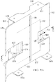
- the document 102 has a direction of travel 103 from an entry edge 104 to an exit edge 105 of the document platen 100. As the document 102 moves past an aperture 106 formed by the document platen 100, the document 102 may be analyzed or processed in any manner, including using the systems described herein.
- the document 102 may move across a first, document-faceable side 107 of the document platen 100.
- the document 102 may be held or moved across the first side 107 of the document platen 100 using a document support sub-system, which is not shown in Figures 1A-C , but is shown and described in more detail below.
- the document 102 may move between the first side 107 of the document platen 100 and the document support sub-system (not shown) as the document 102 moves in its direction of travel 103.
- the first side 107 of the document platen 100 may be a substantially flat surface against which the document 102 may be held or moved.
- the first side 107 of the document platen 102 is not limited to flat surfaces only, as the first side 107 may form a curve or arc that is either concave or convex, depending on the embodiment.
- Other shapes of the first side 107 of the document platen 100 are also possible in the embodiments.
- the document platen 100 also has a second side 108 that opposes the first, document-faceable side 107.
- the second side 108 of the document platen 100 forms an indent 110.
- the aperture 106 is located at approximately the apex 111 of the indent 110.
- the indent 110 has angled sides 112, 113.
- the angled sides 112, 113 of the indent 110 may form angles 114, 115 with the first side 107 of the document platen 100, respectively.
- each of the first angle 114 and the second angle 115 may be in a range from 5° to 85° (e.g., 15°, 30°, 45°, 60°, 70°, etc.).
- first and second angles 114, 115 are shown as being substantially the same as one another in Figures 1A-C , the first angle 114 may differ from the second angle 115, in one embodiment. In yet another embodiment, either or both of the first and second angles 114, 115 may be 90°, or approximate thereto, in which case the indent 110 has straight, as opposed to angled, sides. As will be discussed in more detail below, the angled sides 112, 113 of the indent 110 may allow lines of sight from various components (e.g., camera, electromagnetic radiation sources, etc.) aimed at the aperture 106 from multiple or various angles or positions.
- various components e.g., camera, electromagnetic radiation sources, etc.
- the aperture 106 formed by the document platen 100 may be any space, hole, or gap that allows electromagnetic radiation therethrough, or allows a line of sight to a passing document 102.
- the aperture 106 may be located at approximately a midpoint between the entry edge 104 and the exit edge 105 of the document platen 100.
- the aperture 106 may be an elongated slit, as shown in Figures 1A-C .
- the elongated slit may be substantially perpendicular to the direction of travel 103 of the document 102.
- the aperture 106 is shown to be an elongated slit, the aperture 106 may have any shape (e.g., circle, oval, polygonal, irregular, adjustable, etc.), and may also be elongated along different directions (e.g., parallel with document direction of travel 103, diagonally, etc.) than that shown in Figures 1A-C .
- the elongated slit may have a top end 118 that is adjacent or near the top side 120 of the document platen 100 and a bottom end 119 that is adjacent or near the bottom side 121 of the document platen 100.
- the aperture 106 may allow a electromagnetic radiation source to transmit electromagnetic radiation to or through the document 102, and may also allow an imaging device (e.g., camera) to capture one or more images of the document 102 as it passes by the aperture 106.
- the length 116 of the aperture 106 may also meet or exceed the height 117 of the document 102; as a result, the entire height of the document 102 may be processed or analyzed using the aperture 106, according to one embodiment. In yet another embodiment, the length 116 of the aperture 106 may be less than the height 117 of the document 102.
- the document platen 100 may also include a first roller 122 and a second roller 123 that are rotatable to facilitate movement of the document 102 in its direction of travel 103.
- first roller 122 may be at, within, or at least partially within the first portion 124 of the document platen 100.
- the second roller 123 may be located at, within, or at least partially within the exit portion 125 of the document platen 100.
- the roller 122 may be located substantially within a cutout portion 126 of the entry portion 124 of the document platen 100, and the second roller 123 may be located substantially within a cutout portion 127 of the exit portion 125 of the document platen 100. While the first and second rollers 122, 123 are shown to be substantially located and rotatable within their respective portions 124, 125 of the document platen 100, the rollers 122, 123 are not limited to being embedded within the structure of the document platen 100 and may protrude therefrom more than is shown in Figures 1A-C . Also, the first and second rollers 122, 123 may be substantially cylindrical and rotate in the direction of travel 103 of the document 102. The rollers 122, 123 may be located anywhere that permits contact with the document 102 such that they may facilitate movement of the document 102 in the direction of travel 103.
- rollers 122, 123 may be freely rotatable, without the use of a motivating force, to facilitate movement of the document 102 in its direction of travel 103, the rollers 122, 123 may also be subjected to a motivating force that rotates the rollers 122, 123 such that they move the document 102 in its direction of travel 103. Rotation of the rollers 122, 123 may be accomplished using any motivating means, such as a motor, or, as shown below, one or more belts.
- the document platen 100 may have any number of rollers to facilitate movement of the document 102, and these rollers may be placed at various positions on the document platen 100.
- the document platen 100 may have one or more rollers located only on either the entry portion 124 or the exit portion 125 of the document platen 100.
- the document platen 100 may have no rollers at all.
- the entry portion 124 of the document platen 100 may also have a tapered entry edge 128 that guides the document 102 into a space between the first side 107 of the document platen 100 and the document support sub-system (not shown in Figures 1A-C , but shown below).
- the tapered entry edge 128 may help to ensure that the document 102 is properly positioned and moved along the first side 107 of the document platen 100, and help to prevent document jamming.
- the angle or degree of the taper of the tapered entry edge 128 may vary.
- the document platen 100 may be formed from any material, including, but not limited to, metal, plastic, synthetic material, rubber, etc.
- the document platen 100 may be formed from aluminum 6061-T6 or other equivalent material.
- any of the parts or elements described herein may be formed from the aforementioned materials, including aluminum 6061-T6 or other equivalent material.
- the document platen 100 may also have a finish or coating.
- the first side 107 of the document platen 100, the second side 108 of the document platen 100, the apex 111, angled sides 112, 113, or any other portion of the indent 110, the edges of the aperture 106, the side(s) of the document platen 100, or any other portion of the document platen 100 may be coated or covered with a finish or coating.
- the finish or coating include black anodized or any other non-reflective material (e.g., paint, adhesive material, or any other substance that will not reflect electromagnetic radiation or light).
- the coating or finish may be a reflective material.
- the document platen 100 may be anchored to a surface in any manner, including by the use of one or more anchor tabs 130, 131.
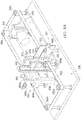
- an illustrative embodiment of a document guide system 236 includes the document platen 200, a document support sub-system 238, and a document 202 traveling therebetween in its direction of travel 203. Elements of Figure 2 that are analogous to elements in Figures 1A-C have been shown by indexing the reference numerals by 100.
- the document support sub-system 238 includes an upper band 240 and a lower band 241 that hold the document 202 against the first side 207 of the document platen 200 when the document 202 moves along the first side 207 of the document platen 200 and between the bands 240, 241 and the first side 207 of the document platen 200.
- the upper and lower bands 240, 241 are supported by a first post 242, located adjacent the entry edge 204 of the document platen 200, and a second post 243, located adjacent the exit edge 205 of the document platen 200.
- the first post 242 may have an upper portion 244 and a lower portion 245.
- the second post 243 may have an upper portion 246 and a lower portion 247.
- the upper and lower portions 244, 245, 246, 247 of the first and second posts 242, 243 may be enlarged, or have a greater diameter or circumference, as compared to other portions of the posts 242, 243.
- the upper and lower portions 244, 245, 246, 247 need not be enlarged as shown in Figure 2 .
- the upper band 240 is wrapped partially around the upper portion 244 of the first post 242 and partially around the upper portion 246 of the second post 243 so as to be elongated, or stretched, from the first post 242 to the second post 243.
- the lower band 241 is wrapped partially around the lower portion 245 of the first post 242 and partially around the lower portion 247 of the second post 243 so as to be elongated, or stretched, from the first post 242 to the second post 243,
- the upper and lower bands 240, 241 are also adjacent the first side 207 of the document platen 200 so as to at least partially press the document 202 against the first side 207 of the document platen 200 when the document 202 passes between the first side 207 of the document platen 200 and the bands 240, 241.
- the upper and lower bands 240, 241 are spaced from one another such that they make contact with upper and lower portions of the document 202.
- the upper and lower bands 240, 241 may be made from any material, such as plastic, rubber, synthetic materials, etc.
- each of the upper and lower bands 240, 241 are O-rings that are stretched so as to wrap around the first and second posts 242, 243 as shown in Figure 2 .
- the document guide system 236 may include any number of bands (e.g., 1, 2, 3, 5, 10, etc.).
- the first and second post 242, 243 may be rotatable to cause rotation of the upper and lower bands 240, 241, thus facilitating movement of the document 202 in its direction of travel 203.
- Either or both of the first and second posts 242, 243 may be motivated to rotate using, for example, a motor or belts, so that the upper and lower bands 240, 241 impart force or motion upon the document 202 in its direction of travel 203.
- belts 248, 249 may partially wrap around middle portions 250, 251 of the first and second posts 242, 243, respectively.
- first and second posts 242, 243 When the belts 248, 249 are put into motion, they may rotate the first and second posts 242, 243 in a clockwise direction (from the perspective shown in Figure 2 ), thereby imparting motion upon the upper and lower bands 240, 241, and ultimately the document 202 in its direction of travel 203,
- the middle portions 250, 251 of the first and second posts 242, 243, respectively, may also be enlarged in a similar fashion as the upper and lower portions 244, 245, 246, 247 of the first and second posts 242, 243.
- either or both of the first and second posts 242, 243 may be motivated to rotate in a more direct fashion using one or more motors (without the use of an intervening belt).
- first and second posts 242, 243 may not be motivated to rotate at all, and may either freely rotate or be stationary; in this embodiment, the upper and lower bands 240, 241 may still serve the function of holding the document 202 against first side 207 of the document platen 200.
- an illustrative embodiment of the document guide system 336 includes the document platen 300, the document support sub-system 338, and the document 302 passing between the document support sub-system 338 and the first side 307 of the document platen 300 in the direction of travel 303.
- Elements of Figures 3 , 4A , and 4B that are analogous to elements in Figures 1A-C or 2 have been shown by indexing the reference numerals by a multiple of 100.
- the document guide system 336 may be used to capture one or more images of the document 302 using illumination that is transmitted through the document 302.
- the document guide system 336 includes an imaging device 354 that is positioned on an opposite side of the document platen 300 as the document support sub-system 338.
- the imaging device 354 is aimed at the aperture 306 of the document platen 300, and has a line of sight 355 that is substantially perpendicular to the first side 307 of the document platen 300, as indicated by angle 356.
- the imaging device 354 may capture an image of at least a portion of the document 302 at the aperture 306 of the document platen 300 as the document 302 moves in its direction of travel 303.
- the imaging device 354 may be a frame camera or line scan camera in some of the illustrative embodiments.
- any suitable imaging device capable of capturing any suitable image (frame, line, or otherwise) of the document 302, or portion thereof, may be employed and remain within the scope of the present disclosure.
- the imaging device 354 may be a TDI camera, a frame camera, an x-ray imaging device, an infrared camera, etc.
- the document guide system 336 also may include an electromagnetic radiation source 358 aimed at the aperture 306 of the document platen 300 so as to form an angle 359 that is approximately 90°.
- the electromagnetic radiation source 358 may have a line of sight 360 that forms the angle 359 with the first side 307 of the document platen 300 that is approximately 90°.
- the electromagnetic radiation source 358 may emit any type of electromagnetic radiation (e.g., ultraviolet, infrared, white, green, blue, x-ray, visible, etc.) or other suitable electromagnetic radiation, including light.
- the imaging device 354 is on an opposite side of the document platen 300 as the electromagnetic radiation source 358.
- the imaging device 354 may capture one or more images of at least a portion of the document 302 at or near the aperture 306 that is illuminated by transmissive electromagnetic radiation or light from the electromagnetic radiation source 358.
- electromagnetic radiation from the electromagnetic radiation source 358 may illuminate and pass through the portion of the document 302 that is in front of the aperture 306, thereby allowing the imaging device 354 to capture an image of that portion of the document 302 using the electromagnetic radiation transmitted through the document 302.
- the document 302 is moved in its direction of travel 303 along the first side 307 of the document platen 300 as the imaging device 354 captures one or more images of the document 302 using electromagnetic radiation transmitted from the electromagnetic radiation source 358 and through the document 302.
- belts 362 and 363 are used in conjunction with multiple rollers to motivate the document 302 through the document guide system 336.
- the document 302 arrives at an entry side 364 sandwiched between the belts 362 and 363.
- the belt 362 is routed behind the electromagnetic radiation source 358 via roller 366a, the first post 342, rollers 366b-e, the second post 343, and the roller 366f.
- the belt 363, upon arrival at the entry side 364 of the document guide system 336, is routed behind the imaging device 354 via roller 366g, the first roller 322, the rollers 366h-k, the second roller 323, and the roller 3661.
- the document 302 is fed between the document support sub-system 338 and the first side 307 of the document platen 300.
- the belt 362 may move to rotate both the first and second posts 342 and 343 so as to rotate the upper and lower bands 340, 341, thereby moving the document 302 in its direction of travel 303.
- the document 302 may be moved across the first side 307 of the document platen 300 and across the aperture 306 as the electromagnetic radiation source 358 transmits electromagnetic radiation through the document 302 and the aperture 306 so that the imaging device 354 may capture one or more images of the document 302, or portions thereof.
- the document 302 may again be sandwiched between the belts 362 and 363 at the exit side 367 of the document guide system 336, where the belts 362 and 363 converge once again after being routed through the rollers 366a-1.
- the belt 363 is weaved, and makes contact with, the first and second rollers 322, 323 in the document platen 300, thereby rotating these rollers 322, 323 to motivate the document 302 in its direction of travel 303.
- the imaging device 354 and the electromagnetic radiation source 358 may be any distance from the document platen 300, as desired by the needs of the system.
- the angles 356 and 359 may vary, and thus are not limited to being perpendicular angles. Any number of documents may be fed through the document guide system 336, and these documents may be analyzed or processed as needed using the images captured by the imaging device 354.
- the document platen 300 may have any number of rollers to facilitate movement of the document 302, and these rollers may be placed at various positions on the document platen 300.
- the document platen 300 may have one or more rollers located only on either the entry portion or the exit portion of the document platen 300.
- the document platen 300 may have no rollers at all.
- an illustrative embodiment of the document guide system 436 includes the imaging device 454 and the electromagnetic radiation sources 458a and 458b on the same side of the document platen 400 as one another. Elements of Figures 5 and 6 that are analogous to elements in Figures 1A-C , 2 , 3 , 4A , and 4B have been shown by indexing the reference numerals by multiples of 100.
- the imaging device 454 and the electromagnetic radiation sources 458a and 458b are also all on the side of the document platen 400 that is opposite than the document support sub-system 438.
- the document guide system 436 uses electromagnetic radiation reflected off the surface of the document 402, as opposed to electromagnetic radiation transmitted through the document 402, to capture images of the document 402 using the imaging device 454.
- the imaging device 454 has a line of sight 455 that forms an angle 456 with the first side 407 of the document platen 400 that is approximately 90°.
- the electromagnetic radiation sources 458a and 458b also have respective lines of sight 460a and 460b; these lines of sight 460a and 460b are aimed toward the aperture 406.
- the line of sight 460a of the electromagnetic radiation source 458a forms an angle 468 with the line of sight 455 of the imaging device 454.
- the line of sight 460b of the electromagnetic radiation source 458b forms an angle 469 with line of sight 455 of the imaging device 454.
- the angles 468 and 469 are shown to be approximately the same, although, in other embodiments, they may differ from one another.
- angles 468 and 469 may each be an angle greater than 0° and less than 90° (e.g., 10°, 25°, 30°, 45°, 55°, 60°, 75°, etc.), Either or both of the electromagnetic radiation sources 458a and 458b may be activated at any given time in order to illuminate a surface of the document 402 for image capturing by the imaging device 454.
- the imaging devices 458a and 458b may also emit different types of electromagnetic radiation, including light.
- the electromagnetic radiation sources 458a and 458b may be sequentially illuminated in order for a line scan camera, which may be the imaging device 454, to capture a composite or interleaved image of the document 402 through the aperture 406,
- the belt 462 moves across the first side 407 of the document platen 400 to hold and move the document 402 across the first side 407 of the document platen 400 so that the document 402 moves across the aperture 406.
- either or both of the belt 462 and the bands 440 and 441 may be used to motivate the document 402 across the first side 407 of the document platen 400 and its direction of travel.
- the document platen 400 may have any number of rollers to facilitate movement of the document 402, and these rollers may be placed at various positions on the document platen 400.
- the document platen 400 may have one or more rollers located only on either the entry portion or the exit portion of the document platen 400.
- the document platen 400 may have no rollers at all.
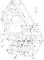
- FIG. 7A , 7B , and 7C an illustrative embodiment of a guide plate 572 coupled to the document platen 500 is shown.
- the guide plate 572 is one non-limiting example of a document support sub-system. Elements of Figures 7A , 7B , and 7C that are analogous to elements in Figure 1 have been shown by indexing the reference numerals by 400.
- the guide plate 572 is positionable adjacent the first side 507 of the document platen 500 to form a document passage 574 between the guide plate 572 and the first side 507 of the document platen 500.
- the document 502 may pass through the document passage 574 as the document 502 moves in its direction of travel 503.
- the guide plate 572 may have an entry side 575 that curves away from the document platen 500. This curved entry side 575 may provide a tapered transition into the document passage 574, and help prevent the document 502 from being jammed or blocked from entering the document passage 574. Entry of the document 502 into the document passage 574 may be further facilitated by the tapered entry edge 528, which has been described above.
- the guide plate 572 is coupled or attached to the document platen 500.
- the guide plate 572 may include a support lip 576 that protrudes from the top side 577 of the guide plate 572.
- the support lip 576 may protrude toward the document platen 500 when the guide plate 572 is in position adjacent the first side 507 of the document platen 500, as shown in Figures 7A-C .
- the support lip 576 may be attachable to the top side 578 of the document platen 500 in any manner, including, but not limited to, using bolts, screws, glue, welding, interference fits, etc.
- the guide plate 572 may be attached to any portion of the document platen 500 that still allows for a document passage 574. In yet another embodiment, the guide plate 572 may not be attached to the document platen 500 at all while still creating a document passage 574,
- Coupled may include coupling via a separate object and may also include direct coupling.
- the term “coupled” may also encompass two or more components that are continuous with one another by virtue of each of the components being formed from the same piece of material, Also, the term “coupled” may include chemical, such as via a chemical bond, mechanical, thermal, magnetic, or electrical coupling.
- the guide plate 572 may also include an entry roller cutaway 580 on the entry side 575 of the guide plate 572, as well as an exit roller cutaway 581 on the exit side 582.
- the entry and exit roller cutaways 580, 581 may each be adapted to receive at least a portion of a roller located on an outer side 583 of the guide plate 572. Although such rollers are not shown in Figure 7A-C , non-limiting examples of such rollers are shown in Figures 8 through 11 .
- the rollers that are at least partially received by the entry and exit roller cutaways 580, 581 may be used to motivate the document 502 through the document passage 574 in the document's direction of travel 503.
- rollers may supplement the motivational force provided by the first and second rollers 522, 523 that are located in the document platen 500.
- the entry and exit roller cutaways 580, 581 may be any shape permitting at least partial entry of an object that provides a motivating force to the document 502, and may be located anywhere on the guide plate 572 where such motivating force to the document 502 may be applied.
- the document platen 500 may have any number of rollers to facilitate movement of the document 502, and these rollers may be placed at various positions on the document platen 500.
- the document platen 500 may have one or more rollers located only on either the entry portion or the exit portion of the document platen 500.
- the document platen 500 may have no rollers at all.
- the guide plate 572 may also include a guide plate aperture 584 that may allow electron-iagnetic radiation therethrough or allow an imaging device to take an image of at least a portion of the document 502 within the document passage 574.
- the guide plate aperture 584 may be substantially coincident with the aperture 506 of the document platen 500,
- the guide plate aperture 584 may also have a substantially similar shape and orientation as the aperture 506 of the document platen 500,
- the guide plate aperture 584 may be offset from the aperture 506 of the document platen 500, or may have a different shape.
- the guide plate 572 may have no aperture at all.
- the guide plate 572 may be formed from any material, including, but not limited to, metal, plastic, synthetics, rubber, etc. In one non-limiting example, the guide plate 572 may be formed from aluminum 6061-T6 or other equivalent material. Indeed, any of the parts or elements described herein may be formed from the aforementioned materials, including aluminum 6061-T6 or other equivalent material. In one illustrative embodiment, the guide plate 572 may also have a finish or coating.
- the outer side 583 or inner side (which forms part of the document passage 574) of the guide plate 572, the curved entry side 575, the exit side 582, the support lip 576, the edges of the guide plate aperture 584, or any other portion of the guide plate 572 may be coated or covered with a finish or coating.
- a finish or coating include black anodized or any other non-reflective material (e.g., paint, adhesive material, or any other substance that will not reflect electromagnetic radiation or light).
- the coating or finish may be a reflective material.
- the guide plate 572 may also be stabilized or mounted using mounting tabs 585a, 585b.
- an illustrative embodiment of the document guide system 636 includes two electromagnetic radiation sources 658a, 658b and the imaging device 654 arranged in a reflective illumination and image capturing system similar to that described in Figures 5 and 6 .
- Elements of Figures 8 , 9A , and 9B that are analogous to elements in Figures 1-7 have been shown by indexing the reference numerals by multiples of 100.
- the imaging device 654 may capture one or more images of at least a portion of the document 602 as it moves in its direction of travel 603 using electromagnetic radiation emitted from either or both of the first and second electromagnetic radiation sources 658a, 658b and reflected off a surface of the document 602.
- the varying angles, positions, and configurations for the electromagnetic radiation sources 658a, 658b and the imaging device 654 described in Figures 5 and 6 may also apply to this embodiment,
- the document 602 may be sandwiched between belts 662 and 663.
- the belt 663 may diverge behind the electromagnetic radiation sources 658a, 658b and the imaging device 654 via roller 666g, the first roller 622, rollers 666h-k, the second roller 623, and the roller 6661.
- the belt 663 may again converge with the belt 662.
- the belt 662 passes through the document passage 674 formed by the guide plate 672 and the document platen 600, which has been described above in Figure 7A , 7B , and 7C .
- the belt 662 may also be motivated to move in the same direction of travel 603 as the document 602 by the rollers 666a, 666m, 666n, and 666f.
- the belt 662 holds the document 602 against the first side 607 of the document platen 600 while the rollers 666a, 666m, 666n, and 666f move the belt 662 through the document passage 674 to cause the document 602 to move through the document passage 674 in its direction of travel 603,
- rollers 666m and 666n are at least partially received by the entry roller cutaway 680 and the exit roller cutaway 681, respectively, thus allowing the rollers 666m and 666n to make contact with the belt 662.
- the rollers 666m and 666n may make direct contact with the document 602, instead of via the belt 662, to motivate the document 602 through the document passage 674.
- the rollers 622 and 623 may be used to motivate the document 602 in its direction of travel 603.
- the document platen 600 may have any number of rollers to facilitate movement of the document 602, and these rollers may be placed at various positions on the document platen 600,
- the document platen 600 may have one or more rollers located only on either the entry portion or the exit portion of the document platen 600, In yet another embodiment, the document platen 600 may have no rollers at all.
- Figures 8 , 9A , and 9B show the guide plate 672 to have a guide plate aperture
- the guide plate 672 may lack the guide plate aperture.
- the aperture in the guide plate 672 may not be needed due to the utilization of reflective illumination and image capturing on the same side of the document platen 600, as shown in Figures 8 , 9A , 9B .
- an illustrative embodiment of the document guide system 736 includes the imaging device 754 and the electromagnetic radiation source 758 used to capture one or more images of the document 702 as it moves in its direction of travel 703 between the guide plate 772 and the document platen 700,
- the document guide system 736 uses electromagnetic radiation emitted from the electromagnetic radiation source 758 and transmitted through the document 702 to the imaging device 754 so that the imaging device 754 can take one or more images of the document 702 as it passes through the document passage 774 formed by the guide plate 772 and the document platen 700.
- the use of transmissive illumination may be similar, in some respects, to the transmissive document guide system 336 described in Figures 3 , 4A , and 4B ,
- the guide plate 772 has the guide plate aperture 784 that is coincident with the aperture 706 of the document platen 700 so that electromagnetic radiation transmitted by the electromagnetic radiation source 758 is able to travel to the imaging device 754.
- the roller 766in and 766n may be partially received by the entry and exit roller cutaways 780, 781, respectively, to motivate the document 702 through the document passage 774.
- the belt 762 does not move fully through the document passage 774, and is instead diverted behind the electromagnetic radiation source 758 using multiple rollers.
- the document platen 700 may have any number of rollers to facilitate movement of the document 702, and these rollers may be placed at various positions on the document platen 700.
- the document platen 700 may have one or more rollers located only on either the entry portion or the exit portion of the document platen 700.
- the document platen 700 may have no rollers at all.
Landscapes
- Engineering & Computer Science (AREA)
- Multimedia (AREA)
- Signal Processing (AREA)
- Health & Medical Sciences (AREA)
- General Health & Medical Sciences (AREA)
- Toxicology (AREA)
- Mechanical Engineering (AREA)
- Physics & Mathematics (AREA)
- General Physics & Mathematics (AREA)
- Facsimile Scanning Arrangements (AREA)
- Apparatus For Radiation Diagnosis (AREA)
Claims (14)
- Dokumentführungssystem unter Verwendung einer Dokumentplatte (100), wobei das Dokumentführungssystem umfasst:eine Dokumentplatte (100), die eine erste Seite (107), die dem Dokument zugewandt ist, und eine zweite, entgegengesetzten Seite (108) aufweist; undein Dokument-Trägersubsystem (238) angrenzend an die erste Seite (107) der Dokumentplatte (100);wobei das Dokument-Trägersubsystem (238) und die erste Seite (107) der Dokumentplatte (100) angepasst sind, ein Dokument (102) dazwischen zu empfangen; undwobei die Dokumentplatte (100) eine Öffnung (106) bildet, die angepasst ist, elektromagnetische Strahlung dort hindurch zu lassen;dadurch gekennzeichnet, dass:die zweite Seite (108) der Dokumentplatte (100) einen Einschnitt (110) mit gewinkelten Seiten (112, 113) bildet, wobei sich die Öffnung (106) in ca. einem Scheitelpunkt (111) des Einschnitts (110) befindet.
- Dokumentführungssystem nach Anspruch 1, wobei die Dokumentplatte eine Eingangskante und eine Ausgangskante aufweist, wobei das Dokumentführungssystem angepasst ist, das Dokument aufzunehmen, um eine Bewegungsrichtung ab der Eingangskante zur Ausgangskante der Dokumentplatte zu haben; und
wobei die Öffnung ein länglicher Schlitz im Wesentlichen senkrecht zur Bewegungsrichtung des Dokuments ist. - Dokumentführungssystem nach Anspruch 1, wobei die gewinkelten Seiten (112, 113) des Einschnitts (110) in der Dokumentplatte (100) eine erste gewinkelte Seite (112) und eine zweite gewinkelte Seite (113) aufweisen;
wobei die erste gewinkelte Seite (112) und die erste Seite (107) der Dokumentplatte (100) einen ersten Winkel (114) bilden, wobei der erste Winkel (114) in einem Bereich von 10 bis 80 Grad liegt; und
wobei die zweite gewinkelte Seite (113) und die erste Seite (107) der Dokumentplatte (100) einen zweiten Winkel (115) bilden, wobei der zweite Winkel (115) in einem Bereich von 10 bis 80 Grad liegt. - Dokumentführungssystem nach einem der Ansprüche 1 bis 3, wobei das Dokument-Trägersubsystem (238) umfasst: ein oder mehrere Bänder (240, 241) zum Halten des Dokuments (102) gegen die erste Seite (107) der Dokumentplatte (100), wenn sich das Dokument (102) entlang der ersten Seite (107) der Dokumentplatte (100) und zwischen dem einen oder den mehreren Bändern (240, 241) und der ersten Seite (107) der Dokumentplatte (100) bewegt.
- Dokumentführungssystem nach Anspruch 4, wobei die Dokumentplatte (100) eine Eingangskante (104) und eine Ausgangskante (105) aufweist;
wobei das Dokumentführungssystem angepasst ist, das Dokument (102) aufzunehmen, um eine Bewegungsrichtung von der Eingangskante (104) zur Ausgangskante (105) der Dokumentplatte (100) zu haben; und
wobei das eine oder die mehreren Bändern (240, 241) drehbar sind, um das Dokument (102) entlang der ersten Seite der Dokumentplatte (100) in der Bewegungsrichtung (103) des Dokuments zu bewegen. - Dokumentführungssystem nach einem der Ansprüche 1 bis 5, wobei die Dokumentplatte (100) eine verjüngte Eingangskante (128) aufweist, um das Dokument (102) in einen Raum zwischen dem Dokument-Trägersubsystem (238) und der ersten Seite (107) der Dokumentplatte (100) einzuführen.
- Dokumentführungssystem nach einem der Ansprüche 1 bis 6, wobei die Dokumentplatte (100) einen Eingangsabschnitt (124) und einen Ausgangsabschnitt (125) aufweist, wobei das Dokument angepasst ist, eine Bewegungsrichtung (103) vom Eingangsabschnitt (124) zum Ausgangsabschnitt (125) der Dokumentplatte (100) zu haben;
wobei die Dokumentplatte (100) umfasst:eine erste Rolle (122) am Eingangsabschnitt (124) der Dokumentplatte (100); und eine zweite Rolle (123) am Ausgangsabschnitt (125) der Dokumentplatte (100); undwobei die erste Rolle (122) und die zweite Rolle (123) drehbar sind, um Bewegung des Dokuments (102) in der Bewegungsrichtung (103) des Dokuments zu erleichtern. - Dokumentführungssystem nach einem der Ansprüche 1 bis 7, wobei das Dokument-Trägersubsystem (238) umfasst:eine Führungsplatte (572), die angrenzend an die erste Seite (107) der Dokumentplatte (100) positionierbar ist, um einen Dokumentdurchgang zwischen der Führungsplatte (572) und der ersten Seite (107) der Dokumentplatte (100) zu bilden.
- Dokumentführungssystem nach Anspruch 8, wobei die Führungsplatte (572) eine Führungsplattenöffnung (584) bildet, um elektromagnetische Strahlung dort hindurch zu lassen, wobei die Führungsplattenöffnung (584) im Wesentlichen mit der Öffnung (106) übereinstimmt, die von der Dokumentplatte (100) gebildet ist.
- Dokumentführungssystem nach einem der Ansprüche 8 oder 9, wobei die Führungsplatte (572) eine Eingangsseite (575) aufweist, wobei sich die Eingangsseite der Führungsplatte (572) von der Dokumentplatte (100) weg biegt, um den Eintritt des Dokuments (102) in den Dokumentdurchgang zu führen.
- Dokumentführungssystem nach einem der Ansprüche 8 bis 10, wobei die Führungsplatte (572) eine Eingangsseite (575) und eine Ausgangsseite (582) aufweist;
wobei die Eingangsseite (575) der Führungsplatte einen Ausschnitt (580) für die Eingangsrolle bildet;
wobei die Ausgangsseite (582) der Führungsplatte einen Ausschnitt (581) für die Ausgangsrolle bildet; und
wobei der Ausschnitt (580) für die Eingangsrolle und der Ausschnitt (581) für die Ausgangsrolle jeweils angepasst sind, eine Rolle mindestens teilweise aufzunehmen, um das Dokument (102) durch den Dokumentdurchgang zu bewegen; und wobei vorzugsweise:das Dokumentführungssystem angepasst ist, das Dokument (102) aufzunehmen, um eine Bewegungsrichtung (103) von der Eingangsseite (575) zur Ausgangsseite (582) der Führungsplatte (572) zu haben, wobei das Dokumentführungssystem ferner umfasst:ein Band (662), um das Dokument (102) gegen die erste Seite (107) der Dokumentplatte (100) zu halten, wobei die Rollen drehbar sind, um das Band (662) durch den Dokumentdurchgang zu bewegen, dadurch wird bewirkt, dass sich das Dokument (102) in der Bewegungsrichtung (103) des Dokuments durch den Dokumentdurchgang bewegt. - Dokumentführungssystem nach einem der Ansprüche 1 bis 11, ferner umfassend:eine oder mehrere elektromagnetische Strahlungsquellen (758), die auf die Öffnung (106) der Dokumentplatte (100) gezielt sind, um mindestens einen Abschnitt des Dokuments (102) an der Öffnung (106) der Dokumentplatte (100) zu beleuchten; undein Bildgerät (754), dass auf die Öffnung (106) der Dokumentplatte (100) gezielt ist, um ein Bild von mindestens einem Abschnitt des Dokuments an der Öffnung (106) der Dokumentplatte (100) zu erfassen.
- Dokumentführungssystem nach Anspruch 12, wobei entweder die eine oder mehrere der elektromagnetischen Strahlungsquellen (758) und das Bildgerät (754) auf der gleichen Seite der Dokumentplatte (100) positioniert sind; oder die eine oder mehreren elektromagnetischen Strahlungsquellen (758) auf der entgegengesetzten Seite der Dokumentplatte (100) als das Bildgerät (754) positioniert sind.
- Dokumentführungssystem nach einem der Ansprüche 1 bis 13, ferner umfassend:ein oder mehrere Bänder (662), um das Dokument (102) entlang der ersten Seite der Dokumentplatte (100) derartig zu bewegen, dass sich das Dokument (102) mindestens teilweise über die Öffnung bewegt.
Applications Claiming Priority (2)
| Application Number | Priority Date | Filing Date | Title |
|---|---|---|---|
| US13/327,430 US8585053B2 (en) | 2011-12-15 | 2011-12-15 | Document guide systems and methods employing a document platen |
| PCT/US2012/069128 WO2013090352A1 (en) | 2011-12-15 | 2012-12-12 | Document guide systems and methods employing a document platen |
Publications (3)
| Publication Number | Publication Date |
|---|---|
| EP2791920A1 EP2791920A1 (de) | 2014-10-22 |
| EP2791920A4 EP2791920A4 (de) | 2016-01-27 |
| EP2791920B1 true EP2791920B1 (de) | 2018-04-04 |
Family
ID=48609331
Family Applications (1)
| Application Number | Title | Priority Date | Filing Date |
|---|---|---|---|
| EP12858113.9A Not-in-force EP2791920B1 (de) | 2011-12-15 | 2012-12-12 | Dokumentführungssysteme und verfahren mit einem dokumentvorlageplatte |
Country Status (5)
| Country | Link |
|---|---|
| US (2) | US8585053B2 (de) |
| EP (1) | EP2791920B1 (de) |
| CN (1) | CN104106100A (de) |
| IN (1) | IN2014DN05832A (de) |
| WO (1) | WO2013090352A1 (de) |
Families Citing this family (7)
| Publication number | Priority date | Publication date | Assignee | Title |
|---|---|---|---|---|
| US8585053B2 (en) * | 2011-12-15 | 2013-11-19 | De La Rue North America Inc. | Document guide systems and methods employing a document platen |
| DE102015006667A1 (de) * | 2015-05-22 | 2016-11-24 | Giesecke & Devrient Gmbh | Vorrichtung zum Bearbeiten von Blattgut |
| US10212304B2 (en) * | 2017-01-17 | 2019-02-19 | Xerox Corporation | Document scanner |
| CN107954228B (zh) * | 2017-11-30 | 2024-03-26 | 双钱集团(江苏)轮胎有限公司 | 一种轮胎胶片冷却提升装置 |
| EP3721419B1 (de) | 2017-12-07 | 2024-10-16 | Crane Payment Innovations, Inc. | Offenes banknotenpfadsystem |
| JP7124310B2 (ja) * | 2017-12-14 | 2022-08-24 | コニカミノルタ株式会社 | 用紙種類判別装置及び画像形成装置 |
| US20230185839A1 (en) * | 2021-12-15 | 2023-06-15 | Insurance Services Office, Inc. | Computer Vision Systems and Methods for Segmenting and Classifying Building Components, Contents, Materials, and Attributes |
Family Cites Families (18)
| Publication number | Priority date | Publication date | Assignee | Title |
|---|---|---|---|---|
| US4316667A (en) | 1980-02-19 | 1982-02-23 | International Business Machines Corporation | Copier and recirculating document feeder |
| JPS6455763U (de) * | 1987-09-30 | 1989-04-06 | ||
| JPH05300340A (ja) * | 1992-04-21 | 1993-11-12 | Eastman Kodak Japan Kk | 画像入力装置 |
| US5732148A (en) * | 1994-09-16 | 1998-03-24 | Keagy; John Martin | Apparatus and method for electronically acquiring fingerprint images with low cost removable platen and separate imaging device |
| CN1157927C (zh) | 1996-10-23 | 2004-07-14 | 西铁城时计株式会社 | 用于读字符和图象数据的设备 |
| JPH11217136A (ja) * | 1997-11-20 | 1999-08-10 | Fuji Photo Film Co Ltd | ガイド板およびこれを用いる画像記録媒体搬送装置 |
| US6209861B1 (en) | 1998-03-11 | 2001-04-03 | Kyocera Mita Corporation | Sheet transport device and automatic document feeder |
| FR2790997B1 (fr) * | 1999-03-16 | 2001-06-01 | Secap | Dispositif pour imprimer un signe et machine a affranchir le comportant |
| US20030030854A1 (en) | 2001-08-10 | 2003-02-13 | Yin-Chun Huang | Focusing apparatus of an automatic document feeder |
| US6585261B2 (en) * | 2001-09-14 | 2003-07-01 | Ncr Corporation | Track bottom apparatus for use in a document processing system |
| US6964414B2 (en) * | 2003-09-24 | 2005-11-15 | Xerox Corporation | Jam clearance in a vertical sheet transport in a printing apparatus |
| TWI276597B (en) | 2006-01-05 | 2007-03-21 | Avision Inc | Automatic document feeder having a document control roller |
| US7703767B2 (en) * | 2006-11-16 | 2010-04-27 | De La Rue North America, Inc. | Inertial flattening for note processing |
| KR100961575B1 (ko) * | 2007-12-13 | 2010-06-04 | 노틸러스효성 주식회사 | 종이매체 이송장치 및 이를 구비한 금융자동화기기 |
| JP4646008B2 (ja) * | 2008-06-30 | 2011-03-09 | 株式会社沖データ | 媒体搬送装置及び画像形成装置 |
| JP2010206632A (ja) * | 2009-03-04 | 2010-09-16 | Ricoh Co Ltd | 画像読取装置、及び複写機 |
| JP5306025B2 (ja) * | 2009-04-02 | 2013-10-02 | キヤノン株式会社 | シート搬送装置及び電子写真装置 |
| US8585053B2 (en) * | 2011-12-15 | 2013-11-19 | De La Rue North America Inc. | Document guide systems and methods employing a document platen |
-
2011
- 2011-12-15 US US13/327,430 patent/US8585053B2/en not_active Expired - Fee Related
-
2012
- 2012-12-12 EP EP12858113.9A patent/EP2791920B1/de not_active Not-in-force
- 2012-12-12 CN CN201280069090.9A patent/CN104106100A/zh active Pending
- 2012-12-12 WO PCT/US2012/069128 patent/WO2013090352A1/en not_active Ceased
-
2013
- 2013-10-29 US US14/066,347 patent/US20140049002A1/en not_active Abandoned
-
2014
- 2014-07-11 IN IN5832DEN2014 patent/IN2014DN05832A/en unknown
Non-Patent Citations (1)
| Title |
|---|
| None * |
Also Published As
| Publication number | Publication date |
|---|---|
| US8585053B2 (en) | 2013-11-19 |
| EP2791920A1 (de) | 2014-10-22 |
| US20140049002A1 (en) | 2014-02-20 |
| WO2013090352A1 (en) | 2013-06-20 |
| CN104106100A (zh) | 2014-10-15 |
| IN2014DN05832A (de) | 2015-05-15 |
| US20130154181A1 (en) | 2013-06-20 |
| EP2791920A4 (de) | 2016-01-27 |
Similar Documents
| Publication | Publication Date | Title |
|---|---|---|
| US8585053B2 (en) | Document guide systems and methods employing a document platen | |
| EP1492057B1 (de) | Blatt-Transportvorrichtung | |
| US11173522B2 (en) | Device for sorting used beverage or food containers | |
| US6962291B2 (en) | Device for automatically receiving, scanning and handling containers | |
| US7344016B2 (en) | Method and device for orienting flat items of mail towards a narrow edge | |
| US7611141B2 (en) | Top registered item transport system | |
| JP6764367B2 (ja) | 紙葉類斜行補正装置 | |
| RU2009123394A (ru) | Инерционное выравнивание банкнот в процессе их обработки | |
| CN100573545C (zh) | 射频识别标签检测平台 | |
| US20030115071A1 (en) | Method of operating an image-based document processing system and an apparatus therefor | |
| JP2014087965A (ja) | 搬送装置及び記録装置 | |
| US20140210161A1 (en) | Valuable file identification device | |
| US20190206172A1 (en) | Sheet identification device and sheet identification method | |
| US7503562B2 (en) | Apparatus for processing sheet material | |
| JP2013246106A (ja) | 搬送ユニット、搬送装置、および検査装置 | |
| CN103916564B (zh) | 光学式读取装置 | |
| KR101358109B1 (ko) | 대상물 안내 기능을 갖는 비전 검사 장치 | |
| KR101909111B1 (ko) | 엘이디 장착 프레임용 반사필름 부착장치 | |
| JP2004234201A (ja) | 磁気検知装置 | |
| JP2004358954A (ja) | 製品の縁の位置を検出する装置および方法 | |
| EP1710995A1 (de) | Schneller Scanner mit drehbarem Spiegel und Bildverarbeitungssystem | |
| CN121724042A (zh) | 一种卡片检测装置及其检测方法 | |
| US10000078B2 (en) | Printer apparatus | |
| KR101534405B1 (ko) | 스캔 장치 | |
| US3522438A (en) | Optical scanning device having plural illuminating devices and a light sink for each such device to reduce the effect of the devices which are not instantaneously in use |
Legal Events
| Date | Code | Title | Description |
|---|---|---|---|
| PUAI | Public reference made under article 153(3) epc to a published international application that has entered the european phase |
Free format text: ORIGINAL CODE: 0009012 |
|
| 17P | Request for examination filed |
Effective date: 20140627 |
|
| AK | Designated contracting states |
Kind code of ref document: A1 Designated state(s): AL AT BE BG CH CY CZ DE DK EE ES FI FR GB GR HR HU IE IS IT LI LT LU LV MC MK MT NL NO PL PT RO RS SE SI SK SM TR |
|
| DAX | Request for extension of the european patent (deleted) | ||
| RIC1 | Information provided on ipc code assigned before grant |
Ipc: G07D 13/00 20060101AFI20150907BHEP Ipc: H04N 1/12 20060101ALI20150907BHEP Ipc: B65H 43/08 20060101ALI20150907BHEP Ipc: B65H 5/06 20060101ALI20150907BHEP Ipc: B65H 7/14 20060101ALI20150907BHEP |
|
| RA4 | Supplementary search report drawn up and despatched (corrected) |
Effective date: 20160107 |
|
| RIC1 | Information provided on ipc code assigned before grant |
Ipc: B65H 7/14 20060101ALI20151222BHEP Ipc: B65H 43/08 20060101ALI20151222BHEP Ipc: H04N 1/12 20060101ALI20151222BHEP Ipc: B65H 5/06 20060101ALI20151222BHEP Ipc: G07D 13/00 20060101AFI20151222BHEP |
|
| GRAP | Despatch of communication of intention to grant a patent |
Free format text: ORIGINAL CODE: EPIDOSNIGR1 |
|
| INTG | Intention to grant announced |
Effective date: 20171024 |
|
| GRAS | Grant fee paid |
Free format text: ORIGINAL CODE: EPIDOSNIGR3 |
|
| GRAA | (expected) grant |
Free format text: ORIGINAL CODE: 0009210 |
|
| GRAT | Correction requested after decision to grant or after decision to maintain patent in amended form |
Free format text: ORIGINAL CODE: EPIDOSNCDEC |
|
| AK | Designated contracting states |
Kind code of ref document: B1 Designated state(s): AL AT BE BG CH CY CZ DE DK EE ES FI FR GB GR HR HU IE IS IT LI LT LU LV MC MK MT NL NO PL PT RO RS SE SI SK SM TR |
|
| REG | Reference to a national code |
Ref country code: GB Ref legal event code: FG4D |
|
| REG | Reference to a national code |
Ref country code: CH Ref legal event code: EP |
|
| REG | Reference to a national code |
Ref country code: AT Ref legal event code: REF Ref document number: 986374 Country of ref document: AT Kind code of ref document: T Effective date: 20180415 |
|
| REG | Reference to a national code |
Ref country code: IE Ref legal event code: FG4D |
|
| REG | Reference to a national code |
Ref country code: DE Ref legal event code: R096 Ref document number: 602012044898 Country of ref document: DE |
|
| REG | Reference to a national code |
Ref country code: NL Ref legal event code: MP Effective date: 20180404 |
|
| REG | Reference to a national code |
Ref country code: LT Ref legal event code: MG4D |
|
| PG25 | Lapsed in a contracting state [announced via postgrant information from national office to epo] |
Ref country code: NL Free format text: LAPSE BECAUSE OF FAILURE TO SUBMIT A TRANSLATION OF THE DESCRIPTION OR TO PAY THE FEE WITHIN THE PRESCRIBED TIME-LIMIT Effective date: 20180404 |
|
| PG25 | Lapsed in a contracting state [announced via postgrant information from national office to epo] |
Ref country code: ES Free format text: LAPSE BECAUSE OF FAILURE TO SUBMIT A TRANSLATION OF THE DESCRIPTION OR TO PAY THE FEE WITHIN THE PRESCRIBED TIME-LIMIT Effective date: 20180404 Ref country code: AL Free format text: LAPSE BECAUSE OF FAILURE TO SUBMIT A TRANSLATION OF THE DESCRIPTION OR TO PAY THE FEE WITHIN THE PRESCRIBED TIME-LIMIT Effective date: 20180404 Ref country code: BG Free format text: LAPSE BECAUSE OF FAILURE TO SUBMIT A TRANSLATION OF THE DESCRIPTION OR TO PAY THE FEE WITHIN THE PRESCRIBED TIME-LIMIT Effective date: 20180704 Ref country code: NO Free format text: LAPSE BECAUSE OF FAILURE TO SUBMIT A TRANSLATION OF THE DESCRIPTION OR TO PAY THE FEE WITHIN THE PRESCRIBED TIME-LIMIT Effective date: 20180704 Ref country code: LT Free format text: LAPSE BECAUSE OF FAILURE TO SUBMIT A TRANSLATION OF THE DESCRIPTION OR TO PAY THE FEE WITHIN THE PRESCRIBED TIME-LIMIT Effective date: 20180404 Ref country code: FI Free format text: LAPSE BECAUSE OF FAILURE TO SUBMIT A TRANSLATION OF THE DESCRIPTION OR TO PAY THE FEE WITHIN THE PRESCRIBED TIME-LIMIT Effective date: 20180404 Ref country code: SE Free format text: LAPSE BECAUSE OF FAILURE TO SUBMIT A TRANSLATION OF THE DESCRIPTION OR TO PAY THE FEE WITHIN THE PRESCRIBED TIME-LIMIT Effective date: 20180404 Ref country code: PL Free format text: LAPSE BECAUSE OF FAILURE TO SUBMIT A TRANSLATION OF THE DESCRIPTION OR TO PAY THE FEE WITHIN THE PRESCRIBED TIME-LIMIT Effective date: 20180404 |
|
| PG25 | Lapsed in a contracting state [announced via postgrant information from national office to epo] |
Ref country code: HR Free format text: LAPSE BECAUSE OF FAILURE TO SUBMIT A TRANSLATION OF THE DESCRIPTION OR TO PAY THE FEE WITHIN THE PRESCRIBED TIME-LIMIT Effective date: 20180404 Ref country code: LV Free format text: LAPSE BECAUSE OF FAILURE TO SUBMIT A TRANSLATION OF THE DESCRIPTION OR TO PAY THE FEE WITHIN THE PRESCRIBED TIME-LIMIT Effective date: 20180404 Ref country code: GR Free format text: LAPSE BECAUSE OF FAILURE TO SUBMIT A TRANSLATION OF THE DESCRIPTION OR TO PAY THE FEE WITHIN THE PRESCRIBED TIME-LIMIT Effective date: 20180705 Ref country code: RS Free format text: LAPSE BECAUSE OF FAILURE TO SUBMIT A TRANSLATION OF THE DESCRIPTION OR TO PAY THE FEE WITHIN THE PRESCRIBED TIME-LIMIT Effective date: 20180404 |
|
| REG | Reference to a national code |
Ref country code: AT Ref legal event code: MK05 Ref document number: 986374 Country of ref document: AT Kind code of ref document: T Effective date: 20180404 |
|
| PG25 | Lapsed in a contracting state [announced via postgrant information from national office to epo] |
Ref country code: PT Free format text: LAPSE BECAUSE OF FAILURE TO SUBMIT A TRANSLATION OF THE DESCRIPTION OR TO PAY THE FEE WITHIN THE PRESCRIBED TIME-LIMIT Effective date: 20180806 |
|
| REG | Reference to a national code |
Ref country code: DE Ref legal event code: R097 Ref document number: 602012044898 Country of ref document: DE |
|
| PG25 | Lapsed in a contracting state [announced via postgrant information from national office to epo] |
Ref country code: CZ Free format text: LAPSE BECAUSE OF FAILURE TO SUBMIT A TRANSLATION OF THE DESCRIPTION OR TO PAY THE FEE WITHIN THE PRESCRIBED TIME-LIMIT Effective date: 20180404 Ref country code: RO Free format text: LAPSE BECAUSE OF FAILURE TO SUBMIT A TRANSLATION OF THE DESCRIPTION OR TO PAY THE FEE WITHIN THE PRESCRIBED TIME-LIMIT Effective date: 20180404 Ref country code: SK Free format text: LAPSE BECAUSE OF FAILURE TO SUBMIT A TRANSLATION OF THE DESCRIPTION OR TO PAY THE FEE WITHIN THE PRESCRIBED TIME-LIMIT Effective date: 20180404 Ref country code: DK Free format text: LAPSE BECAUSE OF FAILURE TO SUBMIT A TRANSLATION OF THE DESCRIPTION OR TO PAY THE FEE WITHIN THE PRESCRIBED TIME-LIMIT Effective date: 20180404 Ref country code: AT Free format text: LAPSE BECAUSE OF FAILURE TO SUBMIT A TRANSLATION OF THE DESCRIPTION OR TO PAY THE FEE WITHIN THE PRESCRIBED TIME-LIMIT Effective date: 20180404 Ref country code: EE Free format text: LAPSE BECAUSE OF FAILURE TO SUBMIT A TRANSLATION OF THE DESCRIPTION OR TO PAY THE FEE WITHIN THE PRESCRIBED TIME-LIMIT Effective date: 20180404 |
|
| PLBE | No opposition filed within time limit |
Free format text: ORIGINAL CODE: 0009261 |
|
| STAA | Information on the status of an ep patent application or granted ep patent |
Free format text: STATUS: NO OPPOSITION FILED WITHIN TIME LIMIT |
|
| PG25 | Lapsed in a contracting state [announced via postgrant information from national office to epo] |
Ref country code: IT Free format text: LAPSE BECAUSE OF FAILURE TO SUBMIT A TRANSLATION OF THE DESCRIPTION OR TO PAY THE FEE WITHIN THE PRESCRIBED TIME-LIMIT Effective date: 20180404 Ref country code: SM Free format text: LAPSE BECAUSE OF FAILURE TO SUBMIT A TRANSLATION OF THE DESCRIPTION OR TO PAY THE FEE WITHIN THE PRESCRIBED TIME-LIMIT Effective date: 20180404 |
|
| 26N | No opposition filed |
Effective date: 20190107 |
|
| PG25 | Lapsed in a contracting state [announced via postgrant information from national office to epo] |
Ref country code: SI Free format text: LAPSE BECAUSE OF FAILURE TO SUBMIT A TRANSLATION OF THE DESCRIPTION OR TO PAY THE FEE WITHIN THE PRESCRIBED TIME-LIMIT Effective date: 20180404 |
|
| REG | Reference to a national code |
Ref country code: DE Ref legal event code: R119 Ref document number: 602012044898 Country of ref document: DE |
|
| REG | Reference to a national code |
Ref country code: CH Ref legal event code: PL |
|
| GBPC | Gb: european patent ceased through non-payment of renewal fee |
Effective date: 20181212 |
|
| PG25 | Lapsed in a contracting state [announced via postgrant information from national office to epo] |
Ref country code: MC Free format text: LAPSE BECAUSE OF FAILURE TO SUBMIT A TRANSLATION OF THE DESCRIPTION OR TO PAY THE FEE WITHIN THE PRESCRIBED TIME-LIMIT Effective date: 20180404 Ref country code: LU Free format text: LAPSE BECAUSE OF NON-PAYMENT OF DUE FEES Effective date: 20181212 |
|
| REG | Reference to a national code |
Ref country code: IE Ref legal event code: MM4A |
|
| REG | Reference to a national code |
Ref country code: BE Ref legal event code: MM Effective date: 20181231 |
|
| PG25 | Lapsed in a contracting state [announced via postgrant information from national office to epo] |
Ref country code: DE Free format text: LAPSE BECAUSE OF NON-PAYMENT OF DUE FEES Effective date: 20190702 Ref country code: FR Free format text: LAPSE BECAUSE OF NON-PAYMENT OF DUE FEES Effective date: 20181231 Ref country code: IE Free format text: LAPSE BECAUSE OF NON-PAYMENT OF DUE FEES Effective date: 20181212 |
|
| PG25 | Lapsed in a contracting state [announced via postgrant information from national office to epo] |
Ref country code: BE Free format text: LAPSE BECAUSE OF NON-PAYMENT OF DUE FEES Effective date: 20181231 |
|
| PG25 | Lapsed in a contracting state [announced via postgrant information from national office to epo] |
Ref country code: CH Free format text: LAPSE BECAUSE OF NON-PAYMENT OF DUE FEES Effective date: 20181231 Ref country code: GB Free format text: LAPSE BECAUSE OF NON-PAYMENT OF DUE FEES Effective date: 20181212 Ref country code: LI Free format text: LAPSE BECAUSE OF NON-PAYMENT OF DUE FEES Effective date: 20181231 |
|
| PG25 | Lapsed in a contracting state [announced via postgrant information from national office to epo] |
Ref country code: MT Free format text: LAPSE BECAUSE OF NON-PAYMENT OF DUE FEES Effective date: 20181212 |
|
| PG25 | Lapsed in a contracting state [announced via postgrant information from national office to epo] |
Ref country code: TR Free format text: LAPSE BECAUSE OF FAILURE TO SUBMIT A TRANSLATION OF THE DESCRIPTION OR TO PAY THE FEE WITHIN THE PRESCRIBED TIME-LIMIT Effective date: 20180404 |
|
| PG25 | Lapsed in a contracting state [announced via postgrant information from national office to epo] |
Ref country code: HU Free format text: LAPSE BECAUSE OF FAILURE TO SUBMIT A TRANSLATION OF THE DESCRIPTION OR TO PAY THE FEE WITHIN THE PRESCRIBED TIME-LIMIT; INVALID AB INITIO Effective date: 20121212 Ref country code: MK Free format text: LAPSE BECAUSE OF NON-PAYMENT OF DUE FEES Effective date: 20180404 Ref country code: CY Free format text: LAPSE BECAUSE OF FAILURE TO SUBMIT A TRANSLATION OF THE DESCRIPTION OR TO PAY THE FEE WITHIN THE PRESCRIBED TIME-LIMIT Effective date: 20180404 |
|
| PG25 | Lapsed in a contracting state [announced via postgrant information from national office to epo] |
Ref country code: IS Free format text: LAPSE BECAUSE OF FAILURE TO SUBMIT A TRANSLATION OF THE DESCRIPTION OR TO PAY THE FEE WITHIN THE PRESCRIBED TIME-LIMIT Effective date: 20180804 |