EP2790985B1 - Weckvorrichtung für eine bremssystemkomponente eines fahrzeugs und verfahren zum wecken mindestens einer bremssystemkomponente eines fahrzeugs - Google Patents
Weckvorrichtung für eine bremssystemkomponente eines fahrzeugs und verfahren zum wecken mindestens einer bremssystemkomponente eines fahrzeugs Download PDFInfo
- Publication number
- EP2790985B1 EP2790985B1 EP12775004.0A EP12775004A EP2790985B1 EP 2790985 B1 EP2790985 B1 EP 2790985B1 EP 12775004 A EP12775004 A EP 12775004A EP 2790985 B1 EP2790985 B1 EP 2790985B1
- Authority
- EP
- European Patent Office
- Prior art keywords
- magnet
- wake
- brake system
- energy consumption
- braking force
- Prior art date
- Legal status (The legal status is an assumption and is not a legal conclusion. Google has not performed a legal analysis and makes no representation as to the accuracy of the status listed.)
- Active
Links
- 238000000034 method Methods 0.000 title claims description 12
- 230000005284 excitation Effects 0.000 title 1
- 230000005540 biological transmission Effects 0.000 claims description 57
- 238000005265 energy consumption Methods 0.000 claims description 44
- 230000006698 induction Effects 0.000 claims description 38
- 239000004020 conductor Substances 0.000 claims description 23
- 230000002618 waking effect Effects 0.000 claims description 3
- 230000001939 inductive effect Effects 0.000 description 3
- 230000004913 activation Effects 0.000 description 2
- 238000006073 displacement reaction Methods 0.000 description 2
- 230000003213 activating effect Effects 0.000 description 1
- 230000015572 biosynthetic process Effects 0.000 description 1
- 238000005516 engineering process Methods 0.000 description 1
- 230000010354 integration Effects 0.000 description 1
- 238000004519 manufacturing process Methods 0.000 description 1
Images


Classifications
-
- B—PERFORMING OPERATIONS; TRANSPORTING
- B60—VEHICLES IN GENERAL
- B60T—VEHICLE BRAKE CONTROL SYSTEMS OR PARTS THEREOF; BRAKE CONTROL SYSTEMS OR PARTS THEREOF, IN GENERAL; ARRANGEMENT OF BRAKING ELEMENTS ON VEHICLES IN GENERAL; PORTABLE DEVICES FOR PREVENTING UNWANTED MOVEMENT OF VEHICLES; VEHICLE MODIFICATIONS TO FACILITATE COOLING OF BRAKES
- B60T17/00—Component parts, details, or accessories of power brake systems not covered by groups B60T8/00, B60T13/00 or B60T15/00, or presenting other characteristic features
- B60T17/18—Safety devices; Monitoring
- B60T17/22—Devices for monitoring or checking brake systems; Signal devices
-
- B—PERFORMING OPERATIONS; TRANSPORTING
- B60—VEHICLES IN GENERAL
- B60T—VEHICLE BRAKE CONTROL SYSTEMS OR PARTS THEREOF; BRAKE CONTROL SYSTEMS OR PARTS THEREOF, IN GENERAL; ARRANGEMENT OF BRAKING ELEMENTS ON VEHICLES IN GENERAL; PORTABLE DEVICES FOR PREVENTING UNWANTED MOVEMENT OF VEHICLES; VEHICLE MODIFICATIONS TO FACILITATE COOLING OF BRAKES
- B60T11/00—Transmitting braking action from initiating means to ultimate brake actuator without power assistance or drive or where such assistance or drive is irrelevant
- B60T11/10—Transmitting braking action from initiating means to ultimate brake actuator without power assistance or drive or where such assistance or drive is irrelevant transmitting by fluid means, e.g. hydraulic
- B60T11/16—Master control, e.g. master cylinders
- B60T11/18—Connection thereof to initiating means
-
- B—PERFORMING OPERATIONS; TRANSPORTING
- B60—VEHICLES IN GENERAL
- B60T—VEHICLE BRAKE CONTROL SYSTEMS OR PARTS THEREOF; BRAKE CONTROL SYSTEMS OR PARTS THEREOF, IN GENERAL; ARRANGEMENT OF BRAKING ELEMENTS ON VEHICLES IN GENERAL; PORTABLE DEVICES FOR PREVENTING UNWANTED MOVEMENT OF VEHICLES; VEHICLE MODIFICATIONS TO FACILITATE COOLING OF BRAKES
- B60T13/00—Transmitting braking action from initiating means to ultimate brake actuator with power assistance or drive; Brake systems incorporating such transmitting means, e.g. air-pressure brake systems
- B60T13/10—Transmitting braking action from initiating means to ultimate brake actuator with power assistance or drive; Brake systems incorporating such transmitting means, e.g. air-pressure brake systems with fluid assistance, drive, or release
- B60T13/66—Electrical control in fluid-pressure brake systems
- B60T13/662—Electrical control in fluid-pressure brake systems characterised by specified functions of the control system components
-
- B—PERFORMING OPERATIONS; TRANSPORTING
- B60—VEHICLES IN GENERAL
- B60T—VEHICLE BRAKE CONTROL SYSTEMS OR PARTS THEREOF; BRAKE CONTROL SYSTEMS OR PARTS THEREOF, IN GENERAL; ARRANGEMENT OF BRAKING ELEMENTS ON VEHICLES IN GENERAL; PORTABLE DEVICES FOR PREVENTING UNWANTED MOVEMENT OF VEHICLES; VEHICLE MODIFICATIONS TO FACILITATE COOLING OF BRAKES
- B60T13/00—Transmitting braking action from initiating means to ultimate brake actuator with power assistance or drive; Brake systems incorporating such transmitting means, e.g. air-pressure brake systems
- B60T13/74—Transmitting braking action from initiating means to ultimate brake actuator with power assistance or drive; Brake systems incorporating such transmitting means, e.g. air-pressure brake systems with electrical assistance or drive
- B60T13/745—Transmitting braking action from initiating means to ultimate brake actuator with power assistance or drive; Brake systems incorporating such transmitting means, e.g. air-pressure brake systems with electrical assistance or drive acting on a hydraulic system, e.g. a master cylinder
-
- B—PERFORMING OPERATIONS; TRANSPORTING
- B60—VEHICLES IN GENERAL
- B60T—VEHICLE BRAKE CONTROL SYSTEMS OR PARTS THEREOF; BRAKE CONTROL SYSTEMS OR PARTS THEREOF, IN GENERAL; ARRANGEMENT OF BRAKING ELEMENTS ON VEHICLES IN GENERAL; PORTABLE DEVICES FOR PREVENTING UNWANTED MOVEMENT OF VEHICLES; VEHICLE MODIFICATIONS TO FACILITATE COOLING OF BRAKES
- B60T7/00—Brake-action initiating means
- B60T7/12—Brake-action initiating means for automatic initiation; for initiation not subject to will of driver or passenger
- B60T7/14—Brake-action initiating means for automatic initiation; for initiation not subject to will of driver or passenger operated upon collapse of driver
-
- B—PERFORMING OPERATIONS; TRANSPORTING
- B60—VEHICLES IN GENERAL
- B60T—VEHICLE BRAKE CONTROL SYSTEMS OR PARTS THEREOF; BRAKE CONTROL SYSTEMS OR PARTS THEREOF, IN GENERAL; ARRANGEMENT OF BRAKING ELEMENTS ON VEHICLES IN GENERAL; PORTABLE DEVICES FOR PREVENTING UNWANTED MOVEMENT OF VEHICLES; VEHICLE MODIFICATIONS TO FACILITATE COOLING OF BRAKES
- B60T2220/00—Monitoring, detecting driver behaviour; Signalling thereof; Counteracting thereof
- B60T2220/04—Pedal travel sensor, stroke sensor; Sensing brake request
Definitions
- the invention relates to a wake-up device for a brake system component of a vehicle. Furthermore, the invention relates to a method for awakening at least one brake system component of a vehicle.
- the system includes a wake-up device configured to detect a wake-up signal in a sensor channel and then to control other components from a sleeping mode to a fully-activated mode of operation.
- the signal allowed for waking is induced in the sensor channel via at least one magnet which is arranged so as to be linearly adjustable on a pedal.
- the invention provides a wake-up device for a brake system component of a vehicle having the features of claim 1, a brake booster device for a brake system of a vehicle with the features of claim 9, a braking device for a brake system of a vehicle with the features of claim 10 and a method for awakening at least a brake system component of a vehicle having the features of claim 12.
- the present invention makes it possible, for inducing a usable for awakening at least one brake system component induction voltage, or a corresponding induction current to use a magnet which mitver founded arranged by means of a transmission device on the adjustable driver brake power transmission component that the magnet by Mitverstellen with the driver brake power transmission component is displaceable in a rotational movement.
- magnets can be used to induce the induction voltage, which are usually already arranged by means of a transmission device with a driver brake force transmission component mitver nie.
- the present invention thus realizes the formation of a wake-up device, which can use a magnet already used for a different function as a magnet as a magnet.
- the present invention also makes it possible to form an alarm function on a brake system without a brake light switch.
- the brake light switch is saved in a brake system with an electromechanical brake booster
- the saved brake light switch can not be used to activate the present braking system in this case.
- the induction voltage or the wake-up signal can be provided to the at least one brake system component for waking in this case as well.
- the electromechanical brake booster can be woken up this way. This is also ensured if all internal sensors are present in a deactivated / passive mode and are not designed to generate an activation signal / wake-up signal.
- the present invention allows for at least one brake system component, such as a brake booster, to be engaged / awakened by an induction signal / wake-up signal generated upon actuation of a brake actuation component, such as a brake pedal.
- a brake actuation component such as a brake pedal.
- the at least one brake system component previously present in a passive state is easily and reliably in an active state by an actuation of the brake system component transferable.
- the present invention enables the at least one brake system component to be switched on / awakened by an internally, inductively generated signal, without one of the internal sensors having to be actively present for this purpose and thus consuming power.
- the brake system component has a first power consumption in the first power consumption mode that differs from a second power consumption of the brake system component in the second power consumption mode. For example, in the first power consumption mode, a different number of subsystems of the brake system component may be activated than in the second power consumption mode.
- the first energy consumption or the second energy consumption can be understood as meaning the time-averaged consumed energy of the brake system component controlled in the first energy consumption mode or in the second energy consumption mode.
- the at least one brake system component is controllable by means of the induction voltage or the wake-up signal from the first energy consumption mode with a first energy consumption in the second energy consumption mode with a second energy consumption increased compared to the first energy consumption.
- the at least one brake system component may be controllable by the induction voltage or the wake-up signal from a deactivated / dormant mode as the first energy consumption mode to an activated / fully active mode as the second energy consumption mode.
- the magnet may be a permanent magnet of an electric motor of a brake booster device and / or a permanent magnet of a rotor position sensor.
- the electric motor or the rotor position sensor can be used as a generator by actuating the brake actuating element in order to use a voltage pulse generated thereby as the activation pulse for switching on the at least one brake system component.
- the magnet by means of the transmission device on an input rod, via which a force exerted on the brake actuator driver braking force is transferable to at least one adjustable piston of a master cylinder, as the mitver Wegner driver brake power transmission component be adjustable adjustable.
- a magnet already connected to the input rod via a transmission device can often be used. This causes a saving of a used in the prior art only as a wake-up magnet.
- the brake booster device by means of the induction voltage or the wake-up signal, the brake booster device, an ABS device, an ESP device, a plunger device, an electric power steering, a CAN network and / or a boost network as the at least one brake system component from the first energy consumption mode in the second energy consumption mode controllable.
- the alarm device according to the invention can be used for a variety of brake system components.
- the electrical conductor comprises at least one drive line of the brake booster device.
- the electrical conductor may comprise at least one stationary coil of the rotor position sensor.
- the advantages can be realized by means of a braking system with such a wake-up device, a corresponding brake booster device or a correspondingly designed brake device.
- a corresponding method for awakening at least one brake system component of a vehicle also has the advantages described above.
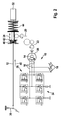
- Fig. 1 shows a schematic representation of a first embodiment of the alarm device.
- the alarm device 10 has at least one electrical conductor 16, in which caused by a Mitverstellen arranged on the driver brake power transmission component 12 magnet 14 Relative movement between the magnet 14 and the at least one electrical conductor 16, an induction voltage is inducible. This can also be described in such a way that by the Mitverstellen of the magnet 14 together with the driver brake power transmission component 12 of this relative to the at least one (fixed) electrical conductor 16 adjusted and thereby the induction voltage is induced.
- the alarm device 10 also has an output device 18, by means of which the induced induction voltage or a wake-up signal generated in consideration of the induction voltage can be output to at least one brake system component of the brake system. This can be carried out such that the at least one brake system component can be controlled by means of the induction voltage or the wake-up signal from a first energy consumption mode into a second energy consumption mode deviating from the first energy consumption mode.
- the at least one brake system component is controllable by means of the induction voltage or the wake-up signal from the first energy consumption mode with a first energy consumption in the second energy consumption mode with a second energy consumption increased compared to the first energy consumption.
- the at least one brake system component may be controllable by the induction voltage or the wake-up signal from a deactivated / dormant mode as the first energy consumption mode to an activated / fully active mode as the second energy consumption mode.
- the magnet 14 is adjustable by means of a transmission device 20 to the adjustable driver brake power transmission component 12 such that the magnet can be displaced by Mitverstellen in a rotational movement 22.
- the transmission device 20 may be designed so that by means of the transmission device 20, a linear movement 24 of the driver brake force transmission component 12 in the rotational movement 22 of the magnet 14 can be translated.
- the transmission device 20 may be, for example, a transmission. It should be understood, however, that the operability of the transmission device 20 is not limited to a particular type of transmission or gear-like device.
- a magnet 14 is used, which is connected via a linear movement-rotational movement-translation element as a transmission device 20 with the driver brake power transmission component 12.
- a magnet 14 is often connected to the driver braking force transmission component 12 in this manner.
- the magnet 14 used for the wake-up device 10 may additionally fulfill its conventionally performed function. Due to the realized multi-functionality of the magnet 14 in the wake-up device 10, a cost-effective and / or space-saving equipment of a brake system with the wake-up device can be effected.
- the magnet 14 may be a permanent magnet of an electric motor 26 of a brake booster device 28.
- a permanent magnet of an electric motor 26 such as a PSM motor
- a transmission device 20 is often connected via a transmission device 20 to a driver brake power transmission component 12 such that an additional brake assist force is exertable on the driver brake power transmission component 12 by the electric motor 26.
- the magnet 14 of the electric motor 26 is automatically translated into the rotational movement 22 when the driver brake force transmission component 12 is adjusted, at least by means of the driver braking force.
- the embodiment described here can thus be easily formed on a brake system.
- the driver brake power transmission component 12 may be, for example, an input rod.
- the magnet 14 can be arranged / arranged on the input rod by means of the transmission device 20 in such a way that the magnet 14 is set into the rotational movement 22 by the linear movement 24 of the driver brake force transmission component 12 in the form of an input rod.
- a driver brake force transmission component 12 can be understood by the input rod, via which a driver braking force exerted on a brake actuating element 30 can be transmitted to at least one adjustable piston of a master brake cylinder 32 of the brake system.
- the brake operating member 30 may be, for example, a brake pedal. It should be noted, however, that the formability of the alarm device is not limited to a magnet 14 that can be arranged on an input rod.
- the at least one electrical conductor 16 may comprise at least one drive line of the brake booster device 28.
- an already frequently used in a control electronics 34 of the brake booster 28 component for the at least one electrical conductor 16 can be used.
- another embodiment of the at least one electrical conductor 16 is also possible.
- Fig. 1 schematically reproduced embodiment thus realizes an electromechanical brake booster, in which the alarm device 10 is integrated.
- Actuation of the brake operating member 30 by the driver causes driving of the thus meshed drive comprising the input rod formed as the driver braking force transmission component 12.
- the magnet 14 connected to the drive via the transmission device 20 is set in the rotational movement 22 and induces the induction voltage as a generator in the at least one electrical conductor 16, which can also be used as a control line.
- the output device 18 can detect the induction voltage, for example, at the motor terminals as a voltage pulse and control by means of this voltage pulse as a wake-up signal at least one brake system component from the first energy consumption mode in the second energy consumption mode. This can be described in particular as an awakening of the at least one brake system component.
- the brake booster device 28 By means of the induction voltage or the wake-up signal, for example, the brake booster device 28, an ABS device, an ESP device, a plunger device, an electric power steering, a CAN network and / or a boost network as the at least one brake system component from the deactivated mode in the activated mode be controllable.
- a further brake system component can also be controlled / awakened by means of the signal output by the output device 18.
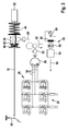
- Fig. 2 shows a schematic representation of a second embodiment of the alarm clock.
- Fig. 2 is designed as a permanent magnet of the electric motor 26 of the brake booster 28 formed magnet 14 of the alarm 10 on an input rod formed as adjustable driver brake power transmission component 12 that the magnet 14 of the alarm 10 by means of the transmission device 20 with the driver brake power transmission component 12 is mitver mod. It is ensured that the magnet 14 is displaceable by the Mitverstellen with the adjustable driver brake power transmission component 12 in the rotational movement 22. In this way, a braking system of at least the alarm device 10 and the adjustable driver brake power transmission component 12 feasible, in which the advantages already mentioned above are guaranteed.
- the advantages already described above also in the training of the Fig. 2 can be effected, although the drive with the formed as an input rod driver brake power transmission component 12 can only assist in a Einbremscardi 40 as the actuation direction.
- the advantageous technology is also applicable to a brake system whose input rod between the brake actuator 30 and the master cylinder 32 is guided coaxially or non-coaxially through a mitver mone sleeve 42.
- An elastic stop 46 is formed on a side of the sleeve 42 directed away from the return spring 44.
- the engaging with the drive sleeve 42 is moved in the Einbremscardi 40.
- This movement of the sleeve 42 in the Einbremscardi 40 causes the rotational movement 22 of the magnet 14, whereby the induction voltage in the at least one conductor 16 is induced, which is detectable / detectable as a generator voltage pulse at the motor terminals.
- the voltage pulse can be used as a wake-up signal for activating at least one brake system component.
- Fig. 3 shows a schematic representation of a third embodiment of the alarm device.
- a magnet 50 of a sensor for generating / inducing the induction voltage / the wake-up signal is used.
- the magnet 50 may be a permanent magnet / permanent magnet.
- the magnet 50 may be a permanent magnet of a rotor position sensor 54.
- the rotor position sensor 54 is preferably a non-contact sensor with a permanent magnet used as the magnet 50.
- the usability of a magnet 50 for the alarm device 48 is not limited to the examples mentioned here.
- the magnet 50 is adjustably arranged / arranged on the adjustable driver brake force transmission component 12 by means of the transmission device 20 in such a way that the magnet 50 can be displaced into the rotational movement 52 by the co-adjustment with the linearly moved driver brake force transmission component 12.
- the electrical conductor 56 in which the induction voltage can be induced by means of the magnet 50 offset in the rotational movement 52, comprises at least one stationary coil 56 of the rotor position sensor 54.
- the output device 58 is an electronics unit electrically connected to the at least one coil 56. Even if an additional coil is to be arranged on the rotor position sensor 54 for the electrical conductor 56, this can be carried out comparatively cheaply.
- the advantageous wake-up device 48 can thus also be integrated into a rotor position sensor 54. Also in this case, the advantages already mentioned above are reliably realizable.
- the rotor position sensor 54 may be a subunit of the brake booster device 28.
- a brake booster device 28 having an (electrically commutated) motor 26 often includes a rotor position sensor 54 which signals electronics to detect the position of a rotor of the motor 26 for commutation.
- sensors can be used for integration of the wake-up device 48 often already existing on the brake booster device 28 sensors.
- the rotor position sensor 54 can be used both as a wake-up device 48 and as a sensor for determining and outputting an information 60 with respect to a position of the rotor of the motor 26.
- Fig. 4 shows a flowchart for illustrating an embodiment of the method for awakening at least one brake system component of a vehicle.
- a magnet arranged in an adjustable manner on an adjustable driver brake power transmission component of a brake system of the vehicle is provided.
- the provision of the magnet is carried out so that the magnet used by means of a transmission device on the (preferably linear) adjustable driver brake power transmission component is arranged to be adjustable, that the magnet is offset by the Mitverstellen in a rotational movement.
- At least one electrical conductor is provided in a simultaneously, previously or subsequently executable method step S2.
- the electrical conductor is provided in such a way that, in the case of a relative movement between the magnet and the electrical conductor caused by the co-displacement of the magnet arranged on the driver brake force transmission component, an induction voltage is induced in the at least one electrical conductor.
- the induced induction voltage or a wake-up signal generated taking into account the induction voltage is output to the at least one brake system component of the brake system in such a way that the at least one brake system component changes from a first energy consumption mode to one of the first energy consumption mode by means of the induction voltage or wake-up signal Energy consumption mode is controlled deviating second energy consumption mode.
- the induction current or the wake-up signal may be provided to a processor or circuit of the at least one brake system component.
- the induction voltage can also be converted into the wake-up signal.
- the advantageous method described above allows the use of a magnet of an electric motor or a sensor for the alarm.
- a magnet of an electric motor of a brake booster device and / or a permanent magnet of a rotor position sensor of the brake booster device may be used.
Landscapes
- Engineering & Computer Science (AREA)
- Transportation (AREA)
- Mechanical Engineering (AREA)
- Braking Systems And Boosters (AREA)
- Braking Arrangements (AREA)
- Valves And Accessory Devices For Braking Systems (AREA)
- Power Engineering (AREA)
- Toys (AREA)
- Physics & Mathematics (AREA)
- Electromagnetism (AREA)
- Regulating Braking Force (AREA)
Description
- Die Erfindung betrifft eine Weckvorrichtung für eine Bremssystemkomponente eines Fahrzeugs. Des Weiteren betrifft die Erfindung ein Verfahren zum Wecken mindestens einer Bremssystemkomponente eines Fahrzeugs.
- In der
DE 101 23 730 A1 sind ein System, ein Positionsgeber und eine Empfangseinrichtung zur sicheren Übertragung der Position eines Betätigungselements beschrieben. Das System weist eine Weckeinrichtung auf, welche dazu ausgelegt ist, in einem Sensorkanal ein zum Wecken zulässiges Signal zu erkennen und anschließend weitere Komponenten von einem schlafenden Modus in einen vollaktivierten Betriebsmodus zu steuern. Das zum Wecken zulässige Signal wird über mindestens einen linear an einem Pedal mitverstellbar angeordneten Magneten in den Sensorkanal induziert. - Die Erfindung schafft eine Weckvorrichtung für eine Bremssystemkomponente eines Fahrzeugs mit den Merkmalen des Anspruchs 1, eine Bremskraftverstärkervorrichtung für ein Bremssystem eines Fahrzeugs mit den Merkmalen des Anspruchs 9, ein Bremsgerät für ein Bremssystem eines Fahrzeugs mit den Merkmalen des Anspruchs 10 und ein Verfahren zum Wecken mindestens einer Bremssystemkomponente eines Fahrzeugs mit den Merkmalen des Anspruchs 12.
- Die vorliegende Erfindung ermöglicht es, zum Induzieren einer zum Wecken mindestens einer Bremssystemkomponente verwendbaren Induktionsspannung, bzw. eines korrespondierenden Induktionsstroms, einen Magneten zu verwenden, welcher mittels einer Getriebeeinrichtung derart an der verstellbaren Fahrerbremskraftübertragungskomponente mitverstellbar anordbar/angeordnet ist, dass der Magnet durch das Mitverstellen mit der Fahrerbremskraftübertragungskomponente in eine Rotationsbewegung versetzbar ist. Somit können zum Induzieren der Induktionsspannung auch Magneten herangezogen werden, welche in der Regel bereits mittels einer Getriebeeinrichtung mit einer Fahrerbremskraftübertragungskomponente mitverstellbar angeordnet sind. Die vorliegende Erfindung realisiert somit die Ausbildung einer Weckvorrichtung, welche als Magneten einen bereits herkömmlicher Weise für eine andere Funktion genutzten Magneten verwenden kann. Durch die auf diese Weise realisierbare Multifunktionalität des Magneten kann auf einen ausschließlich für die Weckvorrichtung verwendeten Magneten verzichtet werden. Dies bewirkt eine Einsparung von Bauraum und eine Reduzierung von Kosten für ein Ausstatten eines Fahrzeugs mit einem eine Weckfunktion ausführenden Bremssystem.
- Die vorliegende Erfindung ermöglicht auch das Ausbilden einer Weckfunktion an einem Bremssystem ohne einen Bremslichtschalter. Häufig wird der Bremslichtschalter bei einem Bremssystem mit einem elektromechanischen Bremskraftverstärker eingespart Somit kann der eingesparte Bremslichtschalter in diesem Fall nicht zum Aktivieren des vorliegenden Bremssystems verwendet werden. Mittels der vorliegenden Erfindung kann jedoch auch in diesem Fall die Induktionsspannung oder das Wecksignal an die mindestens eine Bremssystemkomponente zum Wecken bereitgestellt werden. Auch der elektromechanische Bremskraftverstärker kann so geweckt werden. Dies ist auch gewährleistet, sofern alle internen Sensoren in einem deaktivierten Modus/passiv vorliegen und nicht zum Erzeugen eines Aktivierungssignals/Wecksignals ausgelegt sind.
- Die vorliegende Erfindung ermöglicht ein Einschalten/Wecken mindestens einer Bremssystemkomponente, wie beispielsweise eines Bremskraftverstärkers, durch ein bei einem Betätigen einer Bremsbetätigungskomponente, wie einem Bremspedal, generiertes Induktionssignal/Wecksignal. Somit ist die zuvor in einem passiven Zustand vorliegende mindestens eine Bremssystemkomponente durch eine Betätigung der Bremssystemkomponente auf einfache Weise und verlässlich in einen aktiven Zustand überführbar. Insbesondere ist durch die hier aufgeführte Erfindung ein Einschalten/Wecken der mindestens einen Bremssystemkomponente durch ein internes, induktiv generiertes Signal möglich, ohne dass dazu einer der internen Sensoren aktiv vorliegen muss und somit Strom verbraucht.
- Die Bremssystemkomponente weist in dem ersten Energieverbrauch-Modus einen ersten Energieverbrauch auf, welcher von einem zweiten Energieverbrauch der Bremssystemkomponente in dem zweiten Energieverbrauch-Modus abweicht. Beispielsweise kann in dem ersten Energieverbrauch-Modus eine andere Anzahl von Untereinheiten der Bremssystemkomponente aktiviert sein als in dem zweiten Energieverbrauch-Modus. Unter dem ersten Energieverbrauch oder dem zweiten Energieverbrauch kann die zeitlich gemittelte verbrauchte Energie der in den ersten Energieverbrauch-Modus oder in den zweiten Energieverbrauch-Modus gesteuerten Bremssystemkomponente verstanden werden.
- Vorteilhaftverweise ist die mindestens eine Bremssystemkomponente mittels der Induktionsspannung oder des Wecksignals aus dem ersten Energieverbrauch-Modus mit einem ersten Energieverbrauch in den zweiten Energieverbrauch-Modus mit einem gegenüber dem ersten Energieverbrauch gesteigerten zweiten Energieverbrauch steuerbar. Insbesondere kann die mindestens eine Bremssystemkomponente mittels der Induktionsspannung oder des Wecksignals aus einem deaktivierten/schlafenden Modus als dem ersten Energieverbrauch-Modus in einen aktivierten/vollaktiven Modus als den zweiten Energieverbrauch-Modus steuerbar sein.
- In einer vorteilhaften Ausführungsform kann der Magnet ein Permanentmagnet eines Elektromotors einer Bremskraftverstärkervorrichtung und/oder ein Permanentmagnet eines Rotor-Lagesensors sein. Man kann dies auch so umschreiben, dass durch das Betätigen des Bremsbetätigungselements der Elektromotor oder der Rotor-Lagesensor als Generator nutzbar ist, um einen dabei erzeugten Spannungsimpuls als Aktivierungsimpuls zum Einschalten der mindestens einen Bremssystemkomponente zu verwenden.
- Beispielsweise kann der Magnet mittels der Getriebeeinrichtung an einer Eingangsstange, über welche eine auf das Bremsbetätigungselement ausgeübte Fahrerbremskraft auf mindestens einen verstellbaren Kolben eines Hauptbremszylinders übertragbar ist, als der mitverstellbaren Fahrerbremskraftübertragungskomponente mitverstellbar anordbar sein. Somit kann für den Magneten ein herkömmlicher Weise häufig bereits über eine Getriebeeinrichtung mit der Eingangsstange verbundener Magnet genutzt werden. Dies bewirkt ein Einsparen eines nach dem Stand der Technik lediglich als Weckgerät genutzten Magneten.
- In einer weiteren vorteilhaften Ausführungsform können mittels der Induktionsspannung oder des Wecksignals die Bremskraftverstärkervorrichtung, eine ABS-Vorrichtung, eine ESP-Vorrichtung, eine Plungervorrichtung, eine elektrische Servolenkung, ein CAN-Netzwerk und/oder ein Boost-Netzwerk als die mindestens eine Bremssystemkomponente aus dem ersten Energieverbrauch-Modus in den zweiten Energieverbrauch-Modus steuerbar sein. Somit kann die erfindungsgemäße Weckvorrichtung für eine Vielzahl von Bremssystemkomponenten genutzt werden.
- In einer kostengünstigen Ausführungsform umfasst der elektrische Leiter mindestens eine Ansteuerleitung der Bremskraftverstärkervorrichtung. Ebenso kann der elektrische Leiter mindestens eine ortsfeste Spule des Rotor-Lagesensors umfassen. Für den elektrischen Leiter können somit herkömmlicher Weise bereits in einem Bremssystem vorhandene Komponenten genutzt werden.
- Die in den vorausgehenden Absätzen beschriebenen Vorteile sind auch bei einer Bremskraftverstärkervorrichtung mit einer entsprechenden Weckvorrichtung gewährleistet.
- Außerdem sind die genannten Vorteile bei einem Bremsgerät mit einer derartigen Weckvorrichtung und einer verstellbaren Fahrerbremskraftübertragungskomponente, an welcher der Magnet der Weckvorrichtung mittels der Getriebeeinrichtung derart mitverstellbar angeordnet ist, dass der Magnet durch das Mitverstellen mit der verstellbaren Fahrerbremskraftübertragungskomponente in eine Rotationsbewegung versetzbar ist, realisiert.
- Zusätzlich können die Vorteile mittels eines Bremssystems mit einer derartigen Weckvorrichtung, einer korrespondierenden Bremskraftverstärkervorrichtung oder einem entsprechend ausgebildeten Bremsgerät realisiert werden.
- Des Weiteren bewirkt auch ein korrespondierendes Verfahren zum Wecken mindestens einer Bremssystemkomponente eines Fahrzeugs die oben beschriebenen Vorteile.
- Weitere Merkmale und Vorteile der vorliegenden Erfindung werden nachfolgend anhand der Figuren erläutert. Es zeigen:
- Fig. 1
- eine schematische Darstellung einer ersten Ausführungsform der Weckvorrichtung;
- Fig. 2
- eine schematische Darstellung einer zweiten Ausführungsform der Weckvorrichtung;
- Fig. 3
- eine schematische Darstellung einer dritten Ausführungsform der Weckvorrichtung; und
- Fig. 4
- ein Flussdiagramm zum Darstellen einer Ausführungsform des Verfahrens zum Wecken mindestens einer Bremssystemkomponente eines Fahrzeugs.
-
Fig. 1 zeigt eine schematische Darstellung einer ersten Ausführungsform der Weckvorrichtung. - Die in
Fig. 1 schematisch dargestellte Weckvorrichtung 10 umfasst einen an einer verstellbaren Fahrerbremskraftübertragungskomponente 12 eines Bremssystems des Fahrzeugs mitverstellbar anordbaren/angeordneten Magneten 14. Zusätzlich weist die Weckvorrichtung 10 mindestens einen elektrischen Leiter 16 auf, in welchem bei einer durch das Mitverstellen des an der Fahrerbremskraftübertragungskomponente 12 angeordneten Magneten 14 bewirkten Relativbewegung zwischen dem Magneten 14 und den mindestens einen elektrischen Leiter 16 eine Induktionsspannung induzierbar ist. Man kann dies auch so umschreiben, dass durch das Mitverstellen des Magneten 14 zusammen mit der Fahrerbremskraftübertragungskomponente 12 dieser gegenüber dem mindestens einen (ortsfesten) elektrischen Leiter 16 verstellt und dadurch die Induktionsspannung induziert wird. - Die Weckvorrichtung 10 hat auch eine Ausgabeeinrichtung 18, mittels welcher die induzierte Induktionsspannung oder ein unter Berücksichtigung der Induktionsspannung erzeugtes Wecksignal an mindestens eine Bremssystemkomponente des Bremssystems ausgebbar ist. Dies ist so ausführbar, dass die mindestens eine Bremssystemkomponente mittels der Induktionsspannung oder des Wecksignals aus einem ersten Energieverbrauch-Modus in einen von dem ersten Energieverbrauch-Modus abweichenden zweiten Energieverbrauch-Modus steuerbar ist.
- Vorteilhaftverweise ist die mindestens eine Bremssystemkomponente mittels der Induktionsspannung oder des Wecksignals aus dem ersten Energieverbrauch-Modus mit einem ersten Energieverbrauch in den zweiten Energieverbrauch-Modus mit einem gegenüber dem ersten Energieverbrauch gesteigerten zweiten Energieverbrauch steuerbar. Insbesondere kann die mindestens eine Bremssystemkomponente mittels der Induktionsspannung oder des Wecksignals aus einem deaktivierten/schlafenden Modus als dem ersten Energieverbrauch-Modus in einen aktivierten/vollaktiven Modus als den zweiten Energieverbrauch-Modus steuerbar sein.
- Der Magnet 14 ist mittels einer Getriebeeinrichtung 20 derart an der verstellbaren Fahrerbremskraftübertragungskomponente 12 mitverstellbar anordbar, dass der Magnet durch das Mitverstellen in eine Rotationsbewegung 22 versetzbar ist. Insbesondere kann die Getriebeeinrichtung 20 so ausgelegt sein, dass mittels der Getriebeeinrichtung 20 eine Linearbewegung 24 der Fahrerbremskraftübertragungskomponente 12 in die Rotationsbewegung 22 des Magneten 14 übersetzbar ist. Die Getriebeeinrichtung 20 kann beispielsweise ein Getriebe sein. Es wird jedoch darauf hingewiesen, dass die Ausführbarkeit der Getriebeeinrichtung 20 nicht auf einen bestimmten Typ eines Getriebes oder einer getriebeähnlichen Einrichtung limitiert ist.
- Für die Weckvorrichtung 10 ist somit ein Magnet 14 verwendbar, welcher über ein Linearbewegung-Rotationsbewegung-Übersetzungselement als Getriebeeinrichtung 20 mit der Fahrerbremskraftübertragungskomponente 12 verbunden ist. Herkömmlicherweise ist häufig mindestens ein Magnet 14 auf diese Weise mit der Fahrerbremskraftübertragungskomponente 12 verbunden. Somit kann ein bereits in einem Bremssystem vorhandener/genutzter Magnet 14 zum Realisieren der Weckvorrichtung 10 genutzt werden. Der für die Weckvorrichtung 10 genutzte Magnet 14 kann zusätzlich noch seine herkömmlicher Weise ausgeführte Funktion erfüllen. Durch die realisierte Multifunktionalität des Magneten 14 bei der Weckvorrichtung 10 ist eine kostengünstige und/oder bauraumsparende Ausstattung eines Bremssystems mit der Weckvorrichtung bewirkbar.
- Beispielsweise kann der Magnet 14 ein Permanentmagnet eines Elektromotors 26 einer Bremskraftverstärkervorrichtung 28 sein. Herkömmlicherweise ist oft ein Permanentmagnet eines Elektromotors 26, wie beispielsweise eines PSM-Motors, über eine Getriebeeinrichtung 20 so mit einer Fahrerbremskraftübertragungskomponente 12 verbunden, dass eine zusätzliche Bremsunterstützungskraft mittels des Elektromotors 26 auf die Fahrerbremskraftübertragungskomponente 12 ausübbar ist. Gleichzeitig ist in der Regel gewährleistet, dass der Magnet 14 des Elektromotors 26 bei einem Verstellen der Fahrerbremskraftübertragungskomponente 12 zumindest mittels der Fahrerbremskraft automatisch in die Rotationsbewegung 22 mitversetzt wird. Die hier beschriebene Ausführungsform ist somit auf einfache Weise an einem Bremssystem ausbildbar.
- Die Fahrerbremskraftübertragungskomponente 12 kann beispielsweise eine Eingangsstange sein. In diesem Fall ist der Magnet 14 mittels der Getriebeeinrichtung 20 so an der Eingangsstange anordbar/angeordnet, dass der Magnet 14 durch die Linearbewegung 24 der als Eingangsstange ausgebildeten Fahrerbremskraftübertragungskomponente 12 in die Rotationsbewegung 22 versetzt wird. Unter der Eingangsstange kann dabei eine Fahrerbremskraftübertragungskomponente 12 verstanden werden, über welche eine auf ein Bremsbetätigungselement 30 ausgeübte Fahrerbremskraft auf mindestens einen verstellbaren Kolben eines Hauptbremszylinders 32 des Bremssystems übertragbar ist. Das Bremsbetätigungselement 30 kann beispielsweise ein Bremspedal sein. Es wird jedoch darauf hingewiesen, dass die Ausbildbarkeit der Weckvorrichtung nicht auf einen an einer Eingangsstange anordbaren Magneten 14 beschränkt ist.
- Der mindestens eine elektrische Leiter 16 kann mindestens eine Ansteuerleitung der Bremskraftverstärkervorrichtung 28 umfassen. Somit kann eine bereits häufig in einer Steuerelektronik 34 der Bremskraftverstärkervorrichtung 28 vorhandene Komponente für den mindestens einen elektrischen Leiter 16 genutzt werden. Eine andere Ausbildung des mindestens einen elektrischen Leiters 16 ist jedoch ebenso möglich.
- Die in
Fig. 1 schematisch wiedergegebene Ausführungsform realisiert somit einen elektromechanischen Bremskraftverstärker, in welchem die Weckvorrichtung 10 integriert ist. Eine Betätigung des Bremsbetätigungselements 30 durch den Fahrer bewirkt ein Antreiben des damit in einem Eingriff stehenden Antriebs umfassend die als Fahrerbremskraftübertragungskomponente 12 ausgebildete Eingangsstange. Der über die Getriebeeinrichtung 20 mit dem Antrieb verbundene Magnet 14 wird in die Rotationsbewegung 22 versetzt und induziert als Generator in dem mindestens einen auch als Ansteuerleitung nutzbaren elektrischen Leiter 16 die Induktionsspannung. Die Ausgabeeinrichtung 18 kann die Induktionsspannung beispielsweise an den Motorklemmen als Spannungsimpuls detektieren und mittels dieses Spannungsimpuls als Wecksignal mindestens eine Bremssystemkomponente aus dem ersten Energieverbrauch-Modus in den zweiten Energieverbrauch-Modus steuern. Man kann dies insbesondere als ein Wecken der mindestens einen Bremssystemkomponente umschreiben. - Mittels der Induktionsspannung oder des Wecksignals können beispielsweise die Bremskraftverstärkervorrichtung 28, eine ABS-Vorrichtung, eine ESP-Vorrichtung, eine Plungervorrichtung, eine elektrische Servolenkung, ein CAN-Netzwerk und/oder ein Boost-Netzwerk als die mindestens eine Bremssystemkomponente aus dem deaktivierten Modus in den aktivierten Modus steuerbar sein. Zusätzlich zu den hier aufgezählten Bremssystemkomponenten kann auch eine weitere Bremssystemkomponente mittels des von der Ausgabeeinrichtung 18 ausgegebenen Signals steuerbar/weckbar sein.
-
Fig. 2 zeigt eine schematische Darstellung einer zweiten Ausführungsform der Weckvorrichtung. - In der Ausführungsform der
Fig. 2 ist der als Permanentmagnet des Elektromotors 26 der Bremskraftverstärkervorrichtung 28 ausgebildete Magnet 14 der Weckvorrichtung 10 so an einer als Eingangsstange ausgebildeten verstellbaren Fahrerbremskraftübertragungskomponente 12 angeordnet, dass der Magnet 14 der Weckvorrichtung 10 mittels der Getriebeeinrichtung 20 mit der Fahrerbremskraftübertragungskomponente 12 mitverstellbar ist. Dabei ist gewährleistet, dass der Magnet 14 durch das Mitverstellen mit der verstellbaren Fahrerbremskraftübertragungskomponente 12 in die Rotationsbewegung 22 versetzbar ist. Auf diese Weise ist ein Bremssystem aus zumindest der Weckvorrichtung 10 und der verstellbaren Fahrerbremskraftübertragungskomponente 12 realisierbar, bei welchem die oben schon genannten Vorteile gewährleistet sind. - Es wird darauf hingewiesen, dass die oben schon beschriebenen Vorteile auch bei der Ausbildungsform der
Fig. 2 bewirkbar sind, obwohl der Antrieb mit der als Eingangsstange ausgebildeten Fahrerbremskraftübertragungskomponente 12 nur in eine Einbremsrichtung 40 als Betätigungsrichtung unterstützend wirken kann. Somit ist die vorteilhafte Technologie auch anwendbar auf ein Bremssystem, dessen Eingangsstange zwischen dem Bremsbetätigungselement 30 und dem Hauptbremszylinder 32 koaxial oder nicht-koaxial durch eine mitverstellbare Hülse 42 geführt ist. Ein Verschieben der Eingangsstange in die Einbremsrichtung 40, d.h. von dem Bremsbetätigungselement 30 zu dem Hauptbremszylinder 32, bewirkt eine Verstellbewegung der mitverstellbaren Hülse 42 auf den Hauptbremszylinder 32 zu, wodurch eine an einer zu dem Hauptbremszylinder 32 gerichteten Seite der Hülse angeordnete Rückstellfeder 44 komprimiert wird. (Mittels der Rückstellfeder 44 kann das Bremsbetätigungselement 32 nach einer Betätigung durch einen Fahrer wieder in eine Ausgangsstellung zurückversetzt werden.) - Ein elastischer Anschlag 46 ist an einer von der Rückstellfeder 44 weggerichteten Seite der Hülse 42 ausgebildet. Eine Betätigung des Bremsbetätigungselements 30 durch den Fahrer, bei welcher die Rückstellfeder 44 komprimiert wird, betätigt den Hauptbremszylinder 32 und entspannt den elastischen Anschlag 46. Dabei wird die mit dem Antrieb in Eingriff stehende Hülse 42 in die Einbremsrichtung 40 bewegt. Diese Bewegung der Hülse 42 in die Einbremsrichtung 40 bewirkt die Rotationsbewegung 22 des Magneten 14, wodurch die Induktionsspannung in dem mindestens einen Leiter 16 induziert wird, welche als generatorischer Spannungsimpuls an den Motorklemmen ermittelbar/nachweisbar ist. Anschließend kann der Spannungsimpuls als Wecksignal zum Aktivieren mindestens einer Bremssystemkomponente verwendet werden. Somit ist selbst bei einer inaktivierten Bremskraftverstärkervorrichtung 28 durch den generatorischen Betrieb des Magneten 14, welcher im Eingriff mit dem Antrieb steht, das Wecksignal verlässlich erzeugbar.
-
Fig. 3 zeigt eine schematische Darstellung einer dritten Ausführungsform der Weckvorrichtung. - Bei der in
Fig. 3 schematisch dargestellten Weckvorrichtung 48 wird ein Magnet 50 eines Sensors zur Erzeugung/Induzierung der Induktionsspannung/des Wecksignals genutzt. Der Magnet 50 kann ein Permanentmagnet/Dauermagnet sein. Insbesondere kann der Magnet 50 ein Permanentmagnet eines Rotor-Lagesensors 54 sein. Der Rotor-Lagesensor 54 ist vorzugsweise ein berührungsloser Sensor mit einem als Magnet 50 genutzten Dauermagneten. Die Verwendbarkeit eines Magneten 50 für die Weckvorrichtung 48 ist jedoch nicht auf die hier genannten Beispiele limitiert. - Der Magnet 50 ist mittels der Getriebeeinrichtung 20 so an der verstellbaren Fahrerbremskraftübertragungskomponente 12 mitverstellbar anordbar/angeordnet, dass der Magnet 50 durch das Mitverstellen mit der linear bewegten Fahrerbremskraftübertragungskomponente 12 in die Rotationsbewegung 52 versetzbar ist. Der elektrische Leiter 56, in welchem mittels des in die Rotationsbewegung 52 versetzten Magneten 50 die Induktionsspannung induzierbar ist, umfasst mindestens eine ortsfeste Spule 56 des Rotor-Lagesensors 54. Die Ausgabeeinrichtung 58 ist eine mit der mindestens einen Spule 56 elektrisch verbundene Elektronik. Selbst wenn für den elektrischen Leiter 56 eine zusätzlich Spule an dem Rotor-Lagesensor 54 anzuordnen ist, so ist dies vergleichsweise billig ausführbar.
- Die vorteilhafte Weckvorrichtung 48 ist somit auch in einen Rotor-Lagesensor 54 integrierbar. Auch in diesem Fall sind die oben schon genannten Vorteile verlässlich realisierbar.
- Der Rotor-Lagesensor 54 kann eine Untereinheit der Bremskraftverstärkervorrichtung 28 sein. Insbesondere eine Bremskraftverstärkervorrichtung 28 mit einem (elektrisch kommutierten) Motor 26 umfasst häufig einen Rotor-Lagesensor 54, welcher einer Elektronik die Lage eines Rotors des Motors 26 für eine Kommutierung meldet. Somit kann zur Integration der Weckvorrichtung 48 eine oft bereits an der Bremskraftverstärkervorrichtung 28 vorhandene Sensorik genutzt werden. In diesem Fall kann der Rotor-Lagesensor 54 sowohl als Weckvorrichtung 48 als auch als Sensor zum Ermitteln und Ausgeben einer Information 60 bezüglich einer Stellung des Rotors des Motors 26 genutzt werden. Durch diese Multifunktionalität des Rotor-Lagesensors 54 können Herstellungskosten eingespart und ein Bauraumbedarf der Weckvorrichtung 48 limitiert werden.
-
Fig. 4 zeigt ein Flussdiagramm zum Darstellen einer Ausführungsform des Verfahrens zum Wecken mindestens einer Bremssystemkomponente eines Fahrzeugs. - In einem Verfahrensschritt S1 wird ein an einer verstellbaren Fahrerbremskraftübertragungskomponente eines Bremssystems des Fahrzeugs mitverstellbar angeordneter Magnet bereitgestellt. Das Bereitstellen des Magneten erfolgt so, dass der benutzte Magnet mittels einer Getriebeeinrichtung derart an der (vorzugsweise linear) verstellbaren Fahrerbremskraftübertragungskomponente mitverstellbar angeordnet ist, dass der Magnet durch das Mitverstellen in eine Rotationsbewegung versetzt wird.
- In einem gleichzeitig, zuvor oder nachfolgend ausführbaren Verfahrensschritt S2 wird mindestens ein elektrischer Leiter bereitgestellt. Das Bereitstellen des elektrischen Leiters erfolgt so, dass bei einer durch das Mitverstellen des an der Fahrerbremskraftübertragungskomponente angeordneten Magneten bewirkten Relativbewegung zwischen dem Magneten und dem elektrischen Leiter eine Induktionsspannung in dem mindestens einen elektrischen Leiter induziert wird.
- Des Weiteren wird in einem Verfahrensschritt S3 die induzierte Induktionsspannung oder ein unter Berücksichtigung der Induktionsspannung erzeugtes Wecksignal so an die mindestens eines Bremssystemkomponente des Bremssystems ausgegeben, dass die mindestens eine Bremssystemkomponente mittels der Induktionsspannung oder des Wecksignals aus einem ersten Energieverbrauch-Modus in einen von dem ersten Energieverbrauch-Modus abweichenden zweiten Energieverbrauch-Modus gesteuert wird. Beispielsweise kann der Induktionsstrom oder das Wecksignal an einen Prozessor oder einen Schaltkreis der mindestens einen Bremssystemkomponente bereitgestellt werden. Zum Erzeugen des Wecksignals kann auch die Induktionsspannung in das Wecksignal umgewandelt werden.
- Das oben beschriebene vorteilhafte Verfahren ermöglicht die Verwendung eines Magneten eines Elektromotors oder eines Sensors für die Weckvorrichtung. Beispielsweise kann als Magnet ein Permanentmagnet eines Elektromotors einer Bremskraftverstärkervorrichtung und/oder ein Permanentmagnet eines Rotor-Lagesensors der Bremskraftverstärkervorrichtung verwendet werden.
Claims (13)
- Weckvorrichtung (10, 48) für eine Bremssystemkomponente (28) eines Fahrzeugs mit:einem an einer verstellbaren Fahrerbremskraftübertragungskomponente (12) eines Bremssystems mitverstellbar anordbaren Magneten (14, 50);einem elektrischen Leiter (16, 56), in welchem bei einer durch ein Mitverstellen des an der Fahrerbremskraftübertragungskomponente (12) angeordneten Magneten (14, 50) bewirkten Relativbewegung zwischen dem Magneten (14, 50) und dem elektrischen Leiter (16, 56) eine Induktionsspannung induzierbar ist; undeiner Ausgabeeinrichtung (18, 58), mittels welcher die induzierte Induktionsspannung oder ein unter Berücksichtigung der Induktionsspannung erzeugtes Wecksignal an die mindestens eine Bremssystemkomponente (28) so ausgebbar ist, dass die mindestens eine Bremssystemkomponente (28) mittels der Induktionsspannung oder des Wecksignals aus einem ersten Energieverbrauch-Modus in einen von dem ersten Energieverbrauch-Modus abweichenden zweiten Energieverbrauch-Modus steuerbar ist;dadurch gekennzeichnet, dassder Magnet (14, 50) mittels einer Getriebeeinrichtung (20) derart an der verstellbaren Fahrerbremskraftübertragungskomponente (12) mitverstellbar anordbar ist, dass der Magnet (14, 50) durch das Mitverstellen in eine Rotationsbewegung (22, 52) versetzbar ist.
- Weckvorrichtung (10, 48) nach Anspruch 1, wobei die mindestens eine Bremssystemkomponente (28) mittels der Induktionsspannung oder des Wecksignals aus dem ersten Energieverbrauch-Modus mit einem ersten Energieverbrauch in den zweiten Energieverbrauch-Modus mit einem gegenüber dem ersten Energieverbrauch gesteigerten zweiten Energieverbrauch steuerbar ist.
- Weckvorrichtung (10, 48) nach Anspruch 2, wobei die mindestens eine Bremssystemkomponente (28) mittels der Induktionsspannung oder des Wecksignals aus einem deaktivierten Modus als dem ersten Energieverbrauch-Modus in einen aktivierten Modus als den zweiten Energieverbrauch-Modus steuerbar ist.
- Weckvorrichtung (10, 48) nach einem der vorhergehenden Ansprüche, wobei der Magnet (14, 50) ein Permanentmagnet (14) eines Elektromotors (26) einer Bremskraftverstärkervorrichtung (28) und/oder ein Permanentmagnet (50) eines Rotor-Lagesensors (54) ist.
- Weckvorrichtung (10, 48) nach einem der vorhergehenden Ansprüche, wobei der Magnet (14, 50) mittels der Getriebeeinrichtung (20) an einer Eingangsstange, über welche eine auf ein Bremsbetätigungselement (30) ausgeübte Fahrerbremskraft auf mindestens einen verstellbaren Kolben eines Hauptbremszylinders (32) übertragbar ist, als der verstellbaren Fahrerbremskraftübertragungskomponente (12) mitverstellbar anordbar ist.
- Weckvorrichtung (10, 48) nach einem der vorhergehenden Ansprüche, wobei mittels der Induktionsspannung oder des Wecksignals die Bremskraftverstärkervorrichtung (28), eine ABS-Vorrichtung, eine ESP-Vorrichtung, eine Plungervorrichtung, eine elektrische Servolenkung, ein CAN-Netzwerk und/oder ein Boost-Netzwerk als die mindestens eine Bremssystemkomponente aus dem ersten Energieverbrauch-Modus in den zweiten Energieverbrauch-Modus steuerbar sind.
- Weckvorrichtung (10, 48) nach einem der vorhergehenden Ansprüche, wobei der elektrische Leiter (16) mindestens eine Ansteuerleitung (16) der Bremskraftverstärkervorrichtung (28) umfasst.
- Weckvorrichtung (10, 48) nach einem der Ansprüche 1 bis 6, wobei der elektrische Leiter (56) mindestens eine ortsfeste Spule (56) des Rotor-Lagesensors (54) umfasst.
- Bremskraftverstärkervorrichtung (28) für ein Bremssystem eines Fahrzeugs mit:einer Weckvorrichtung (10, 48) nach einem der vorhergehenden Ansprüche.
- Bremsgerät für ein Bremssystem eines Fahrzeugs mit:einer Weckvorrichtung (10, 48) nach einem der Ansprüche 1 bis 8; undeiner verstellbaren Fahrerbremskraftübertragungskomponente (12), an welcher der Magnet (14, 50) der Weckvorrichtung (10, 48) mittels der Getriebeeinrichtung (20) derart mitverstellbar angeordnet ist, dass der Magnet (14, 50) durch das Mitverstellen mit der verstellbaren Fahrerbremskraftübertragungskomponente (12) in eine Rotationsbewegung (22, 52) versetzbar ist.
- Bremssystem für ein Fahrzeug mit einer Weckvorrichtung (10, 48) nach einem der Ansprüche 1 bis 8, einer Bremskraftverstärkervorrichtung (28) nach Anspruch 9 oder einem Bremsgerät nach Anspruch 10.
- Verfahren zum Wecken mindestens einer Bremssystemkomponente (28) eines Fahrzeugs mit den Schritten:Bereitstellen eines an einer verstellbaren Fahrerbremskraftübertragungskomponente (12) mitverstellbar angeordneten Magneten (14, 50);Bereitstellen eines elektrischen Leiters (16, 56), im welchen bei einer durch ein Mitverstellen des an der Fahrerbremskraftübertragungskomponente (12) angeordneten Magneten (14, 50) bewirkten Relativbewegung zwischen dem Magneten (14, 50) und dem elektrischen Leiter (16, 56) eine Induktionsspannung induziert wird (S2); undAusgeben der Induktionsspannung oder eines unter Berücksichtigung der Induktionsspannung erzeugten Wecksignals so an die mindestens eine Bremssystemkomponente (28), dass die mindestens eine Bremssystemkomponente (28) mittels der Induktionsspannung oder des Wecksignals aus einem ersten Energieverbrauch-Modus in einen von dem ersten Energieverbrauch-Modus abweichenden zweiten Energieverbrauch-Modus gesteuert wird (S3);gekennzeichnet durch den Schritt:Mitverstellbares Anordnen des Magneten (14, 50) mittels einer Getriebeeinrichtung (20) derart an der verstellbaren Fahrerbremskraftübertragungskomponente (12), dass der Magnet (14, 50) durch das Mitverstellen in eine Rotationsbewegung (22, 52) versetzt wird, beim Bereitstellen des Magneten (14, 50) (S1).
- Verfahren nach Anspruch 12, wobei als Magnet (14, 50) ein Permanentmagnet (14) eines Elektromotors (26) einer Bremskraftverstärkervorrichtung (28) und/oder ein Permanentmagnet (50) eines Rotor-Lagesensors (54) verwendet wird.
Priority Applications (1)
| Application Number | Priority Date | Filing Date | Title |
|---|---|---|---|
| PL12775004T PL2790985T3 (pl) | 2011-12-13 | 2012-10-15 | Urządzenie budzące dla komponentu układu hamulcowego pojazdu i sposób budzenia co najmniej jednego komponentu układu hamulcowego pojazdu |
Applications Claiming Priority (2)
| Application Number | Priority Date | Filing Date | Title |
|---|---|---|---|
| DE102011088350A DE102011088350A1 (de) | 2011-12-13 | 2011-12-13 | Weckvorrichtung für eine Bremssystemkomponente eines Fahrzeugs und Verfahren zum Wecken mindestens einer Bremssystemkomponente eines Fahrzeugs |
| PCT/EP2012/070360 WO2013087252A1 (de) | 2011-12-13 | 2012-10-15 | Weckvorrichtung für eine bremssystemkomponente eines fahrzeugs und verfahren zum wecken mindestens einer bremssystemkomponente eines fahrzeugs |
Publications (2)
| Publication Number | Publication Date |
|---|---|
| EP2790985A1 EP2790985A1 (de) | 2014-10-22 |
| EP2790985B1 true EP2790985B1 (de) | 2016-02-03 |
Family
ID=47045019
Family Applications (1)
| Application Number | Title | Priority Date | Filing Date |
|---|---|---|---|
| EP12775004.0A Active EP2790985B1 (de) | 2011-12-13 | 2012-10-15 | Weckvorrichtung für eine bremssystemkomponente eines fahrzeugs und verfahren zum wecken mindestens einer bremssystemkomponente eines fahrzeugs |
Country Status (9)
| Country | Link |
|---|---|
| US (1) | US10286890B2 (de) |
| EP (1) | EP2790985B1 (de) |
| JP (1) | JP5816379B2 (de) |
| KR (1) | KR101960997B1 (de) |
| CN (1) | CN103987598B (de) |
| DE (1) | DE102011088350A1 (de) |
| IN (1) | IN2014DN03171A (de) |
| PL (1) | PL2790985T3 (de) |
| WO (1) | WO2013087252A1 (de) |
Families Citing this family (10)
| Publication number | Priority date | Publication date | Assignee | Title |
|---|---|---|---|---|
| US9618405B2 (en) * | 2014-08-06 | 2017-04-11 | Invensense, Inc. | Piezoelectric acoustic resonator based sensor |
| US10726231B2 (en) | 2012-11-28 | 2020-07-28 | Invensense, Inc. | Integrated piezoelectric microelectromechanical ultrasound transducer (PMUT) on integrated circuit (IC) for fingerprint sensing |
| US9114977B2 (en) | 2012-11-28 | 2015-08-25 | Invensense, Inc. | MEMS device and process for RF and low resistance applications |
| US9511994B2 (en) | 2012-11-28 | 2016-12-06 | Invensense, Inc. | Aluminum nitride (AlN) devices with infrared absorption structural layer |
| US10497747B2 (en) | 2012-11-28 | 2019-12-03 | Invensense, Inc. | Integrated piezoelectric microelectromechanical ultrasound transducer (PMUT) on integrated circuit (IC) for fingerprint sensing |
| DE102014220646A1 (de) * | 2014-10-13 | 2016-04-14 | Bayerische Motoren Werke Aktiengesellschaft | Nutzung einer Bus-Leitung zur Übertragung alternativer Signalcodierungen |
| US10611356B2 (en) * | 2018-03-30 | 2020-04-07 | Veoneer Us, Inc. | System and method for transient wake up of processor controlling a motor of a brake booster subsystem |
| DE102019200955A1 (de) * | 2019-01-25 | 2020-07-30 | Robert Bosch Gmbh | Verfahren zur Aktivierung und Deaktivierung eines Steuergeräts |
| DE102020213414A1 (de) | 2020-10-23 | 2022-04-28 | Continental Teves Ag & Co. Ohg | Verfahren zum Aufwecken einer Bremsanlage |
| WO2024121673A1 (ja) * | 2022-12-09 | 2024-06-13 | 70442 ロベルト•ボッシュ•ゲゼルシャフト•ミト•ベシュレンクテル•ハフツング | 制御システム |
Family Cites Families (18)
| Publication number | Priority date | Publication date | Assignee | Title |
|---|---|---|---|---|
| KR0130144B1 (ko) * | 1995-08-14 | 1998-04-08 | 전성원 | 브레이크의 제동력 배가장치 |
| WO2002009989A1 (de) * | 2000-07-28 | 2002-02-07 | Continental Teves Ag & Co. Ohg | System, positionsgeber und empfangseinrichtung zur sicheren übertragung der position eines betätigungselements sowie dessen verwendung |
| DE10123730A1 (de) | 2000-07-28 | 2002-03-14 | Continental Teves Ag & Co Ohg | System,Positionsgeber und Empfangseinrichtung zur sicheren Übertragung der Position eines Betätigungselements sowie dessen Verwendung |
| JP2004153924A (ja) | 2002-10-30 | 2004-05-27 | Hitachi Ltd | 永久磁石回転機 |
| MXPA05010405A (es) * | 2003-04-07 | 2005-11-23 | Continental Teves Ag & Co Ohg | Dispositivo para supervisar la posicion y desplazamiento de un pedal de freno. |
| US6991302B2 (en) * | 2003-09-26 | 2006-01-31 | Haldex Brake Products Ab | Brake system with distributed electronic control units |
| KR20070022316A (ko) * | 2004-05-18 | 2007-02-26 | 지멘스 악티엔게젤샤프트 | 센서를 구비한 주차 브레이크 시스템 |
| DE502005007513D1 (de) * | 2004-05-18 | 2009-07-30 | Continental Automotive Gmbh | Feststellbremsanlage mit sensor |
| FR2878215B1 (fr) * | 2004-11-25 | 2007-01-05 | Renault Sas | Dispositif de freinage electrique pour vehicule |
| CN200948788Y (zh) * | 2006-07-06 | 2007-09-19 | 桂林思超汽车科技有限公司 | 车辆轮胎安全监控装置 |
| DE102006052029B4 (de) | 2006-09-22 | 2020-01-09 | Osram Oled Gmbh | Lichtemittierende Vorrichtung |
| US7880424B2 (en) * | 2006-09-28 | 2011-02-01 | Denso Corporation | Rotary electric apparatus having rotor with field winding inducing current therethrough for generating magnetic field |
| JP2008095909A (ja) * | 2006-10-16 | 2008-04-24 | Hitachi Ltd | 電動ブレーキ装置 |
| US8204661B2 (en) | 2006-12-21 | 2012-06-19 | The Boeing Company | Reduced power mode for an aircraft electric brake system |
| EP2037221B1 (de) * | 2007-09-13 | 2019-04-03 | Marquardt GmbH | Zündschloß für ein Kraftfahrzeug |
| DE102008064049A1 (de) * | 2008-07-10 | 2010-01-14 | Continental Teves Ag & Co. Ohg | KFZ-Bremsbetätigungsanordnung mit Aufwecksensorelement |
| JP5216661B2 (ja) * | 2009-03-31 | 2013-06-19 | 日立オートモティブシステムズ株式会社 | 車両用の制御装置 |
| JP5055336B2 (ja) * | 2009-09-30 | 2012-10-24 | 日立オートモティブシステムズ株式会社 | ブレーキ制御装置 |
-
2011
- 2011-12-13 DE DE102011088350A patent/DE102011088350A1/de not_active Withdrawn
-
2012
- 2012-10-15 EP EP12775004.0A patent/EP2790985B1/de active Active
- 2012-10-15 WO PCT/EP2012/070360 patent/WO2013087252A1/de active Application Filing
- 2012-10-15 KR KR1020147016058A patent/KR101960997B1/ko active IP Right Grant
- 2012-10-15 IN IN3171DEN2014 patent/IN2014DN03171A/en unknown
- 2012-10-15 US US14/354,309 patent/US10286890B2/en active Active
- 2012-10-15 CN CN201280061287.8A patent/CN103987598B/zh active Active
- 2012-10-15 JP JP2014545143A patent/JP5816379B2/ja active Active
- 2012-10-15 PL PL12775004T patent/PL2790985T3/pl unknown
Also Published As
| Publication number | Publication date |
|---|---|
| JP2015501755A (ja) | 2015-01-19 |
| KR101960997B1 (ko) | 2019-03-21 |
| KR20140101368A (ko) | 2014-08-19 |
| JP5816379B2 (ja) | 2015-11-18 |
| IN2014DN03171A (de) | 2015-05-22 |
| US20150035375A1 (en) | 2015-02-05 |
| US10286890B2 (en) | 2019-05-14 |
| DE102011088350A1 (de) | 2013-06-13 |
| EP2790985A1 (de) | 2014-10-22 |
| CN103987598A (zh) | 2014-08-13 |
| PL2790985T3 (pl) | 2016-06-30 |
| CN103987598B (zh) | 2017-01-18 |
| WO2013087252A1 (de) | 2013-06-20 |
Similar Documents
| Publication | Publication Date | Title |
|---|---|---|
| EP2790985B1 (de) | Weckvorrichtung für eine bremssystemkomponente eines fahrzeugs und verfahren zum wecken mindestens einer bremssystemkomponente eines fahrzeugs | |
| DE102006006841B4 (de) | Steuerung des Neustarts einer Brennkraftmaschine | |
| EP1747128B1 (de) | Feststellbremsanlage mit sensor | |
| DE102005004326A1 (de) | Startvorrichtung für einen Verbrennungsmotor mit separatem Einrück- und Startvorgang | |
| EP2331383B1 (de) | Vorrichtung und verfahren zur steuerung einer elektrischen lenkung | |
| DE102009028294A1 (de) | Vorrichtung zum Starten einer Verbrennungskraftmaschine | |
| EP3247613B1 (de) | Lenksystem für ein automatisiertes fahren eines kraftfahrzeuges | |
| DE102010062238A1 (de) | Startvorrichtung, Schnittstelleneinrichtung und Verfahren zum Betreiben eines Systems einer Startvorrichtung | |
| EP2120332A2 (de) | Motorsteuerung zum Ansteuern eines Elektromotors | |
| DE102014210998A1 (de) | Hydrauliksteuergerät für zumindest ein Hydraulikaggregat eines Bremssystems und Bremskraftverstärkersteuergerät für einen elektromechanischen Bremskraftverstärker eines Bremssystems | |
| DE102011056688A1 (de) | Kraftfahrzeug, insbesondere ein Hybrid- oder Elektrofahrzeug | |
| DE102012018743B4 (de) | Verfahren zum Betreiben einer Bedienvorrichtung für ein Kraftfahrzeug sowie Bedienvorrichtung | |
| DE102015011523A1 (de) | Steuersystem und Steuerverfahren für einen BLDC-Motor | |
| EP3383694A1 (de) | Verfahren zur ansteuerung einer elektrischen maschine für den antrieb eines kraftfahrzeugs und kraftfahrzeug | |
| DE102009046231A1 (de) | Elektrisches Bremssystem, insbesondere elektromechanisches Bremssystem | |
| DE102011088301A1 (de) | Haptisches Fahrpedal mit von Gleichstrommotor betriebenem Aktuator sowie Verfahren zum Steuern eines haptischen Fahrpedals | |
| DE102009029541A1 (de) | Verfahren zum Betreiben einer Anzahl Steuergeräte | |
| EP2790945B1 (de) | Verfahren und steuergerät zum steuern eines in schwingungen zu versetzenden haptischen fahrpedals in einem kraftfahrzeug | |
| DE102020206565A1 (de) | Steuervorrichtung und Verfahren zum Betreiben eines Energiespeichermoduls einer motorisierten Bremsvorrichtung eines Fahrzeugs | |
| DE102008014045B4 (de) | Schaltungsanordnung zur Ansteuerung eines elektrischen Sicherheitsgurtaufrollers | |
| DE102011086408A1 (de) | Leistungsoptimierte Parkansteuerung für Wischerantriebe | |
| DE102008038540A1 (de) | Verfahren zur Steuerung einer Brems- und/oder Motormomentansteuerung und Vorrichtung zur Durchführung des Verfahrens | |
| DE102020102313A1 (de) | Schaltungsanordnung und Verfahren zur Ansteuerung einer elektromagnetisch betriebenen Bremse | |
| DE102016210860A1 (de) | Vorrichtung zum Betreiben einer Brennkraftmaschine eines Kraftfahrzeugs | |
| DE10151845A1 (de) | Kfz-Bremssystem mit Hilfsaktivierungskreis |
Legal Events
| Date | Code | Title | Description |
|---|---|---|---|
| PUAI | Public reference made under article 153(3) epc to a published international application that has entered the european phase |
Free format text: ORIGINAL CODE: 0009012 |
|
| 17P | Request for examination filed |
Effective date: 20140714 |
|
| AK | Designated contracting states |
Kind code of ref document: A1 Designated state(s): AL AT BE BG CH CY CZ DE DK EE ES FI FR GB GR HR HU IE IS IT LI LT LU LV MC MK MT NL NO PL PT RO RS SE SI SK SM TR |
|
| DAX | Request for extension of the european patent (deleted) | ||
| GRAP | Despatch of communication of intention to grant a patent |
Free format text: ORIGINAL CODE: EPIDOSNIGR1 |
|
| INTG | Intention to grant announced |
Effective date: 20150804 |
|
| GRAP | Despatch of communication of intention to grant a patent |
Free format text: ORIGINAL CODE: EPIDOSNIGR1 |
|
| INTG | Intention to grant announced |
Effective date: 20150917 |
|
| GRAS | Grant fee paid |
Free format text: ORIGINAL CODE: EPIDOSNIGR3 |
|
| GRAA | (expected) grant |
Free format text: ORIGINAL CODE: 0009210 |
|
| AK | Designated contracting states |
Kind code of ref document: B1 Designated state(s): AL AT BE BG CH CY CZ DE DK EE ES FI FR GB GR HR HU IE IS IT LI LT LU LV MC MK MT NL NO PL PT RO RS SE SI SK SM TR |
|
| REG | Reference to a national code |
Ref country code: GB Ref legal event code: FG4D Free format text: NOT ENGLISH |
|
| REG | Reference to a national code |
Ref country code: AT Ref legal event code: REF Ref document number: 773524 Country of ref document: AT Kind code of ref document: T Effective date: 20160215 Ref country code: CH Ref legal event code: EP |
|
| REG | Reference to a national code |
Ref country code: IE Ref legal event code: FG4D Free format text: LANGUAGE OF EP DOCUMENT: GERMAN |
|
| REG | Reference to a national code |
Ref country code: DE Ref legal event code: R096 Ref document number: 502012005892 Country of ref document: DE |
|
| REG | Reference to a national code |
Ref country code: LT Ref legal event code: MG4D Ref country code: NL Ref legal event code: MP Effective date: 20160203 |
|
| PG25 | Lapsed in a contracting state [announced via postgrant information from national office to epo] |
Ref country code: HR Free format text: LAPSE BECAUSE OF FAILURE TO SUBMIT A TRANSLATION OF THE DESCRIPTION OR TO PAY THE FEE WITHIN THE PRESCRIBED TIME-LIMIT Effective date: 20160203 Ref country code: NO Free format text: LAPSE BECAUSE OF FAILURE TO SUBMIT A TRANSLATION OF THE DESCRIPTION OR TO PAY THE FEE WITHIN THE PRESCRIBED TIME-LIMIT Effective date: 20160503 Ref country code: IT Free format text: LAPSE BECAUSE OF FAILURE TO SUBMIT A TRANSLATION OF THE DESCRIPTION OR TO PAY THE FEE WITHIN THE PRESCRIBED TIME-LIMIT Effective date: 20160203 Ref country code: GR Free format text: LAPSE BECAUSE OF FAILURE TO SUBMIT A TRANSLATION OF THE DESCRIPTION OR TO PAY THE FEE WITHIN THE PRESCRIBED TIME-LIMIT Effective date: 20160504 Ref country code: ES Free format text: LAPSE BECAUSE OF FAILURE TO SUBMIT A TRANSLATION OF THE DESCRIPTION OR TO PAY THE FEE WITHIN THE PRESCRIBED TIME-LIMIT Effective date: 20160203 Ref country code: FI Free format text: LAPSE BECAUSE OF FAILURE TO SUBMIT A TRANSLATION OF THE DESCRIPTION OR TO PAY THE FEE WITHIN THE PRESCRIBED TIME-LIMIT Effective date: 20160203 |
|
| PG25 | Lapsed in a contracting state [announced via postgrant information from national office to epo] |
Ref country code: LT Free format text: LAPSE BECAUSE OF FAILURE TO SUBMIT A TRANSLATION OF THE DESCRIPTION OR TO PAY THE FEE WITHIN THE PRESCRIBED TIME-LIMIT Effective date: 20160203 Ref country code: PT Free format text: LAPSE BECAUSE OF FAILURE TO SUBMIT A TRANSLATION OF THE DESCRIPTION OR TO PAY THE FEE WITHIN THE PRESCRIBED TIME-LIMIT Effective date: 20160603 Ref country code: SE Free format text: LAPSE BECAUSE OF FAILURE TO SUBMIT A TRANSLATION OF THE DESCRIPTION OR TO PAY THE FEE WITHIN THE PRESCRIBED TIME-LIMIT Effective date: 20160203 Ref country code: NL Free format text: LAPSE BECAUSE OF FAILURE TO SUBMIT A TRANSLATION OF THE DESCRIPTION OR TO PAY THE FEE WITHIN THE PRESCRIBED TIME-LIMIT Effective date: 20160203 Ref country code: IS Free format text: LAPSE BECAUSE OF FAILURE TO SUBMIT A TRANSLATION OF THE DESCRIPTION OR TO PAY THE FEE WITHIN THE PRESCRIBED TIME-LIMIT Effective date: 20160603 Ref country code: LV Free format text: LAPSE BECAUSE OF FAILURE TO SUBMIT A TRANSLATION OF THE DESCRIPTION OR TO PAY THE FEE WITHIN THE PRESCRIBED TIME-LIMIT Effective date: 20160203 Ref country code: RS Free format text: LAPSE BECAUSE OF FAILURE TO SUBMIT A TRANSLATION OF THE DESCRIPTION OR TO PAY THE FEE WITHIN THE PRESCRIBED TIME-LIMIT Effective date: 20160203 |
|
| PG25 | Lapsed in a contracting state [announced via postgrant information from national office to epo] |
Ref country code: EE Free format text: LAPSE BECAUSE OF FAILURE TO SUBMIT A TRANSLATION OF THE DESCRIPTION OR TO PAY THE FEE WITHIN THE PRESCRIBED TIME-LIMIT Effective date: 20160203 Ref country code: DK Free format text: LAPSE BECAUSE OF FAILURE TO SUBMIT A TRANSLATION OF THE DESCRIPTION OR TO PAY THE FEE WITHIN THE PRESCRIBED TIME-LIMIT Effective date: 20160203 |
|
| REG | Reference to a national code |
Ref country code: DE Ref legal event code: R097 Ref document number: 502012005892 Country of ref document: DE |
|
| PG25 | Lapsed in a contracting state [announced via postgrant information from national office to epo] |
Ref country code: RO Free format text: LAPSE BECAUSE OF FAILURE TO SUBMIT A TRANSLATION OF THE DESCRIPTION OR TO PAY THE FEE WITHIN THE PRESCRIBED TIME-LIMIT Effective date: 20160203 Ref country code: SM Free format text: LAPSE BECAUSE OF FAILURE TO SUBMIT A TRANSLATION OF THE DESCRIPTION OR TO PAY THE FEE WITHIN THE PRESCRIBED TIME-LIMIT Effective date: 20160203 Ref country code: SK Free format text: LAPSE BECAUSE OF FAILURE TO SUBMIT A TRANSLATION OF THE DESCRIPTION OR TO PAY THE FEE WITHIN THE PRESCRIBED TIME-LIMIT Effective date: 20160203 Ref country code: CZ Free format text: LAPSE BECAUSE OF FAILURE TO SUBMIT A TRANSLATION OF THE DESCRIPTION OR TO PAY THE FEE WITHIN THE PRESCRIBED TIME-LIMIT Effective date: 20160203 |
|
| PLBE | No opposition filed within time limit |
Free format text: ORIGINAL CODE: 0009261 |
|
| STAA | Information on the status of an ep patent application or granted ep patent |
Free format text: STATUS: NO OPPOSITION FILED WITHIN TIME LIMIT |
|
| 26N | No opposition filed |
Effective date: 20161104 |
|
| PG25 | Lapsed in a contracting state [announced via postgrant information from national office to epo] |
Ref country code: BG Free format text: LAPSE BECAUSE OF FAILURE TO SUBMIT A TRANSLATION OF THE DESCRIPTION OR TO PAY THE FEE WITHIN THE PRESCRIBED TIME-LIMIT Effective date: 20160503 Ref country code: BE Free format text: LAPSE BECAUSE OF NON-PAYMENT OF DUE FEES Effective date: 20161031 Ref country code: SI Free format text: LAPSE BECAUSE OF FAILURE TO SUBMIT A TRANSLATION OF THE DESCRIPTION OR TO PAY THE FEE WITHIN THE PRESCRIBED TIME-LIMIT Effective date: 20160203 |
|
| REG | Reference to a national code |
Ref country code: CH Ref legal event code: PL |
|
| GBPC | Gb: european patent ceased through non-payment of renewal fee |
Effective date: 20161015 |
|
| REG | Reference to a national code |
Ref country code: IE Ref legal event code: MM4A |
|
| REG | Reference to a national code |
Ref country code: FR Ref legal event code: ST Effective date: 20170630 |
|
| PG25 | Lapsed in a contracting state [announced via postgrant information from national office to epo] |
Ref country code: CH Free format text: LAPSE BECAUSE OF NON-PAYMENT OF DUE FEES Effective date: 20161031 Ref country code: GB Free format text: LAPSE BECAUSE OF NON-PAYMENT OF DUE FEES Effective date: 20161015 Ref country code: LI Free format text: LAPSE BECAUSE OF NON-PAYMENT OF DUE FEES Effective date: 20161031 Ref country code: FR Free format text: LAPSE BECAUSE OF NON-PAYMENT OF DUE FEES Effective date: 20161102 |
|
| PG25 | Lapsed in a contracting state [announced via postgrant information from national office to epo] |
Ref country code: LU Free format text: LAPSE BECAUSE OF NON-PAYMENT OF DUE FEES Effective date: 20161015 |
|
| PG25 | Lapsed in a contracting state [announced via postgrant information from national office to epo] |
Ref country code: IE Free format text: LAPSE BECAUSE OF NON-PAYMENT OF DUE FEES Effective date: 20161015 |
|
| REG | Reference to a national code |
Ref country code: BE Ref legal event code: MM Effective date: 20161031 |
|
| PG25 | Lapsed in a contracting state [announced via postgrant information from national office to epo] |
Ref country code: HU Free format text: LAPSE BECAUSE OF FAILURE TO SUBMIT A TRANSLATION OF THE DESCRIPTION OR TO PAY THE FEE WITHIN THE PRESCRIBED TIME-LIMIT; INVALID AB INITIO Effective date: 20121015 |
|
| PG25 | Lapsed in a contracting state [announced via postgrant information from national office to epo] |
Ref country code: MK Free format text: LAPSE BECAUSE OF FAILURE TO SUBMIT A TRANSLATION OF THE DESCRIPTION OR TO PAY THE FEE WITHIN THE PRESCRIBED TIME-LIMIT Effective date: 20160203 Ref country code: CY Free format text: LAPSE BECAUSE OF FAILURE TO SUBMIT A TRANSLATION OF THE DESCRIPTION OR TO PAY THE FEE WITHIN THE PRESCRIBED TIME-LIMIT Effective date: 20160203 Ref country code: MT Free format text: LAPSE BECAUSE OF FAILURE TO SUBMIT A TRANSLATION OF THE DESCRIPTION OR TO PAY THE FEE WITHIN THE PRESCRIBED TIME-LIMIT Effective date: 20160203 Ref country code: MC Free format text: LAPSE BECAUSE OF FAILURE TO SUBMIT A TRANSLATION OF THE DESCRIPTION OR TO PAY THE FEE WITHIN THE PRESCRIBED TIME-LIMIT Effective date: 20160203 |
|
| PG25 | Lapsed in a contracting state [announced via postgrant information from national office to epo] |
Ref country code: TR Free format text: LAPSE BECAUSE OF FAILURE TO SUBMIT A TRANSLATION OF THE DESCRIPTION OR TO PAY THE FEE WITHIN THE PRESCRIBED TIME-LIMIT Effective date: 20160203 Ref country code: AL Free format text: LAPSE BECAUSE OF FAILURE TO SUBMIT A TRANSLATION OF THE DESCRIPTION OR TO PAY THE FEE WITHIN THE PRESCRIBED TIME-LIMIT Effective date: 20160203 |
|
| REG | Reference to a national code |
Ref country code: AT Ref legal event code: MM01 Ref document number: 773524 Country of ref document: AT Kind code of ref document: T Effective date: 20171015 |
|
| PG25 | Lapsed in a contracting state [announced via postgrant information from national office to epo] |
Ref country code: AT Free format text: LAPSE BECAUSE OF NON-PAYMENT OF DUE FEES Effective date: 20171015 |
|
| PGFP | Annual fee paid to national office [announced via postgrant information from national office to epo] |
Ref country code: PL Payment date: 20201006 Year of fee payment: 9 |
|
| PG25 | Lapsed in a contracting state [announced via postgrant information from national office to epo] |
Ref country code: PL Free format text: LAPSE BECAUSE OF NON-PAYMENT OF DUE FEES Effective date: 20211015 |
|
| REG | Reference to a national code |
Ref country code: DE Ref legal event code: R084 Ref document number: 502012005892 Country of ref document: DE |
|
| PGFP | Annual fee paid to national office [announced via postgrant information from national office to epo] |
Ref country code: DE Payment date: 20231218 Year of fee payment: 12 |