EP2790971B1 - Dispositif d'essuie-glace et son procédé d'assemblage - Google Patents
Dispositif d'essuie-glace et son procédé d'assemblage Download PDFInfo
- Publication number
- EP2790971B1 EP2790971B1 EP11794515.4A EP11794515A EP2790971B1 EP 2790971 B1 EP2790971 B1 EP 2790971B1 EP 11794515 A EP11794515 A EP 11794515A EP 2790971 B1 EP2790971 B1 EP 2790971B1
- Authority
- EP
- European Patent Office
- Prior art keywords
- wiper blade
- connecting piece
- windscreen
- wiper device
- windscreen wiper
- Prior art date
- Legal status (The legal status is an assumption and is not a legal conclusion. Google has not performed a legal analysis and makes no representation as to the accuracy of the status listed.)
- Active
Links
- 238000000034 method Methods 0.000 title claims description 6
- 230000002787 reinforcement Effects 0.000 claims description 22
- 239000000463 material Substances 0.000 claims description 4
- 239000013536 elastomeric material Substances 0.000 description 4
- 238000005520 cutting process Methods 0.000 description 2
- 239000000428 dust Substances 0.000 description 2
- 239000003292 glue Substances 0.000 description 2
- 238000000465 moulding Methods 0.000 description 2
- 229910000831 Steel Inorganic materials 0.000 description 1
- 238000005452 bending Methods 0.000 description 1
- 238000005260 corrosion Methods 0.000 description 1
- 230000007797 corrosion Effects 0.000 description 1
- 238000001125 extrusion Methods 0.000 description 1
- 239000004033 plastic Substances 0.000 description 1
- 239000007787 solid Substances 0.000 description 1
- 239000010959 steel Substances 0.000 description 1
- XLYOFNOQVPJJNP-UHFFFAOYSA-N water Substances O XLYOFNOQVPJJNP-UHFFFAOYSA-N 0.000 description 1
Images

Classifications
-
- B—PERFORMING OPERATIONS; TRANSPORTING
- B60—VEHICLES IN GENERAL
- B60S—SERVICING, CLEANING, REPAIRING, SUPPORTING, LIFTING, OR MANOEUVRING OF VEHICLES, NOT OTHERWISE PROVIDED FOR
- B60S1/00—Cleaning of vehicles
- B60S1/02—Cleaning windscreens, windows or optical devices
- B60S1/04—Wipers or the like, e.g. scrapers
- B60S1/32—Wipers or the like, e.g. scrapers characterised by constructional features of wiper blade arms or blades
- B60S1/38—Wiper blades
- B60S1/3848—Flat-type wiper blade, i.e. without harness
-
- B—PERFORMING OPERATIONS; TRANSPORTING
- B60—VEHICLES IN GENERAL
- B60S—SERVICING, CLEANING, REPAIRING, SUPPORTING, LIFTING, OR MANOEUVRING OF VEHICLES, NOT OTHERWISE PROVIDED FOR
- B60S1/00—Cleaning of vehicles
- B60S1/02—Cleaning windscreens, windows or optical devices
- B60S1/04—Wipers or the like, e.g. scrapers
- B60S1/32—Wipers or the like, e.g. scrapers characterised by constructional features of wiper blade arms or blades
- B60S1/38—Wiper blades
- B60S1/3806—Means, or measures taken, for influencing the aerodynamic quality of the wiper blades
- B60S1/3808—Spoiler integral with the squeegee
-
- B—PERFORMING OPERATIONS; TRANSPORTING
- B60—VEHICLES IN GENERAL
- B60S—SERVICING, CLEANING, REPAIRING, SUPPORTING, LIFTING, OR MANOEUVRING OF VEHICLES, NOT OTHERWISE PROVIDED FOR
- B60S1/00—Cleaning of vehicles
- B60S1/02—Cleaning windscreens, windows or optical devices
- B60S1/04—Wipers or the like, e.g. scrapers
- B60S1/32—Wipers or the like, e.g. scrapers characterised by constructional features of wiper blade arms or blades
- B60S1/38—Wiper blades
- B60S1/3848—Flat-type wiper blade, i.e. without harness
- B60S1/3874—Flat-type wiper blade, i.e. without harness with a reinforcing vertebra
-
- B—PERFORMING OPERATIONS; TRANSPORTING
- B60—VEHICLES IN GENERAL
- B60S—SERVICING, CLEANING, REPAIRING, SUPPORTING, LIFTING, OR MANOEUVRING OF VEHICLES, NOT OTHERWISE PROVIDED FOR
- B60S1/00—Cleaning of vehicles
- B60S1/02—Cleaning windscreens, windows or optical devices
- B60S1/04—Wipers or the like, e.g. scrapers
- B60S1/32—Wipers or the like, e.g. scrapers characterised by constructional features of wiper blade arms or blades
- B60S1/38—Wiper blades
- B60S1/3848—Flat-type wiper blade, i.e. without harness
- B60S1/3886—End caps
- B60S1/3887—Mounting of end caps
- B60S1/3891—Mounting of end caps with locking device
-
- B—PERFORMING OPERATIONS; TRANSPORTING
- B60—VEHICLES IN GENERAL
- B60S—SERVICING, CLEANING, REPAIRING, SUPPORTING, LIFTING, OR MANOEUVRING OF VEHICLES, NOT OTHERWISE PROVIDED FOR
- B60S1/00—Cleaning of vehicles
- B60S1/02—Cleaning windscreens, windows or optical devices
- B60S1/04—Wipers or the like, e.g. scrapers
- B60S1/32—Wipers or the like, e.g. scrapers characterised by constructional features of wiper blade arms or blades
- B60S1/38—Wiper blades
- B60S1/3848—Flat-type wiper blade, i.e. without harness
- B60S1/3886—End caps
- B60S1/3887—Mounting of end caps
- B60S1/3893—Mounting of end caps cooperating with holes in the squeegee
Definitions
- the invention relates to a windscreen wiper device of the flat blade type comprising an elastic, elongated carrier element, as well as an elongated wiper blade of a flexible material, which can be placed in abutment with a windscreen to be wiped, which wiper blade includes at least one longitudinal groove, in which groove a longitudinal strip of the carrier element is disposed, wherein free ends of said wiper blade are connected to a respective connecting piece, which windscreen wiper device comprises a connecting device for an oscillating wiper arm, and wherein said wiper blade is provided with a spoiler at a side thereof facing away from said windscreen to be wiped.
- Such a windscreen wiper device is generally known.
- the prior art windscreen wiper device is in particular designed as a "flat blade” or “yokeless blade", wherein use is no longer made of several yokes pivotally connected to each other, but wherein the wiper blade is biased by the carrier element, as a result of which it exhibits a specific curvature.
- One drawback of the prior art windscreen wiper device is the fact that the connecting pieces (in practice also called “end caps") and the wiper blade are not connected in a durable, solid manner. Particularly, when high forces are exerted on the wiper blade, the wiper blade may come loose from the connecting pieces. As a result, the life span of the prior art windscreen wiper device may be seriously shortened.
- the object of the invention is to overcome this drawback of the prior art as indicated above, in particular to provide a windscreen wiper device wherein the wiper blade may not come loose from the connecting pieces.
- a windscreen wiper device according to claim 1 is proposed.
- said connecting piece is in the form of an end cap, wherein said reinforcement rib is located inside said end cap, and wherein said end cap and said reinforcement rib are preferably made of one piece of plastic material.
- Said transverse rib and said transverse slit extend in a direction perpendicular to the longitudinal direction of said wiper blade and in the plane of the windscreen to be wiped.
- a moulding operation would ensure that said connecting piece and said reinforcement rib can be formed in a reliable and controllable manner, without high costs as far as additional tools and equipment are concerned.
- the connecting piece is connected to the wiper blade without any connection between said connecting piece and said strip, the connecting piece closes the groove in a dust tight and watertight manner. This implies that any decrease in mobility between the wiper blade and the strip due to any dust inside the groove is avoided, whereas any corrosion of the strip due to any (rain) water inside the groove can be avoided as well.
- the present invention is not restricted to windscreen wiper devices for cars, but that it also relates to windscreen wiper devices for rail coaches and all other (fast) vehicles.
- Said transverse slit in said spoiler is preferably realized through a cutting operation.
- the cutting operation ensures that said spoiler is locally removed in its entirety in a reliable and controllable manner.
- the height of said slit corresponds to the height of said internal transverse reinforcement rib.
- a part of said spoiler extending from the free end of said wiper blade to said slit has an inclined upper surface with an inclination angle lying within the range of 0 and 15°. Said upper surface extends upward, seen from a respective free end of said wiper blade. Such an inclination ensures that said connecting piece can be easily connected to a respective free end of said wiper blade, using less force, while disconnecting said connecting piece requires more force. The connecting piece will therefore not come loose easily from the wiper blade.
- Said inclined upper surface may be straight or curved.
- the height of said slit is larger than the height of said internal transverse reinforcement rib.
- a part of said spoiler extending from the free end of said wiper blade to said slit has an inclined upper surface with an inclination angle lying within the range of 0 and 45°. Said upper surface again extends upward, seen from a respective free end of said wiper blade. Such an inclination facilitates connection of said connecting piece to a respective free end of said wiper blade, using less force, while it makes it difficult to disconnect said connecting piece, requiring more force.
- Said inclined upper surface may be straight or curved.
- the invention also refers to a method for mounting a windscreen wiper device in accordance with any of the claims 1 through 7, wherein upon mounting of said connecting piece said wiper blade at a location facing said connecting piece is extracted outwardly so as to allow said internal transverse reinforcement rib to move into said slit.
- said connecting piece and the wiper blade are interconnected while the longitudinal strip may not interfere at the location of their interconnection.
- said longitudinal strip helps retaining said connecting piece onto said wiper blade.
- the method for mounting said connecting piece to a wiperblade of a windscreen wiper further comprises the step, wherein said connecting piece is connected to said wiper blade by a snapping operation by sliding said connecting piece onto said wiper blade in longitudinal direction thereof until said reinforcement rib snaps into said transverse slit.
- said connecting piece is connected to said wiper blade by rotating said connecting piece onto said wiper blade until said reinforcement rib rests inside said transverse slit.
- glue may be applied to fixate said connecting piece onto a respective free end of said wiper blade.
- said connecting piece comprises engaging members sidewardly engaging said wiper blade from the outside, wherein said engaging members comprise retaining means for retaining said wiper blade onto said connecting piece.
- said engaging members and said retaining means are in one piece.
- a moulding operation would ensure that said engaging members and said retaining means can be formed in a reliable and controllable manner, without high costs as far as additional tools and equipment are concerned.
- said engaging members and said retaining means are formed by inwardly bent parts of edges of lateral sides of said connecting piece.
- a cross plane through a free end of said internal transverse reinforcement rib extends through said retaining means.
- said retaining means comprises at least one sidewardly extending gripping tooth for gripping an intermediate web of said wiper blade.
- said retaining means comprises at least two sidewardly extending, opposing gripping teeth.
- German patent publication no. 10 2010 042 095 discloses a windscreen wiper device of the flat blade type according to the preamble of claim 1.
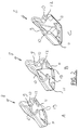
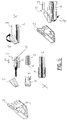
- FIG. 1 shows a preferred variant of a windscreen wiper device 1 according to the invention.
- Said windscreen wiper device 1 is built up of an elongated wiper blade 2 made of an elastomeric material.
- Said wiper blade 2 comprises a central longitudinal groove 3, in which a longitudinal strip 4 or flexor made of spring band steel is fitted.
- Said strip 4 forms a flexible carrier element for the rubber wiper blade 2, as it were, which is thus biased in a curved position (the curvature in operative position being that of a windscreen to be wiped).
- the windscreen wiper device 1 is further equipped with a connecting device 5 for an oscillating arm 6, and a spoiler 7 made in one piece with said wiper blade 2. At both ends of said wiper blade 2, that is on either side of the windscreen wiper device 1, connecting pieces 8 are provided.
- said connecting pieces or end caps 8 each have a bending stiffness in transverse or lateral direction.
- Said internal reinforcement rib 9 enhances the stiffness of said end cap 8 in transverse or lateral direction, allowing said end cap 8 to firmly retain said wiping blade 2 thereon.
- each end cap 8 are provided with engaging members 11 made integral therewith, wherein said engaging members 11 engage around an upper part of said wiper blade 2, so as to form a groove 12 for sliding said upper part therein (embodiments A and B) or by rotating said upper part therein (embodiment C).
- said engaging means 11 include sidewardly extending gripping teeth 13 made integral therewith, wherein said gripping teeth 13 grip into an intermediate web of said wiper blade 2. It is noted that the teeth 13 may only slightly penetrate the elastomeric (rubber) material of said wiper blade 2, without damaging the same.
- end caps 8 are connected to the wiper blade 2 without any connection between said end caps 8 and the strip 4.
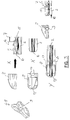
- said spoiler 7 is removed along a portion 14 of the length of said wiper blade 2 at a distance from a free end of said wiper blade 2 facing said end cap 8, so as to form a transverse slit 15.
- Mounting of said end cap 8 onto said free end of said wiper blade 2 is realized as follows. First, said end cap 5 is freely slided onto the respective free end of said wiper blade 2 (side view of situation X and bottom view of situation X) until said reinforcement rib 9 is snapped or "clicked" into said transverse slit 15 (bottom view of situation Y).
- said free end of said wiper blade 2 at the location of said upper part thereof is cut in order to have a curved extremity, so that said upper part of said wiper blade 2 (designated with reference numeral 16) is able to follow a curvature of said end wall 17 of said end cap 8.
- said wiper blade 2 is pinched at a location 18 thereof in order to pull said wiper blade 2 in outward direction.
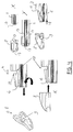
- Figure 4 corresponds to figure 3 , wherein corresponding parts have been designated with the same reference numerals, on the understanding that in figure 3 a part of said spoiler 7 extending from the free end of said wiper blade 2 to said slit 15 has an inclined upper surface 19 with an inclination angle of 5°, whereas in figure 4 said inclined upper surface 19 has an inclination angle of 20°.
- Figure 5 corresponds to figures 3 and 4 , wherein corresponding parts have been designated with the same reference numerals, on the understanding that in figure 5 a part of said spoiler 7 extending from the free end of said wiper blade 2 to said slit 15 has an inclined upper surface 19 having a certain curvature.
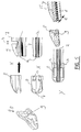
- Figure 6 corresponds to figures 3 , 4 and 5 , wherein corresponding parts have been designated with the same reference numerals, on the understanding that in figure 6 said connecting piece 8 is connected to said wiper blade 2 by rotating said connecting piece 8 onto said wiper blade 2 (side view of situation X) until said reinforcement rib 9 rests inside said transverse slit 15 (bottom view of situation Y). Glue may be used to further retain said end cap 8 onto said wiper blade 2.
- said oscillating arm 6 is connected to a mounting head fixed for rotation to a shaft driven by a small motor.
- the shaft rotates alternately in a clockwise and in a counter-clockwise sense carrying the mounting head into rotation also, which in turn draws said oscillating arm 8 into rotation and by means of said connecting device 5 moves said wiper blade 2.
Landscapes
- Engineering & Computer Science (AREA)
- Mechanical Engineering (AREA)
- Physics & Mathematics (AREA)
- Fluid Mechanics (AREA)
- Quality & Reliability (AREA)
- Transmission Devices (AREA)
- Seal Device For Vehicle (AREA)
- Cleaning In General (AREA)
- Pivots And Pivotal Connections (AREA)
- Cleaning Implements For Floors, Carpets, Furniture, Walls, And The Like (AREA)
- Body Structure For Vehicles (AREA)
- Structures Of Non-Positive Displacement Pumps (AREA)
Claims (15)
- Dispositif d'essuie-glace (1) du type à lame plate comprenant un élément de support allongé élastique, ainsi qu'une lame d'essuie-glace (2) allongée en un matériau souple, qui peut être placée en butée contre un pare-brise à essuyer, laquelle lame d'essuie-glace (2) comprend au moins une rainure (3), dans laquelle rainure (3) une bande longitudinale (4) de l'élément de support est disposée, dans lequel les extrémités libres de ladite lame d'essuie-glace (2) sont reliées à une pièce de liaison (8) respective, lequel dispositif d'essuie-glace (1) comprend un dispositif de liaison (5) pour un bras d'essuie-glace oscillant (6), et dans lequel ladite lame d'essuie-glace (2) est pourvue d'un déflecteur (7) d'un côté de celle-ci orienté à l'opposé dudit pare-brise à essuyer, dans lequel au moins une pièce de liaison (8) comprend une nervure de renforcement transversale interne (9), caractérisé en ce que ledit déflecteur (7) est retiré le long d'une partie (14) de la longueur de ladite lame d'essuie-glace (2) à une distance d'une extrémité libre de ladite lame d'essuie-glace (2) faisant face à ladite pièce de liaison (8) de manière à former une fente transversale (15), et dans lequel, dans la position montée, ladite nervure de renforcement transversale interne (9) repose à l'intérieur de ladite fente (15).
- Dispositif d'essuie-glace (1) selon la revendication 1, dans lequel la hauteur de ladite fente (15) correspond à la hauteur de ladite nervure de renforcement transversale interne (9).
- Dispositif d'essuie-glace (1) selon la revendication 2, dans lequel une partie dudit déflecteur s'étendant de l'extrémité libre de ladite lame d'essuie-glace (2) jusqu'à ladite fente (15) comporte une surface supérieure inclinée (19) avec un angle d'inclinaison compris dans la plage de 0 à 15°.
- Dispositif d'essuie-glace (1) selon la revendication 3, dans lequel ladite surface supérieure inclinée (19) est droite ou incurvée.
- Dispositif d'essuie-glace (1) selon la revendication 1, dans lequel la hauteur de ladite fente (15) est plus grande que la hauteur de ladite nervure de renforcement transversale interne (9).
- Dispositif d'essuie-glace (1) selon la revendication 5, dans lequel une partie dudit déflecteur s'étendant de l'extrémité libre de ladite lame d'essuie-glace (2) jusqu'à ladite fente (15) comporte une surface supérieure inclinée (19) avec un angle d'inclinaison compris dans la plage de 0 à 45°.
- Dispositif d'essuie-glace (1) selon la revendication 6, dans lequel ladite surface supérieure inclinée (19) est droite ou incurvée.
- Procédé pour le montage d'une pièce de liaison (8) sur une lame d'essuie-glace (2) d'un dispositif d'essuie-glace (1) selon l'une quelconque des revendications 1 à 7 précédentes, dans lequel, lors du montage de ladite pièce de liaison (8), ladite lame d'essuie-glace (2), à un emplacement faisant face à ladite pièce de liaison (8), est extraite vers l'extérieur de manière à permettre à ladite nervure de renforcement transversale interne (9) de se déplacer dans ladite fente transversale (15).
- Procédé selon la revendication 8, dans lequel ladite pièce de liaison (8) est reliée à ladite lame d'essuie-glace (2) par une opération de pression en faisant glisser ladite pièce de liaison (8) sur ladite lame d'essuie-glace (2) dans la direction longitudinale de celle-ci jusqu'à ce que ladite nervure de renforcement (9) soit pressée dans ladite fente transversale (15).
- Procédé selon la revendication 8, dans lequel ladite pièce de liaison (8) est reliée à ladite lame d'essuie-glace (2) en faisant tourner ladite pièce de liaison (8) sur ladite lame d'essuie-glace (2) jusqu'à ce que ladite nervure de renforcement (9) repose à l'intérieur de ladite fente transversale (15).
- Dispositif d'essuie-glace (1) selon l'une quelconque des revendications 1 à 7 précédentes, dans lequel ladite pièce de liaison (8) comprend des éléments de mise en prise (11) qui viennent en prise latéralement avec ladite lame d'essuie-glace (2) à partir de l'extérieur, dans lequel lesdits éléments de mise en prise (11) comprennent des moyens de retenue pour retenir ladite lame d'essuie-glace (2) sur ladite pièce de liaison (8).
- Dispositif d'essuie-glace (1) selon la revendication 11, dans lequel lesdits moyens de mise en prise (11) et lesdits moyens de retenue sont d'un seul tenant.
- Dispositif d'essuie-glace (1) selon la revendication 12, dans lequel lesdits éléments de mise en prise (11) et lesdits moyens de retenue sont formés par les parties pliées vers l'intérieur des bords des côtés latéraux (10) de ladite pièce de liaison (8).
- Dispositif d'essuie-glace (1) selon les revendications 11, 12 et 13, dans lequel un plan transversal à travers une extrémité libre de ladite nervure de renforcement transversale interne (9) s'étend à travers lesdits moyens de retenue.
- Dispositif d'essuie-glace (1) selon l'une quelconque des revendications 11 à 14 précédentes, dans lequel lesdits moyens de retenue comprennent au moins une dent d'accrochage (13) s'étendant latéralement pour accrocher une bande intermédiaire de ladite lame d'essuie-glace (2).
Priority Applications (3)
| Application Number | Priority Date | Filing Date | Title |
|---|---|---|---|
| HUE11794515A HUE029146T2 (hu) | 2011-12-15 | 2011-12-15 | Ablaktörlõ elrendezés és eljárás annak összeszerelésére |
| PL11794515T PL2790971T3 (pl) | 2011-12-15 | 2011-12-15 | Urządzenie wycieraczki szyby przedniej i sposób jego montażu |
| SI201130974A SI2790971T1 (sl) | 2011-12-15 | 2011-12-15 | Vetrobranska brisalna naprava in postopek za njeno montažo |
Applications Claiming Priority (1)
| Application Number | Priority Date | Filing Date | Title |
|---|---|---|---|
| PCT/EP2011/072901 WO2013087109A1 (fr) | 2011-12-15 | 2011-12-15 | Dispositif d'essuie-glace |
Publications (2)
| Publication Number | Publication Date |
|---|---|
| EP2790971A1 EP2790971A1 (fr) | 2014-10-22 |
| EP2790971B1 true EP2790971B1 (fr) | 2016-07-27 |
Family
ID=45319133
Family Applications (1)
| Application Number | Title | Priority Date | Filing Date |
|---|---|---|---|
| EP11794515.4A Active EP2790971B1 (fr) | 2011-12-15 | 2011-12-15 | Dispositif d'essuie-glace et son procédé d'assemblage |
Country Status (15)
| Country | Link |
|---|---|
| US (1) | US9919683B2 (fr) |
| EP (1) | EP2790971B1 (fr) |
| JP (1) | JP2015500173A (fr) |
| KR (1) | KR101948960B1 (fr) |
| CN (1) | CN103987590B (fr) |
| BR (1) | BR112014014395A2 (fr) |
| CA (1) | CA2857979A1 (fr) |
| ES (1) | ES2597055T3 (fr) |
| HU (1) | HUE029146T2 (fr) |
| IN (1) | IN2014DN04649A (fr) |
| MX (1) | MX345108B (fr) |
| PL (1) | PL2790971T3 (fr) |
| RU (1) | RU2571155C1 (fr) |
| SI (1) | SI2790971T1 (fr) |
| WO (1) | WO2013087109A1 (fr) |
Families Citing this family (6)
| Publication number | Priority date | Publication date | Assignee | Title |
|---|---|---|---|---|
| DE102013212781A1 (de) * | 2013-07-01 | 2015-01-08 | Robert Bosch Gmbh | Wischblattvorrichtung |
| US9421951B2 (en) * | 2014-05-29 | 2016-08-23 | Trico Products Corporation | Wiper assembly having an end cap |
| DE102015114928A1 (de) * | 2015-09-07 | 2017-03-09 | Valeo Systèmes d'Essuyage | Reinigungseinrichtung zum Reinigen von Fahrzeugscheiben und Wischvorrichtung |
| EP3655636B1 (fr) | 2017-07-21 | 2021-11-24 | Dresser Rand Company | Atténuateur acoustique pour une turbomachine et méthodologie de fabrication additive dudit atténuateur acoustique |
| FR3069508B1 (fr) * | 2017-07-26 | 2020-09-04 | Valeo Systemes Dessuyage | Balai d’essuie-glace de vehicule |
| EP4010229B1 (fr) * | 2019-08-06 | 2024-07-17 | Trico Belgium S.A. | Dispositif d'essuie-glace du type à lame plate |
Citations (9)
| Publication number | Priority date | Publication date | Assignee | Title |
|---|---|---|---|---|
| DE4228284A1 (de) | 1991-09-09 | 1993-03-11 | Journee Paul Sa | Scheibenwischerleiste mit mitteln zur laengsarretierung des wischblatts |
| US6523218B1 (en) | 1998-12-07 | 2003-02-25 | Robert Bosch Gmbh | Wiper blade for window panes of motor vehicles |
| JP2005059644A (ja) | 2003-08-08 | 2005-03-10 | Nippon Wiper Blade Co Ltd | ワイパーブレード |
| FR2905650A1 (fr) | 2006-09-11 | 2008-03-14 | Valeo Systemes Dessuyage | Balai d'essuie-glace avec verrou de balai. |
| US20090013492A1 (en) | 2005-03-02 | 2009-01-15 | Federal-Mogul S.A. | Windscreen wiper device |
| DE102008017249A1 (de) | 2008-04-04 | 2009-10-08 | Volkswagen Ag | Wischerblatt für einen Scheibenwischer an einem Fahrzeug |
| DE102009029432A1 (de) | 2009-09-14 | 2011-03-24 | Robert Bosch Gmbh | Wischblatt in Flachbalkenbauweise |
| DE102010042095A1 (de) | 2009-10-09 | 2011-04-14 | Robert Bosch Gmbh | Wischblatt |
| WO2013087098A1 (fr) | 2011-12-14 | 2013-06-20 | Federal-Mogul S.A. | Dispositif d'essuie-glace |
Family Cites Families (13)
| Publication number | Priority date | Publication date | Assignee | Title |
|---|---|---|---|---|
| ES2246324T3 (es) * | 2000-05-29 | 2006-02-16 | Robert Bosch Gmbh | Hoja de limpiaparabrisas para la limpieza de cristales, especialmente de automoviles. |
| DE10033778A1 (de) * | 2000-07-12 | 2002-04-18 | Valeo Auto Electric Gmbh | Wischvorrichtung |
| DE10122764B4 (de) * | 2001-05-10 | 2016-08-25 | Valeo Auto-Electric Wischer Und Motoren Gmbh | Wischvorrichtung |
| EP1491416B1 (fr) * | 2003-06-26 | 2006-11-29 | Federal-Mogul S.A. | Dispositif d'essuie-glace |
| DE10332775A1 (de) | 2003-07-17 | 2005-02-17 | Sasol Germany Gmbh | Verfahren zur Herstellung böhmitischer Tonerden mit hoher a-Umwandlungstemperatur |
| JP2007313908A (ja) * | 2004-11-09 | 2007-12-06 | Mitsuba Corp | ワイパブレード |
| CN101010227A (zh) * | 2004-09-02 | 2007-08-01 | 贝卡尔特股份有限公司 | 用于风窗玻璃刮水器的橡胶刮水片的支架的异形轨 |
| US7150066B1 (en) * | 2005-06-15 | 2006-12-19 | Shih Hsien Huang | Windshield wiper structure for vehicles |
| FR2893290B1 (fr) * | 2005-09-13 | 2009-05-01 | Valeo Systemes Dessuyage | Dispositif de verrouillage entre une lame d'essuyage et un porte-balai d'essuie-glace |
| WO2007122569A2 (fr) * | 2006-04-21 | 2007-11-01 | Teklas Kaucuk Sanayi Ve Ticaret A.S. | Coiffes d'extrémité utilisées dans des essuie-glaces pour véhicules |
| DE102006048724A1 (de) * | 2006-10-16 | 2008-04-17 | Robert Bosch Gmbh | Wischblatt |
| EP2098420A1 (fr) * | 2008-03-08 | 2009-09-09 | Mecatech (SA) | Lame d'essuyage universelle pour balai d'essuie-glace |
| DE102011076362A1 (de) * | 2011-05-24 | 2012-11-29 | Robert Bosch Gmbh | Wischblatt |
-
2011
- 2011-12-15 BR BR112014014395A patent/BR112014014395A2/pt not_active IP Right Cessation
- 2011-12-15 EP EP11794515.4A patent/EP2790971B1/fr active Active
- 2011-12-15 MX MX2014006997A patent/MX345108B/es active IP Right Grant
- 2011-12-15 WO PCT/EP2011/072901 patent/WO2013087109A1/fr active Application Filing
- 2011-12-15 HU HUE11794515A patent/HUE029146T2/hu unknown
- 2011-12-15 US US14/365,733 patent/US9919683B2/en not_active Expired - Fee Related
- 2011-12-15 KR KR1020147017343A patent/KR101948960B1/ko active IP Right Grant
- 2011-12-15 SI SI201130974A patent/SI2790971T1/sl unknown
- 2011-12-15 ES ES11794515.4T patent/ES2597055T3/es active Active
- 2011-12-15 RU RU2014128895/11A patent/RU2571155C1/ru not_active IP Right Cessation
- 2011-12-15 PL PL11794515T patent/PL2790971T3/pl unknown
- 2011-12-15 CN CN201180075584.3A patent/CN103987590B/zh not_active Expired - Fee Related
- 2011-12-15 JP JP2014546333A patent/JP2015500173A/ja active Pending
- 2011-12-15 CA CA2857979A patent/CA2857979A1/fr not_active Abandoned
-
2014
- 2014-06-09 IN IN4649DEN2014 patent/IN2014DN04649A/en unknown
Patent Citations (9)
| Publication number | Priority date | Publication date | Assignee | Title |
|---|---|---|---|---|
| DE4228284A1 (de) | 1991-09-09 | 1993-03-11 | Journee Paul Sa | Scheibenwischerleiste mit mitteln zur laengsarretierung des wischblatts |
| US6523218B1 (en) | 1998-12-07 | 2003-02-25 | Robert Bosch Gmbh | Wiper blade for window panes of motor vehicles |
| JP2005059644A (ja) | 2003-08-08 | 2005-03-10 | Nippon Wiper Blade Co Ltd | ワイパーブレード |
| US20090013492A1 (en) | 2005-03-02 | 2009-01-15 | Federal-Mogul S.A. | Windscreen wiper device |
| FR2905650A1 (fr) | 2006-09-11 | 2008-03-14 | Valeo Systemes Dessuyage | Balai d'essuie-glace avec verrou de balai. |
| DE102008017249A1 (de) | 2008-04-04 | 2009-10-08 | Volkswagen Ag | Wischerblatt für einen Scheibenwischer an einem Fahrzeug |
| DE102009029432A1 (de) | 2009-09-14 | 2011-03-24 | Robert Bosch Gmbh | Wischblatt in Flachbalkenbauweise |
| DE102010042095A1 (de) | 2009-10-09 | 2011-04-14 | Robert Bosch Gmbh | Wischblatt |
| WO2013087098A1 (fr) | 2011-12-14 | 2013-06-20 | Federal-Mogul S.A. | Dispositif d'essuie-glace |
Also Published As
| Publication number | Publication date |
|---|---|
| RU2571155C1 (ru) | 2015-12-20 |
| CN103987590A (zh) | 2014-08-13 |
| BR112014014395A2 (pt) | 2017-06-13 |
| SI2790971T1 (sl) | 2016-11-30 |
| US20150026910A1 (en) | 2015-01-29 |
| CN103987590B (zh) | 2017-07-28 |
| KR20140106600A (ko) | 2014-09-03 |
| EP2790971A1 (fr) | 2014-10-22 |
| US9919683B2 (en) | 2018-03-20 |
| MX345108B (es) | 2017-01-17 |
| MX2014006997A (es) | 2014-10-24 |
| WO2013087109A1 (fr) | 2013-06-20 |
| CA2857979A1 (fr) | 2013-06-20 |
| PL2790971T3 (pl) | 2017-03-31 |
| IN2014DN04649A (fr) | 2015-04-03 |
| ES2597055T3 (es) | 2017-01-13 |
| JP2015500173A (ja) | 2015-01-05 |
| KR101948960B1 (ko) | 2019-02-15 |
| HUE029146T2 (hu) | 2017-02-28 |
Similar Documents
| Publication | Publication Date | Title |
|---|---|---|
| EP2790971B1 (fr) | Dispositif d'essuie-glace et son procédé d'assemblage | |
| EP2106979B1 (fr) | Dispositif essuie-glace comprenant un élément support allongé, élastique ainsi qu'un balai d'essuie-glace allongé qui peut être placé en butée avec le pare-brise à essuyer | |
| EP1491416B1 (fr) | Dispositif d'essuie-glace | |
| EP2536602B1 (fr) | Dispositif d'essuie-glace de pare-brise | |
| US20160101762A1 (en) | Windscreen wiper device | |
| EP2790972B1 (fr) | Dispositif d'essuie-glace | |
| EP2168823B1 (fr) | Dispositif d'essuie-glace | |
| EP2922734B1 (fr) | Dispositif d'essuie-glace de pare-brise | |
| EP2670635B1 (fr) | Dispositif d'essuie-glace | |
| WO2018095521A1 (fr) | Dispositif d'essuie-glace |
Legal Events
| Date | Code | Title | Description |
|---|---|---|---|
| PUAI | Public reference made under article 153(3) epc to a published international application that has entered the european phase |
Free format text: ORIGINAL CODE: 0009012 |
|
| 17P | Request for examination filed |
Effective date: 20140610 |
|
| AK | Designated contracting states |
Kind code of ref document: A1 Designated state(s): AL AT BE BG CH CY CZ DE DK EE ES FI FR GB GR HR HU IE IS IT LI LT LU LV MC MK MT NL NO PL PT RO RS SE SI SK SM TR |
|
| DAX | Request for extension of the european patent (deleted) | ||
| 17Q | First examination report despatched |
Effective date: 20150703 |
|
| GRAP | Despatch of communication of intention to grant a patent |
Free format text: ORIGINAL CODE: EPIDOSNIGR1 |
|
| INTG | Intention to grant announced |
Effective date: 20160226 |
|
| GRAS | Grant fee paid |
Free format text: ORIGINAL CODE: EPIDOSNIGR3 |
|
| GRAA | (expected) grant |
Free format text: ORIGINAL CODE: 0009210 |
|
| AK | Designated contracting states |
Kind code of ref document: B1 Designated state(s): AL AT BE BG CH CY CZ DE DK EE ES FI FR GB GR HR HU IE IS IT LI LT LU LV MC MK MT NL NO PL PT RO RS SE SI SK SM TR |
|
| REG | Reference to a national code |
Ref country code: GB Ref legal event code: FG4D |
|
| REG | Reference to a national code |
Ref country code: CH Ref legal event code: EP |
|
| REG | Reference to a national code |
Ref country code: AT Ref legal event code: REF Ref document number: 815526 Country of ref document: AT Kind code of ref document: T Effective date: 20160815 |
|
| REG | Reference to a national code |
Ref country code: IE Ref legal event code: FG4D |
|
| REG | Reference to a national code |
Ref country code: DE Ref legal event code: R096 Ref document number: 602011028627 Country of ref document: DE |
|
| REG | Reference to a national code |
Ref country code: NL Ref legal event code: FP |
|
| REG | Reference to a national code |
Ref country code: RO Ref legal event code: EPE |
|
| REG | Reference to a national code |
Ref country code: SE Ref legal event code: TRGR |
|
| REG | Reference to a national code |
Ref country code: FR Ref legal event code: PLFP Year of fee payment: 6 |
|
| REG | Reference to a national code |
Ref country code: LT Ref legal event code: MG4D |
|
| REG | Reference to a national code |
Ref country code: AT Ref legal event code: MK05 Ref document number: 815526 Country of ref document: AT Kind code of ref document: T Effective date: 20160727 |
|
| REG | Reference to a national code |
Ref country code: ES Ref legal event code: FG2A Ref document number: 2597055 Country of ref document: ES Kind code of ref document: T3 Effective date: 20170113 |
|
| PG25 | Lapsed in a contracting state [announced via postgrant information from national office to epo] |
Ref country code: IS Free format text: LAPSE BECAUSE OF FAILURE TO SUBMIT A TRANSLATION OF THE DESCRIPTION OR TO PAY THE FEE WITHIN THE PRESCRIBED TIME-LIMIT Effective date: 20161127 Ref country code: NO Free format text: LAPSE BECAUSE OF FAILURE TO SUBMIT A TRANSLATION OF THE DESCRIPTION OR TO PAY THE FEE WITHIN THE PRESCRIBED TIME-LIMIT Effective date: 20161027 Ref country code: RS Free format text: LAPSE BECAUSE OF FAILURE TO SUBMIT A TRANSLATION OF THE DESCRIPTION OR TO PAY THE FEE WITHIN THE PRESCRIBED TIME-LIMIT Effective date: 20160727 Ref country code: LT Free format text: LAPSE BECAUSE OF FAILURE TO SUBMIT A TRANSLATION OF THE DESCRIPTION OR TO PAY THE FEE WITHIN THE PRESCRIBED TIME-LIMIT Effective date: 20160727 Ref country code: FI Free format text: LAPSE BECAUSE OF FAILURE TO SUBMIT A TRANSLATION OF THE DESCRIPTION OR TO PAY THE FEE WITHIN THE PRESCRIBED TIME-LIMIT Effective date: 20160727 Ref country code: HR Free format text: LAPSE BECAUSE OF FAILURE TO SUBMIT A TRANSLATION OF THE DESCRIPTION OR TO PAY THE FEE WITHIN THE PRESCRIBED TIME-LIMIT Effective date: 20160727 |
|
| PGFP | Annual fee paid to national office [announced via postgrant information from national office to epo] |
Ref country code: HU Payment date: 20161124 Year of fee payment: 6 Ref country code: NL Payment date: 20161207 Year of fee payment: 6 |
|
| PG25 | Lapsed in a contracting state [announced via postgrant information from national office to epo] |
Ref country code: LV Free format text: LAPSE BECAUSE OF FAILURE TO SUBMIT A TRANSLATION OF THE DESCRIPTION OR TO PAY THE FEE WITHIN THE PRESCRIBED TIME-LIMIT Effective date: 20160727 Ref country code: PT Free format text: LAPSE BECAUSE OF FAILURE TO SUBMIT A TRANSLATION OF THE DESCRIPTION OR TO PAY THE FEE WITHIN THE PRESCRIBED TIME-LIMIT Effective date: 20161128 Ref country code: GR Free format text: LAPSE BECAUSE OF FAILURE TO SUBMIT A TRANSLATION OF THE DESCRIPTION OR TO PAY THE FEE WITHIN THE PRESCRIBED TIME-LIMIT Effective date: 20161028 Ref country code: AT Free format text: LAPSE BECAUSE OF FAILURE TO SUBMIT A TRANSLATION OF THE DESCRIPTION OR TO PAY THE FEE WITHIN THE PRESCRIBED TIME-LIMIT Effective date: 20160727 |
|
| PGFP | Annual fee paid to national office [announced via postgrant information from national office to epo] |
Ref country code: SI Payment date: 20161208 Year of fee payment: 6 Ref country code: SE Payment date: 20161207 Year of fee payment: 6 Ref country code: RO Payment date: 20161115 Year of fee payment: 6 Ref country code: ES Payment date: 20161215 Year of fee payment: 6 |
|
| REG | Reference to a national code |
Ref country code: HU Ref legal event code: AG4A Ref document number: E029146 Country of ref document: HU |
|
| REG | Reference to a national code |
Ref country code: SK Ref legal event code: T3 Ref document number: E 22588 Country of ref document: SK |
|
| PG25 | Lapsed in a contracting state [announced via postgrant information from national office to epo] |
Ref country code: EE Free format text: LAPSE BECAUSE OF FAILURE TO SUBMIT A TRANSLATION OF THE DESCRIPTION OR TO PAY THE FEE WITHIN THE PRESCRIBED TIME-LIMIT Effective date: 20160727 |
|
| REG | Reference to a national code |
Ref country code: DE Ref legal event code: R026 Ref document number: 602011028627 Country of ref document: DE |
|
| PLBI | Opposition filed |
Free format text: ORIGINAL CODE: 0009260 |
|
| PG25 | Lapsed in a contracting state [announced via postgrant information from national office to epo] |
Ref country code: SM Free format text: LAPSE BECAUSE OF FAILURE TO SUBMIT A TRANSLATION OF THE DESCRIPTION OR TO PAY THE FEE WITHIN THE PRESCRIBED TIME-LIMIT Effective date: 20160727 Ref country code: DK Free format text: LAPSE BECAUSE OF FAILURE TO SUBMIT A TRANSLATION OF THE DESCRIPTION OR TO PAY THE FEE WITHIN THE PRESCRIBED TIME-LIMIT Effective date: 20160727 Ref country code: BG Free format text: LAPSE BECAUSE OF FAILURE TO SUBMIT A TRANSLATION OF THE DESCRIPTION OR TO PAY THE FEE WITHIN THE PRESCRIBED TIME-LIMIT Effective date: 20161027 |
|
| PGFP | Annual fee paid to national office [announced via postgrant information from national office to epo] |
Ref country code: SK Payment date: 20161124 Year of fee payment: 6 |
|
| PLAX | Notice of opposition and request to file observation + time limit sent |
Free format text: ORIGINAL CODE: EPIDOSNOBS2 |
|
| 26 | Opposition filed |
Opponent name: VALEO SYSTEMES D'ESSUYAGE Effective date: 20170428 |
|
| REG | Reference to a national code |
Ref country code: CH Ref legal event code: PL |
|
| PG25 | Lapsed in a contracting state [announced via postgrant information from national office to epo] |
Ref country code: MC Free format text: LAPSE BECAUSE OF FAILURE TO SUBMIT A TRANSLATION OF THE DESCRIPTION OR TO PAY THE FEE WITHIN THE PRESCRIBED TIME-LIMIT Effective date: 20160727 |
|
| REG | Reference to a national code |
Ref country code: IE Ref legal event code: MM4A |
|
| PLBB | Reply of patent proprietor to notice(s) of opposition received |
Free format text: ORIGINAL CODE: EPIDOSNOBS3 |
|
| PG25 | Lapsed in a contracting state [announced via postgrant information from national office to epo] |
Ref country code: LU Free format text: LAPSE BECAUSE OF NON-PAYMENT OF DUE FEES Effective date: 20161215 Ref country code: LI Free format text: LAPSE BECAUSE OF NON-PAYMENT OF DUE FEES Effective date: 20161231 Ref country code: CH Free format text: LAPSE BECAUSE OF NON-PAYMENT OF DUE FEES Effective date: 20161231 |
|
| REG | Reference to a national code |
Ref country code: FR Ref legal event code: PLFP Year of fee payment: 7 |
|
| PG25 | Lapsed in a contracting state [announced via postgrant information from national office to epo] |
Ref country code: IE Free format text: LAPSE BECAUSE OF NON-PAYMENT OF DUE FEES Effective date: 20161215 |
|
| PG25 | Lapsed in a contracting state [announced via postgrant information from national office to epo] |
Ref country code: MK Free format text: LAPSE BECAUSE OF FAILURE TO SUBMIT A TRANSLATION OF THE DESCRIPTION OR TO PAY THE FEE WITHIN THE PRESCRIBED TIME-LIMIT Effective date: 20160727 Ref country code: CY Free format text: LAPSE BECAUSE OF FAILURE TO SUBMIT A TRANSLATION OF THE DESCRIPTION OR TO PAY THE FEE WITHIN THE PRESCRIBED TIME-LIMIT Effective date: 20160727 |
|
| REG | Reference to a national code |
Ref country code: NL Ref legal event code: MM Effective date: 20180101 |
|
| GBPC | Gb: european patent ceased through non-payment of renewal fee |
Effective date: 20171215 |
|
| PG25 | Lapsed in a contracting state [announced via postgrant information from national office to epo] |
Ref country code: SE Free format text: LAPSE BECAUSE OF NON-PAYMENT OF DUE FEES Effective date: 20171216 |
|
| PG25 | Lapsed in a contracting state [announced via postgrant information from national office to epo] |
Ref country code: NL Free format text: LAPSE BECAUSE OF NON-PAYMENT OF DUE FEES Effective date: 20180101 Ref country code: MT Free format text: LAPSE BECAUSE OF NON-PAYMENT OF DUE FEES Effective date: 20161215 |
|
| REG | Reference to a national code |
Ref country code: SI Ref legal event code: KO00 Effective date: 20180806 |
|
| REG | Reference to a national code |
Ref country code: DE Ref legal event code: R100 Ref document number: 602011028627 Country of ref document: DE |
|
| PG25 | Lapsed in a contracting state [announced via postgrant information from national office to epo] |
Ref country code: HU Free format text: LAPSE BECAUSE OF NON-PAYMENT OF DUE FEES Effective date: 20171216 Ref country code: AL Free format text: LAPSE BECAUSE OF FAILURE TO SUBMIT A TRANSLATION OF THE DESCRIPTION OR TO PAY THE FEE WITHIN THE PRESCRIBED TIME-LIMIT Effective date: 20160727 |
|
| PLCK | Communication despatched that opposition was rejected |
Free format text: ORIGINAL CODE: EPIDOSNREJ1 |
|
| STAA | Information on the status of an ep patent application or granted ep patent |
Free format text: STATUS: THE PATENT HAS BEEN GRANTED |
|
| PG25 | Lapsed in a contracting state [announced via postgrant information from national office to epo] |
Ref country code: SI Free format text: LAPSE BECAUSE OF NON-PAYMENT OF DUE FEES Effective date: 20171216 Ref country code: GB Free format text: LAPSE BECAUSE OF NON-PAYMENT OF DUE FEES Effective date: 20171215 |
|
| PGFP | Annual fee paid to national office [announced via postgrant information from national office to epo] |
Ref country code: GB Payment date: 20181107 Year of fee payment: 18 |
|
| PLBN | Opposition rejected |
Free format text: ORIGINAL CODE: 0009273 |
|
| STAA | Information on the status of an ep patent application or granted ep patent |
Free format text: STATUS: OPPOSITION REJECTED |
|
| 27O | Opposition rejected |
Effective date: 20181024 |
|
| REG | Reference to a national code |
Ref country code: ES Ref legal event code: FD2A Effective date: 20190703 |
|
| PG25 | Lapsed in a contracting state [announced via postgrant information from national office to epo] |
Ref country code: ES Free format text: LAPSE BECAUSE OF NON-PAYMENT OF DUE FEES Effective date: 20171216 |
|
| PG25 | Lapsed in a contracting state [announced via postgrant information from national office to epo] |
Ref country code: RO Free format text: LAPSE BECAUSE OF NON-PAYMENT OF DUE FEES Effective date: 20171212 |
|
| REG | Reference to a national code |
Ref country code: SK Ref legal event code: MM4A Ref document number: E 22588 Country of ref document: SK Effective date: 20171215 |
|
| PG25 | Lapsed in a contracting state [announced via postgrant information from national office to epo] |
Ref country code: SK Free format text: LAPSE BECAUSE OF NON-PAYMENT OF DUE FEES Effective date: 20171215 |
|
| PGFP | Annual fee paid to national office [announced via postgrant information from national office to epo] |
Ref country code: CZ Payment date: 20191212 Year of fee payment: 9 |
|
| PGFP | Annual fee paid to national office [announced via postgrant information from national office to epo] |
Ref country code: IT Payment date: 20191209 Year of fee payment: 9 Ref country code: PL Payment date: 20191016 Year of fee payment: 9 |
|
| PG25 | Lapsed in a contracting state [announced via postgrant information from national office to epo] |
Ref country code: CZ Free format text: LAPSE BECAUSE OF NON-PAYMENT OF DUE FEES Effective date: 20201215 |
|
| PGFP | Annual fee paid to national office [announced via postgrant information from national office to epo] |
Ref country code: FR Payment date: 20210629 Year of fee payment: 10 |
|
| PG25 | Lapsed in a contracting state [announced via postgrant information from national office to epo] |
Ref country code: IT Free format text: LAPSE BECAUSE OF NON-PAYMENT OF DUE FEES Effective date: 20201215 |
|
| PGFP | Annual fee paid to national office [announced via postgrant information from national office to epo] |
Ref country code: BE Payment date: 20210702 Year of fee payment: 10 |
|
| PG25 | Lapsed in a contracting state [announced via postgrant information from national office to epo] |
Ref country code: TR Free format text: LAPSE BECAUSE OF NON-PAYMENT OF DUE FEES Effective date: 20201215 |
|
| REG | Reference to a national code |
Ref country code: BE Ref legal event code: MM Effective date: 20211231 |
|
| PG25 | Lapsed in a contracting state [announced via postgrant information from national office to epo] |
Ref country code: PL Free format text: LAPSE BECAUSE OF NON-PAYMENT OF DUE FEES Effective date: 20201215 Ref country code: FR Free format text: LAPSE BECAUSE OF NON-PAYMENT OF DUE FEES Effective date: 20211231 Ref country code: BE Free format text: LAPSE BECAUSE OF NON-PAYMENT OF DUE FEES Effective date: 20211231 |
|
| PGFP | Annual fee paid to national office [announced via postgrant information from national office to epo] |
Ref country code: DE Payment date: 20231229 Year of fee payment: 13 |