EP2788646B2 - Conduite à fluide confectionnée et procédé de confection d'une conduite à fluide pourvue d'éléments de chauffe internes - Google Patents
Conduite à fluide confectionnée et procédé de confection d'une conduite à fluide pourvue d'éléments de chauffe internes Download PDFInfo
- Publication number
- EP2788646B2 EP2788646B2 EP12809113.9A EP12809113A EP2788646B2 EP 2788646 B2 EP2788646 B2 EP 2788646B2 EP 12809113 A EP12809113 A EP 12809113A EP 2788646 B2 EP2788646 B2 EP 2788646B2
- Authority
- EP
- European Patent Office
- Prior art keywords
- heating elements
- heating
- media
- conduit
- line
- Prior art date
- Legal status (The legal status is an assumption and is not a legal conclusion. Google has not performed a legal analysis and makes no representation as to the accuracy of the status listed.)
- Active
Links
- 238000010438 heat treatment Methods 0.000 title claims description 327
- 238000000034 method Methods 0.000 title claims description 9
- 238000002788 crimping Methods 0.000 claims description 23
- 239000011248 coating agent Substances 0.000 claims description 16
- 238000000576 coating method Methods 0.000 claims description 16
- 238000009413 insulation Methods 0.000 claims description 13
- 238000007789 sealing Methods 0.000 claims description 11
- PXHVJJICTQNCMI-UHFFFAOYSA-N Nickel Chemical compound [Ni] PXHVJJICTQNCMI-UHFFFAOYSA-N 0.000 claims description 10
- 239000004744 fabric Substances 0.000 claims description 10
- 238000005260 corrosion Methods 0.000 claims description 5
- 229920002313 fluoropolymer Polymers 0.000 claims description 5
- 239000004811 fluoropolymer Substances 0.000 claims description 5
- 229910052759 nickel Inorganic materials 0.000 claims description 5
- ATJFFYVFTNAWJD-UHFFFAOYSA-N Tin Chemical compound [Sn] ATJFFYVFTNAWJD-UHFFFAOYSA-N 0.000 claims description 4
- 238000007747 plating Methods 0.000 claims description 4
- 239000004835 fabric adhesive Substances 0.000 claims description 3
- 239000002390 adhesive tape Substances 0.000 claims description 2
- 239000000126 substance Substances 0.000 claims description 2
- 239000004020 conductor Substances 0.000 description 35
- 238000005538 encapsulation Methods 0.000 description 22
- 239000002609 medium Substances 0.000 description 18
- 239000000463 material Substances 0.000 description 12
- 239000004954 Polyphthalamide Substances 0.000 description 6
- 238000005253 cladding Methods 0.000 description 6
- 230000008878 coupling Effects 0.000 description 6
- 238000010168 coupling process Methods 0.000 description 6
- 238000005859 coupling reaction Methods 0.000 description 6
- 239000000835 fiber Substances 0.000 description 6
- 229920006375 polyphtalamide Polymers 0.000 description 6
- 239000012530 fluid Substances 0.000 description 5
- QGZKDVFQNNGYKY-UHFFFAOYSA-N Ammonia Chemical compound N QGZKDVFQNNGYKY-UHFFFAOYSA-N 0.000 description 4
- 239000000853 adhesive Substances 0.000 description 4
- 230000001070 adhesive effect Effects 0.000 description 4
- 239000004760 aramid Substances 0.000 description 4
- 238000005520 cutting process Methods 0.000 description 4
- 230000001681 protective effect Effects 0.000 description 4
- 238000010792 warming Methods 0.000 description 4
- 229920000299 Nylon 12 Polymers 0.000 description 3
- 230000007797 corrosion Effects 0.000 description 3
- 230000008014 freezing Effects 0.000 description 3
- 238000007710 freezing Methods 0.000 description 3
- 238000003780 insertion Methods 0.000 description 3
- 230000037431 insertion Effects 0.000 description 3
- XIUFWXXRTPHHDQ-UHFFFAOYSA-N prop-1-ene;1,1,2,2-tetrafluoroethene Chemical group CC=C.FC(F)=C(F)F XIUFWXXRTPHHDQ-UHFFFAOYSA-N 0.000 description 3
- 238000004804 winding Methods 0.000 description 3
- 229920002943 EPDM rubber Polymers 0.000 description 2
- 229920000271 Kevlar® Polymers 0.000 description 2
- 229910021529 ammonia Inorganic materials 0.000 description 2
- 229920006231 aramid fiber Polymers 0.000 description 2
- 229920003235 aromatic polyamide Polymers 0.000 description 2
- 230000001419 dependent effect Effects 0.000 description 2
- 230000000694 effects Effects 0.000 description 2
- 238000004519 manufacturing process Methods 0.000 description 2
- 230000003446 memory effect Effects 0.000 description 2
- 238000005457 optimization Methods 0.000 description 2
- 238000004382 potting Methods 0.000 description 2
- 229920006346 thermoplastic polyester elastomer Polymers 0.000 description 2
- 238000012546 transfer Methods 0.000 description 2
- 239000002699 waste material Substances 0.000 description 2
- PXGOKWXKJXAPGV-UHFFFAOYSA-N Fluorine Chemical compound FF PXGOKWXKJXAPGV-UHFFFAOYSA-N 0.000 description 1
- 229920002292 Nylon 6 Polymers 0.000 description 1
- 229920011286 PA12 GF30 Polymers 0.000 description 1
- 239000004743 Polypropylene Substances 0.000 description 1
- BQCADISMDOOEFD-UHFFFAOYSA-N Silver Chemical compound [Ag] BQCADISMDOOEFD-UHFFFAOYSA-N 0.000 description 1
- XSQUKJJJFZCRTK-UHFFFAOYSA-N Urea Chemical compound NC(N)=O XSQUKJJJFZCRTK-UHFFFAOYSA-N 0.000 description 1
- 239000000956 alloy Substances 0.000 description 1
- 229910045601 alloy Inorganic materials 0.000 description 1
- 230000006399 behavior Effects 0.000 description 1
- 239000004202 carbamide Substances 0.000 description 1
- 229920003020 cross-linked polyethylene Polymers 0.000 description 1
- 239000004703 cross-linked polyethylene Substances 0.000 description 1
- 238000011161 development Methods 0.000 description 1
- 230000018109 developmental process Effects 0.000 description 1
- 238000006073 displacement reaction Methods 0.000 description 1
- 238000009826 distribution Methods 0.000 description 1
- 239000000945 filler Substances 0.000 description 1
- 229910052731 fluorine Inorganic materials 0.000 description 1
- 239000011737 fluorine Substances 0.000 description 1
- 239000012595 freezing medium Substances 0.000 description 1
- 239000003365 glass fiber Substances 0.000 description 1
- 229910052736 halogen Inorganic materials 0.000 description 1
- 150000002367 halogens Chemical class 0.000 description 1
- 238000013021 overheating Methods 0.000 description 1
- 230000000149 penetrating effect Effects 0.000 description 1
- 229920000642 polymer Polymers 0.000 description 1
- -1 polypropylene Polymers 0.000 description 1
- 229920001155 polypropylene Polymers 0.000 description 1
- 230000005855 radiation Effects 0.000 description 1
- 230000002787 reinforcement Effects 0.000 description 1
- 230000003014 reinforcing effect Effects 0.000 description 1
- 230000002441 reversible effect Effects 0.000 description 1
- 229910052709 silver Inorganic materials 0.000 description 1
- 239000004332 silver Substances 0.000 description 1
- 230000007704 transition Effects 0.000 description 1
Images


Classifications
-
- F—MECHANICAL ENGINEERING; LIGHTING; HEATING; WEAPONS; BLASTING
- F16—ENGINEERING ELEMENTS AND UNITS; GENERAL MEASURES FOR PRODUCING AND MAINTAINING EFFECTIVE FUNCTIONING OF MACHINES OR INSTALLATIONS; THERMAL INSULATION IN GENERAL
- F16L—PIPES; JOINTS OR FITTINGS FOR PIPES; SUPPORTS FOR PIPES, CABLES OR PROTECTIVE TUBING; MEANS FOR THERMAL INSULATION IN GENERAL
- F16L25/00—Constructive types of pipe joints not provided for in groups F16L13/00 - F16L23/00 ; Details of pipe joints not otherwise provided for, e.g. electrically conducting or insulating means
- F16L25/01—Constructive types of pipe joints not provided for in groups F16L13/00 - F16L23/00 ; Details of pipe joints not otherwise provided for, e.g. electrically conducting or insulating means specially adapted for realising electrical conduction between the two pipe ends of the joint or between parts thereof
-
- F—MECHANICAL ENGINEERING; LIGHTING; HEATING; WEAPONS; BLASTING
- F16—ENGINEERING ELEMENTS AND UNITS; GENERAL MEASURES FOR PRODUCING AND MAINTAINING EFFECTIVE FUNCTIONING OF MACHINES OR INSTALLATIONS; THERMAL INSULATION IN GENERAL
- F16L—PIPES; JOINTS OR FITTINGS FOR PIPES; SUPPORTS FOR PIPES, CABLES OR PROTECTIVE TUBING; MEANS FOR THERMAL INSULATION IN GENERAL
- F16L53/00—Heating of pipes or pipe systems; Cooling of pipes or pipe systems
- F16L53/30—Heating of pipes or pipe systems
- F16L53/35—Ohmic-resistance heating
- F16L53/38—Ohmic-resistance heating using elongate electric heating elements, e.g. wires or ribbons
-
- F—MECHANICAL ENGINEERING; LIGHTING; HEATING; WEAPONS; BLASTING
- F24—HEATING; RANGES; VENTILATING
- F24H—FLUID HEATERS, e.g. WATER OR AIR HEATERS, HAVING HEAT-GENERATING MEANS, e.g. HEAT PUMPS, IN GENERAL
- F24H1/00—Water heaters, e.g. boilers, continuous-flow heaters or water-storage heaters
- F24H1/0072—Special adaptations
- F24H1/009—Special adaptations for vehicle systems
-
- F—MECHANICAL ENGINEERING; LIGHTING; HEATING; WEAPONS; BLASTING
- F24—HEATING; RANGES; VENTILATING
- F24H—FLUID HEATERS, e.g. WATER OR AIR HEATERS, HAVING HEAT-GENERATING MEANS, e.g. HEAT PUMPS, IN GENERAL
- F24H1/00—Water heaters, e.g. boilers, continuous-flow heaters or water-storage heaters
- F24H1/10—Continuous-flow heaters, i.e. heaters in which heat is generated only while the water is flowing, e.g. with direct contact of the water with the heating medium
- F24H1/101—Continuous-flow heaters, i.e. heaters in which heat is generated only while the water is flowing, e.g. with direct contact of the water with the heating medium using electric energy supply
- F24H1/102—Continuous-flow heaters, i.e. heaters in which heat is generated only while the water is flowing, e.g. with direct contact of the water with the heating medium using electric energy supply with resistance
-
- H—ELECTRICITY
- H05—ELECTRIC TECHNIQUES NOT OTHERWISE PROVIDED FOR
- H05B—ELECTRIC HEATING; ELECTRIC LIGHT SOURCES NOT OTHERWISE PROVIDED FOR; CIRCUIT ARRANGEMENTS FOR ELECTRIC LIGHT SOURCES, IN GENERAL
- H05B3/00—Ohmic-resistance heating
- H05B3/40—Heating elements having the shape of rods or tubes
- H05B3/54—Heating elements having the shape of rods or tubes flexible
- H05B3/58—Heating hoses; Heating collars
-
- H—ELECTRICITY
- H05—ELECTRIC TECHNIQUES NOT OTHERWISE PROVIDED FOR
- H05B—ELECTRIC HEATING; ELECTRIC LIGHT SOURCES NOT OTHERWISE PROVIDED FOR; CIRCUIT ARRANGEMENTS FOR ELECTRIC LIGHT SOURCES, IN GENERAL
- H05B2203/00—Aspects relating to Ohmic resistive heating covered by group H05B3/00
- H05B2203/016—Heaters using particular connecting means
-
- H—ELECTRICITY
- H05—ELECTRIC TECHNIQUES NOT OTHERWISE PROVIDED FOR
- H05B—ELECTRIC HEATING; ELECTRIC LIGHT SOURCES NOT OTHERWISE PROVIDED FOR; CIRCUIT ARRANGEMENTS FOR ELECTRIC LIGHT SOURCES, IN GENERAL
- H05B2203/00—Aspects relating to Ohmic resistive heating covered by group H05B3/00
- H05B2203/021—Heaters specially adapted for heating liquids
Definitions
- the invention relates to an assembled media line with a media line with internal heating elements and with at least one line connector and a method for assembling such a media line with internal heating elements.
- Assembled media lines with heating elements located in the media line are known in the prior art.
- a plug-in body insertion section is provided here, which serves to pull the heating wire outwards in a fluid-tight state.
- a first cover section, which covers the rear side of the plug body insertion section, and a second cover section, which, with the exception of a connecting section, covers a second coupling section and the fluid passage of the heating and warming cover, are formed in one piece, with one between the first cover section and the second cover section Implementation is provided for passing the heating wire through.
- the heating wire pulled out of the plug body insertion section is returned to the first cover section.
- a projection is provided on the second cover section, to which the heating wire is fixed.
- a heating and warming pipe is known in which the consumption of heating wire and the risk of the heating conductor breaking should be low and the heat transfer efficiency to a fluid should be high.
- the heating wire guided within the heating and warming pipe is only guided through one of the two pipe coupling bodies.
- a so-called columnar base body inside the pipe coupling body is used to connect the heating wire to a current conductor.
- a trigger guard and a seal are provided, which can be pulled out of the base body so that the heating wire can be passed through an opening in the trigger guard and the seal until the tip of the heating wire comes out of the surface of the Base body protrudes.
- the current conductor is then passed through the trigger safety device and the seal and the current conductor and one end of the heating wire are connected to one another.
- the EP 2 040 510 B1 a device with a line for heating or keeping a fluid warm, in which the heating wires are also only passed through the interior of a line connector.
- the passage initially takes place through an intermediate wire passage provided with respective sealing elements for the individual heating wires and through a wire passage connected behind it, which is provided with a strain relief for the connection point of the heating wires with current conductors.
- the EP 1 070 642 A2 discloses a heating device for windshield washer systems of vehicles, in which the heating conductor extends freely in the lumen of a line and is insulated against the flow media flowing in the lumen of the line.
- the heating conductor is led to the outside through connecting elements on the lumen of the cable and is electrically connected.
- a sealing element has a larger volume than the communicating receiving opening of the connection element.
- the sealing element consists of an elastically deformable material.
- a contact element is arranged at at least one free end of the heating conductor which is led outwards from the lumen of the line and which establishes the connection to the power supply of the vehicle.
- the EP 2 006 593 A1 discloses a line arrangement of lines for heating or keeping a fluid warm, comprising at least one line through which a fluid is transported, one or more heating conductors being inserted into this line.
- heating conductors are usually adapted to the media line in question and its power requirements with regard to strand selection and pitch etc. Is the strand(s) or heating elements on the media line and the line connector identical, the power coupling at the cable connector is particularly dependent on the cable length. The problem that arises here, particularly with short lines, is that too much power is often coupled in, or even when heating coils are used.
- a line connector offers only a few possible variations for fastening the heating conductors, since wrapping and fastening are usually relatively constant for cost reasons, i.e. the distribution of the heating conductors on the line connector, the number of wraps, which is at least one or two, and the positioning of a crimp connection , which is arranged in a housing surrounding the line connector.
- a possible fastening structure for example a rib structure on the outside of the line connector for fastening the heating conductors, is usually designed in the same way on most line connectors.
- the present invention is therefore based on the object of developing a prefabricated media line with a media line with internal heating elements and with at least one line connector as well as a method for producing such such that an optimal heating performance can be achieved with respect to the medium passed through the at least one line connector.
- the task is solved for an assembled media line according to claim 4.
- the task is solved in that the heating elements are pulled into the media line, the media line is mounted on a line connector, at least one sealing element for sealing the heating elements from the line connector is pushed onto the line connector and on the line connector is mounted, if heating elements of the same length are provided, these are positioned at the end of the media line in such a way that one of the heating elements protrudes further from the media line than at least one other or one of the heating elements is cut to length with a greater length than the other(s).
- heating elements are understood to mean heating conductors, heating strands and heating wires, with heating conductors being understood to mean heat-conducting elements that cause heat transfer into a layer. They include heating coils, which in turn include an inner fiber and wires coiled around it. Heating strands should be understood here to mean both individual heating wires and a number of combined heating wires, whereby the respective heating wire or the number of combined heating wires can be provided with or without insulating sheathing.
- PTC conductors are conductors that are not intended for heating, but are used to connect the heating conductors to an energy supply (current or voltage source). They usually have a lower resistance than the heating conductors.
- a filling element is understood to mean stranded material which, if the heating conductor is too thin for a crimp connection, is inserted into this crimp connection for filling.
- AdBlue ® AdBlue ®
- the heating power that is transmitted by the one heating element to the line connector or the medium passed through it in the form of is reduced AdBlue ® can be used, clearly, whereby, for example, a heating output of 6 to 7 W/m, thus a heating output based on the line connector of 0.6 W inside plus a heating output of 0.8 W outside, can be achieved using a heating element.
- this heating element is led out of the line with a greater length than the at least one other heating element that is not at least partially Wrapping the line connector is provided.
- the sections of the heating elements that protrude beyond the end surface of the line connector therefore have a different length.
- Either two heating elements of the same length can be provided, which are arranged offset from one another in the media line and accordingly one heating element at one end of the media line protrudes further from it and the other at the other end of the media line.
- heating elements of different lengths can be used, which therefore have a different length, so that the longer one of the at least two heating elements is used to wrap around both line connectors.
- the different lengths of the heating elements can be achieved by cutting them to length.
- the heating element which protrudes further beyond an end face of the line connector is intended for wrapping around or arranging on the line connector and for heating, and is therefore the only heating element provided for heating the line connector.
- the heating element section provided for heating the line connector can be approximately twice as long as the corresponding section of the other heating element.
- the length difference ⁇ l between the two heating elements can be, for example, 100 to 150 mm, in particular 120 mm. This length difference corresponds to the heating element length required on the outside of the line connector or the effective heating element length per wrap. In this way, a power requirement of 0.6 to 1 W, in particular 0.8 W, on the outside of the line connector can be covered. Inside the line connector there is a Heating power requirement of 0.4 to 0.8 W, in particular 0.6 W. Overall, this results in a heating power requirement of 1 to 1.8 W, in particular 1.4 W. When different heating elements are provided on the inside and outside of the line connector other values are possible.
- the heating element length inside the line connector is, for example, 20 to 60 mm, in particular 40 mm per heating element or twice the length of the line connector.
- the length ratio of the heating elements is in particular 2 x 40 mm to 120 mm, i.e. 2: 3.
- the ratio of the heating power requirement inside the line connector to the heating power requirement on the outside of the line connector is, for example, 0.65 to 0.8, in particular 0.75.
- a power requirement inside the media line of 20 W/m to 8 W/m, in particular 14 W/m, can be provided in the section between the two line connectors, particularly when two heating elements of 10 W/m are provided. m to 4 W/m, especially 7 W/m, per strand.
- the heating elements could also have different resistances, so that a variation of the heating power is also possible on the line connectors, since the heating element that provides the desired heating power can be used there to arrange it on the line connector.
- the selection of the heating elements can therefore also be specific to the application with regard to their resistance. If both line connectors provided at the ends of the assembled media line are to be wrapped around the outside by a heating element or arranged on the outside, the first heating element can be used for this in one line connector, i.e. pushed out of the media line or the line connector with a greater length and can be used to wrap around the line connector, and in the second line connector, the second heating element.
- Such optimized heating element positioning results in the lowest possible waste when cutting the heating elements to length.
- different heating powers can be provided on the first and second line connectors and accordingly, on the one hand, a different length of the heating element, which is provided for wrapping around the respective line connector, can be cut to length.
- the density of the wrapping in the two line connectors can also be varied and thereby a different heating output can be achieved, whereby an application-specific variation in the positioning of the heating elements can be provided.
- the ends of the heating elements or heating conductors can be electrically connected to PTC conductors and/or at least reinforced by a filling element and electrically connected to PTC conductors, in particular crimped.
- a filling element can be used for reinforcement so that a good connection can be made with the PTC thermistor.
- stranded material can be used as a filling element, in particular a PTC thermistor strand.
- the ends of the heating elements can also be electrically connected to one another and/or reinforced by at least one filling element and electrically connected to one another, in particular crimped.
- At least one bridge element which serves to electrically connect the heating element ends, can also be used advantageously. If such a bridge element is provided, series or parallel connections of the heating elements can be created. Otherwise, the ends of the heating elements can also be left open, so that the heating elements are connected in parallel, or short-circuited, so that a series connection is created.
- both series and parallel circuits can be created with the heating elements.
- the loop-shaped bridge element can subsequently be fixed in the area of the line connector or an encapsulation that advantageously at least partially encases it for thermal insulation and/or for mechanical and/or chemical protection.
- an encapsulation can be formed in the form of a housing, a shrink tube or even by overmolding. If a housing is provided as an encapsulation, thermal insulation can be achieved by air enclosed therein. If it turns out that the material available for connecting or crimping is too small to create a firm connection, a filling element can also be provided here and at least introduced into the connection point.
- the number of crimping points is advantageously kept as low as possible, whereby a PTC conductor strand or a PTC conductor can be used as a filling element when crimping very thin heating coils or heating elements.
- a PTC conductor strand or a PTC conductor can be used as a filling element when crimping very thin heating coils or heating elements.
- the connected ends of the heating elements can be accommodated in the encapsulation that at least partially surrounds the line connector.
- the line connector can be at least partially accommodated in a first receptacle of the encapsulation.
- the heating element ends can be arranged in at least a second receptacle of the encapsulation.
- the heating elements can be fixed in position on the line connector by at least one holding element, in particular by hook-shaped holding elements and / or a fixing band.
- the holding elements also serve in particular to feed the heating element or heating conductor ends to the second receptacle of the insulation and/or protective housing when this is arranged on the line connector, at least partially encasing it.
- An adhesive or fabric or fabric tape can be used as the fixing tape.
- the heating elements can have an insulation layer, in particular a fluoropolymer or FEP insulation layer, i.e. a perfluoroethylene propylene layer casing.
- a fluoropolymer or FEP insulation layer i.e. a perfluoroethylene propylene layer casing.
- the heating element can comprise at least one heating coil with at least two heating wire strands.
- Heating elements in the form of heating coils are particularly suitable for short assembled cables with a length of less than 2 m.
- Heating coils are formed by providing an inner fiber or core which is wrapped by at least one wire, in particular two heating wire strands.
- a line length of less than 2 m influences the heating power coupling into the Line connector.
- the heating output at the line connector is not variable, but the media line length varies greatly. Therefore, in the case of short media lines, it may make sense to increase the heating wire length in the media line, for example by arranging it in the form of a coil. Instead of providing only one heating coil, two heating coils can also be used, for example.
- a heating coil can comprise an inner fiber made of an aromatic polyamide, for example Kevlar® Detex 1580, whereby this inner fiber can have a diameter of 0.4 mm. At least 2 heating wires, in particular 3 to 4 heating wires or heating wire cores, are provided per heating coil, whereby a single wire can have a diameter of 0.14 to 0.16 mm, for example.
- the total outside diameter of the heating coil can be 0.6 to 0.8 mm.
- a thermal camera can be used to optimize the heating power input into the interior of the line connector and thus into the medium flowing therein.
- Other recording or measuring devices can also be used for optimization.
- the media line can be designed in the form of a pipe and/or in the form of a hose.
- a hose if a hose is provided, a hose with aramid fibers can be provided.
- a tube is provided, an at least slightly oval extruded tube that is radially expandable is particularly suitable due to the deformation of the tube when the medium that is arranged in it freezes and expands when it freezes. The oval shape is in a depressurized state or under operating pressure of the medium. When the medium freezes, an increased temperature occurs pressure of the medium. This is absorbed by a reversible change in the cross-sectional shape of the pipe, essentially without material expansion of the pipe wall.
- the pipe wall is immediately stretched when the medium freezes, with the pressure increasing sharply compared to the change in shape.
- the pipe expands in terms of its diameter, circumference and cross-section.
- a pipe with an oval profile does not initially experience any expansion when the volume of the medium increases due to freezing, but only a change in shape of the profile.
- the pressure increases compared to the change in shape much less than with a round profile.
- the cross-sectional area required for the same increase in volume is therefore achieved at a much lower pressure compared to the round shape.
- the freezing pressure is therefore much lower with an oval profile than with a round one.
- the effect can also be achieved by providing a profile of a pipe that deviates slightly from the circular shape at operating pressure, initially undergoes a deformation into a circular shape when the pressure increases and then tolerates a slight expansion.
- the welded ends of the oval extruded tube are expanded round in order to be able to be optimally connected to the line connectors at the ends.
- the oval shape is advantageously achieved by extruding and not by deforming a tube that was originally round in cross-section in order to avoid a so-called memory effect, which would return the oval tube to a round shape.
- changes in cross-section or wall thickness can occur, which is also undesirable.
- the media line can further comprise at least two media lines arranged one inside the other, wherein an inner media line can be heated internally and heatable medium can flow or flows in the space between the at least one inner media line and an outer media line.
- the media line can therefore consist of several media lines arranged one inside the other, at least one of which can be heated by heating elements and medium to be heated can flow between two media lines.
- the heating elements led out of the line connector can be sealed individually or together in a double seal. If such a double seal is provided, the heating elements can be passed outside the line connector through a respective passage opening within the double seal and then the double seal can be inserted into an opening provided for this purpose in the line connector and fastened or in particular locked therein. In order to be able to keep the forces during assembly of the double seal with the heating elements inserted therein as low as possible, the double seal can be coated with a halogen, in particular fluorine.
- the heating elements can be introduced into the interior of the media line, for example, with the help of a rope that is attached to a torpedo element and injected into the media line using compressed air.
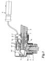
- the Figures 1a, 1b show a side view of a media line 1 with internal heating elements 2, 3.
- the heating elements 2, 3 are led out of the media line 1 at different lengths l 1 , l 2 at the two ends 10, 11.
- the two heating elements 2, 3 can be of approximately the same length, but can only be arranged offset from one another, as shown in Figure 1 is indicated.
- the length difference of the protruding heating element length ⁇ l depends on the winding length required for wrapping a line connector, as in the Figures 3 and 4 shown, chosen.
- the protruding length of the heating element 2 at the end 10 of the media line is designated l 21 and the protruding length of the heating element 3 at this end 10 of the media line is designated l 31 , the difference in length, as already mentioned, is designated ⁇ l 1 . Since the two heating elements 2, 3 according to the embodiment in Figure 1a are approximately the same length, there is a corresponding length difference ⁇ l 1 'at the other end 11 of the media line, with ⁇ l 1 equal to ⁇ l 1 ', with the heating element 3 protruding there with a greater length l 31 'than the heating element 2, which also a length l 21 'protrudes there, where l 21 can be equal to I 31 ' and l 31 can be equal to I 21 '.
- the two heating elements 2, 3 have different lengths, with the heating element 2 being significantly longer than the heating element 3. Accordingly, the heating element 2 protrudes further from the media line at both the end 10 and the end 11 of the media line than the heating element 3.
- the length difference ⁇ l 1 at one end 10 of the media line can be equal to the length difference ⁇ l 1 'at the other End 11 of the media line, but can also be different from this. The latter case is in Figure 1b indicated.
- a corrugated pipe 6 is placed on the media line to the outside Protection and insulation as well as a corrugated pipe seal and, for example, a crimp ring are applied or pushed on.
- the corrugated pipe seal is inserted between the media line 1 and the corrugated pipe 6 and in particular has an external shape that is adapted to the shape of the corrugated pipe, so it can engage from the inside in the wave crests and troughs of the corrugated pipe in order to enable a seal.
- the crimp ring can be pushed onto corresponding connecting elements of the line connectors 4, 5, such as a mandrel profile, and after this mandrel, a firm connection can be created between the media line and the line connectors by squeezing the crimp ring.
- a force of 1,500 to 2,000 N, in particular 1,800 N can be applied to the outside of such a crimp ring in order to create a firm connection between the media line and the line connector.
- the crimp connection can be protected from the outside by applying an adhesive or fabric or fabric tape.
- the transition from this connection point to the corrugated pipe 6 provided with the corrugated pipe seal can also take place, for example, using an adhesive tape, fabric tape or fabric tape.
- the two heating elements 2, 3 can be sealed in the line connectors 4, 5. This can be done by providing or pushing individual sealing elements onto the heating elements or by providing a double seal, which is also pushed onto the heating elements. With a double seal, both heating elements are passed through a sealing element and sealed against it in an opening in the line connector. All that is needed is to insert this one sealing element into the opening provided in the line connector 4 or 5. This is not shown in the figures.
- the heating elements After inserting the sealing element(s) into the line connectors 4, 5, the heating elements can be cut to length and the insulation stripped at the ends. This sets the heating power required for heating the medium flowing through the line connectors of the heating element provided for wrapping the line connectors 4, 5.
- the cutting is hence a calibration cut.
- the remaining sections 22, 32 of the two heating elements 2, 3 have a length l 21 "or l 31 ", respectively Figure 2 can be removed.
- the line connector 4 can be wrapped with the section 22 of the heating element 2, the line connector 5 with the section 33 of the heating element 3.
- the sections 32 and 23 are not used to heat the line connectors 4 and 5, respectively.
- Very thin heating elements are usually used for the internal heating of the media line 1, which is advantageously taken into account when connecting to the two PTC conductors 7, 8. If there is not enough material available for a secure connection, a filler element can be inserted in the area of the connection point.
- the PTC thermistor leads, as in Figure 3 shown, to an electrical plug 9 to enable an electrical connection of the heating elements 2, 3.
- the protruding section of the heating elements which protrudes from the media line or I 21 " from the line connector 4 or 5 with a length l 21 ", can be wound around it .
- the heating element 2 therefore serves to heat the angled line connector 4, whereas the heating element 3 here does not contribute to heating the line connector 4, or at least only contributes very slightly.
- the line connector 4 is partially encased in an encapsulation 45.
- the encapsulation 45 has at least one receptacle 46 for receiving the line connector and one or two Recordings 47 for receiving the crimp connections or connection points 70, 80 of heating elements and PTC conductors. After wrapping the line connector 4 with the heating element 2, the connection points 70, 80 are inserted into the corresponding receptacle or receptacles 47 of the encapsulation 45 and the two PTC thermistor 7, 8 are led out of the encapsulation 45, whereby these open into the electrical plug 9 already mentioned .
- the encapsulation 45 is advantageously constructed with two or more shells, so that assembly and routing of the lines is possible without any problems.
- one of the shell parts of the encapsulation designed here as a housing can first be arranged to at least partially surround the line connector 4, all the lines to be led out can be led out of the housing, and only then can the other shell part (s) be joined to cover the first shell part.
- shrink tubing or overmolding may also be provided to provide mechanical protection.
- the heating power requirement inside the line connector can be, for example, 0.4 to 0.8 W, in particular 0.6 W.
- Heating elements, such as strands, with a heating output of 7 W/m can be used, corresponding to 8 to 20 W/m, in particular 14 W/m, if two strands are provided. This heating output is achieved in the area of the media line, which is arranged between the two line connectors 4, 5.
- the heating power requirement can also be 0.4 to 0.8 W, in particular 0.6 W.
- the heating power requirements of the angled and straight line connectors therefore correspond to each other.
- Different heating outputs can also be achieved depending on the application.
- the two heating elements 2, 3 can already be designed differently, i.e. have a different heating resistance in order to achieve different heating outputs, so that a line connector wrapped with the heating element 2 can be heated at a different temperature than one with the heating element 3 wrapped line connector.
- a change in the heating output can also be achieved by maintaining the outer diameter and changing the insulation.
- the heating power requirement on the outside of the line connector can be 0.6 to 1 W, in particular 0.8 W, for both the angled and the straight line connector, i.e. taking the inside and outside into account as a whole, 1 to 1.8 W, in particular 1.4 W.
- the ratio of the heating power on the inside and outside of the line connector is therefore 0.65 to 0.8, in particular 0.75, for both line connectors.
- the strand length on the inside of the line connector can be 20 to 60 mm, in particular 40 mm, per strand.
- the difference in length between the first heating element and the second heating element is, for example, 100 to 150 mm, in particular 120 mm.
- the length ratio of the heating element length sum to the length difference is accordingly in particular 2:3.
- the line connector can therefore be heated in particular with a heating output of 0.6 W.
- the line connector 4 has at least two hook-shaped holding elements 41 on its top side 40.
- the heating elements 2, 3 can be fixed in place on the line connector using an adhesive, fabric or fabric adhesive tape, particularly in the area of the mandrel point 42 of the media line. This is in Figure 3 however not shown.
- the two heating elements 2, 3 are connected directly to one another, for example by crimping.
- the PTC thermistor 7, 8 are attached to the respective opposite ends of the heating elements 2, 3, as is the case Figure 6 can be removed.
- One heating element can be made longer than the other, as shown in Figure 6 can also be seen, wherein in this embodiment the heating element 3 is provided for wrapping around the line connector 4 and the heating element 2 is guided on the top or otherwise outside of the line connector 4 to the crimping point 20.
- the crimping point 20 can, for example, also be arranged in a receptacle 47 of the encapsulation 45 and protected therein against external influences. If the two heating elements have a diameter that is too small, filling elements or devices for increasing the diameter can be added to create an optimal connection or crimping point.
- a filling element can be, for example, a PTC conductor strand.
- a bridge or loop element 100 can be connected to the two heating element ends 21, 31. This is in Figure 5 indicated.
- the bridge element 100 is connected to the two heating elements 2, 3 via two crimping points 20, 30.
- the two PTC thermistor 7, 8 are connected to the two heating elements 2, 3 via the connection or crimping points 70, 80.
- the longer of the two heating elements 2, 3 can again be arranged in a coiled manner on the outside of the line connector.
- the shorter heating element or the shorter section of the other heating element is arranged on its outer or upper side 40 essentially without exerting a heating effect on the line connector or the medium flowing therein.
- the crimping points 20, 30 can be inserted into the receptacle or receptacles 47 in the encapsulation 45, but this is not the case Figure 5 is not shown.
- the bridge or loop element 100 that is not inserted into the receptacle 47 is, insofar as it protrudes beyond the outer extent of the encapsulation 45, fixed, for example, on the outside of the cladding, in particular corrugated, tube 6, in particular by means of an adhesive, fabric or fabric adhesive tape .
- a series connection of the two heating elements 2, 3 as well as a parallel connection can be created, with the bridge element being either completely removed for a parallel connection, i.e the ends of the heating elements 2, 3 remain open, or the bridge element is only detached from the respective heating element on one side for a series connection.
- Figure 4 shows a side view of a further embodiment of a prefabricated media line according to the invention, comprising the two line connectors 4, 5 and the media line 1 provided with internal heating elements 2,3 with a sheathing corrugated tube 6.
- the respective ends 21, 31 of the two heating elements 2, 3 are provided with the bridge or loop element 100.
- the heating element 2,3, as shown as a schematic sketch in Figure 5 is shown in the embodiment according to Figure 4 used.
- the heating element 3 is coiled around it, whereas the heating element 2 is guided directly to the crimping point 20.
- the two crimping points 20, 30 can be accommodated in a respective receptacle 47 in the encapsulation 45.
- the straight line connector 5 is also partially wrapped with one of the two heating elements, namely the heating element 2, whereby here too the heating element 2 is not used to wrap around the line connector 5, but is connected directly to a thermistor, namely the thermistor 8, which is only partially shown , in particular crimped.
- the respective connection or crimping points 70, 80 are in Figure 4 also to be seen. These can be accommodated in receptacles 50 in the encapsulation 55, the line connector 5 in a receptacle 51.
- a connection to an electrical plug, as in the embodiment according to Figure 3 shown is also possible here with regard to the PTC thermistor 7, 8.
- the media line 1 according to Figure 4 is designed as an oval, expandable tube, like the one in Figure 4
- the cross section of the media line is also shown.
- the oval shape is chosen to avoid strong pressure acting on the wall of the media line when the volume of the medium within the media line changes due to freezing.
- the oval profile experiences a greater change in shape instead of a strong increase in pressure, so that the for the Increase in volume of the freezing medium required cross-sectional area is achieved at a much lower pressure compared to the round profile.
- the ends 10, 11 of the media line connected to the two line connectors 4, 5 are expanded round so that they can be attached to the line connectors.
- a hose can also be used, in particular a hose with reinforcing inserts, in particular aramid fibers, provided in the jacket.
- the heating elements can be provided with a coating, for example a nickel coating, to protect against corrosion. Furthermore, an insulation coating made of fluoropolymer or FEP, i.e. perfluoroethylene propylene, which has the lowest risk of permeation with regard to ammonia, can be provided as an outer casing for the heating elements.
- the individual coils of the heating conductors or heating elements are advantageously also coated and have an inner fiber, for example made of aramid, in particular Kevlar® Detex 1580, for example with a diameter of 0.4 mm. Surrounding this inner fiber, two, three or even four wires or individual wires with a respective diameter of, for example, 0.14 to 0.16 mm, can be arranged in a coiled manner.
- the total outside diameter of the heating coil is, for example, 0.6 to 0.8 mm.
- the crimping process is optimally adapted to create a low-resistance connection or crimping point 70, 80 by adapting the crimping process to the respective wire thickness. By providing heating coils of the heating conductors or heating elements, high resistances can be generated to optimize the heating output.
- the line connector In addition to a thermal conductivity of the line connector, it can be in the hot area of the assembled heatable media line, i.e. in the area in which it is arranged near devices that emit a lot of heat, such as an exhaust system or an engine, in contrast to the cold area, which itself has little or does not give off heat, so heating is not possible If this area of the assembled media line is required, special temperature resistance is also important.
- a material that is more temperature-resistant than the material used for the line connector in the cold area can be used for the line connector arranged in the hot area, for example a temperature-resistant polymer such as PPA (polyphthalamide). It proves to be further advantageous if the media line in the hot area is also made of a more temperature-resistant material.
- the provision of a two-part line is suitable here.
- the one line connector or quick connector in the hot area and the part of the media line there can therefore be made of PPA, for example, and the remaining media line arranged in the cold area, as well as the line connector there, which can be designed as a plug connector, can be made of a less temperature-resistant material, such as Polyamide 12.
- the line connector can also be made of PA12 GF30, for example, a polyamide 12 with 30% by weight of glass fiber, or a polyamide 6. If a tubular media line is used, this can be made of EPDM (ethylene propylene diene monomer) in the hot area. in combination with a line connector made of PPA.
- the part of the media line made of a temperature-resistant material such as PPA can, for example, be wrapped in a fabric tape and housed in a cladding or corrugated tube made of temperature-resistant TPC (thermoplastic polyester elastomer).
- a crimp connection in the hot area consists of alloy K-75 and a shrink tube made of FEP (perfluoroethylene propylene).
- the remaining media line (in the cold area) made of PA 12 can be wrapped with standard tape and surrounded by a sheath or corrugated pipe made of modified polypropylene.
- the crimp connection in this cold area can be made of CuZn30 and a shrink tube made of XPE (radiation cross-linked polyethylene).
- PPA is particularly suitable for higher temperatures and has very good permeation behavior, meaning it is hardly permeable even to aggressive media flowing through the heatable prefabricated media line.
- FIG 7 a further embodiment of the media line 1 and the line connector 4 attached to it is shown in the form of an angle connector.
- the media line 1 here comprises two media lines arranged one inside the other, an inner media line 1a and an outer media line 1b.
- the inner media line 1a has the two heating elements 2, 3 in its inner lumen 101 and can therefore be heated internally. Medium to be heated can flow through the gap 102 between the inner media line 1a and the outer media line 1b.
- the outer media line 1b is joined to the line connector 4.
- the inner media line 1a is led out through an opening 48 in the wall 49 of the line connector 4.
- a closure element 140 is arranged there on the outside 149 of the wall 49.
- the cladding or corrugated tube 6 is arranged on the outside, leaving the insulating air gap 60 between the outer media line 1b and the cladding tube 6.
- this and one end of the cladding tube 6 Surrounding the outside insulation or protective cap 45 is provided.
- the two heating elements 2, 3 guided through the inner media line 1a are led out of it at the ends.
- the heating element 2 or 3 which is shorter than the outside 149 of the wall 49, is connected to the PTC thermistor 8 at a connection point 80, for example by a crimp connection.
- the connection can be sealed using a shrink tube or potting.
- the heating element 2, 3, which protrudes further beyond the outside 149 of the wall 49, is first wound around the angled connecting piece 43 on the outside and subsequently led to a connection point 70 for connecting to the PTC thermistor 7.
- This connection can also be a crimp connection, which is additionally sealed to the outside by a shrink tube and/or a potting material.
- connection points 70, 80 are arranged within the protective cap 45, in particular in the receptacle 47 provided for this purpose. Both thermistor 7, 8 are opposite the connection points 70, 80 Ends 71, 81 provided with the plug 9, which is used for connection to an electrical power supply.
Landscapes
- Engineering & Computer Science (AREA)
- General Engineering & Computer Science (AREA)
- Mechanical Engineering (AREA)
- Physics & Mathematics (AREA)
- Thermal Sciences (AREA)
- Chemical & Material Sciences (AREA)
- Combustion & Propulsion (AREA)
- Resistance Heating (AREA)
- Pipe Accessories (AREA)
Claims (15)
- Procédé de confection d'une conduite de fluide (1, 1a, 1b) avec des éléments de chauffe intérieurs (2, 3),
caractérisé en ce que- les éléments de chauffe (2, 3) sont intégrés dans la conduite de fluide (1, 1a),- la conduite de fluide (1, 1a, 1b) est montée au niveau d'un connecteur de conduite (4, 5),- au moins un élément étanche est enfilé pour rendre étanche leséléments de chauffe (2, 3) par rapport au connecteur de conduite (4, 5) sur celle-ci et est monté au niveau du connecteur de conduite (4, 5),- lors de la prévoyance d'éléments de chauffe (2, 3) de même longueur ceux-ci sont positionnés à l'extrémité (10, 11) de la conduite de fluide (1, 1a, 1b) de sorte que respectivement un des éléments de chauffe (2, 3) dépasse plus de la conduite de fluide que le au moins un autre ou un des éléments de chauffe (2, 3) n'est coupé à une longueur plus grande (l21, l21', l31, l31') que le ou les autre(s),- respectivement seul un des éléments de chauffe (2, 3) est enroulé ou agencé autour d'un connecteur de conduite (4, 5) sur le côté extérieur au moins partiellement, et- les éléments de chauffe (2, 3) sont laissés ouverts ou reliés électriquement entre eux et/ou à des résistances CTP (7, 8) et/ou à un élément de pont (100) et/ou un élément de remplissage ou sont montés parallèlement. - Procédé selon la revendication 1,
caractérisé en ce que
les éléments de chauffe (2, 3) sont fixés en position par au moins un élément de retenue (41) au niveau du connecteur de conduite (4, 5), en particulier par des éléments de retenue (41) en forme de crochet et/ou une bande de fixation, en particulier un ruban adhésif ou tissé ou adhésif tissé. - Procédé selon la revendication 1 ou 2,
caractérisé en ce que
le connecteur de conduite (4, 5) est reçu au moins partiellement dans un premier logement (46) d'un encapsulage (45) pour l'isolation thermique et/ou pour la protection mécanique et/ou chimique. - Conduite de fluide confectionnée avec une conduite de fluide (1, 1a, 1b) avec des éléments de chauffe intérieurs (2, 3), dans laquelle les éléments de chauffe (2,3)sont intégrés dans la conduite de fluide (1, 1a), et avec au moins un connecteur de conduite (4, 5),
caractérisée en ce que
pour le chauffage du connecteur de conduite (4, 5) seul un des éléments de chauffe (2, 3) situés à l'intérieur et sortant de la conduite de fluide (1, 1a) et du connecteur de conduite (4, 5) est agencé en entourant au moins partiellement le connecteur de conduite (4, 5) sur le côté extérieur de celui-ci. - Conduite de fluide confectionnée selon la revendication 4,
caractérisée en ce que
les sections (22, 32, 23, 33) des éléments de chauffe (2, 3) qui dépassent de la surface d'extrémité du connecteur de conduite (4, 5), présentent une longueur différente (l21", l31"). - Conduite de fluide confectionnée selon la revendication 4,
caractérisée en ce que
les au moins deux éléments de chauffe (2, 3) agencés à l'intérieur de la conduite de fluide (1, 1a, 1b) présentent une longueur différente. - Conduite de fluide confectionnée selon la revendication 4, 5 ou 6,
caractérisée en ce que
les extrémités (21, 31) des éléments de chauffe (2, 3) sont reliées électriquement aux résistances PCT et/ou renforcées par au moins un élément de remplissage et sont reliées électriquement aux résistances CTP (7,8), sont en particulier serties. - Conduite de fluide confectionnée selon l'une des revendications 4 à 7,
caractérisée en ce que
les extrémités (21, 31) des éléments de chauffe (2, 3) sont reliées électriquement entre elles et/ou par au moins un élément de renforcement et reliées électriquement entre elles, en particulier serties. - Conduite de fluide confectionnée selon l'une des revendications 4 à 8,
caractérisée en ce que
les extrémités (21, 31) des éléments de chauffe (2, 3) sont reliées électriquement entre elles et/ou par au moins un élément de pont (100) et/ou par au moins un élément de remplissage et sont reliées électriquement entre elles par au moins un élément de pont, en particulier serties. - Conduite de fluide confectionnée selon l'une des revendications 4 à 9,
caractérisée en ce que
les extrémités (21, 31, 24, 34) des éléments de chauffe (2, 3) et/ou points de liaison ou de sertissage (20, 30, 70, 80) sont reçues dans un encapsulage (45, 55) entourant au moins partiellement le connecteur de conduite (4, 5). - Conduite de fluide confectionnée selon l'une des revendications 5 à 10,
caractérisée en ce que
les éléments de chauffe (2, 3) sont revêtus afin de présenter en particulier un revêtement de protection contre la corrosion sous la forme d'un revêtement métallique, en particulier d'un revêtement de nickel ou d'un étamage, et/ou que les éléments de chauffe (2, 3) présentent une couche d'isolation, en particulier une couche d'isolation de fluoropolymère ou FEP. - Conduite de fluide confectionnée selon l'une des revendications 4 à 11,
caractérisée en ce que
l'élément de chauffe (2, 3) comprend au moins un filament chauffant avec au moins deux brins d'âme de fil de chauffage. - Conduite de fluide confectionnée selon la revendication 12,
caractérisée en ce que
le filament chauffant est revêtu, en particulier présente un revêtement de protection contre la corrosion sous la forme d'un revêtement métallique, en particulier d'un revêtement de nickel ou d'un étamage, et/ou que le filament chauffant présente une couche d'isolation, en particulier une couche d'isolation de fluoropolymère ou de FEP. - Conduite de fluide confectionnée selon l'une des revendications 4 à 13,
caractérisée en ce que
les éléments de chauffe (2, 3) présentent une résistance différente. - Conduite de fluide confectionnée selon l'une des revendications 4 à 14,
caractérisée en ce que
la conduite de fluide comprend au moins deux conduites de fluide (1a, 1b) agencées l'une dans l'autre, dans laquelle une conduite de fluide intérieure (1a) est chauffable à l'intérieur et peut s'écouler ou s'écoule dans un espace intermédiaire (102) entre l'au moins une conduite de fluideintérieure (1a) et une conduite de fluideextérieure (1b).
Applications Claiming Priority (2)
| Application Number | Priority Date | Filing Date | Title |
|---|---|---|---|
| DE102011120356A DE102011120356A1 (de) | 2011-12-07 | 2011-12-07 | Konfektionierte Medienleitung und Verfahren zum Konfektionieren einer Medienleitung mit innenliegenden Heizelementen |
| PCT/EP2012/005030 WO2013083274A1 (fr) | 2011-12-07 | 2012-12-06 | Conduite à fluide confectionnée et procédé de confection d'une conduite à fluide pourvue d'éléments de chauffe internes |
Publications (3)
| Publication Number | Publication Date |
|---|---|
| EP2788646A1 EP2788646A1 (fr) | 2014-10-15 |
| EP2788646B1 EP2788646B1 (fr) | 2020-04-29 |
| EP2788646B2 true EP2788646B2 (fr) | 2023-12-13 |
Family
ID=47471682
Family Applications (1)
| Application Number | Title | Priority Date | Filing Date |
|---|---|---|---|
| EP12809113.9A Active EP2788646B2 (fr) | 2011-12-07 | 2012-12-06 | Conduite à fluide confectionnée et procédé de confection d'une conduite à fluide pourvue d'éléments de chauffe internes |
Country Status (3)
| Country | Link |
|---|---|
| EP (1) | EP2788646B2 (fr) |
| DE (1) | DE102011120356A1 (fr) |
| WO (1) | WO2013083274A1 (fr) |
Families Citing this family (7)
| Publication number | Priority date | Publication date | Assignee | Title |
|---|---|---|---|---|
| DE102013226629A1 (de) * | 2013-12-19 | 2015-06-25 | Contitech Schlauch Gmbh | Beheizbarer elastomerer Hohlkörper, insbesondere beheizbarer Schlauch |
| DE102014007409A1 (de) | 2014-03-14 | 2015-09-17 | Voss Automotive Gmbh | Leitungsverbindungseinrichtung zum lösbaren Verbinden von Medienleitungen oder zumindest einer Medienleitung und zumindest eines Aggregats |
| DE102014108499A1 (de) * | 2014-06-17 | 2015-12-17 | Norma Germany Gmbh | Beheizbare Fluidleitung |
| DE102014214690A1 (de) * | 2014-07-25 | 2016-01-28 | Contitech Techno-Chemie Gmbh | Beheizbarer Schlauch |
| DE102014214687A1 (de) * | 2014-07-25 | 2016-01-28 | Contitech Techno-Chemie Gmbh | Beheizbarer Schlauch |
| DE102014012272A1 (de) * | 2014-08-22 | 2016-02-25 | Voss Automotive Gmbh | Konfektionierte Medienleitung |
| US20170023163A1 (en) | 2015-07-20 | 2017-01-26 | Norma U.S. Holding Llc | Heated Connector Assembly |
Citations (1)
| Publication number | Priority date | Publication date | Assignee | Title |
|---|---|---|---|---|
| DE202007010502U1 (de) † | 2007-07-26 | 2008-11-27 | Voss Automotive Gmbh | Konfektionierte Medienleitung |
Family Cites Families (19)
| Publication number | Priority date | Publication date | Assignee | Title |
|---|---|---|---|---|
| JPH08320096A (ja) * | 1995-05-26 | 1996-12-03 | Kurita Kogyo:Kk | 保温管システム |
| DE19934346B4 (de) | 1999-07-22 | 2005-10-13 | Rehau Ag + Co. | Vorrichtung zur Befestigung und Abdichtung eines Heizelements in einer Scheibenwaschleitung |
| SE529417C2 (sv) * | 2005-12-22 | 2007-08-07 | Volvo Lastvagnar Ab | Ledningsnät för ett fordon |
| US20080041841A1 (en) | 2006-08-03 | 2008-02-21 | Nissan Diesel Motor Co., Ltd. | Piping with heater and connecting method of the piping |
| ATE533989T1 (de) * | 2007-04-26 | 2011-12-15 | Voss Automotive Gmbh | Leitungsverbinder für medienleitungen |
| JP2008309296A (ja) | 2007-06-18 | 2008-12-25 | Nitta Moore Co | 加熱・保温チューブ |
| JP2009002424A (ja) * | 2007-06-21 | 2009-01-08 | Nitta Moore Co | 加熱・保温管の配管構造 |
| JP4823980B2 (ja) | 2007-07-30 | 2011-11-24 | ニッタ株式会社 | 加熱・保温チューブを有する装置 |
| EP2210034B1 (fr) * | 2007-10-11 | 2013-11-20 | Masterflex SE | Tuyau souple chauffant |
| DE202007018089U1 (de) | 2007-12-21 | 2009-05-07 | Voss Automotive Gmbh | Beheizbare Medienleitung |
| EP2222995B1 (fr) | 2007-12-21 | 2014-12-10 | Voss Automotive GmbH | Raccord pour conduits pour fluides ainsi que conduit confectionné pour fluides présentant au moins un raccord pour conduits de ce type |
| JP5059631B2 (ja) | 2008-01-15 | 2012-10-24 | ニッタ株式会社 | 管継手の加熱・保温カバー |
| DE202008015289U1 (de) | 2008-11-18 | 2010-04-08 | Voss Automotive Gmbh | Leitungsverbinder für Medienleitungen |
| DE102008059751A1 (de) | 2008-12-01 | 2010-06-02 | Voss Automotive Gmbh | Verfahren und Heizsystem zum Beheizen eines Fluid-Leitungssystems insbesondere in einem Kraftfahrzeug |
| DE202009012230U1 (de) | 2009-06-23 | 2010-11-04 | Voss Automotive Gmbh | Elektrisch beheizbare Medienleitung sowie Leitungsverbinder |
| FR2950666B1 (fr) | 2009-09-29 | 2011-11-11 | Hutchinson | Dispositif de chauffage d'une ligne de transfert de fluide |
| CN201546791U (zh) | 2009-11-19 | 2010-08-11 | 北汽福田汽车股份有限公司 | 尿素加热装置 |
| DE102011102151B4 (de) | 2011-05-20 | 2022-05-19 | Norma Germany Gmbh | Fluidleitung |
| WO2013053478A1 (fr) | 2011-10-14 | 2013-04-18 | Voss Automotive Gmbh | Connecteur au moins partiellement chauffable pour une conduite chauffable destinée à un milieu, et conduite destinée à un milieu confectionnée et dotée d'un tel connecteur |
-
2011
- 2011-12-07 DE DE102011120356A patent/DE102011120356A1/de active Pending
-
2012
- 2012-12-06 EP EP12809113.9A patent/EP2788646B2/fr active Active
- 2012-12-06 WO PCT/EP2012/005030 patent/WO2013083274A1/fr unknown
Patent Citations (1)
| Publication number | Priority date | Publication date | Assignee | Title |
|---|---|---|---|---|
| DE202007010502U1 (de) † | 2007-07-26 | 2008-11-27 | Voss Automotive Gmbh | Konfektionierte Medienleitung |
Also Published As
| Publication number | Publication date |
|---|---|
| WO2013083274A1 (fr) | 2013-06-13 |
| DE102011120356A1 (de) | 2013-06-13 |
| EP2788646A1 (fr) | 2014-10-15 |
| EP2788646B1 (fr) | 2020-04-29 |
Similar Documents
| Publication | Publication Date | Title |
|---|---|---|
| EP2788646B2 (fr) | Conduite à fluide confectionnée et procédé de confection d'une conduite à fluide pourvue d'éléments de chauffe internes | |
| EP2596274B1 (fr) | Conduite chauffable pour fluides et méthode de sa production | |
| EP2788692B1 (fr) | Conduite à fluide confectionnée, sous forme d'une conduite à fluide comportant au moins deux éléments de chauffe placés sur sa face externe, et procédé de production de ladite conduite | |
| EP2699414B1 (fr) | Conduite de milieux multicouche pouvant être chauffée électriquement | |
| EP2596275B1 (fr) | Conduite chauffable pour fluides | |
| EP2766652B1 (fr) | Conduite de fluide pouvant être chauffée comprenant au moins une conduite de fluide présentant deux raccords de conduite | |
| EP2641006A2 (fr) | Conduite de fluides confectionnée à chauffage électrique et procédé de fabrication de ladite conduite | |
| EP2766651B1 (fr) | Conduite confectionnée comprenant au moins une conduite chauffable et au moins un connecteur au moins partiellement chauffable | |
| WO2008131993A1 (fr) | Raccord pour conduites d'acheminement de substances | |
| WO2014111246A1 (fr) | Conduite de fluide aménagée pouvant être chauffée, utilisation d'une telle conduite et procédé de fabrication d'une telle conduite | |
| DE102012002411A1 (de) | Beheizbare Medienleitung | |
| EP3092433B1 (fr) | Conduite de fluide chauffante surmoulée et procédé de fabrication de cette dernière | |
| EP1764541A1 (fr) | Dispositif de chauffage électrique, tuyau chauffable et son procédé de fabrication | |
| EP1125810A1 (fr) | Conduite chauffée pour installation de freinage hydraulique | |
| EP3436732B1 (fr) | Conduite de fluide chauffante assemblée | |
| EP3234434B1 (fr) | Conduite de fluide chauffante et procédé pour fabriquer une conduite de fluide chauffante | |
| EP3612759A1 (fr) | Ensemble de conduits | |
| WO2013026560A1 (fr) | Tuyau flexible et son procédé de fabrication | |
| DE102013011448A1 (de) | Heizleitung für eine beheizbare Fluid-Leitung | |
| DE102014200874A1 (de) | Verfahren und Anlage zur herstellung eines konfektionierten Kabels vorbestimmter Länge sowie hierfür geeignetes Kontaktbauteil |
Legal Events
| Date | Code | Title | Description |
|---|---|---|---|
| PUAI | Public reference made under article 153(3) epc to a published international application that has entered the european phase |
Free format text: ORIGINAL CODE: 0009012 |
|
| 17P | Request for examination filed |
Effective date: 20140604 |
|
| AK | Designated contracting states |
Kind code of ref document: A1 Designated state(s): AL AT BE BG CH CY CZ DE DK EE ES FI FR GB GR HR HU IE IS IT LI LT LU LV MC MK MT NL NO PL PT RO RS SE SI SK SM TR |
|
| RIN1 | Information on inventor provided before grant (corrected) |
Inventor name: ETSCHEID, TOBIAS Inventor name: SCHWARZKOPF, OTFRIED Inventor name: ISENBURG, MARCO |
|
| DAX | Request for extension of the european patent (deleted) | ||
| GRAP | Despatch of communication of intention to grant a patent |
Free format text: ORIGINAL CODE: EPIDOSNIGR1 |
|
| RIC1 | Information provided on ipc code assigned before grant |
Ipc: F24H 1/10 20060101ALI20190625BHEP Ipc: F16L 25/01 20060101AFI20190625BHEP Ipc: H05B 3/58 20060101ALI20190625BHEP Ipc: F16L 53/38 20180101ALI20190625BHEP Ipc: F16L 53/00 20180101ALI20190625BHEP Ipc: F01N 3/20 20060101ALI20190625BHEP Ipc: F24H 1/00 20060101ALI20190625BHEP |
|
| STAA | Information on the status of an ep patent application or granted ep patent |
Free format text: STATUS: GRANT OF PATENT IS INTENDED |
|
| INTG | Intention to grant announced |
Effective date: 20190801 |
|
| GRAS | Grant fee paid |
Free format text: ORIGINAL CODE: EPIDOSNIGR3 |
|
| GRAJ | Information related to disapproval of communication of intention to grant by the applicant or resumption of examination proceedings by the epo deleted |
Free format text: ORIGINAL CODE: EPIDOSDIGR1 |
|
| GRAL | Information related to payment of fee for publishing/printing deleted |
Free format text: ORIGINAL CODE: EPIDOSDIGR3 |
|
| STAA | Information on the status of an ep patent application or granted ep patent |
Free format text: STATUS: REQUEST FOR EXAMINATION WAS MADE |
|
| GRAP | Despatch of communication of intention to grant a patent |
Free format text: ORIGINAL CODE: EPIDOSNIGR1 |
|
| STAA | Information on the status of an ep patent application or granted ep patent |
Free format text: STATUS: GRANT OF PATENT IS INTENDED |
|
| INTC | Intention to grant announced (deleted) | ||
| INTG | Intention to grant announced |
Effective date: 20200107 |
|
| GRAA | (expected) grant |
Free format text: ORIGINAL CODE: 0009210 |
|
| STAA | Information on the status of an ep patent application or granted ep patent |
Free format text: STATUS: THE PATENT HAS BEEN GRANTED |
|
| AK | Designated contracting states |
Kind code of ref document: B1 Designated state(s): AL AT BE BG CH CY CZ DE DK EE ES FI FR GB GR HR HU IE IS IT LI LT LU LV MC MK MT NL NO PL PT RO RS SE SI SK SM TR |
|
| REG | Reference to a national code |
Ref country code: GB Ref legal event code: FG4D Free format text: NOT ENGLISH |
|
| REG | Reference to a national code |
Ref country code: CH Ref legal event code: EP |
|
| REG | Reference to a national code |
Ref country code: DE Ref legal event code: R096 Ref document number: 502012016032 Country of ref document: DE |
|
| REG | Reference to a national code |
Ref country code: AT Ref legal event code: REF Ref document number: 1263836 Country of ref document: AT Kind code of ref document: T Effective date: 20200515 |
|
| REG | Reference to a national code |
Ref country code: IE Ref legal event code: FG4D Free format text: LANGUAGE OF EP DOCUMENT: GERMAN |
|
| REG | Reference to a national code |
Ref country code: NL Ref legal event code: MP Effective date: 20200429 |
|
| REG | Reference to a national code |
Ref country code: LT Ref legal event code: MG4D |
|
| PG25 | Lapsed in a contracting state [announced via postgrant information from national office to epo] |
Ref country code: LT Free format text: LAPSE BECAUSE OF FAILURE TO SUBMIT A TRANSLATION OF THE DESCRIPTION OR TO PAY THE FEE WITHIN THE PRESCRIBED TIME-LIMIT Effective date: 20200429 Ref country code: PT Free format text: LAPSE BECAUSE OF FAILURE TO SUBMIT A TRANSLATION OF THE DESCRIPTION OR TO PAY THE FEE WITHIN THE PRESCRIBED TIME-LIMIT Effective date: 20200831 Ref country code: IS Free format text: LAPSE BECAUSE OF FAILURE TO SUBMIT A TRANSLATION OF THE DESCRIPTION OR TO PAY THE FEE WITHIN THE PRESCRIBED TIME-LIMIT Effective date: 20200829 Ref country code: NO Free format text: LAPSE BECAUSE OF FAILURE TO SUBMIT A TRANSLATION OF THE DESCRIPTION OR TO PAY THE FEE WITHIN THE PRESCRIBED TIME-LIMIT Effective date: 20200729 Ref country code: FI Free format text: LAPSE BECAUSE OF FAILURE TO SUBMIT A TRANSLATION OF THE DESCRIPTION OR TO PAY THE FEE WITHIN THE PRESCRIBED TIME-LIMIT Effective date: 20200429 Ref country code: GR Free format text: LAPSE BECAUSE OF FAILURE TO SUBMIT A TRANSLATION OF THE DESCRIPTION OR TO PAY THE FEE WITHIN THE PRESCRIBED TIME-LIMIT Effective date: 20200730 Ref country code: SE Free format text: LAPSE BECAUSE OF FAILURE TO SUBMIT A TRANSLATION OF THE DESCRIPTION OR TO PAY THE FEE WITHIN THE PRESCRIBED TIME-LIMIT Effective date: 20200429 |
|
| PG25 | Lapsed in a contracting state [announced via postgrant information from national office to epo] |
Ref country code: HR Free format text: LAPSE BECAUSE OF FAILURE TO SUBMIT A TRANSLATION OF THE DESCRIPTION OR TO PAY THE FEE WITHIN THE PRESCRIBED TIME-LIMIT Effective date: 20200429 Ref country code: LV Free format text: LAPSE BECAUSE OF FAILURE TO SUBMIT A TRANSLATION OF THE DESCRIPTION OR TO PAY THE FEE WITHIN THE PRESCRIBED TIME-LIMIT Effective date: 20200429 Ref country code: BG Free format text: LAPSE BECAUSE OF FAILURE TO SUBMIT A TRANSLATION OF THE DESCRIPTION OR TO PAY THE FEE WITHIN THE PRESCRIBED TIME-LIMIT Effective date: 20200729 Ref country code: RS Free format text: LAPSE BECAUSE OF FAILURE TO SUBMIT A TRANSLATION OF THE DESCRIPTION OR TO PAY THE FEE WITHIN THE PRESCRIBED TIME-LIMIT Effective date: 20200429 |
|
| PG25 | Lapsed in a contracting state [announced via postgrant information from national office to epo] |
Ref country code: AL Free format text: LAPSE BECAUSE OF FAILURE TO SUBMIT A TRANSLATION OF THE DESCRIPTION OR TO PAY THE FEE WITHIN THE PRESCRIBED TIME-LIMIT Effective date: 20200429 Ref country code: NL Free format text: LAPSE BECAUSE OF FAILURE TO SUBMIT A TRANSLATION OF THE DESCRIPTION OR TO PAY THE FEE WITHIN THE PRESCRIBED TIME-LIMIT Effective date: 20200429 |
|
| PG25 | Lapsed in a contracting state [announced via postgrant information from national office to epo] |
Ref country code: ES Free format text: LAPSE BECAUSE OF FAILURE TO SUBMIT A TRANSLATION OF THE DESCRIPTION OR TO PAY THE FEE WITHIN THE PRESCRIBED TIME-LIMIT Effective date: 20200429 Ref country code: EE Free format text: LAPSE BECAUSE OF FAILURE TO SUBMIT A TRANSLATION OF THE DESCRIPTION OR TO PAY THE FEE WITHIN THE PRESCRIBED TIME-LIMIT Effective date: 20200429 Ref country code: IT Free format text: LAPSE BECAUSE OF FAILURE TO SUBMIT A TRANSLATION OF THE DESCRIPTION OR TO PAY THE FEE WITHIN THE PRESCRIBED TIME-LIMIT Effective date: 20200429 Ref country code: SM Free format text: LAPSE BECAUSE OF FAILURE TO SUBMIT A TRANSLATION OF THE DESCRIPTION OR TO PAY THE FEE WITHIN THE PRESCRIBED TIME-LIMIT Effective date: 20200429 Ref country code: DK Free format text: LAPSE BECAUSE OF FAILURE TO SUBMIT A TRANSLATION OF THE DESCRIPTION OR TO PAY THE FEE WITHIN THE PRESCRIBED TIME-LIMIT Effective date: 20200429 Ref country code: CZ Free format text: LAPSE BECAUSE OF FAILURE TO SUBMIT A TRANSLATION OF THE DESCRIPTION OR TO PAY THE FEE WITHIN THE PRESCRIBED TIME-LIMIT Effective date: 20200429 Ref country code: RO Free format text: LAPSE BECAUSE OF FAILURE TO SUBMIT A TRANSLATION OF THE DESCRIPTION OR TO PAY THE FEE WITHIN THE PRESCRIBED TIME-LIMIT Effective date: 20200429 |
|
| REG | Reference to a national code |
Ref country code: DE Ref legal event code: R026 Ref document number: 502012016032 Country of ref document: DE |
|
| PLBI | Opposition filed |
Free format text: ORIGINAL CODE: 0009260 |
|
| PLAX | Notice of opposition and request to file observation + time limit sent |
Free format text: ORIGINAL CODE: EPIDOSNOBS2 |
|
| PG25 | Lapsed in a contracting state [announced via postgrant information from national office to epo] |
Ref country code: SK Free format text: LAPSE BECAUSE OF FAILURE TO SUBMIT A TRANSLATION OF THE DESCRIPTION OR TO PAY THE FEE WITHIN THE PRESCRIBED TIME-LIMIT Effective date: 20200429 Ref country code: PL Free format text: LAPSE BECAUSE OF FAILURE TO SUBMIT A TRANSLATION OF THE DESCRIPTION OR TO PAY THE FEE WITHIN THE PRESCRIBED TIME-LIMIT Effective date: 20200429 |
|
| 26 | Opposition filed |
Opponent name: TI AUTOMOTIVE (FULDABRUECK) GMBH Effective date: 20210129 |
|
| PG25 | Lapsed in a contracting state [announced via postgrant information from national office to epo] |
Ref country code: SI Free format text: LAPSE BECAUSE OF FAILURE TO SUBMIT A TRANSLATION OF THE DESCRIPTION OR TO PAY THE FEE WITHIN THE PRESCRIBED TIME-LIMIT Effective date: 20200429 |
|
| PLBB | Reply of patent proprietor to notice(s) of opposition received |
Free format text: ORIGINAL CODE: EPIDOSNOBS3 |
|
| REG | Reference to a national code |
Ref country code: CH Ref legal event code: PL |
|
| GBPC | Gb: european patent ceased through non-payment of renewal fee |
Effective date: 20201206 |
|
| PG25 | Lapsed in a contracting state [announced via postgrant information from national office to epo] |
Ref country code: MC Free format text: LAPSE BECAUSE OF FAILURE TO SUBMIT A TRANSLATION OF THE DESCRIPTION OR TO PAY THE FEE WITHIN THE PRESCRIBED TIME-LIMIT Effective date: 20200429 |
|
| REG | Reference to a national code |
Ref country code: BE Ref legal event code: MM Effective date: 20201231 |
|
| PG25 | Lapsed in a contracting state [announced via postgrant information from national office to epo] |
Ref country code: IE Free format text: LAPSE BECAUSE OF NON-PAYMENT OF DUE FEES Effective date: 20201206 Ref country code: LU Free format text: LAPSE BECAUSE OF NON-PAYMENT OF DUE FEES Effective date: 20201206 |
|
| PG25 | Lapsed in a contracting state [announced via postgrant information from national office to epo] |
Ref country code: CH Free format text: LAPSE BECAUSE OF NON-PAYMENT OF DUE FEES Effective date: 20201231 Ref country code: GB Free format text: LAPSE BECAUSE OF NON-PAYMENT OF DUE FEES Effective date: 20201206 Ref country code: LI Free format text: LAPSE BECAUSE OF NON-PAYMENT OF DUE FEES Effective date: 20201231 |
|
| REG | Reference to a national code |
Ref country code: AT Ref legal event code: MM01 Ref document number: 1263836 Country of ref document: AT Kind code of ref document: T Effective date: 20201206 |
|
| PG25 | Lapsed in a contracting state [announced via postgrant information from national office to epo] |
Ref country code: AT Free format text: LAPSE BECAUSE OF NON-PAYMENT OF DUE FEES Effective date: 20201206 |
|
| PG25 | Lapsed in a contracting state [announced via postgrant information from national office to epo] |
Ref country code: TR Free format text: LAPSE BECAUSE OF FAILURE TO SUBMIT A TRANSLATION OF THE DESCRIPTION OR TO PAY THE FEE WITHIN THE PRESCRIBED TIME-LIMIT Effective date: 20200429 Ref country code: MT Free format text: LAPSE BECAUSE OF FAILURE TO SUBMIT A TRANSLATION OF THE DESCRIPTION OR TO PAY THE FEE WITHIN THE PRESCRIBED TIME-LIMIT Effective date: 20200429 Ref country code: CY Free format text: LAPSE BECAUSE OF FAILURE TO SUBMIT A TRANSLATION OF THE DESCRIPTION OR TO PAY THE FEE WITHIN THE PRESCRIBED TIME-LIMIT Effective date: 20200429 |
|
| PG25 | Lapsed in a contracting state [announced via postgrant information from national office to epo] |
Ref country code: MK Free format text: LAPSE BECAUSE OF FAILURE TO SUBMIT A TRANSLATION OF THE DESCRIPTION OR TO PAY THE FEE WITHIN THE PRESCRIBED TIME-LIMIT Effective date: 20200429 |
|
| PG25 | Lapsed in a contracting state [announced via postgrant information from national office to epo] |
Ref country code: BE Free format text: LAPSE BECAUSE OF NON-PAYMENT OF DUE FEES Effective date: 20201231 |
|
| PLBP | Opposition withdrawn |
Free format text: ORIGINAL CODE: 0009264 |
|
| P01 | Opt-out of the competence of the unified patent court (upc) registered |
Effective date: 20230531 |
|
| PGFP | Annual fee paid to national office [announced via postgrant information from national office to epo] |
Ref country code: FR Payment date: 20230627 Year of fee payment: 12 |
|
| PUAH | Patent maintained in amended form |
Free format text: ORIGINAL CODE: 0009272 |
|
| STAA | Information on the status of an ep patent application or granted ep patent |
Free format text: STATUS: PATENT MAINTAINED AS AMENDED |
|
| 27A | Patent maintained in amended form |
Effective date: 20231213 |
|
| AK | Designated contracting states |
Kind code of ref document: B2 Designated state(s): AL AT BE BG CH CY CZ DE DK EE ES FI FR GB GR HR HU IE IS IT LI LT LU LV MC MK MT NL NO PL PT RO RS SE SI SK SM TR |
|
| REG | Reference to a national code |
Ref country code: DE Ref legal event code: R102 Ref document number: 502012016032 Country of ref document: DE |
|
| PGFP | Annual fee paid to national office [announced via postgrant information from national office to epo] |
Ref country code: DE Payment date: 20231201 Year of fee payment: 12 |