EP2788643B1 - Anordnung zum fluidtransport durch eine rohrleitung und zugehörige schwimmende struktur - Google Patents
Anordnung zum fluidtransport durch eine rohrleitung und zugehörige schwimmende struktur Download PDFInfo
- Publication number
- EP2788643B1 EP2788643B1 EP12810363.7A EP12810363A EP2788643B1 EP 2788643 B1 EP2788643 B1 EP 2788643B1 EP 12810363 A EP12810363 A EP 12810363A EP 2788643 B1 EP2788643 B1 EP 2788643B1
- Authority
- EP
- European Patent Office
- Prior art keywords
- pipe
- section
- ballast
- sections
- downstream
- Prior art date
- Legal status (The legal status is an assumption and is not a legal conclusion. Google has not performed a legal analysis and makes no representation as to the accuracy of the status listed.)
- Active
Links
Images


Classifications
-
- F—MECHANICAL ENGINEERING; LIGHTING; HEATING; WEAPONS; BLASTING
- F16—ENGINEERING ELEMENTS AND UNITS; GENERAL MEASURES FOR PRODUCING AND MAINTAINING EFFECTIVE FUNCTIONING OF MACHINES OR INSTALLATIONS; THERMAL INSULATION IN GENERAL
- F16L—PIPES; JOINTS OR FITTINGS FOR PIPES; SUPPORTS FOR PIPES, CABLES OR PROTECTIVE TUBING; MEANS FOR THERMAL INSULATION IN GENERAL
- F16L1/00—Laying or reclaiming pipes; Repairing or joining pipes on or under water
- F16L1/12—Laying or reclaiming pipes on or under water
- F16L1/20—Accessories therefor, e.g. floats or weights
- F16L1/24—Floats; Weights
-
- F—MECHANICAL ENGINEERING; LIGHTING; HEATING; WEAPONS; BLASTING
- F16—ENGINEERING ELEMENTS AND UNITS; GENERAL MEASURES FOR PRODUCING AND MAINTAINING EFFECTIVE FUNCTIONING OF MACHINES OR INSTALLATIONS; THERMAL INSULATION IN GENERAL
- F16L—PIPES; JOINTS OR FITTINGS FOR PIPES; SUPPORTS FOR PIPES, CABLES OR PROTECTIVE TUBING; MEANS FOR THERMAL INSULATION IN GENERAL
- F16L1/00—Laying or reclaiming pipes; Repairing or joining pipes on or under water
- F16L1/12—Laying or reclaiming pipes on or under water
- F16L1/16—Laying or reclaiming pipes on or under water on the bottom
-
- F—MECHANICAL ENGINEERING; LIGHTING; HEATING; WEAPONS; BLASTING
- F16—ENGINEERING ELEMENTS AND UNITS; GENERAL MEASURES FOR PRODUCING AND MAINTAINING EFFECTIVE FUNCTIONING OF MACHINES OR INSTALLATIONS; THERMAL INSULATION IN GENERAL
- F16L—PIPES; JOINTS OR FITTINGS FOR PIPES; SUPPORTS FOR PIPES, CABLES OR PROTECTIVE TUBING; MEANS FOR THERMAL INSULATION IN GENERAL
- F16L1/00—Laying or reclaiming pipes; Repairing or joining pipes on or under water
- F16L1/12—Laying or reclaiming pipes on or under water
- F16L1/20—Accessories therefor, e.g. floats or weights
- F16L1/202—Accessories therefor, e.g. floats or weights fixed on or to vessels
- F16L1/203—Accessories therefor, e.g. floats or weights fixed on or to vessels the pipes being wound spirally prior to laying
-
- Y—GENERAL TAGGING OF NEW TECHNOLOGICAL DEVELOPMENTS; GENERAL TAGGING OF CROSS-SECTIONAL TECHNOLOGIES SPANNING OVER SEVERAL SECTIONS OF THE IPC; TECHNICAL SUBJECTS COVERED BY FORMER USPC CROSS-REFERENCE ART COLLECTIONS [XRACs] AND DIGESTS
- Y10—TECHNICAL SUBJECTS COVERED BY FORMER USPC
- Y10T—TECHNICAL SUBJECTS COVERED BY FORMER US CLASSIFICATION
- Y10T137/00—Fluid handling
- Y10T137/6851—With casing, support, protector or static constructional installations
- Y10T137/6918—With hose storage or retrieval means
- Y10T137/6954—Reel with support therefor
Definitions
- the invention relates to the underwater installation of a liquid transport pipe, typically fresh water.
- This is in particular an assembly comprising the pipe to be laid and the laying device on a site of such a pipe, typically used to transport fresh water over several hundred (or more) kilometers, this pipe being flexible and having a deformable section.
- Such a transport pipe can be installed on a seabed, to a depth that can be 200 m.
- the pipe may be connected to the coast by a landing structure similar in principle to that described for the first end and connected to a freshwater receiving installation.
- Balancing chimneys located at each end of the pipe, installed on the ground can absorb any pressure jolts ("water hammer”), which could occur during operation.
- Pre-treatment facilities upstream of the shipping pump unit can make the freshwater transportable.
- Treatment facilities located downstream of the receiving facilities make this water clean for its intended use.
- a problem in this context is how to design the pipe and its installation device to make practical, relatively fast and reliable installation, so that the installation allows the pipe to be quickly operational (transport of liquid) once installed.
- a corollary problem concerns how to use the flexible, deformable and therefore foldable nature of the pipe to tend towards a high-performance solution to the problematic above, especially in connection with the connection of these sections.
- the above-mentioned means of presentation comprise means of conformation of the first and second sections of pipe, these means of conformation presenting, upstream and downstream of the assembly means, sections which respectively increase and decrease of the upstream downstream along the longitudinal axis of the laying device, these sections being followed by said first and second pipe sections, when they pass around and along them.
- the shaping means it will be possible, by a flow of the pipe along an internal shaper (hereinafter referred to as "the shaping means") to obtain a spontaneous deformation of the pipe which will conform to the shape of the outer surface of this shaper.
- Another corollary problem concerns how to design the drum and to shape the pipe in order to reach a high-performance solution to the problematic above.
- the winch has a capstan effect and thus includes several motorized rollers (preferably each with a horizontal axis ), each for the transmission of a portion of the axial tension, and around which passes, without complete turn (angle less than 2pi radian), the elongated pipe with its section flattened or immediately close (internal section can be zero or immediately close to zero).
- ballast in particular a means, such a ballast, which, in a volume of fluid, causes or keeps down this volume an element linked to this means.
- the ballast system comprises a weighting envelope, flexible, containing, without mixing with the liquid to be transported, a material weighing with a density greater than that of the seawater, the assembly, immersed in a fluid having non-uniform motions. stationary, thus tending to rest on the bottom (80) of the immersion zone.
- a granular material will be convenient to use and easy to find and transport.
- ballasting system is provided with a ballast and that the attachment means comprise a flexible connection.
- ballast means for providing a granular material, as ballast. It is then advised that these supply means (which will descend into the immersion fluid) have a discharge opening of the granular material, towards the bottom, or at the bottom, of the fluid where the pipe is immersed, in and in contact with the ballast envelope.
- a floating structure comprising the device then disposed on a bridge of this structure.
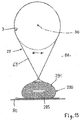
- FIG. 1 in particular, we see a floating structure 1 comprising a device 10 for laying on a site 11 of an elongated liquid transport pipe 3 disposed on a bridge 13 of the floating structure 1.
- the laying device 10 makes it possible to lay on the seabed (several hundred meters away from the coast, for example between two regions of the world) a liquid transport pipe, a priori fresh water intended to be drunk (after purification treatment, if only for maximum food safety).
- the pipe 3 has a longitudinal axis 30.
- This pipe is flexible, with a deformable section between a circular inner section ( figure 7b internal diameter d1) and a flattened internal section which may be zero. It is also foldable on itself longitudinally. At the folds, a radius of curvature of less than 10% (and preferably 5%) of the diameter of its circular internal section may be provided.
- first supply vessel 111a (or any equivalent floating structure) along the first edge 33a, to hoist on board the third pipe section 3c. then wrapped around the additional drum 150 provided by the first supply vessel 111, while on the opposite edge 33b can then, or previously, overflow (possibly on board a second supply vessel 111b), the empty drum 15 to evacuate, all via the crane 31 (see figure 4 ).
- the drum 15, like the others after him, may, for example via slides, be mounted on rails 35 oriented (or directional) across the axis 10a.
- the drum 15 will be movable on the rails 35 and removable vis-à-vis thereof.
- Releasable means 37 for fixing for example with releasable hooks, may allow this.
- this pipe could, however, then be in a state immediately close to such a flat state, that is to say ovalized.
- the pipe structure could make it difficult or even inadvisable, such a completely flat crushing of the pipe.
- this pipe will favorably consist of a continuous woven material tube of synthetic threads.
- the second possibility is that the drum has a width 12, oriented as above, but which will then be less than the half-perimeter ⁇ .d1 / 2.
- the (relevant section of) pipe will in this case be wound flat (or in the said state immediately close), folded on itself, around the drum.
- Figure 7a the third section 190a3 passes (upstream, AM) a circular or elliptical section of low eccentricity, with an outer perimeter slightly smaller than the inner perimeter ( ⁇ .d1) of the pipe ( figure 7b ), further downstream (AV), an oval-shaped section very elongated horizontally ( figure 7d ), with a large width L1 again slightly lower than the inner perimeter ( ⁇ .d1) of the pipe which, as above substantially elastically complies with this shape which is imposed on it,
- the first section 190a0 passes (upstream, AM) of the oval shaped section very elongated horizontally ( figure 7d ), with a large width L1 to, at its downstream end (AV), said circular section or elliptical with low eccentricity, with its outer perimeter slightly lower than the inner perimeter ( ⁇ .d1) of the pipe ( figure 7b ).
- the figure 7e shows an intermediate state of the section, therefore of the pipe, the evolution of section being favorably continuous.
- Figures 3 , 9 we see more exactly a preferred conformation of the second intermediate sections, 1900a0, 1900b0 elements 190a, 190b.
- These intermediate sections each comprise an upstream portion 190a1, 190b1 and a downstream portion 190a2, 190b2 respectively positioned, at the time of a butting, facing the first and second pipe sections 3a, 3b (see FIG. figure 8 ).
- At least one of these first and second elements will preferably comprise first and second drive means for driving the first or second pipe section 3a, 3b along the longitudinal axis 30.
- these first and second drive means each comprise an upstream portion 191a1, 191b1 and a downstream portion 190a2, 190b2, respectively positioned during a butt joint facing the first and second pipe sections 3a, 3b (see FIG. figure 8 ).
- each of these upstream portions 191a1, 191b1 and downstream 190a2,190b2 will be provided with adjustable support and spacing means 195, such as hydraulic cylinders which adjust the radial position of the first and second drive means , so as to clamp the wall of the pipe 3 between the pads, to the desired radius; cf. figure 8 .
- adjustable support and spacing means 195 such as hydraulic cylinders which adjust the radial position of the first and second drive means , so as to clamp the wall of the pipe 3 between the pads, to the desired radius; cf. figure 8 .
- the upstream portion of these first and / or second drive means 191a1, 191b1 is adapted to drive temporarily, downstream (AV) the first pipe section 3a along said longitudinal axis 30, a predetermined distance, to the second pipe section 3b in place between the downstream portion 190a2,190b2, and whose free end is positioned opposite the abutting means 22.
- AV downstream
- the downstream part (191a2, 191b2) means aforesaid, translate upstream the second pipe section 3b to the first. This would cause a tension on the pipe section already laid that could be compensated by a decline in the laying structure.
- said upstream and downstream portions (191a1, 191b1, 191a2, 191b2) of the aforementioned means are arranged to act along the axis 10a / 30, with a priori an ability to move closer and away in pairs (191a1 with 191b1 and 191a2 with 191b2), transversely to the aforementioned axis, so as to be active (with if necessary a variable pressure on the pipe) or inactive at the desired moments (see below) screw pipe sections / disposed (s) ) opposite.
- downstream axial stops 20 and upstream 24 are provided upstream and downstream at the inner and outer sections 190a0, 190b0 and 190a3, 190b3.
- flexible couplings 61 will axially connect the inner portions 190a0, 1900a, 190a3.
- downstream portion 191a2,191b2 of the first and / or second drive means is adapted to drive together downstream the first and second pipe sections (3a, 3b) assembled.
- Coordinated actions of the first and second drive means for acting in the active phase, to act on both sides of the pipe wall, against it, are recommended, for example via jacks controlled by the control means 63 ( figure 8 the connections with the downstream part 191a2,191b2) have not been illustrated.
- the assembly between the sections 3a, 3b will preferably be an abutment with overlap one by the other end of the pipe sections, over a variable distance in the cases of figures, typically 50cm to 2m (not shown).
- the assembly means 21 will be movable transversely to the axis 30, between a spaced apart position, radially recessed, end-to-edge ends of the pipe sections and an assembly position, radially against or immediately close to these ends of pipe sections 3a, 3b (see double arrows figure 8 ).
- the assembly means 21 may comprise welding means, such as a welding ring 22 ( figure 8 ) applicable against the ends to be welded sections 3a, 3b by the expandable means (and then retractable) assembly 21.
- the pipe sections will be fusible plastic (a priori reinforced by fibers, son, or other structures of mechanical reinforcement of flexible tube), assembled together by thermo-welding, sealingly to the liquid concerned.
- the first temporary drive means 191a will be inactive with respect to the driving of the second pipe section 3b until said free ends 30a, 30b of the first and second sections of pipe are bonded together. in a watertight manner by the assembly means 21.
- the winch 25 is a capstan effect, with several motorized rotary rollers, such as 25a, 25b, 25c each with a horizontal axis, these axes being offset in height, preferably for at least two of them in relation to at least the third; see figure 10 especially.
- the elongated pipe 3 Downstream of the means 19 for presentation and assembly 21 (closer to the stern than them), the elongated pipe 3 passes around these rotary rollers successively. Each roller rotates (about an axis perpendicular to the axis 30a or 10a) in the opposite direction of the next, the rollers being staggered along the longitudinal axis 10a and / or 30a.
- the engines of rotating rollers allow to vary the tension on the pipe 3.
- the installation of the landing is carried out according to the particular characteristics of the site of implantation of the work.
- An alternative to the dynamic positioning of the naval support (ship) or of the floating structure concerned would be to use a static anchoring system comprising several, for example six or eight, lines of anchors to be moved at regular intervals.
- the servocontrols of the winches would then preferably be driven by the absolute position of the naval support. This is not the preferred solution, considering the desired pose.
- the mounting of the drum 15 with its hose section on the motorized reel 17 allows unrolling the pipe at the speed required by the installation.
- the abutting station 190 is thus provided with those aforementioned means 19 present inside the pipe and passing through the two sections, such as 3a, 3b, over an axial distance limited by the downstream stops 20 and upstream 24 ( figure 3 ), during the pose.
- the end 3b of pipe sections already abutted one after the other and being laid, is immobilized using the means of presentation 19.
- the end of the section 3a of extension is then brought to the level of the butting station and inserted in the presentation means 19, between the structures 190a and 190b.
- downstream part 190a3 of the shaping device 190a present inside the pipe and then passing through the pipe makes it possible to put the flexible pipe 3 back in its flattened (or at least flatter) ribbon shape. .
- the pipe 3 then enters the tensioning device 230 which, via the tensioning means 23 which it comprises, and which may comprise tracks with variable speed and pressure on the pipe, will thus transmit a tension to it. axial. This can therefore be operated by friction, therefore under pressure, between the abovementioned contact means and here the outer and inner walls of the pipe 3.
- the tensioning means 23, 230 are advantageously controlled by the advancement of the laying ship so as to advance the flexible pipe towards the rear 1b (downstream) of the laying ship at the same speed as this ship is advancing via its engine (s). (s) of displacement.
- tensioning means 23 makes it possible to advance or retreat the flexible pipe in these tensioning means.
- the pipe then passes, further downstream, into the winch 25 where the tension in the pipe 3 is amplified by the application of a torque on each of the rollers, or drums, above the winch.
- the winch comprises several successive rollers on which the pipe 3, subjected to an axial tension which applies it against the outer wall of the roll, is also subjected to an increasing tension due to the friction existing between the flexible pipe and the surface of the roll.
- the winch here the rollers 25a, 25b, 25c, is (are) controlled (s) according to the advance of the pipe 3 in the tensioning means 23.
- the voltage present in the pipe 3 is a multiple of the voltage printed by the tensioning means 23. This multiple depends on the rotational controls of the motors of the rollers of the winch 25.
- the tensioning means 23 control the winch 25, being slaved in advance of the ship 1 '.
- the pipe 3 then arrives at the rear roller 60 of the laying ship where it leans from the free span between the laying ship and the seabed 11 (see figure 2 especially).
- the weights 29 are attached to the pipe 3 so as to finish the preparation of the work 3.29 to immerse which therefore comprises the flexible pipe 3 and its weights.
- weights 29 are attached to the hose at regular intervals.
- a ballast handling device makes it possible to present them at regular intervals to the docking station.
- the fastener for each ballast, can be made by a hoop 65 surrounding the pipe and which is suspended by a cable 67, a weight forming ballast. After passing the hoop around the pipe, it is tightened to hold it in place.
- FR-A-2859265 discloses a ballast solution.
- the assembly When the ballast system is attached to the hose, the assembly is heavy and melting in the seawater.
- the free span between the bottom and the surface takes the form of a chain whose parameters depend on the characteristics of the project: melting weight of the whole, water depth and laying tension.
- the tensioning means and the winch make advance the flexible pipe 3 downstream (rear) of the laying ship and the free span moves while substantially maintaining its equilibrium shape.
- a length of the structure 3,29 is deposited on the bottom, this length substantially corresponds to the length of which the tensioning means 23 have advanced the pipe, relatively constant tension.
- the free span has a length determined by the horizontal tension applied at the head to the structure 3,29.
- second tensioning means 72 situated upstream (AM) of the first tensioning means 23 allow to axially retain or release the axial translation of the pipe 3.
- the pipe is then in a flattened state, preferably flat with its section internal null.
- the second means 72 may be the same as the first 23.
- 72 is functionally connected to a reserve 71 of pipe length which makes it possible to let go or catch up with a length of this pipe 3, depending on the heave and / or cavally.
- the rear roller 60 may be a positioning reference in this regard.
- the reserve 71 may comprise rollers (here two) 710 with variable positions, around which passes the pipe between the two tensioning means 23,72 and which lengthen or shorten more or less the flow path, moving here between two positions 73,75 respectively closer and farther from the reference axis 30 of the pipe which joins the two tensioning means 23,72.
- the second tensioning means 72 are preferably located downstream (AV) of the presentation device 19 and assembly means 21, here downstream of the downstream conformation means 190a / 190b3.
- the pipe 3 will have a flattened section, during its installation.
- these means 72 may consist essentially of a frame carrying three drums or parallel rollers, two fixed and one mobile, sliding perpendicularly to its axis along the frame.
- the flexible pipe 3 under tension enters this device at the level of the upstream drum (AM) fixed, goes up on the mobile drum and goes back down to the level of the downstream fixed drum.
- the mobile drum can be held in position by hydraulic cylinders that can raise or lower parallel to its axis.
- the hose length between the input and output of the device is variable, determined by the position of the mobile drum.
- the hydraulic cylinders can be controlled by the naval support position management system (dynamic positioning).
- the ballasting of the pipe 3 could be carried out differently, in particular by a substantially continuous ballasting.
- the pipe (and its upstream extension sections 3a) may be provided with a bead, for example longitudinal, segmented into compartments, hollow filled or filled with a heavy material (density). greater than that of the fresh water transported) and which could be interrupted (in a sealed manner) near each free end of butting, where must intervene the assembly means such as 21,22.
- the longitudinal bead, segmented in compartments could be monobloc with the pipe and in a flexible material, permeable, comparable to that of this pipe to be foldable and resistant like him.
- a ballast discreet or not, but not monobloc with the pipe, with a ballast fastener to the elongated pipe downstream means tensioning and winch.
- ballast is placed part with the pipe and part after laying the pipe.
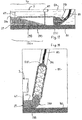
- FIG 14 and following, is illustrated a different laying solution without winch, so with less effort exerted on the pipe 3 (butted sections).
- the means 83 for supplying this material such as a flexible pipe, will favorably present an end opening 83 for discharging the material towards the bottom ( figure 18 ), or at the bottom ( figure 17 ) of the fluid 81 where the pipe is immersed, in and in contact with the casing 291 ballast.
- tubular envelope 291 forming a single longitudinal bead or a limited number of very elongated beads (each several hundreds to several thousand meters) will be chosen.
- the line 83 for supplying the ballast granular material 295 is fed from the surface 82. It can be expected that, just beyond the laying structure or ship 1 '' (typically behind), the pipe 83 is submerged in the tubular bead 291 (see Figures 17.18 ), parallel to the pipe, after (a priori on the floating structure 1 '') this pipe has been provided with its ballast system 290. It is recalled that at this moment, the latter returns, or not, then melt the pipe / ballast system, since the ballast itself is not necessarily present yet. On the other hand, the fastener 27 of the ballast system to the pipe has already been made, preferably downstream of the assembly of the pipe sections between them.
- a granular material such as sand
- the immersed pipe 3 (and filled with fresh water) will be allowed to oscillate (in seawater) with respect to the weighting system, according to non-stationary movements of the immersion liquid, while the mass ( 29,295) of the ballast system provided with its ballast maintains it essentially fixed (see double arrow figure 15 ).
- the solution of Figures 14-15 , 17-18 has the additional advantage of avoiding applying to the pipe, at the time of immersing it, the axial tensions imposed by the solution of the figure 1 and applied in particular by the winch 25.
- the pipe 3, to be immersed via the stern roll 73 of the ship 1 " is axially substantially stretched, but it is especially the already immersed mass of the elongated ribbon that forms part of pipe 3 already at the bottom and subject to the ballast (s) which ensures the descent to the bottom 80 of the suite of the assembly 3/290 (here not weighted during the descent), along an inclined slope 77 (see therefore figure 14 ), this in conjunction with the advance of the ship 1 "such that its longitudinal axis 10a, the 30 of the weighted pipe at the bottom and the direction of advance 75 are substantially parallel, the weighted pipe unwinding and landing at the bottom, behind the ship 1 ''.
- ballast ballast
Landscapes
- Engineering & Computer Science (AREA)
- General Engineering & Computer Science (AREA)
- Mechanical Engineering (AREA)
- Laying Of Electric Cables Or Lines Outside (AREA)
- Rigid Pipes And Flexible Pipes (AREA)
- Earth Drilling (AREA)
- Joints Allowing Movement (AREA)
- Quick-Acting Or Multi-Walled Pipe Joints (AREA)
- Other Liquid Machine Or Engine Such As Wave Power Use (AREA)
- Lining Or Joining Of Plastics Or The Like (AREA)
Claims (15)
- Gruppe, welche umfasst:- eine Transportleitung (3) für Flüssigkeit, wobei diese Leitung eine Längsachse aufweist und ist:dadurch gekennzeichnet, dass:-- flexibel,-- verformbar zwischen einem kreisförmigen Innenquerschnitt und einem abgeflachten Innenquerschnitt, der Null betragen kann,-- in Längsrichtung um sich selbst biegsam, und- eine Vorrichtung zum Verlegen der besagten Leitung an einem Ort, wobei die Verlegevorrichtung eine Längsachse aufweist und eine drehbare Trommel (15) umfasst, um welche herum ein erster Leitungsabschnitt gewickelt ist,- der besagte erste Leitungsabschnitt um die Trommel (15) herum in einem abgeflachten Zustand seines Querschnitts entsprechend einem abgeflachten Band gewickelt ist,- und die Verlegevorrichtung des Weiteren umfasst:-- eine motorisierte Haspel (17), um die Leitung abzuwickeln,-- Darbietungsmittel (19), um einander gegenüber, in einem gemeinhin formgegebenen, weniger abgeflachten Zustand ihres Querschnitts als auf der Trommel, den von der Trommel kommenden ersten Leitungsabschnitt und einen zweiten Abschnitt, welcher in Bezug auf die Verlegerichtung der Leitung stromabwärts des ersten gelegen ist, darzubieten,-- Verbindungsmittel (21, 22) für eine wasserdichte Verbindung zwischen dem ersten und zweiten Leitungsabschnitt in dem gemeinhin formgegebenen Zustand und das Erhalten der besagten verlängerten Leitung,-- und gegebenenfalls Spannmittel (23), um auf die verlängerte Leitung eine axiale Vorwärtsspannung stromabwärts und/oder Rückwärtsspannung stromaufwärts hin zu übertragen.
- Gruppe nach Anspruch 1, dadurch gekennzeichnet, dass die Darbietungsmittel (19) Formgebungsmittel des ersten und zweiten Leitungsabschnitts umfasst, wobei diese Formgebungsmittel stromaufwärts und stromabwärts der Verbindungsmittel Querschnitte aufweisen, welche jeweils entlang der Längsachse der Verlegevorrichtung von stromaufwärts nach stromabwärts hin zunehmen und abnehmen, und denen der besagte erste und zweite Leitungsabschnitt folgen, indem sie um und entlang dieser Querschnitte verlaufen.
- Gruppe nach Anspruch 1 oder 2, dadurch gekennzeichnet, dass:- die Trommel (15) eine Breite aufweist, welche senkrecht zur Längsachse der Leitung ausgerichtet ist, wobei diese Breite größer dem Halbumfang der Leitung in einem kreisförmigen Zustand des Querschnitts dieser Leitung ist,und die Leitung flach oder in einem Zustand, welcher einem solchen flachen Zustand unmittelbar nahe ist, senkrecht zu seiner Längsachse nicht um sich selbst gefaltet um die Trommel herumgewickelt ist, oder,- die Trommel eine Breite aufweist, welche senkrecht zur Längsachse der Leitung ausgerichtet ist, wobei diese Breite kleiner dem Halbumfang der Leitung in einem kreisförmigen Zustand des Querschnitts dieser Leitung ist, und die Leitung flach, senkrecht zu ihrer Längsachse um sich selbst gefaltet, um die Trommel gewickelt ist.
- Gruppe nach einem der vorstehenden Ansprüche, dadurch gekennzeichnet, dass die Darbietungsmittel umfassen:- ein erstes Element (190a, 190a1, 191a2), welches dazu bestimmt ist, über deren jeweils freie Enden im Inneren des ersten und zweiten Leitungsabschnitts aufgenommen zu werden,- ein zweites hohles Element (190b, 190b1, 191b2), welches so um das erste Element herum angeordnet ist, dass besagter erster und zweiter Leitungsabschnitt der Längsachse der Leitung entsprechend zwischen dem ersten und zweiten Element eingefügt werden können.
- Gruppe nach Anspruch 4, dadurch gekennzeichnet, dass mindestens eines von dem ersten und zweiten Element erste und zweite Antriebsmittel (191a1, 191b1, 191a2, 191b2) umfasst, welche zum Teil stromaufwärts und zum Teil stromabwärts der zu verbindenden freien Enden (30a, 30b) des besagten ersten und zweiten Leitungsabschnitts (3a, 3b) gelegen sind, um den ersten oder zweiten Leitungsabschnitt der Längsachse der Leitung nach anzutreiben, wobei der stromaufwärtige Teil (191a1, 191b1) der ersten und/oder zweiten Antriebsmittel dazu eingerichtet ist, vorübergehend den ersten Leitungsabschnitt (3a) der besagten Längsachse nach über eine vorbestimmte Distanz zu dem zweiten Leitungsabschnitt (3b) hin, oder umgekehrt, über den besagten stromabwärtigen Teil (191a2, 191b2), zu dem ersten Leitungsabschnitt (3a) hin anzutreiben.
- Gruppe nach Anspruch 5, dadurch gekennzeichnet, dass die zweiten Antriebsmittel mit Steuermitteln (63) verbunden sind, um:- wenn der erste und zweite Leitungsabschnitt (3a, 3b) noch nicht verbunden sind, den stromabwärtigen Teil (191a2, 191b2) der ersten und/oder zweiten Antriebsmittel im Hinblick auf den Antrieb des besagten zweiten Leitungsabschnitts zu deaktivieren, und,- wenn der erste und zweite Leitungsabschnitt (3a, 3b) durch die Verbindungsmittel (22) aneinandergefügt sind, den stromaufwärtigen Teil und/oder den stromabwärtigen Teil (191a2, 191b2) der ersten und/oder zweiten Antriebsmittel im Hinblick auf den Antrieb der besagten verbundenen Leitungsabschnitte zu aktivieren.
- Gruppe nach einem der Ansprüche 1 bis 6, welche ein Ballastsystem (29, 290, 295) umfasst, das im Wasser sinkt und das mit Befestigungsmitteln (27, 65, 67, 69) am besagten Ballastsystem an der Leitung (3) so verbunden ist, dass die Leitung und das Ballastsystem nicht einstückig sind.
- Gruppe nach Anspruch 7, wobei:- das Ballastsystem eine flexible Ballasthülle (291) umfasst, welche mindestens eine schlauchförmige Wulst formt und geeignet ist, ohne Vermischung mit der zu transportierenden Flüssigkeit einen Ballast (295) mit einer Dichte größer als der des Meerwassers zu enthalten,- und die Hülle (291), die mit der Leitung (3) leer oder im Wesentlichen leer auf mindestens einen Teil der Eintauchtiefe eingetaucht, anschließend so ballastbeschwert wird mittels einer Zuführleitung (83) des besagten granularen Materials, die von der Oberfläche (82) der Eintauchflüssigkeit her bespeist und in die schlauchförmige Wulst eingetaucht ist, danach strebt, in einer Flüssigkeit mit nicht stationären Bewegungen am Boden (80) der Eintauchstelle zu liegen.
- Gruppe nach einem der Ansprüche 7 oder 8, wobei die Befestigungsmittel (27) eine nachgiebige Verbindung (67, 69, 69b) umfassen, welche einen Abstand zwischen der Leitung und dem Ballastsystem gestatten, mit, in Abhängigkeit von nicht stationären Bewegungen der Eintauchflüssigkeit und während die Masse (29, 295) des mit seinem Ballast versehenen Ballastsystems dieses im Wesentlichen feststehend hält, einer Möglichkeit der Schwingung der eingetauchten Leitung in Bezug auf das besagte Ballastsystem (29, 290, 295).
- Gruppe nach Anspruch 7 oder den Ansprüchen 7 und 9,- wobei das Ballastsystem eine flexible Ballasthülle (291) umfasst, welche geeignet ist, ohne Vermischung mit der zu transportierenden Flüssigkeit einen Ballast (295) mit einer Dichte größer als der des Meerwassers zu enthalten, wobei die so ballastbeschwerte und in eine Flüssigkeit mit nicht stationären Bewegungen eingetauchte Hülle (291) danach strebt, am Boden (80) der Eintauchstelle zu liegen,- und welche Zuführmittel (83) für ein granulares Material als Ballast umfasst, wobei die besagten Zuführmittel (83) eine Öffnung (830) für die Einleitung des granularen Materials zum Boden hin oder am Boden der Flüssigkeit (81), in der die Leitung eingetaucht ist, in und in Berührung der Ballasthülle (291) mittels einer Zuführleitung (83) des besagten granularen Materials, welche von der Oberfläche (82) der Eintauchflüssigkeit her bespeist wird, aufweisen.
- Gruppe nach einem der Ansprüche 1 bis 6, dadurch gekennzeichnet, dass sie eine Winde (25) umfasst, um die besagte axiale Spannung mindestens für die Vorwärtsbewegung der verlängerten Leitung stromabwärts der Winde und wo diese Leitung mit ihrem abgeflachten oder unmittelbar nahen Innendurchmesser durchläuft, zu verstärken.
- Gruppe nach Anspruch 11, dadurch gekennzeichnet, dass die Winde eine Spillwirkung besitzt und so mehrere motorisierte Rollen umfasst, jeweils für die Übertragung eines Teils der axialen Spannung, und um welche herum, ohne vollständige Umrundung, die verlängerte Leitung mit ihrem abgeflachten oder unmittelbar nahen Querschnitt läuft.
- Schwimmstruktur, welche die Gruppe nach einem der vorstehenden Ansprüche umfasst, die auf einer Brücke (13) der Schwimmstruktur angeordnet ist.
- Schwimmstruktur nach Anspruch 13, dadurch gekennzeichnet, dass:- die Trommel (15) um eine horizontale Achse (15a) herumdreht,- die Trommel auf der Brücke (13) quer zur Längsachse (30) der Leitung beweglich ist und abnehmbar auf dieser Brücke montiert ist,- und ein Kran (31) für das Umsetzen der Trommeln auf der Brücke angeordnet ist, näher einem ersten Rand der Schwimmstruktur als einem zweiten, dem ersten gegenüberliegenden Rand, von dessen Seite eine zweite drehbare Trommel, um die herum ein dritter Leitungsabschnitt gewickelt ist, über besagten Kran auf der Brücke umgesetzt werden kann.
- Schwimmstruktur nach Anspruch 13, welche umfasst, um die besagte Leitung in das Wasser einzutauchen und sie am oder zu einem Boden (80) der Eintauchstelle hin zu halten, während diese Leitung nach und nach leer, unter Spannung, hinter der besagten Schwimmstruktur, die sich an der Oberfläche fortbewegt und mit der sie über die besagte Gruppe verbunden ist, eingetaucht wird:- Bewegungsmittel zum Navigieren, und- Zuführmittel (83) für Ballast (295), welche es gestatten, einen solchen Ballast dem Ballastsystem am oder zu dem besagten Eintauchboden (80) hin zuzuführen, wo ein erster Teil der Leitung und des Ballastsystems, mit dem sie verstehen ist, bereits gehalten wird von Ballast, welcher bereits in diesem ersten Teil des Ballastsystems vorhanden ist.
Applications Claiming Priority (2)
| Application Number | Priority Date | Filing Date | Title |
|---|---|---|---|
| FR1161294A FR2983933B1 (fr) | 2011-12-07 | 2011-12-07 | Ensemble pour l'installation sous-marine d'un tuyau flexible et deformable de transport de liquide, et structure flottante associee |
| PCT/FR2012/052825 WO2013083926A1 (fr) | 2011-12-07 | 2012-12-06 | Ensemble pour le transport de liquide par tuyauterie et structure flottante associee. |
Publications (2)
| Publication Number | Publication Date |
|---|---|
| EP2788643A1 EP2788643A1 (de) | 2014-10-15 |
| EP2788643B1 true EP2788643B1 (de) | 2016-09-14 |
Family
ID=47295054
Family Applications (2)
| Application Number | Title | Priority Date | Filing Date |
|---|---|---|---|
| EP12810363.7A Active EP2788643B1 (de) | 2011-12-07 | 2012-12-06 | Anordnung zum fluidtransport durch eine rohrleitung und zugehörige schwimmende struktur |
| EP12810364.5A Withdrawn EP2788644A1 (de) | 2011-12-07 | 2012-12-06 | Implementierung eines fluidbeförderungsrohrs mit flexibler halterung |
Family Applications After (1)
| Application Number | Title | Priority Date | Filing Date |
|---|---|---|---|
| EP12810364.5A Withdrawn EP2788644A1 (de) | 2011-12-07 | 2012-12-06 | Implementierung eines fluidbeförderungsrohrs mit flexibler halterung |
Country Status (8)
| Country | Link |
|---|---|
| US (2) | US9651168B2 (de) |
| EP (2) | EP2788643B1 (de) |
| CL (2) | CL2014001494A1 (de) |
| ES (1) | ES2606020T3 (de) |
| FR (2) | FR2983933B1 (de) |
| MA (2) | MA35824B1 (de) |
| PE (2) | PE20142048A1 (de) |
| WO (2) | WO2013083927A1 (de) |
Families Citing this family (6)
| Publication number | Priority date | Publication date | Assignee | Title |
|---|---|---|---|---|
| FR2996621B1 (fr) * | 2012-10-05 | 2014-12-26 | Via Marina | Procede et dispositif de pose d'un tuyau sous marin. |
| FR3006028B1 (fr) | 2013-05-22 | 2015-12-25 | Bblm Associes | Tuyau flexible pour le transport d'eau douce, ensemble pour son stockage et assemblage de plusieurs tuyaux. |
| NL2018078B1 (en) * | 2016-12-23 | 2018-07-02 | Tideway B V | Device and method for paying out an elongated flexible article from a vessel |
| JP7539025B2 (ja) * | 2018-09-28 | 2024-08-23 | 大日本印刷株式会社 | 包装材料及び包装容器 |
| CN113673076B (zh) * | 2021-07-09 | 2022-09-02 | 华南理工大学 | 一种适用于海洋浮式结构的动力响应求解方法 |
| BR102021015706A2 (pt) * | 2021-08-10 | 2023-02-14 | Petróleo Brasileiro S.A. - Petrobras | Sistema e método de reel drive submarino para recolhimento e lançamento de dutos flexíveis e umbilicais |
Family Cites Families (22)
| Publication number | Priority date | Publication date | Assignee | Title |
|---|---|---|---|---|
| US3120107A (en) * | 1958-12-04 | 1964-02-04 | Juusela Taneli | Method of and a device for making drain pipes |
| US3086369A (en) * | 1961-10-02 | 1963-04-23 | Aluminum Co Of America | Underwater pipe line and method |
| FR1417987A (fr) * | 1963-01-22 | 1965-11-19 | Inst Francais Du Petrole | Conduite souple armée |
| US3494813A (en) * | 1965-11-08 | 1970-02-10 | John E Lawrence | Method of lining a pipe using fluid pressure in the form of a vacuum |
| US3631933A (en) * | 1968-07-22 | 1972-01-04 | John Dennis Bryant | Fluid flow system for wells |
| AU458950B2 (en) * | 1972-05-29 | 1975-03-13 | Swiss Aluminium Aust. Ltd. | Submarine pipelines |
| FR2260051A1 (en) * | 1974-02-04 | 1975-08-29 | Sedec | Method of placing undersea piping - uses collapsible fluid filled tube gives buoyancy to prevent kinking of piping |
| GR59794B (en) * | 1975-03-27 | 1978-02-28 | Doris Dev Richesse Sous Marine | Laying pipes under-water |
| FR2312713A1 (fr) * | 1975-05-30 | 1976-12-24 | Doris Dev Richesse Sous Marine | Procede et dispositif de mise en place d'une conduite immergee, telle qu'une conduite sous-marine |
| US4310264A (en) * | 1980-03-31 | 1982-01-12 | Brownlee William L | Buoyant pipe system |
| FR2479943B1 (fr) * | 1980-04-04 | 1985-07-05 | Petroles Cie Francaise | Procede et ligne de depose d'une conduite en mer |
| DE3590520C2 (de) * | 1984-10-17 | 1989-10-26 | Trest "Juzvodoprovod", Krasnodar, Su | |
| US5169264A (en) * | 1990-04-05 | 1992-12-08 | Kidoh Technical Ins. Co., Ltd. | Propulsion process of buried pipe |
| FR2786246B1 (fr) * | 1998-11-19 | 2001-02-09 | Felix Bogliolo | Tuyau pour le transport de liquide dans un milieu marin et son procede de fabrication |
| CA2277523C (en) * | 1999-07-16 | 2004-02-17 | Glen Alvin Jewell | Pipeline weight |
| AU2003218543A1 (en) * | 2002-03-27 | 2003-10-08 | Sergio Pinheiro Torggler | A flexible duct for transporting fluids, and use of a flexible duct for transportating fluids |
| BR0316200A (pt) * | 2002-11-13 | 2005-10-04 | Wellstream Int Ltd | Tubo flexìvel flectìvel e processo de fabricação do mesmo |
| US6926037B2 (en) | 2002-12-17 | 2005-08-09 | Wellstream International Limited | Collapse tolerant flexible pipe and method of manufacturing same |
| FR2859265B1 (fr) | 2003-09-03 | 2005-11-18 | Felix Bogliolo | Lestage de tuyau pour le transport de liquide dans un milieu marin |
| CA2488145A1 (en) * | 2004-11-22 | 2006-05-22 | Hydrotech Dynamics Ltd. | Pipeline ballast and method of use |
| WO2008062081A2 (es) * | 2006-11-17 | 2008-05-29 | Alapont Tatay Jose | Procedimiento y equipo para la distribución y reaprovechamiento del agua |
| CN102221128B (zh) * | 2011-06-09 | 2015-05-13 | 浙江大学 | 一种基于锚墩固定的海底输油输气软管管线 |
-
2011
- 2011-12-07 FR FR1161294A patent/FR2983933B1/fr active Active
-
2012
- 2012-10-05 FR FR1259533A patent/FR2983934B1/fr active Active
- 2012-12-06 WO PCT/FR2012/052826 patent/WO2013083927A1/fr not_active Ceased
- 2012-12-06 US US14/363,931 patent/US9651168B2/en not_active Expired - Fee Related
- 2012-12-06 PE PE2014000919A patent/PE20142048A1/es active IP Right Grant
- 2012-12-06 ES ES12810363.7T patent/ES2606020T3/es active Active
- 2012-12-06 WO PCT/FR2012/052825 patent/WO2013083926A1/fr not_active Ceased
- 2012-12-06 EP EP12810363.7A patent/EP2788643B1/de active Active
- 2012-12-06 EP EP12810364.5A patent/EP2788644A1/de not_active Withdrawn
- 2012-12-06 PE PE2014000918A patent/PE20142049A1/es active IP Right Grant
- 2012-12-06 US US14/363,924 patent/US9212763B2/en not_active Expired - Fee Related
-
2014
- 2014-06-05 MA MA37105A patent/MA35824B1/fr unknown
- 2014-06-05 MA MA37106A patent/MA35825B1/fr unknown
- 2014-06-06 CL CL2014001494A patent/CL2014001494A1/es unknown
- 2014-06-06 CL CL2014001495A patent/CL2014001495A1/es unknown
Non-Patent Citations (1)
| Title |
|---|
| ANONYMOUS: "Submariver. Transportation of water in large quantities and over long distances by underwater flexible pipe", 1 January 2010 (2010-01-01), XP054975713, Retrieved from the Internet <URL:http://www.via-marina.com/fr/film.php?lang=gb> [retrieved on 20150421] * |
Also Published As
| Publication number | Publication date |
|---|---|
| EP2788644A1 (de) | 2014-10-15 |
| FR2983934A1 (fr) | 2013-06-14 |
| FR2983934B1 (fr) | 2015-01-02 |
| FR2983933B1 (fr) | 2014-02-07 |
| US20140352806A1 (en) | 2014-12-04 |
| US9651168B2 (en) | 2017-05-16 |
| CL2014001495A1 (es) | 2015-02-27 |
| MA35825B1 (fr) | 2014-12-01 |
| US9212763B2 (en) | 2015-12-15 |
| WO2013083927A1 (fr) | 2013-06-13 |
| PE20142049A1 (es) | 2014-12-15 |
| EP2788643A1 (de) | 2014-10-15 |
| WO2013083926A1 (fr) | 2013-06-13 |
| FR2983933A1 (fr) | 2013-06-14 |
| US20150010360A1 (en) | 2015-01-08 |
| ES2606020T3 (es) | 2017-03-17 |
| CL2014001494A1 (es) | 2015-02-27 |
| PE20142048A1 (es) | 2014-12-15 |
| MA35824B1 (fr) | 2014-12-01 |
Similar Documents
| Publication | Publication Date | Title |
|---|---|---|
| EP2788643B1 (de) | Anordnung zum fluidtransport durch eine rohrleitung und zugehörige schwimmende struktur | |
| EP2633215B1 (de) | Modulare vorrichtung zur speicherung und handhabung einer vielzahl von biegsamen rohren | |
| CA2380816A1 (fr) | Dispositif de mise a l'eau et de recuperation d'un vehicule sous-marin et procede de mise en oeuvre | |
| EP1092108A1 (de) | Schiff zum verlegen von starren rohrleitungen in grosser tiefe | |
| FR2590539A1 (fr) | Systeme d'amarrage a cable unique, et procede de realisation d'un terminal de haute mer utilisant un tel systeme | |
| EP3209546B1 (de) | System zum aussetzen und bergen von see- und unterseevorrichtungen mit unterstützung durch kippbare schutzkomponenten | |
| EP1606160B1 (de) | Vorrichtung und verfahren für die stabilisierung und kontrolle der niedergang und des aufstiegs einer schweren struktur zwischen meeresoberfläche und meeresboden | |
| EP0474845B1 (de) | Verfahren zum verlegen von biegsamen rohrförmigen leitungen mittels einer vielzahl von schiffen | |
| EP1581760B1 (de) | Herstellungseinheit für starrgewalzte Rohrleitung | |
| FR2705640A1 (fr) | Procédé et dispositif de levage de manutention de charge en mer. | |
| WO2014108631A1 (fr) | Barge flottante submersible | |
| FR2967749A1 (fr) | Dispositif de mise sous tension et de serrage d'un element allonge de forme tubulaire | |
| EP0677437A1 (de) | Verfahren und Vorrichtung gegen die Längsbewegung von Wasserfahrzeugen | |
| FR2543613A1 (fr) | Procede et dispositif pour installer un bloc de masse importante au fond de l'eau | |
| FR3045559A1 (fr) | Dispositif pour la manoeuvre et le stockage d'un cordage, en particulier une aussiere de navire | |
| EP1167178B1 (de) | Schutzvorrichtung für ein Versorgungskabel eines Unterwassergegenstandes | |
| BE561390A (de) | ||
| FR2996622A1 (fr) | Mise en œuvre d'un tuyau de transport de fluide a lest granulaire | |
| FR2668446A1 (fr) | Perfectionnements apportes aux engins sous-marins filo-guides. | |
| OA16472A (fr) | Dispositif de pose d'une conduite dans une étendue d'eau, structure et procédé associés | |
| BE399992A (de) |
Legal Events
| Date | Code | Title | Description |
|---|---|---|---|
| PUAI | Public reference made under article 153(3) epc to a published international application that has entered the european phase |
Free format text: ORIGINAL CODE: 0009012 |
|
| 17P | Request for examination filed |
Effective date: 20140606 |
|
| AK | Designated contracting states |
Kind code of ref document: A1 Designated state(s): AL AT BE BG CH CY CZ DE DK EE ES FI FR GB GR HR HU IE IS IT LI LT LU LV MC MK MT NL NO PL PT RO RS SE SI SK SM TR |
|
| DAX | Request for extension of the european patent (deleted) | ||
| 17Q | First examination report despatched |
Effective date: 20150601 |
|
| GRAP | Despatch of communication of intention to grant a patent |
Free format text: ORIGINAL CODE: EPIDOSNIGR1 |
|
| INTG | Intention to grant announced |
Effective date: 20160421 |
|
| GRAS | Grant fee paid |
Free format text: ORIGINAL CODE: EPIDOSNIGR3 |
|
| GRAA | (expected) grant |
Free format text: ORIGINAL CODE: 0009210 |
|
| AK | Designated contracting states |
Kind code of ref document: B1 Designated state(s): AL AT BE BG CH CY CZ DE DK EE ES FI FR GB GR HR HU IE IS IT LI LT LU LV MC MK MT NL NO PL PT RO RS SE SI SK SM TR |
|
| REG | Reference to a national code |
Ref country code: GB Ref legal event code: FG4D Free format text: NOT ENGLISH |
|
| REG | Reference to a national code |
Ref country code: CH Ref legal event code: EP |
|
| REG | Reference to a national code |
Ref country code: IE Ref legal event code: FG4D Free format text: LANGUAGE OF EP DOCUMENT: FRENCH |
|
| REG | Reference to a national code |
Ref country code: FR Ref legal event code: PLFP Year of fee payment: 5 |
|
| REG | Reference to a national code |
Ref country code: AT Ref legal event code: REF Ref document number: 829390 Country of ref document: AT Kind code of ref document: T Effective date: 20161015 |
|
| REG | Reference to a national code |
Ref country code: DE Ref legal event code: R096 Ref document number: 602012023047 Country of ref document: DE |
|
| REG | Reference to a national code |
Ref country code: LT Ref legal event code: MG4D |
|
| REG | Reference to a national code |
Ref country code: NL Ref legal event code: MP Effective date: 20160914 |
|
| PG25 | Lapsed in a contracting state [announced via postgrant information from national office to epo] |
Ref country code: HR Free format text: LAPSE BECAUSE OF FAILURE TO SUBMIT A TRANSLATION OF THE DESCRIPTION OR TO PAY THE FEE WITHIN THE PRESCRIBED TIME-LIMIT Effective date: 20160914 Ref country code: NO Free format text: LAPSE BECAUSE OF FAILURE TO SUBMIT A TRANSLATION OF THE DESCRIPTION OR TO PAY THE FEE WITHIN THE PRESCRIBED TIME-LIMIT Effective date: 20161214 Ref country code: LT Free format text: LAPSE BECAUSE OF FAILURE TO SUBMIT A TRANSLATION OF THE DESCRIPTION OR TO PAY THE FEE WITHIN THE PRESCRIBED TIME-LIMIT Effective date: 20160914 Ref country code: RS Free format text: LAPSE BECAUSE OF FAILURE TO SUBMIT A TRANSLATION OF THE DESCRIPTION OR TO PAY THE FEE WITHIN THE PRESCRIBED TIME-LIMIT Effective date: 20160914 Ref country code: FI Free format text: LAPSE BECAUSE OF FAILURE TO SUBMIT A TRANSLATION OF THE DESCRIPTION OR TO PAY THE FEE WITHIN THE PRESCRIBED TIME-LIMIT Effective date: 20160914 |
|
| REG | Reference to a national code |
Ref country code: AT Ref legal event code: MK05 Ref document number: 829390 Country of ref document: AT Kind code of ref document: T Effective date: 20160914 |
|
| PG25 | Lapsed in a contracting state [announced via postgrant information from national office to epo] |
Ref country code: LV Free format text: LAPSE BECAUSE OF FAILURE TO SUBMIT A TRANSLATION OF THE DESCRIPTION OR TO PAY THE FEE WITHIN THE PRESCRIBED TIME-LIMIT Effective date: 20160914 Ref country code: NL Free format text: LAPSE BECAUSE OF FAILURE TO SUBMIT A TRANSLATION OF THE DESCRIPTION OR TO PAY THE FEE WITHIN THE PRESCRIBED TIME-LIMIT Effective date: 20160914 Ref country code: GR Free format text: LAPSE BECAUSE OF FAILURE TO SUBMIT A TRANSLATION OF THE DESCRIPTION OR TO PAY THE FEE WITHIN THE PRESCRIBED TIME-LIMIT Effective date: 20161215 Ref country code: SE Free format text: LAPSE BECAUSE OF FAILURE TO SUBMIT A TRANSLATION OF THE DESCRIPTION OR TO PAY THE FEE WITHIN THE PRESCRIBED TIME-LIMIT Effective date: 20160914 |
|
| REG | Reference to a national code |
Ref country code: ES Ref legal event code: FG2A Ref document number: 2606020 Country of ref document: ES Kind code of ref document: T3 Effective date: 20170317 |
|
| PG25 | Lapsed in a contracting state [announced via postgrant information from national office to epo] |
Ref country code: EE Free format text: LAPSE BECAUSE OF FAILURE TO SUBMIT A TRANSLATION OF THE DESCRIPTION OR TO PAY THE FEE WITHIN THE PRESCRIBED TIME-LIMIT Effective date: 20160914 Ref country code: RO Free format text: LAPSE BECAUSE OF FAILURE TO SUBMIT A TRANSLATION OF THE DESCRIPTION OR TO PAY THE FEE WITHIN THE PRESCRIBED TIME-LIMIT Effective date: 20160914 |
|
| PG25 | Lapsed in a contracting state [announced via postgrant information from national office to epo] |
Ref country code: BE Free format text: LAPSE BECAUSE OF NON-PAYMENT OF DUE FEES Effective date: 20161231 Ref country code: PL Free format text: LAPSE BECAUSE OF FAILURE TO SUBMIT A TRANSLATION OF THE DESCRIPTION OR TO PAY THE FEE WITHIN THE PRESCRIBED TIME-LIMIT Effective date: 20160914 Ref country code: AT Free format text: LAPSE BECAUSE OF FAILURE TO SUBMIT A TRANSLATION OF THE DESCRIPTION OR TO PAY THE FEE WITHIN THE PRESCRIBED TIME-LIMIT Effective date: 20160914 Ref country code: CZ Free format text: LAPSE BECAUSE OF FAILURE TO SUBMIT A TRANSLATION OF THE DESCRIPTION OR TO PAY THE FEE WITHIN THE PRESCRIBED TIME-LIMIT Effective date: 20160914 Ref country code: BG Free format text: LAPSE BECAUSE OF FAILURE TO SUBMIT A TRANSLATION OF THE DESCRIPTION OR TO PAY THE FEE WITHIN THE PRESCRIBED TIME-LIMIT Effective date: 20161214 Ref country code: SK Free format text: LAPSE BECAUSE OF FAILURE TO SUBMIT A TRANSLATION OF THE DESCRIPTION OR TO PAY THE FEE WITHIN THE PRESCRIBED TIME-LIMIT Effective date: 20160914 Ref country code: IS Free format text: LAPSE BECAUSE OF FAILURE TO SUBMIT A TRANSLATION OF THE DESCRIPTION OR TO PAY THE FEE WITHIN THE PRESCRIBED TIME-LIMIT Effective date: 20170114 Ref country code: PT Free format text: LAPSE BECAUSE OF FAILURE TO SUBMIT A TRANSLATION OF THE DESCRIPTION OR TO PAY THE FEE WITHIN THE PRESCRIBED TIME-LIMIT Effective date: 20170116 Ref country code: SM Free format text: LAPSE BECAUSE OF FAILURE TO SUBMIT A TRANSLATION OF THE DESCRIPTION OR TO PAY THE FEE WITHIN THE PRESCRIBED TIME-LIMIT Effective date: 20160914 |
|
| REG | Reference to a national code |
Ref country code: DE Ref legal event code: R097 Ref document number: 602012023047 Country of ref document: DE |
|
| PG25 | Lapsed in a contracting state [announced via postgrant information from national office to epo] |
Ref country code: IT Free format text: LAPSE BECAUSE OF FAILURE TO SUBMIT A TRANSLATION OF THE DESCRIPTION OR TO PAY THE FEE WITHIN THE PRESCRIBED TIME-LIMIT Effective date: 20160914 |
|
| REG | Reference to a national code |
Ref country code: DE Ref legal event code: R119 Ref document number: 602012023047 Country of ref document: DE |
|
| PLBE | No opposition filed within time limit |
Free format text: ORIGINAL CODE: 0009261 |
|
| STAA | Information on the status of an ep patent application or granted ep patent |
Free format text: STATUS: NO OPPOSITION FILED WITHIN TIME LIMIT |
|
| PG25 | Lapsed in a contracting state [announced via postgrant information from national office to epo] |
Ref country code: DK Free format text: LAPSE BECAUSE OF FAILURE TO SUBMIT A TRANSLATION OF THE DESCRIPTION OR TO PAY THE FEE WITHIN THE PRESCRIBED TIME-LIMIT Effective date: 20160914 |
|
| REG | Reference to a national code |
Ref country code: CH Ref legal event code: PL |
|
| 26N | No opposition filed |
Effective date: 20170615 |
|
| GBPC | Gb: european patent ceased through non-payment of renewal fee |
Effective date: 20161214 |
|
| PG25 | Lapsed in a contracting state [announced via postgrant information from national office to epo] |
Ref country code: MC Free format text: LAPSE BECAUSE OF FAILURE TO SUBMIT A TRANSLATION OF THE DESCRIPTION OR TO PAY THE FEE WITHIN THE PRESCRIBED TIME-LIMIT Effective date: 20160914 |
|
| REG | Reference to a national code |
Ref country code: IE Ref legal event code: MM4A |
|
| REG | Reference to a national code |
Ref country code: FR Ref legal event code: PLFP Year of fee payment: 6 |
|
| PG25 | Lapsed in a contracting state [announced via postgrant information from national office to epo] |
Ref country code: LU Free format text: LAPSE BECAUSE OF NON-PAYMENT OF DUE FEES Effective date: 20161206 Ref country code: CH Free format text: LAPSE BECAUSE OF NON-PAYMENT OF DUE FEES Effective date: 20161231 Ref country code: LI Free format text: LAPSE BECAUSE OF NON-PAYMENT OF DUE FEES Effective date: 20161231 |
|
| PG25 | Lapsed in a contracting state [announced via postgrant information from national office to epo] |
Ref country code: IE Free format text: LAPSE BECAUSE OF NON-PAYMENT OF DUE FEES Effective date: 20161206 Ref country code: GB Free format text: LAPSE BECAUSE OF NON-PAYMENT OF DUE FEES Effective date: 20161214 Ref country code: DE Free format text: LAPSE BECAUSE OF NON-PAYMENT OF DUE FEES Effective date: 20170701 Ref country code: SI Free format text: LAPSE BECAUSE OF FAILURE TO SUBMIT A TRANSLATION OF THE DESCRIPTION OR TO PAY THE FEE WITHIN THE PRESCRIBED TIME-LIMIT Effective date: 20160914 |
|
| REG | Reference to a national code |
Ref country code: BE Ref legal event code: MM Effective date: 20161231 |
|
| PG25 | Lapsed in a contracting state [announced via postgrant information from national office to epo] |
Ref country code: HU Free format text: LAPSE BECAUSE OF FAILURE TO SUBMIT A TRANSLATION OF THE DESCRIPTION OR TO PAY THE FEE WITHIN THE PRESCRIBED TIME-LIMIT; INVALID AB INITIO Effective date: 20121206 |
|
| PG25 | Lapsed in a contracting state [announced via postgrant information from national office to epo] |
Ref country code: CY Free format text: LAPSE BECAUSE OF FAILURE TO SUBMIT A TRANSLATION OF THE DESCRIPTION OR TO PAY THE FEE WITHIN THE PRESCRIBED TIME-LIMIT Effective date: 20160914 Ref country code: MK Free format text: LAPSE BECAUSE OF FAILURE TO SUBMIT A TRANSLATION OF THE DESCRIPTION OR TO PAY THE FEE WITHIN THE PRESCRIBED TIME-LIMIT Effective date: 20160914 |
|
| PG25 | Lapsed in a contracting state [announced via postgrant information from national office to epo] |
Ref country code: MT Free format text: LAPSE BECAUSE OF FAILURE TO SUBMIT A TRANSLATION OF THE DESCRIPTION OR TO PAY THE FEE WITHIN THE PRESCRIBED TIME-LIMIT Effective date: 20160914 |
|
| PG25 | Lapsed in a contracting state [announced via postgrant information from national office to epo] |
Ref country code: TR Free format text: LAPSE BECAUSE OF FAILURE TO SUBMIT A TRANSLATION OF THE DESCRIPTION OR TO PAY THE FEE WITHIN THE PRESCRIBED TIME-LIMIT Effective date: 20160914 Ref country code: AL Free format text: LAPSE BECAUSE OF FAILURE TO SUBMIT A TRANSLATION OF THE DESCRIPTION OR TO PAY THE FEE WITHIN THE PRESCRIBED TIME-LIMIT Effective date: 20160914 |
|
| PGFP | Annual fee paid to national office [announced via postgrant information from national office to epo] |
Ref country code: ES Payment date: 20250117 Year of fee payment: 13 |
|
| PGFP | Annual fee paid to national office [announced via postgrant information from national office to epo] |
Ref country code: FR Payment date: 20251222 Year of fee payment: 14 |