EP2788624B1 - Pompe utilisant de l'électronique multitension et équipée d'une protection contre le fonctionnement à sec et la surintensité - Google Patents
Pompe utilisant de l'électronique multitension et équipée d'une protection contre le fonctionnement à sec et la surintensité Download PDFInfo
- Publication number
- EP2788624B1 EP2788624B1 EP12856042.2A EP12856042A EP2788624B1 EP 2788624 B1 EP2788624 B1 EP 2788624B1 EP 12856042 A EP12856042 A EP 12856042A EP 2788624 B1 EP2788624 B1 EP 2788624B1
- Authority
- EP
- European Patent Office
- Prior art keywords
- pump
- predetermined
- current level
- signal processor
- run
- Prior art date
- Legal status (The legal status is an assumption and is not a legal conclusion. Google has not performed a legal analysis and makes no representation as to the accuracy of the status listed.)
- Active
Links
- 230000011664 signaling Effects 0.000 claims description 44
- 238000000034 method Methods 0.000 claims description 19
- 238000004590 computer program Methods 0.000 claims description 7
- 230000004397 blinking Effects 0.000 claims description 4
- 239000012530 fluid Substances 0.000 description 6
- 238000005086 pumping Methods 0.000 description 4
- 238000010586 diagram Methods 0.000 description 3
- 238000012545 processing Methods 0.000 description 3
- 239000007788 liquid Substances 0.000 description 2
- 238000006073 displacement reaction Methods 0.000 description 1
- 238000005516 engineering process Methods 0.000 description 1
- 238000012423 maintenance Methods 0.000 description 1
- 239000000463 material Substances 0.000 description 1
- 238000012986 modification Methods 0.000 description 1
- 230000004048 modification Effects 0.000 description 1
- 239000007787 solid Substances 0.000 description 1
Images


Classifications
-
- F—MECHANICAL ENGINEERING; LIGHTING; HEATING; WEAPONS; BLASTING
- F04—POSITIVE - DISPLACEMENT MACHINES FOR LIQUIDS; PUMPS FOR LIQUIDS OR ELASTIC FLUIDS
- F04D—NON-POSITIVE-DISPLACEMENT PUMPS
- F04D15/00—Control, e.g. regulation, of pumps, pumping installations or systems
- F04D15/02—Stopping of pumps, or operating valves, on occurrence of unwanted conditions
- F04D15/0245—Stopping of pumps, or operating valves, on occurrence of unwanted conditions responsive to a condition of the pump
-
- F—MECHANICAL ENGINEERING; LIGHTING; HEATING; WEAPONS; BLASTING
- F04—POSITIVE - DISPLACEMENT MACHINES FOR LIQUIDS; PUMPS FOR LIQUIDS OR ELASTIC FLUIDS
- F04B—POSITIVE-DISPLACEMENT MACHINES FOR LIQUIDS; PUMPS
- F04B17/00—Pumps characterised by combination with, or adaptation to, specific driving engines or motors
- F04B17/03—Pumps characterised by combination with, or adaptation to, specific driving engines or motors driven by electric motors
-
- F—MECHANICAL ENGINEERING; LIGHTING; HEATING; WEAPONS; BLASTING
- F04—POSITIVE - DISPLACEMENT MACHINES FOR LIQUIDS; PUMPS FOR LIQUIDS OR ELASTIC FLUIDS
- F04B—POSITIVE-DISPLACEMENT MACHINES FOR LIQUIDS; PUMPS
- F04B49/00—Control, e.g. of pump delivery, or pump pressure of, or safety measures for, machines, pumps, or pumping installations, not otherwise provided for, or of interest apart from, groups F04B1/00 - F04B47/00
- F04B49/06—Control using electricity
- F04B49/065—Control using electricity and making use of computers
-
- F—MECHANICAL ENGINEERING; LIGHTING; HEATING; WEAPONS; BLASTING
- F04—POSITIVE - DISPLACEMENT MACHINES FOR LIQUIDS; PUMPS FOR LIQUIDS OR ELASTIC FLUIDS
- F04B—POSITIVE-DISPLACEMENT MACHINES FOR LIQUIDS; PUMPS
- F04B2201/00—Pump parameters
- F04B2201/02—Piston parameters
- F04B2201/0207—Number of pumping strokes in unit time
-
- F—MECHANICAL ENGINEERING; LIGHTING; HEATING; WEAPONS; BLASTING
- F04—POSITIVE - DISPLACEMENT MACHINES FOR LIQUIDS; PUMPS FOR LIQUIDS OR ELASTIC FLUIDS
- F04B—POSITIVE-DISPLACEMENT MACHINES FOR LIQUIDS; PUMPS
- F04B2203/00—Motor parameters
- F04B2203/02—Motor parameters of rotating electric motors
- F04B2203/0201—Current
-
- F—MECHANICAL ENGINEERING; LIGHTING; HEATING; WEAPONS; BLASTING
- F04—POSITIVE - DISPLACEMENT MACHINES FOR LIQUIDS; PUMPS FOR LIQUIDS OR ELASTIC FLUIDS
- F04B—POSITIVE-DISPLACEMENT MACHINES FOR LIQUIDS; PUMPS
- F04B2203/00—Motor parameters
- F04B2203/02—Motor parameters of rotating electric motors
- F04B2203/0202—Voltage
Definitions
- the present invention relates to a pump; and more particularly to a pump using multi voltage electronics for providing run dry and over current protection to a particular pump model.
- PCBA printed circuit board assembly
- the invention includes an apparatus such a printed circuit board (PCBA) according to claim 1 and a pump comprising the PCBA.
- PCBA printed circuit board
- the signal processor is configured to provide control signalling to shut off the pump after the predetermined time if the particular current draw of the pump is lower than the predetermined particular low current level or is higher than the predetermined particular high current level, where the predetermined particular low current level and the predetermined particular high current level depend on the particular voltage being supplied to the particular motor to run the particular pump model.
- the present invention may include one or more of the following features:
- the signal processor may be configured to provide control signalling to shut off the pump after the predetermined time if the current draw of the pump is lower than the predetermined low current level or is higher than the predetermined high current level, where the predetermined low current level and the predetermined high current level depend on the voltage being supplied to the motor to run the particular pump model.
- the signal processor may be configured to provide the control signalling to shut the pump off in order to protect the pump against a run dry and/or over current conditions of the pump.
- the control signalling may include blinking a rocker lamp if the particular current draw of the particular pump model is either lower than the predetermined particular low current level or higher than the predetermined particular high current level.
- the signal processor may be configured, programmed or adapted to run on the particular pump model having one input voltage, and may also be configured, programmed or adapted to run on a different particular pump model having a different input voltage.
- the signal processor including the PCBA, may be configured with a respective software routine for each particular pump model, and implement the appropriate software routine based at least partly on the voltage being supplied to the motor to run the particular pump model.
- the PCBA may be configured universally to run on numerous pump models.
- the particular pump model forms part of a series of pumps having different voltage requirements, including a 12 volt pump, a 24 volt pump, or a 32 volt pump, etc.
- each particular pump model has a respective motor having a corresponding voltage requirement.
- the pump may contain the PCBA inside its housing.
- the present invention takes also the form of a method according to the features of claim 9, including steps for receive signaling containing information about a voltage being supplied to a motor to run a particular pump model, and also containing information about whether a current draw of the pump is lower than a predetermined low current level or is higher than a predetermined high current level; and determining whether to shut off the pump after a predetermined time, based at least partly on the signaling received.
- the method may also include providing control signalling to shut off the pump after the predetermined time if the particular current draw of the particular pump model is lower than the predetermined particular low current level or is higher than the predetermined particular high current level, where the predetermined particular low current level and the predetermined particular high current level depend on the particular voltage being supplied to the particular motor to run the particular pump model, as well as one or more of the other features set forth above.
- the present invention may also take the form of a printed circuit board assembly (PCBA) according to the features of claim 13.
- PCBA printed circuit board assembly
- FIG. 1 The Basic Pump 10
- Figure 1 shows the present invention in the form of a pump generally indicated as 10 that includes a signal processor, including where the signal processor forms part of a printed circuit board assembly (PCBA) 12, configured to receive signaling containing information about a voltage being supplied to a motor to run a particular pump model, and also containing information about whether a current draw of the pump is lower than a predetermined low current level or is higher than a predetermined high current level; and determine whether to shut off the pump after a predetermined time, based at least partly on the signaling received.
- PCBA printed circuit board assembly
- the pump 10 may also include other pump components and parts generally indicated as 14 in Figure 1 that do not form part of the underlying invention, e.g., including a motor 14a, on/off switch 14b, a power supply jack 14c, a pressure switch 14d and a front end pumping portion 14e, as shown in Figures 2 and 3 .
- the power supply jack 14c is configured for receiving or accepting 12/24/(possibly 32V+ as well) VDC as well as utilize an external wall mounted power supply to convert 115/230 VAC to run one pump model.
- the pressure switches like element 14d are known in the art, may be configured to sense the pressure of fluid being pumped, and provide corresponding signaling, e.g.
- Front end pumping portion like element 14e may be configured for pumping the fluid or liquid of interest by the pump 10 and are known in the art, such that the scope of the invention is not intended to be limited to any particular type, kind or configuration of the same.
- the signal processor including the PCBA 12, may be configured to provide control signalling to shut off the pump 10 after the predetermined time, e.g., if the current draw of the pump 10 is lower than the predetermined low current level or is higher than the predetermined high current level, where the predetermined low current level and the predetermined high current level depend on the voltage being supplied to the motor 14a ( Figure 2 ) to run the particular pump model.
- the control signalling may contain information for turning or switching off the motor 14a.
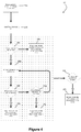
- the signal processor including the PCBA 12, may be configured to provide the control signalling to shut the pump 10 off in order to protect the pump 10 against a run dry and/or over current conditions of the pump, consistent with the pump control routine generally indicated as 20 shown in Figure 4 . For example, see steps 20d, 20h and 20k.
- the control signalling may include blinking a rocker lamp when if the current draw of the pump is either lower than the predetermined low current level or higher than the predetermined high current level, consistent with the pump control routine 20 shown in Figure 4 . Again, see the steps 20d, 20h and 20k.
- the control signalling may include turning a rocker lamp solid when power is removed from the pump 10. See steps 20g and 20i.
- the signal processor including the PCBA 12, may be configured and programmed to run on the particular pump model having one input voltage, and may also be configured, programmed and/or suitably to run on a different particular pump model having a different input voltage for running a pump motor.
- the signal processor including the PCBA 12, may be configured with at least one processor and at least one memory including computer program code, the at least one memory and computer program code configured, with the at least one processor, to cause the signal processor to receive the signaling containing information about the voltage being supplied to the motor to run the particular pump model, and also containing information about whether the current draw of the pump is lower than the predetermined low current level or is higher than the predetermined high current level; and determine whether to shut off the pump after the predetermined time, based at least partly on the signaling received.
- the present invention may also take the form of a method including steps for receive signaling containing information about a voltage being supplied to a motor such as 14a ( Figure 2 ) to run a particular pump model, and also containing information about whether a current draw of the pump 10 is lower than a predetermined low current level or is higher than a predetermined high current level; and determining whether to shut off the pump after a predetermined time, based at least partly on the signaling received.
- the direct current voltage may be in a range of about 12-32 volts; and the alternating current voltage may be in a corresponding range of about 115/230 volts, although the scope of the invention is not intended to be limited to any particular voltage or voltage range.
- the functionality of the signal processor, device or module and/or PCBA 12 may be implemented to receive the signaling, process the signaling therein and/or provide the control signaling, using hardware, software, firmware, or a combination thereof, although the scope of the invention is not intended to be limited to any particular embodiment thereof.
- the signal processor, including the PCBA 12 may include, or take the form of, one or more microprocessor-based architectures having a microprocessor, a random access memory (RAM), a read only memory (ROM), input/output devices and control, data and address busing architecture connecting the same.
- the apparatus 10 may include one or more other modules, components, processing circuits, or circuitry 14 for implementing other functionality associated with the underlying apparatus that does not form part of the underlying invention, and thus is not described in detail herein.
- the one or more other modules, components, processing circuits, or circuitry may include random access memory, read only memory, input/output circuitry and data and address buses for use in relation to implementing the signal processing functionality of the signal processor, or devices or components, etc.
- Figure 4 shows a flowchart generally indicated as 20 having steps 20a, 20b, 20c, ..., 20j and 20k for operating the pump 10, including for providing run dry and over current protection controller functionality, according to some embodiments of the present invention.
- the signal processor including the PCBA 12, may be configured to execute a time out in order to turn the pump off, e.g., including in order to prevent the pump from emptying a container or reservoir of liquid if there should be any leaks in the system as a whole.
- the executed time out feature may take the form of a predetermined time out, e.g., which may be set at 5 minutes and can be set for anytime, that is a safety feature to prevent the pump from emptying the container or reservoir of a fluid.
- the executed time out feature may also be used as a safety shutoff in general.
- the present invention may also be used in, or form part of, or used in conjunction with, any fluid handling application.
- the scope of the invention is also not intended to be limited to being implemented in any particular type or kind of pump either now known or later developed in the future, and may include diaphragm pumps, positive displacement pumps, etc.
Landscapes
- Engineering & Computer Science (AREA)
- Mechanical Engineering (AREA)
- General Engineering & Computer Science (AREA)
- Computer Hardware Design (AREA)
- Control Of Positive-Displacement Pumps (AREA)
- Control Of Non-Positive-Displacement Pumps (AREA)
Claims (14)
- Ensemble de carte à circuits imprimés (PCBA) caractérisé en ce qu'il comprend:
un processeur de signal (12) configuré pour faire fonctionner de manière universelle l'ensemble de carte à circuits imprimés (PCBA) sur l'un quelconque particulier d'une série de modèles de pompe, chaque modèle de pompe particulier présentant une exigence de tension particulière différente respective, le processeur de signal (12) étant configuré pour:recevoir un signalement contenant des informations sur une tension particulière fournie à un moteur particulier (14a) pour faire fonctionner le modèle de pompe particulier, et contenant aussi des informations sur le fait de savoir si un courant particulier absorbé par le modèle de pompe particulier est inférieur à un niveau de courant bas particulier prédéterminé ou est supérieur à un niveau de courant élevé particulier prédéterminé pour le modèle de pompe particulier; etdéterminer s'il faut arrêter le modèle de pompe particulier après un temps prédéterminé, sur la base au moins partiellement du signalement reçu. - Ensemble de carte à circuits imprimés (PCBA) selon la revendication 1, dans lequel le processeur de signal (12) est configuré pour fournir un signalement de commande pour arrêter la pompe (10) après le temps prédéterminé si le courant particulier absorbé par la pompe (10) est inférieur au niveau de courant bas particulier prédéterminé ou est supérieur au niveau de courant élevé particulier prédéterminé, où le niveau de courant bas particulier prédéterminé et le niveau de courant élevé particulier prédéterminé dépendent de la tension particulière fournie au moteur particulier pour faire fonctionner le modèle de pompe particulier.
- Ensemble de carte à circuits imprimés (PCBA) selon la revendication 2, dans lequel le processeur de signal (12) est configuré pour fournir le signalement de commande pour arrêter la pompe (10) afin de protéger la pompe (10) contre un fonctionnement à sec et/ou des conditions de surintensité de la pompe (10).
- Pompe (10) qui forme une partie d'une série de modèles de pompe, chaque modèle de pompe particulier présentant une exigence de tension particulière différente respective, la pompe (10) étant un modèle de pompe particulier présentant une exigence de tension particulière et caractérisée en ce qu'elle comprend:
un ensemble de carte à circuits imprimés (PCBA) selon la revendication 1. - Pompe (10) selon la revendication 4, dans laquelle le processeur de signal (12) est configuré pour fournir un signalement de commande pour arrêter la pompe (10) après le temps prédéterminé si le courant particulier absorbé par la pompe (10) est inférieur au niveau de courant bas particulier prédéterminé ou est supérieur au niveau de courant élevé particulier prédéterminé où le niveau de courant bas particulier prédéterminé et le niveau de courant élevé particulier prédéterminé dépendent de la tension particulière fournie au moteur particulier pour faire fonctionner le modèle de pompe particulier.
- Pompe (10) selon la revendication 5, dans laquelle le signalement de commande inclut un clignotement d'une lampe à bascule si le courant particulier absorbé par le modèle de pompe particulier est inférieur au niveau de courant bas particulier prédéterminé ou supérieur au niveau de courant élevé particulier prédéterminé.
- Pompe (10) selon la revendication 4, dans laquelle le processeur de signal (12) est configuré et programmé pour fonctionner sur le modèle de pompe particulier.
- Pompe (10) selon la revendication 4, dans laquelle le PCBA est configuré avec au moins un processeur de signal (12) et au moins une mémoire incluant un code de programme informatique, l'au moins une mémoire et un code de programme informatique étant configurés, avec l'au moins un processeur, pour amener le processeur de signal (12) à recevoir le signalement contenant des informations sur la tension particulière fournie au moteur particulier pour faire fonctionner le modèle de pompe particulier, et contenant aussi des informations sur le fait de savoir si le courant particulier absorbé par le modèle de pompe particulier est inférieur au niveau de courant bas particulier prédéterminé ou est supérieur au niveau de courant élevé particulier prédéterminé; et déterminer s'il faut arrêter la pompe après le temps prédéterminé, sur la base au moins partiellement du signalement reçu.
- Procédé de commande d'une pompe (10) qui forme une partie d'une série de modèles de pompe, chaque modèle de pompe particulier présentant une exigence de tension particulière différente respective, la pompe (10) étant un modèle de pompe particulier présentant une exigence de tension particulière, le procédé étant caractérisé en ce qu'il comprend:la réception, dans un ensemble de carte à circuits imprimés (PCBA) présentant un processeur de signal (12) et configuré pour fonctionner de manière universelle sur l'un quelconque particulier de la série de modèles de pompe, le signalement contenant des informations sur une tension particulière fournie à un moteur particulier pour faire fonctionner un modèle de pompe particulier, etcontenant aussi des informations sur le fait de savoir si un courant particulier absorbé par le modèle de pompe particulier est inférieur à un niveau de courant bas particulier prédéterminé ou est supérieur à un niveau de courant élevé particulier prédéterminé; etla détermination dans le processeur de signal (12) s'il faut arrêter la pompe (10) après un temps prédéterminé, sur la base au moins partiellement du signalement reçu.
- Procédé selon la revendication 9, dans lequel le procédé comprend en outre la fourniture par le processeur de signal (12) de signalement de commande pour arrêter la pompe après le temps prédéterminé si le courant particulier absorbé par le modèle de pompe particulier est inférieur au niveau de courant bas particulier prédéterminé ou est supérieur au niveau de courant élevé particulier prédéterminé, où le niveau de courant bas particulier prédéterminé et le niveau de courant élevé particulier prédéterminé dépendent de la tension particulière fournie au moteur particulier pour faire fonctionner le modèle de pompe particulier.
- Procédé selon la revendication 10, dans lequel le procédé comprend en outre la fourniture par le processeur de signal (12) du signalement de commande pour arrêter la pompe afin de protéger la pompe contre un fonctionnement à sec et/ou des conditions de surintensité de la pompe (10) .
- Procédé selon la revendication 10, dans lequel le signalement de commande inclut le clignotement d'une lampe à bascule si le courant particulier absorbé par le modèle de pompe particulier est inférieur au niveau de courant bas particulier prédéterminé ou supérieur au niveau de courant élevé particulier prédéterminé.
- Procédé selon la revendication 9, dans lequel le processeur de signal (12) est configuré et programmé pour fonctionner sur le modèle de pompe particulier.
- Procédé selon la revendication 9, dans lequel le procédé comprend la configuration du PCBA avec au moins un processeur et au moins une mémoire incluant un code de programme informatique, l'au moins une mémoire et code de programme informatique étant configurés, avec l'au moins un processeur, pour amener le processeur de signal (12) à recevoir le signalement contenant des informations sur la tension particulière fournie au moteur particulier pour faire fonctionner le modèle de pompe particulier, et contenant aussi des informations sur le fait de savoir si le courant particulier absorbé par le modèle de pompe particulier est inférieur au niveau de courant bas particulier prédéterminé ou est supérieur au niveau de courant élevé particulier prédéterminé; et déterminer s'il faut arrêter la pompe après le temps prédéterminé, sur la base au moins partiellement du signalement reçu.
Applications Claiming Priority (2)
| Application Number | Priority Date | Filing Date | Title |
|---|---|---|---|
| US201161567960P | 2011-12-07 | 2011-12-07 | |
| PCT/US2012/068441 WO2013086317A1 (fr) | 2011-12-07 | 2012-12-07 | Pompe utilisant de l'électronique multitension et équipée d'une protection contre le fonctionnement à sec et la surintensité |
Publications (3)
| Publication Number | Publication Date |
|---|---|
| EP2788624A1 EP2788624A1 (fr) | 2014-10-15 |
| EP2788624A4 EP2788624A4 (fr) | 2015-12-02 |
| EP2788624B1 true EP2788624B1 (fr) | 2020-03-18 |
Family
ID=48574917
Family Applications (1)
| Application Number | Title | Priority Date | Filing Date |
|---|---|---|---|
| EP12856042.2A Active EP2788624B1 (fr) | 2011-12-07 | 2012-12-07 | Pompe utilisant de l'électronique multitension et équipée d'une protection contre le fonctionnement à sec et la surintensité |
Country Status (6)
| Country | Link |
|---|---|
| US (1) | US10024325B2 (fr) |
| EP (1) | EP2788624B1 (fr) |
| CN (1) | CN104105877B (fr) |
| ES (1) | ES2786474T3 (fr) |
| MX (1) | MX359107B (fr) |
| WO (1) | WO2013086317A1 (fr) |
Families Citing this family (8)
| Publication number | Priority date | Publication date | Assignee | Title |
|---|---|---|---|---|
| US9745974B2 (en) | 2011-12-07 | 2017-08-29 | Flow Control LLC | Pump using multi voltage electronics with run dry and over current protection |
| MX351477B (es) * | 2013-05-01 | 2017-10-17 | Flow Control LLC | Bomba que usa componentes electrónicos multi-voltaje con protección para funcionamiento en seco y sobrecorriente. |
| US10874246B2 (en) | 2014-10-06 | 2020-12-29 | Coffee Solutions, Llc | Beverage brewing systems and methods for using the same |
| CN105927528A (zh) * | 2016-05-26 | 2016-09-07 | 淮南市宜留机械科技有限公司 | 一种电动抽油泵负荷超载空运转预防组件 |
| EP3618416B1 (fr) * | 2017-04-26 | 2022-05-11 | Murata Manufacturing Co., Ltd. | Dispositif de nettoyage et unité de capture d'image pourvue d'un dispositif de nettoyage |
| CN107748305B (zh) * | 2017-09-26 | 2020-05-19 | 杭州九阳净水系统有限公司 | 一种净水器故障检测方法和电路 |
| CN112693362A (zh) * | 2020-12-21 | 2021-04-23 | 奇瑞汽车股份有限公司 | 车载电堆的冷却管理系统及具有其的车辆 |
| CN215927804U (zh) | 2021-08-02 | 2022-03-01 | 创科无线普通合伙 | 流体转移泵 |
Family Cites Families (49)
| Publication number | Priority date | Publication date | Assignee | Title |
|---|---|---|---|---|
| US3407739A (en) | 1966-02-15 | 1968-10-29 | Champion Cooler Corp | Pumps and pump housing and motor unit |
| US3953152A (en) | 1973-08-02 | 1976-04-27 | Sipin Anatole J | Regulated fluid pump |
| US4221543A (en) | 1977-11-07 | 1980-09-09 | Renal Systems, Inc. | Bloom pump system |
| JPS57113726A (en) | 1980-12-29 | 1982-07-15 | Matsushita Electric Ind Co Ltd | Overcurrent breaking device for miniature dc motor |
| US4420787A (en) | 1981-12-03 | 1983-12-13 | Spring Valley Associates Inc. | Water pump protector |
| US5076763A (en) * | 1984-12-31 | 1991-12-31 | Rule Industries, Inc. | Pump control responsive to timer, delay circuit and motor current |
| US4841404A (en) | 1987-10-07 | 1989-06-20 | Spring Valley Associates, Inc. | Pump and electric motor protector |
| US5076761A (en) | 1990-06-26 | 1991-12-31 | Graco Inc. | Safety drive circuit for pump motor |
| US5577890A (en) | 1994-03-01 | 1996-11-26 | Trilogy Controls, Inc. | Solid state pump control and protection system |
| TR199600527A2 (xx) * | 1996-06-24 | 1998-01-21 | Ar�El�K A.�. | Elektrik motorlar� i�in model bazl� hata tespit ve te�his sistemi. |
| JP2000052392A (ja) | 1998-08-11 | 2000-02-22 | Toshiba Mach Co Ltd | 射出成形機の油圧制御回路 |
| US6390780B1 (en) * | 1998-09-24 | 2002-05-21 | Rule Industries, Inc. | Pump and controller system and method |
| AU755157B2 (en) | 1998-11-17 | 2002-12-05 | Fisher & Paykel Appliances Limited | Laundry machine |
| US6227806B1 (en) | 1999-09-10 | 2001-05-08 | Stanadyne Automotive Corp. | Lift pump guard |
| US6481973B1 (en) | 1999-10-27 | 2002-11-19 | Little Giant Pump Company | Method of operating variable-speed submersible pump unit |
| US6414455B1 (en) | 2000-04-03 | 2002-07-02 | Alvin J. Watson | System and method for variable drive pump control |
| EP1255174A1 (fr) * | 2001-04-30 | 2002-11-06 | Starite S.p.A. | Pompe électrique avec dispositif marche/arrêt automatique |
| US6534940B2 (en) * | 2001-06-18 | 2003-03-18 | Smart Marine Systems, Llc | Marine macerator pump control module |
| US6675989B1 (en) | 2001-06-28 | 2004-01-13 | Valeo Electrical Systems, Inc. | Windshield washer pump with integrated fluid level sensor |
| US6625519B2 (en) | 2001-10-01 | 2003-09-23 | Veeder-Root Company Inc. | Pump controller for submersible turbine pumps |
| US6908289B2 (en) | 2002-05-31 | 2005-06-21 | Hydro-Aire, Inc. | Fuel pump with automatic shutoff |
| US6798162B2 (en) * | 2002-07-17 | 2004-09-28 | Siemens Vdo Automotive Inc. | 12/42 volt DC brush motor control system |
| US6998807B2 (en) | 2003-04-25 | 2006-02-14 | Itt Manufacturing Enterprises, Inc. | Active sensing and switching device |
| ITTO20030392A1 (it) | 2003-05-28 | 2004-11-29 | Varian Spa | Sistema di pompaggio per vuoto. |
| US7352550B2 (en) * | 2003-06-13 | 2008-04-01 | Tdg Aerospace, Inc. | Method of detecting run-dry conditions in fuel systems |
| US7407371B2 (en) | 2003-10-29 | 2008-08-05 | Michele Leone | Centrifugal multistage pump |
| US7442014B1 (en) | 2003-10-29 | 2008-10-28 | Paul Craig Mellinger | Fluid transfer system and method for transferring fluid |
| US8540493B2 (en) | 2003-12-08 | 2013-09-24 | Sta-Rite Industries, Llc | Pump control system and method |
| US6873131B1 (en) | 2004-01-15 | 2005-03-29 | A. O. Smith Corporation | Dual voltage electric motors |
| US20080095639A1 (en) | 2006-10-13 | 2008-04-24 | A.O. Smith Corporation | Controller for a motor and a method of controlling the motor |
| US7080508B2 (en) | 2004-05-13 | 2006-07-25 | Itt Manufacturing Enterprises, Inc. | Torque controlled pump protection with mechanical loss compensation |
| US20060130504A1 (en) * | 2004-12-17 | 2006-06-22 | Agrawal Nityanand J | Method and apparatus for control of a variable speed compressor |
| US20060164773A1 (en) | 2005-01-25 | 2006-07-27 | Linear Technology Corporation | Adjusting current limit thresholds based on output voltage of power supply device in system for providing power over communication link |
| US7966168B2 (en) * | 2005-03-30 | 2011-06-21 | Rockwell Automation Technologies, Inc. | Method and apparatus for sizing a drive unit for multiple applications with varying voltage requirements |
| US7191067B1 (en) * | 2005-05-20 | 2007-03-13 | Wood Group Esp, Inc. | System and method of selecting a motor for a wellbore |
| US7262516B2 (en) | 2005-07-15 | 2007-08-28 | General Electric Company | Methods and systems for operating engine generator sets |
| US20070284609A1 (en) * | 2006-06-12 | 2007-12-13 | Boon-Aik Ang | Method and apparatus for drain pump power conservation |
| US7690897B2 (en) | 2006-10-13 | 2010-04-06 | A.O. Smith Corporation | Controller for a motor and a method of controlling the motor |
| US20090064698A1 (en) | 2007-09-12 | 2009-03-12 | Spanger Gerald S | Condensate liquid pumping system |
| US9140728B2 (en) * | 2007-11-02 | 2015-09-22 | Emerson Climate Technologies, Inc. | Compressor sensor module |
| US8520352B2 (en) | 2008-02-25 | 2013-08-27 | Xylem Ip Holdings Llc | Multiple-channel active sensing and switching device |
| US8573511B2 (en) | 2009-03-20 | 2013-11-05 | Wagner Spray Tech Corporation | Dual voltage electromagnet motor for airless fluid sprayer |
| US8425200B2 (en) * | 2009-04-21 | 2013-04-23 | Xylem IP Holdings LLC. | Pump controller |
| EP2246569B1 (fr) | 2009-04-21 | 2023-06-28 | Xylem IP Holdings LLC | Contrôleur de pompe |
| US8564233B2 (en) | 2009-06-09 | 2013-10-22 | Sta-Rite Industries, Llc | Safety system and method for pump and motor |
| US20110110794A1 (en) * | 2009-11-12 | 2011-05-12 | Philip Mayleben | Sensors and methods and apparatus relating to same |
| US20110293450A1 (en) * | 2010-06-01 | 2011-12-01 | Micropump, Inc. | Pump magnet housing with integrated sensor element |
| US8961146B2 (en) * | 2010-08-30 | 2015-02-24 | Flow Control LLC | Electronically controlled liquid dispensing system with modular tubing and power design |
| CN201934302U (zh) | 2010-12-31 | 2011-08-17 | 陈俊平 | 具有自保护功能的水泵 |
-
2012
- 2012-12-07 US US13/708,075 patent/US10024325B2/en active Active
- 2012-12-07 ES ES12856042T patent/ES2786474T3/es active Active
- 2012-12-07 WO PCT/US2012/068441 patent/WO2013086317A1/fr active Application Filing
- 2012-12-07 CN CN201280067690.1A patent/CN104105877B/zh active Active
- 2012-12-07 EP EP12856042.2A patent/EP2788624B1/fr active Active
- 2012-12-07 MX MX2014006814A patent/MX359107B/es active IP Right Grant
Non-Patent Citations (1)
| Title |
|---|
| None * |
Also Published As
| Publication number | Publication date |
|---|---|
| ES2786474T3 (es) | 2020-10-13 |
| CN104105877B (zh) | 2017-09-22 |
| WO2013086317A1 (fr) | 2013-06-13 |
| EP2788624A1 (fr) | 2014-10-15 |
| EP2788624A4 (fr) | 2015-12-02 |
| MX359107B (es) | 2018-09-14 |
| MX2014006814A (es) | 2014-09-22 |
| US10024325B2 (en) | 2018-07-17 |
| US20130343907A1 (en) | 2013-12-26 |
| CN104105877A (zh) | 2014-10-15 |
Similar Documents
| Publication | Publication Date | Title |
|---|---|---|
| EP2788624B1 (fr) | Pompe utilisant de l'électronique multitension et équipée d'une protection contre le fonctionnement à sec et la surintensité | |
| US9157880B2 (en) | Apparatuses, systems, and methods for detecting and reacting to exposure of an electronic device to moisture | |
| US8226371B2 (en) | Pump control unit with decelerometer switch | |
| US11284535B2 (en) | Leak mitigation in a cooling system for computing devices | |
| JP5479995B2 (ja) | ポンプ制御器 | |
| CN108139102B (zh) | 电动机、操作该电动机的方法和具有该电动机的风扇系统 | |
| CN110246469A (zh) | 统一格式的demura数据应用方法 | |
| US9745974B2 (en) | Pump using multi voltage electronics with run dry and over current protection | |
| EP2861374B1 (fr) | Technique permettant d'empêcher une poche d'air au moyen d'un démarrage instable et d'une fente de libération d'air pour des pompes | |
| CA2910409C (fr) | Pompe utilisant de l'electronique a multiples tensions avec protection contre l'assechement et les surintensites | |
| WO2005020072A3 (fr) | Systeme et procede de chargement d'un logiciel dans un panneau de commande d'un systeme de refroidissement | |
| CN105630562A (zh) | 一种电池管理系统初始化的方法和装置 | |
| MODULE | Controller | |
| US20100169530A1 (en) | Circuit board system | |
| US9250692B2 (en) | Power-efficient personalization of a computing environment of a data processing device with respect to a user thereof | |
| US8459195B2 (en) | Self load sensing circuit board controller diaphragm pump | |
| US11662126B2 (en) | Leak mitigation system | |
| US20030149901A1 (en) | Portable computer with low power consumption of a card bus controller thereof | |
| CN113809723A (zh) | android设备过压开机保护方法、系统、终端及存储介质 | |
| CN102929199A (zh) | 提高电力电子plc兼容性的系统 |
Legal Events
| Date | Code | Title | Description |
|---|---|---|---|
| PUAI | Public reference made under article 153(3) epc to a published international application that has entered the european phase |
Free format text: ORIGINAL CODE: 0009012 |
|
| 17P | Request for examination filed |
Effective date: 20140606 |
|
| AK | Designated contracting states |
Kind code of ref document: A1 Designated state(s): AL AT BE BG CH CY CZ DE DK EE ES FI FR GB GR HR HU IE IS IT LI LT LU LV MC MK MT NL NO PL PT RO RS SE SI SK SM TR |
|
| DAX | Request for extension of the european patent (deleted) | ||
| RA4 | Supplementary search report drawn up and despatched (corrected) |
Effective date: 20151029 |
|
| RIC1 | Information provided on ipc code assigned before grant |
Ipc: F04B 17/03 20060101AFI20151023BHEP Ipc: F04B 49/06 20060101ALI20151023BHEP |
|
| STAA | Information on the status of an ep patent application or granted ep patent |
Free format text: STATUS: EXAMINATION IS IN PROGRESS |
|
| 17Q | First examination report despatched |
Effective date: 20181214 |
|
| GRAP | Despatch of communication of intention to grant a patent |
Free format text: ORIGINAL CODE: EPIDOSNIGR1 |
|
| STAA | Information on the status of an ep patent application or granted ep patent |
Free format text: STATUS: GRANT OF PATENT IS INTENDED |
|
| INTG | Intention to grant announced |
Effective date: 20191009 |
|
| GRAS | Grant fee paid |
Free format text: ORIGINAL CODE: EPIDOSNIGR3 |
|
| GRAA | (expected) grant |
Free format text: ORIGINAL CODE: 0009210 |
|
| STAA | Information on the status of an ep patent application or granted ep patent |
Free format text: STATUS: THE PATENT HAS BEEN GRANTED |
|
| AK | Designated contracting states |
Kind code of ref document: B1 Designated state(s): AL AT BE BG CH CY CZ DE DK EE ES FI FR GB GR HR HU IE IS IT LI LT LU LV MC MK MT NL NO PL PT RO RS SE SI SK SM TR |
|
| REG | Reference to a national code |
Ref country code: GB Ref legal event code: FG4D |
|
| REG | Reference to a national code |
Ref country code: DE Ref legal event code: R096 Ref document number: 602012068639 Country of ref document: DE |
|
| REG | Reference to a national code |
Ref country code: AT Ref legal event code: REF Ref document number: 1246184 Country of ref document: AT Kind code of ref document: T Effective date: 20200415 Ref country code: IE Ref legal event code: FG4D |
|
| PG25 | Lapsed in a contracting state [announced via postgrant information from national office to epo] |
Ref country code: FI Free format text: LAPSE BECAUSE OF FAILURE TO SUBMIT A TRANSLATION OF THE DESCRIPTION OR TO PAY THE FEE WITHIN THE PRESCRIBED TIME-LIMIT Effective date: 20200318 Ref country code: RS Free format text: LAPSE BECAUSE OF FAILURE TO SUBMIT A TRANSLATION OF THE DESCRIPTION OR TO PAY THE FEE WITHIN THE PRESCRIBED TIME-LIMIT Effective date: 20200318 Ref country code: NO Free format text: LAPSE BECAUSE OF FAILURE TO SUBMIT A TRANSLATION OF THE DESCRIPTION OR TO PAY THE FEE WITHIN THE PRESCRIBED TIME-LIMIT Effective date: 20200618 |
|
| REG | Reference to a national code |
Ref country code: NL Ref legal event code: MP Effective date: 20200318 |
|
| PG25 | Lapsed in a contracting state [announced via postgrant information from national office to epo] |
Ref country code: BG Free format text: LAPSE BECAUSE OF FAILURE TO SUBMIT A TRANSLATION OF THE DESCRIPTION OR TO PAY THE FEE WITHIN THE PRESCRIBED TIME-LIMIT Effective date: 20200618 Ref country code: LV Free format text: LAPSE BECAUSE OF FAILURE TO SUBMIT A TRANSLATION OF THE DESCRIPTION OR TO PAY THE FEE WITHIN THE PRESCRIBED TIME-LIMIT Effective date: 20200318 Ref country code: SE Free format text: LAPSE BECAUSE OF FAILURE TO SUBMIT A TRANSLATION OF THE DESCRIPTION OR TO PAY THE FEE WITHIN THE PRESCRIBED TIME-LIMIT Effective date: 20200318 Ref country code: GR Free format text: LAPSE BECAUSE OF FAILURE TO SUBMIT A TRANSLATION OF THE DESCRIPTION OR TO PAY THE FEE WITHIN THE PRESCRIBED TIME-LIMIT Effective date: 20200619 Ref country code: HR Free format text: LAPSE BECAUSE OF FAILURE TO SUBMIT A TRANSLATION OF THE DESCRIPTION OR TO PAY THE FEE WITHIN THE PRESCRIBED TIME-LIMIT Effective date: 20200318 |
|
| REG | Reference to a national code |
Ref country code: LT Ref legal event code: MG4D |
|
| PG25 | Lapsed in a contracting state [announced via postgrant information from national office to epo] |
Ref country code: NL Free format text: LAPSE BECAUSE OF FAILURE TO SUBMIT A TRANSLATION OF THE DESCRIPTION OR TO PAY THE FEE WITHIN THE PRESCRIBED TIME-LIMIT Effective date: 20200318 |
|
| REG | Reference to a national code |
Ref country code: ES Ref legal event code: FG2A Ref document number: 2786474 Country of ref document: ES Kind code of ref document: T3 Effective date: 20201013 |
|
| PG25 | Lapsed in a contracting state [announced via postgrant information from national office to epo] |
Ref country code: IS Free format text: LAPSE BECAUSE OF FAILURE TO SUBMIT A TRANSLATION OF THE DESCRIPTION OR TO PAY THE FEE WITHIN THE PRESCRIBED TIME-LIMIT Effective date: 20200718 Ref country code: SK Free format text: LAPSE BECAUSE OF FAILURE TO SUBMIT A TRANSLATION OF THE DESCRIPTION OR TO PAY THE FEE WITHIN THE PRESCRIBED TIME-LIMIT Effective date: 20200318 Ref country code: SM Free format text: LAPSE BECAUSE OF FAILURE TO SUBMIT A TRANSLATION OF THE DESCRIPTION OR TO PAY THE FEE WITHIN THE PRESCRIBED TIME-LIMIT Effective date: 20200318 Ref country code: EE Free format text: LAPSE BECAUSE OF FAILURE TO SUBMIT A TRANSLATION OF THE DESCRIPTION OR TO PAY THE FEE WITHIN THE PRESCRIBED TIME-LIMIT Effective date: 20200318 Ref country code: PT Free format text: LAPSE BECAUSE OF FAILURE TO SUBMIT A TRANSLATION OF THE DESCRIPTION OR TO PAY THE FEE WITHIN THE PRESCRIBED TIME-LIMIT Effective date: 20200812 Ref country code: LT Free format text: LAPSE BECAUSE OF FAILURE TO SUBMIT A TRANSLATION OF THE DESCRIPTION OR TO PAY THE FEE WITHIN THE PRESCRIBED TIME-LIMIT Effective date: 20200318 Ref country code: CZ Free format text: LAPSE BECAUSE OF FAILURE TO SUBMIT A TRANSLATION OF THE DESCRIPTION OR TO PAY THE FEE WITHIN THE PRESCRIBED TIME-LIMIT Effective date: 20200318 Ref country code: RO Free format text: LAPSE BECAUSE OF FAILURE TO SUBMIT A TRANSLATION OF THE DESCRIPTION OR TO PAY THE FEE WITHIN THE PRESCRIBED TIME-LIMIT Effective date: 20200318 |
|
| REG | Reference to a national code |
Ref country code: AT Ref legal event code: MK05 Ref document number: 1246184 Country of ref document: AT Kind code of ref document: T Effective date: 20200318 |
|
| REG | Reference to a national code |
Ref country code: DE Ref legal event code: R097 Ref document number: 602012068639 Country of ref document: DE |
|
| PLBE | No opposition filed within time limit |
Free format text: ORIGINAL CODE: 0009261 |
|
| STAA | Information on the status of an ep patent application or granted ep patent |
Free format text: STATUS: NO OPPOSITION FILED WITHIN TIME LIMIT |
|
| PG25 | Lapsed in a contracting state [announced via postgrant information from national office to epo] |
Ref country code: DK Free format text: LAPSE BECAUSE OF FAILURE TO SUBMIT A TRANSLATION OF THE DESCRIPTION OR TO PAY THE FEE WITHIN THE PRESCRIBED TIME-LIMIT Effective date: 20200318 Ref country code: AT Free format text: LAPSE BECAUSE OF FAILURE TO SUBMIT A TRANSLATION OF THE DESCRIPTION OR TO PAY THE FEE WITHIN THE PRESCRIBED TIME-LIMIT Effective date: 20200318 |
|
| 26N | No opposition filed |
Effective date: 20201221 |
|
| PG25 | Lapsed in a contracting state [announced via postgrant information from national office to epo] |
Ref country code: PL Free format text: LAPSE BECAUSE OF FAILURE TO SUBMIT A TRANSLATION OF THE DESCRIPTION OR TO PAY THE FEE WITHIN THE PRESCRIBED TIME-LIMIT Effective date: 20200318 |
|
| PG25 | Lapsed in a contracting state [announced via postgrant information from national office to epo] |
Ref country code: SI Free format text: LAPSE BECAUSE OF FAILURE TO SUBMIT A TRANSLATION OF THE DESCRIPTION OR TO PAY THE FEE WITHIN THE PRESCRIBED TIME-LIMIT Effective date: 20200318 |
|
| REG | Reference to a national code |
Ref country code: CH Ref legal event code: PL |
|
| PG25 | Lapsed in a contracting state [announced via postgrant information from national office to epo] |
Ref country code: MC Free format text: LAPSE BECAUSE OF FAILURE TO SUBMIT A TRANSLATION OF THE DESCRIPTION OR TO PAY THE FEE WITHIN THE PRESCRIBED TIME-LIMIT Effective date: 20200318 |
|
| PG25 | Lapsed in a contracting state [announced via postgrant information from national office to epo] |
Ref country code: IE Free format text: LAPSE BECAUSE OF NON-PAYMENT OF DUE FEES Effective date: 20201207 Ref country code: LU Free format text: LAPSE BECAUSE OF NON-PAYMENT OF DUE FEES Effective date: 20201207 |
|
| PG25 | Lapsed in a contracting state [announced via postgrant information from national office to epo] |
Ref country code: LI Free format text: LAPSE BECAUSE OF NON-PAYMENT OF DUE FEES Effective date: 20201231 Ref country code: CH Free format text: LAPSE BECAUSE OF NON-PAYMENT OF DUE FEES Effective date: 20201231 |
|
| PG25 | Lapsed in a contracting state [announced via postgrant information from national office to epo] |
Ref country code: TR Free format text: LAPSE BECAUSE OF FAILURE TO SUBMIT A TRANSLATION OF THE DESCRIPTION OR TO PAY THE FEE WITHIN THE PRESCRIBED TIME-LIMIT Effective date: 20200318 Ref country code: MT Free format text: LAPSE BECAUSE OF FAILURE TO SUBMIT A TRANSLATION OF THE DESCRIPTION OR TO PAY THE FEE WITHIN THE PRESCRIBED TIME-LIMIT Effective date: 20200318 Ref country code: CY Free format text: LAPSE BECAUSE OF FAILURE TO SUBMIT A TRANSLATION OF THE DESCRIPTION OR TO PAY THE FEE WITHIN THE PRESCRIBED TIME-LIMIT Effective date: 20200318 |
|
| PG25 | Lapsed in a contracting state [announced via postgrant information from national office to epo] |
Ref country code: MK Free format text: LAPSE BECAUSE OF FAILURE TO SUBMIT A TRANSLATION OF THE DESCRIPTION OR TO PAY THE FEE WITHIN THE PRESCRIBED TIME-LIMIT Effective date: 20200318 Ref country code: AL Free format text: LAPSE BECAUSE OF FAILURE TO SUBMIT A TRANSLATION OF THE DESCRIPTION OR TO PAY THE FEE WITHIN THE PRESCRIBED TIME-LIMIT Effective date: 20200318 |
|
| PGFP | Annual fee paid to national office [announced via postgrant information from national office to epo] |
Ref country code: GB Payment date: 20231227 Year of fee payment: 12 |
|
| PGFP | Annual fee paid to national office [announced via postgrant information from national office to epo] |
Ref country code: IT Payment date: 20231220 Year of fee payment: 12 Ref country code: FR Payment date: 20231227 Year of fee payment: 12 |
|
| PGFP | Annual fee paid to national office [announced via postgrant information from national office to epo] |
Ref country code: BE Payment date: 20231227 Year of fee payment: 12 |
|
| PGFP | Annual fee paid to national office [announced via postgrant information from national office to epo] |
Ref country code: ES Payment date: 20240102 Year of fee payment: 12 |
|
| PGFP | Annual fee paid to national office [announced via postgrant information from national office to epo] |
Ref country code: DE Payment date: 20231229 Year of fee payment: 12 |