EP2787296A2 - System und Verfahren zur Analyse von Energie und prädiktive Modellierung von Komponenten eines Kühlsystems - Google Patents
System und Verfahren zur Analyse von Energie und prädiktive Modellierung von Komponenten eines Kühlsystems Download PDFInfo
- Publication number
- EP2787296A2 EP2787296A2 EP14159341.8A EP14159341A EP2787296A2 EP 2787296 A2 EP2787296 A2 EP 2787296A2 EP 14159341 A EP14159341 A EP 14159341A EP 2787296 A2 EP2787296 A2 EP 2787296A2
- Authority
- EP
- European Patent Office
- Prior art keywords
- components
- load
- temperature
- performance
- operating
- Prior art date
- Legal status (The legal status is an assumption and is not a legal conclusion. Google has not performed a legal analysis and makes no representation as to the accuracy of the status listed.)
- Granted
Links
Images


Classifications
-
- G—PHYSICS
- G01—MEASURING; TESTING
- G01M—TESTING STATIC OR DYNAMIC BALANCE OF MACHINES OR STRUCTURES; TESTING OF STRUCTURES OR APPARATUS, NOT OTHERWISE PROVIDED FOR
- G01M99/00—Subject matter not provided for in other groups of this subclass
- G01M99/005—Testing of complete machines, e.g. washing-machines or mobile phones
-
- F—MECHANICAL ENGINEERING; LIGHTING; HEATING; WEAPONS; BLASTING
- F24—HEATING; RANGES; VENTILATING
- F24F—AIR-CONDITIONING; AIR-HUMIDIFICATION; VENTILATION; USE OF AIR CURRENTS FOR SCREENING
- F24F11/00—Control or safety arrangements
- F24F11/70—Control systems characterised by their outputs; Constructional details thereof
- F24F11/80—Control systems characterised by their outputs; Constructional details thereof for controlling the temperature of the supplied air
- F24F11/83—Control systems characterised by their outputs; Constructional details thereof for controlling the temperature of the supplied air by controlling the supply of heat-exchange fluids to heat-exchangers
-
- F—MECHANICAL ENGINEERING; LIGHTING; HEATING; WEAPONS; BLASTING
- F24—HEATING; RANGES; VENTILATING
- F24F—AIR-CONDITIONING; AIR-HUMIDIFICATION; VENTILATION; USE OF AIR CURRENTS FOR SCREENING
- F24F11/00—Control or safety arrangements
- F24F11/70—Control systems characterised by their outputs; Constructional details thereof
- F24F11/80—Control systems characterised by their outputs; Constructional details thereof for controlling the temperature of the supplied air
- F24F11/83—Control systems characterised by their outputs; Constructional details thereof for controlling the temperature of the supplied air by controlling the supply of heat-exchange fluids to heat-exchangers
- F24F11/85—Control systems characterised by their outputs; Constructional details thereof for controlling the temperature of the supplied air by controlling the supply of heat-exchange fluids to heat-exchangers using variable-flow pumps
-
- F—MECHANICAL ENGINEERING; LIGHTING; HEATING; WEAPONS; BLASTING
- F24—HEATING; RANGES; VENTILATING
- F24F—AIR-CONDITIONING; AIR-HUMIDIFICATION; VENTILATION; USE OF AIR CURRENTS FOR SCREENING
- F24F11/00—Control or safety arrangements
- F24F11/30—Control or safety arrangements for purposes related to the operation of the system, e.g. for safety or monitoring
- F24F11/46—Improving electric energy efficiency or saving
-
- F—MECHANICAL ENGINEERING; LIGHTING; HEATING; WEAPONS; BLASTING
- F28—HEAT EXCHANGE IN GENERAL
- F28F—DETAILS OF HEAT-EXCHANGE AND HEAT-TRANSFER APPARATUS, OF GENERAL APPLICATION
- F28F2200/00—Prediction; Simulation; Testing
-
- F—MECHANICAL ENGINEERING; LIGHTING; HEATING; WEAPONS; BLASTING
- F28—HEAT EXCHANGE IN GENERAL
- F28F—DETAILS OF HEAT-EXCHANGE AND HEAT-TRANSFER APPARATUS, OF GENERAL APPLICATION
- F28F27/00—Control arrangements or safety devices specially adapted for heat-exchange or heat-transfer apparatus
- F28F27/003—Control arrangements or safety devices specially adapted for heat-exchange or heat-transfer apparatus specially adapted for cooling towers
Definitions
- the present disclosure relates to systems for analyzing performance of a cooling system, and more particularly to a comprehensive system and method for analyzing and modeling a plurality of diverse components of a cooling system for the purpose of determining and/or predicting the cooling capability of the system in response to a plurality of device operational parameters and user defined inputs.
- CW chilled water
- the basic CW cooling system may be understood, in one example, as including one or more chillers, one or more CW pumps, a bypass, one or more cooling tower pumps, one or more cooling towers, makeup water filtration controls, one or more variable frequency drives (VFDs) with controls, and associated piping connecting the aforementioned components.
- VFDs variable frequency drives
- the performance and/or equipment set points associated with any one or more of these devices can have a bearing on the performance output of individual components and respectively the entire CW system during transition and balance.
- GPS total gallons per minute
- ⁇ T temperature differential
- SCWT Simple Chilled Water Temperature
- the present disclosure relates to a method for analyzing performance of a chilled water (“CW") system having a plurality of CW components.
- the method may comprise considering a collection of at least one of allowable operating points, allowable operating ranges or allowable operating conditions, for each one of the plurality of CW components of the CW system.
- the method may further comprise considering a user set or system measured ambient wet bulb (WB) temperature for an environment in which at least a subplurality of the CW components are located.
- Equivalent loop conditions may be calculated for each of the CW components which together cover a load being thermally managed by the CW system.
- the equivalent loop conditions may relate to a performance parameter for one or more of the CW components covering the load in a manner to manage cooling of the load.
- a processor may be used to generate information for balancing the CW components by selecting specific operating points of the CW system, given the user set or system measured WB temperature, to meet load requirements imposed by the load.
- the present disclosure relates to a method for analyzing and optimizing performance of a chilled water (CW) system having a plurality of CW components.
- the method may comprise obtaining a performance data table for each one of the CW components of the CW system.
- the performance data table may define at least one of operating points or operating ranges for each of the CW components based on at least one of an input or an output associated with each of the CW components.
- a user set or system measured ambient wet bulb (WB) temperature may be obtained for an environment in which at least a subplurality of the CW components are located.
- WB ambient wet bulb
- a collection of at least one of allowable operating points, operating ranges or allowable operating conditions may be obtained, for each one of the subplurality of components of the CW system, based on information provided by the user or representing a known operating parameter limitation.
- Equivalent loop conditions may be calculated for each of the CW components covering a load being thermally managed by the CW system.
- the equivalent loop conditions may relate to at least one of gallons per minute (GPM), a change in temperature, and a supply chilled water temperature (SCWT) for one or more of the CW components covering the load in a manner to manage cooling of the load.
- a processor may be used to balance the CW components of the CW system, given the user set or system measured WB temperature, to meet load requirements, to thus generate a plurality of calculated results which may or may not include one or several set points for each controllable CW component that yields a system balance at the WB temperature and load.
- the plurality of results may be used to optimize operation of the CW components by selecting specific set points for the CW components that result in optimizing a selected operational parameter for the CW system.
- the present disclosure relates to a system method for analyzing performance of a chilled water (CW) system having a plurality of CW components.
- the system may comprise at least one processor having non-transitory, machine executable code configured to make use of a performance data table for each one of the CW components of the CW system.
- the performance data table may define at least one of operating points or operating ranges for each of the CW components based on at least one of an input or an output associated with each of the CW components.
- the at least one processor may also make use of a user set or system measured ambient wet bulb (WB) temperature for an environment in which at least a subplurality of the CW components are located.
- WB ambient wet bulb
- the processor may make use of a collection of at least one of allowable operating points, operating ranges or allowable operating conditions, for each one of the subplurality of components of the CW system.
- the processor may calculate equivalent loop conditions for each of the CW components covering a load being thermally managed by the CW system.
- the equivalent loop conditions may relate to a performance parameter for one or more of the CW components covering the load in a manner to manage cooling of the load.
- the processor may generate information for balancing the CW components of the CW system, given the user set or system measured WB temperature, to meet load requirements imposed by the load.
- system 10 for predicting and optimizing performance of various indoor and other components of a chilled water (CW) system pursuant to user or system Wet Bulb (WB) set point and load requirements.
- system 10 wet Bulb
- Every piece of equipment of a CW system reacts accordingly to achieve desired output conditions.
- the final balanced equipment state is dictated by the set points imposed on the individual pieces of equipment.
- the final balanced state will dictate the energy and/or water consumption for each piece of equipment within the said CW system.
- the system 10 can model any CW system configuration against any load input to determine the most cost effective set points of all pieces of equipment against a given ambient condition.
- the possible equipment being calculated could include, but is not limited to, computer/IT servers, CW units, water cooled chillers, cooling towers, air cooled chillers and pumps. Modeling all possible allowable set points for various CW components, for a given set of fixed conditions, allows global optimization of total cost not only for the current operating condition but also for anticipated future operating states of the system 10. This allows predictive manipulation of set points and equipment staging. It also may show if a non-local operating point might be possible.
- non-local operating point it is meant to infer that scenarios not realized by small incremental changes to equipment set points or operating conditions can be calculated and examined to ensure that a more efficient CW system operating state is not being overlooked.
- incrementing set points by one degree lower or higher on certain CW loop equipment could yield higher total CW system energy consumption.
- the control system would leave the set points as they are.
- changing the same set points three to four degrees could actually trigger a different CW system operating mode that could utilize some form of economization that would have previously been overlooked.
- Actual equipment performance can also be fed back into the system 10 to adjust performance tables to make the theoretical equipment calculations even more accurate over time. Existing equipment data tables can then be extracted for use in the design of new systems providing more efficient CW system designs than what might be currently possible.
- the system 10 can also evaluate equipment staging to optimize overall system performance.
- equipment staging would be when the system 10 determines when it is more efficient to operate 3 chillers at 1/3 capacity each versus 2 chillers at 1 ⁇ 2 capacity each, since the efficiencies are not proportional.
- Using the system 10 to control pump staging is another example.
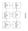
- the system 10 may include a plurality of subsystem (software and hardware) modules for calculating the performance of each component of a CW system.
- an "indoor unit calculator” module 12 may be used to calculate a performance for each indoor unit (i.e., component) of the CW system, for each allowable operating point for each of the indoor units of the CW system.
- a "primary CW pump” calculator module 14 may be used to model the performance of a primary CW pump at each allowable operating point.
- An “economizer calculator” module 16 may be used to model the performance of the heat exchanger economizer at every permissible operating point.
- a “cooling tower pump calculator” module 18 may be used to calculate the cooling tower pump performance at each allowable operating point for the cooling tower pump.
- a “cooling tower” calculator 20 is available to calculate the performance of the cooling tower of the CW system at each possible operating condition (i.e., considering temperature and rate of flow of water entering the cooling tower).
- a “chiller” calculator 22 is available to calculate the performance of a chiller unit of the CW system at each permissible operating point.
- a processing system 24 may be in communication with each of the components 12-22 and used to perform the optimizing and predictive calculations to meet the customer and/or system requirements at the prescribed WB.
- the WB set point and any other pertinent customer or system information 26 may be supplied to the processing system 26 as well as information about the load 28.
- permissible or “possible” operating point or condition, it is meant that particular range of operating points or range of operating conditions that the component may be operated at (or within), and that this range may be constrained in part by the output of one component of the CW system which is being supplied as an input to another one of the components of the CW system.
- the system 10 may use a plurality of sources of information for its optimizing and predictive capabilities. It will be appreciated that the predictive and optimizing features that the system 10 enables one to implement may enable the user to realize significant energy (and thus cost) savings with little or no reduction in the capabilities of the equipment that is being managed by the system 10. The system 10 further enables anticipated loading schedules and/or anticipated future ambient conditions to be taken into account in controlling the diverse CW components that are thermally managing data center components in a given environment.
- the indoor unit calculator module 12 may generate an indoor unit calculator data sheet 12a
- the primary CW pump calculator module 14 may generate a primary CW pump calculator data sheet 14a
- the economizer calculator module 16 may calculate an economizer calculator data sheet 16a
- the cooling tower pump calculator module 18 may generate a cooling tower pump data sheet 18a
- the cooling tower calculator module 20 may calculate a cooling tower data sheet 20a
- the chiller calculator module 22 may generate a chiller data sheet 22a.
- the data sheets 12a-22a each represent data or information on the performance of each of their associated components at every permissible operating point. However, if this information is available from a manufacture of a given component, then the system 10 may use the information provided from the component's manufacturer.
- the information provided from the data calculation sheets 12a-22a may be used by the system 10 in performing its optimizing and/or predictive calculation, and ultimately to "push" or override previously determined set points for the various components of the CW system to meet and/or maintain the WB set point and to meet load requirements.
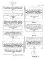
- a high level flowchart 100 shows various operations that the system 10 of Figure 1 may perform in its optimizing/control and/or predicting operations.
- the system 10 may obtain or create a performance data table (i.e., data sheet) for at least one component of the CW system.
- a performance data table i.e., data sheet
- most or all of the components of the CW system will have data tables generated therefor, such as described in connection with Figure 2 .
- These data tables provide the performance information for all possible operating points of the component and preferably take into account constraints on each component that may be imposed if it is receiving, as an input, the output from a different one or combination of CW components.
- the allowable or applicable operating points for each component of the CW system are defined.
- a defined range of operating points of a given component may in fact be narrower than what the component is actually able to operate at, depending on the constraints placed on the given component by other ones of the CW components or other factors.
- the system 10 produces a list of obtainable performance points for each individual indoor unit of the CW system that falls within user, customer and/or system allowable operating ranges on set points, or on allowable operating conditions for each CW system component.
- the system 10 determines/calculates the equivalent loop characteristics such as total gallons per minute (GPM) water flow, temperature differential and SCWT (supply chilled water temperature) for the CW system components covering the load.
- GPM total gallons per minute
- the system 10 balances the CW system components at some or all possible operating conditions given an ambient Wet Bulb (WB) input, to meet the load requirements of the load-covering CW components. This amounts to generating lists of every available balance point for the CW system that meets the user, customer and/or system requirements.
- WB Wet Bulb
- the lists generated at operation 110 may be used for optimization analysis. This may involve performing a wide variety of analyses which may include, but are not limited to, energy analysis, water analysis, humidification (or dehumidification) analysis, equipment staging analysis, economization analysis, maintenance analysis and total cost analysis for operating the CW system.
- analyses may include, but are not limited to, energy analysis, water analysis, humidification (or dehumidification) analysis, equipment staging analysis, economization analysis, maintenance analysis and total cost analysis for operating the CW system.
- the system 10 may optionally operate to "push" or override previously implemented set points onto appropriate CW components as needed to achieve the required customer, user or system desired optimization.
- the system 10 may optionally use the above analysis/analyses performed at operation 112 along with trend data of a load distribution and amplitude, and also along with Wet Bulb historical data for a given environment, to construct predictive optimization tables and/or set point maps for CW system components to proactively optimize the system to meet changing load and/or ambient requirements.
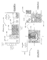
- Figure 4 shows a graph 200 to illustrate how significant differences in efficiencies can be achieved depending on relatively small changes in supply chilled water temperature (SCWT) and supply remote air temperature (SAT), while the current load and the wet bulb (WB) are held constant.
- SCWT chilled water temperature
- SAT supply remote air temperature
- WB wet bulb
- the graph 200 shows bars 202-210 which represent the percentage of energy savings (which is related to cost), relative to the worst possible operating condition at the current load and WB, that can be achieved with slight variations in the SCWT and the SAT.
- block 210 indicates that an energy savings of about 34% can be achieved if the SCWT is set to 58°F and the SAT is set to 67°F.
- block 202 indicates that the energy savings achievable would only be 11 % when the SCWT is set to 45°F and the SAT is set to 64°F.
- the graph 200 thus shows the user what types of energy savings may be achievable, with different changes to both the SCWT and the SAT, against current operating conditions (i.e., in this example with the load at 1200kW and WB at 62°F). It will be appreciated that the system 10 provides a powerful tool for helping the user determine if/how small changes in the SCWT and SAT can be expected to impact the overall energy savings, relative to a baseline set of conditions (e.g., relative to the current load and WB temperature).
- Figure 5 shows a chart 300 representing a specific property contour map that the system 10 may construct which helps to visually communicate (i.e, predict) how a user selected variable will change with respect to the WB and/or load changing.
- the user will have entered a range of permissible set points (or possibly just one set point) into the system 10, for each of the CW components that the system 10 is monitoring and/or controlling.
- the user selectable range is not to exceed the equipment manufacturer's specific equipment limitations.
- the user will have also specified specific set points or ranges of set points for the variables indicated by 302. These selected set points might include a range of SCWT temperatures that are permissible, a range of SAT that the user sets as permissible, etc.
- the chart 300 of Figure 5 may enable the system to visually represent a changing user selected variable of interest.
- the variable could be but is not limited to the total CW system energy consumption, types of energy savings compared to a baseline, SCWT, SAT set points, number of chillers operating, number of indoor units operating, etc. Every box in Figure 5 may be selectable by the user (such as by clicking on with a mouse or touching with a finger) to pull up additional charts or graphs, such as shown in Figure 4 , so that the user may compare different operating equipment scenarios to confirm the impact of their said imposed equipment operating range limitations.
- Figure 4 a graph such as Figure 4 may be provided that compares total energy consumption of multiple scenarios with each scenario operating at that specific load/WB temperature the user has selected.
- the scenarios shown may communicate the effect on total CW system energy consumption if different specific equipment set points and the specific variables 302 that the user has selected were to be implemented.
- Figure 6 illustrates a graph 400 that may be presented to the user that shows the user the direction that the system 10 is predicting the load and the WB temperature to take based on historical operating data.
- the system 10 may use historical data such as the load experienced during specific times of day, along with WB temperatures experienced at various times of day, to predict where the load and WB temperature is trending.
- the arrow 402 being the largest of the six arrows shown, indicates that the trend at the present time (represented by box 404) is predicted by the system 10 to be toward an increasing WB temperature and a decreasing load.
- Figure 7 illustrates a diagram 500 showing how variables for the load and the various components making up a CW system may be taken into account by the system 10 in determining balancing points for every possible permissible equipment configuration for the CW system.
- Figure 7 further illustrates how the actual component performance is used in closed loop fashion, via line 502, to update the various performance data tables based on actual measured data points.
- the theoretical system is calculated to balance within allowable user/equipment defined boundaries.
- a specific CW system balance result is examined and the appropriate equipment set points are then communicated to the respective pieces of equipment so as to allow the individual pieces of equipment to react in a similar fashion as to the theoretical model (desired balance).
Landscapes
- Engineering & Computer Science (AREA)
- Chemical & Material Sciences (AREA)
- Combustion & Propulsion (AREA)
- Mechanical Engineering (AREA)
- General Engineering & Computer Science (AREA)
- Physics & Mathematics (AREA)
- General Physics & Mathematics (AREA)
- Air Conditioning Control Device (AREA)
- Management, Administration, Business Operations System, And Electronic Commerce (AREA)
Priority Applications (1)
| Application Number | Priority Date | Filing Date | Title |
|---|---|---|---|
| PL14159341T PL2787296T3 (pl) | 2013-03-15 | 2014-03-13 | Sposób analizy energii i modelowania predykcyjnego komponentów systemu chłodniczego |
Applications Claiming Priority (1)
| Application Number | Priority Date | Filing Date | Title |
|---|---|---|---|
| US201361793872P | 2013-03-15 | 2013-03-15 |
Publications (3)
| Publication Number | Publication Date |
|---|---|
| EP2787296A2 true EP2787296A2 (de) | 2014-10-08 |
| EP2787296A3 EP2787296A3 (de) | 2015-07-08 |
| EP2787296B1 EP2787296B1 (de) | 2020-07-29 |
Family
ID=50439125
Family Applications (1)
| Application Number | Title | Priority Date | Filing Date |
|---|---|---|---|
| EP14159341.8A Active EP2787296B1 (de) | 2013-03-15 | 2014-03-13 | Verfahren zur Analyse von Energie und prädiktive Modellierung von Komponenten eines Kühlsystems |
Country Status (5)
| Country | Link |
|---|---|
| US (1) | US10408712B2 (de) |
| EP (1) | EP2787296B1 (de) |
| CN (1) | CN104049626B (de) |
| ES (1) | ES2824226T3 (de) |
| PL (1) | PL2787296T3 (de) |
Cited By (1)
| Publication number | Priority date | Publication date | Assignee | Title |
|---|---|---|---|---|
| WO2016132079A1 (fr) * | 2015-02-19 | 2016-08-25 | Electricite De France | Procédé de détection de déficiences d'un aéroréfrigérant d'une installation thermique en fonctionnement |
Families Citing this family (7)
| Publication number | Priority date | Publication date | Assignee | Title |
|---|---|---|---|---|
| FR2957171A1 (fr) * | 2010-03-04 | 2011-09-09 | Airbus Operations Sas | Methode et outil d'aide a la conception d'un aeronef utilisant un critere de disponibilite operationnelle |
| WO2017160346A1 (en) | 2016-03-16 | 2017-09-21 | Inertech Ip Llc | System and methods utilizing fluid coolers and chillers to perform in-series heat rejection and trim cooling |
| EP3538824B1 (de) | 2016-11-11 | 2025-08-20 | Stulz Air Technology Systems, Inc. | Doppelmasse-kühlpräzisionssystem |
| CN110287646B (zh) * | 2019-07-17 | 2023-02-28 | 招商局邮轮制造有限公司 | 一种串联冷却系统热平衡的计算方法 |
| CN112835340B (zh) * | 2020-12-31 | 2022-04-22 | 徐州科亚机电有限公司 | 一种自动检测电动车控制器的调测装置及方法 |
| CN114001438A (zh) * | 2021-09-15 | 2022-02-01 | 上海建工集团股份有限公司 | 一种空调系统供回水温差辨识方法 |
| CN119714954B (zh) * | 2024-11-28 | 2026-05-05 | 中国联合网络通信集团有限公司 | 一种冷却系统的测试方法、装置、设备及存储介质 |
Family Cites Families (99)
| Publication number | Priority date | Publication date | Assignee | Title |
|---|---|---|---|---|
| US3625020A (en) | 1970-06-30 | 1971-12-07 | Borg Warner | Electronic control for centrifugal chiller with pneumatic controls |
| US4282718A (en) | 1979-09-12 | 1981-08-11 | Borg-Warner Corporation | Evaporator inlet water temperature control system |
| US4287939A (en) | 1980-08-21 | 1981-09-08 | General Electric Company | Air conditioning control system with local and remote control capabilities |
| US4387368A (en) | 1980-12-03 | 1983-06-07 | Borg-Warner Corporation | Telemetry system for centrifugal water chilling systems |
| US4327559A (en) | 1981-03-02 | 1982-05-04 | Honeywell Inc. | Transport and chiller energy minimization for air conditioning systems |
| US4546618A (en) | 1984-09-20 | 1985-10-15 | Borg-Warner Corporation | Capacity control systems for inverter-driven centrifugal compressor based water chillers |
| US4715190A (en) | 1985-11-21 | 1987-12-29 | American Standard Inc. | Control and method for modulating the capacity of a temperature conditioning system |
| US5040377A (en) | 1989-11-21 | 1991-08-20 | Johnson Service Company | Cooling system with improved fan control and method |
| US5279458A (en) | 1991-08-12 | 1994-01-18 | Carrier Corporation | Network management control |
| US5195329A (en) * | 1991-11-12 | 1993-03-23 | Carrier Corporation | Automatic chiller plant balancing |
| US5355691A (en) | 1993-08-16 | 1994-10-18 | American Standard Inc. | Control method and apparatus for a centrifugal chiller using a variable speed impeller motor drive |
| US5537830A (en) | 1994-11-28 | 1996-07-23 | American Standard Inc. | Control method and appartus for a centrifugal chiller using a variable speed impeller motor drive |
| US5600960A (en) | 1995-11-28 | 1997-02-11 | American Standard Inc. | Near optimization of cooling tower condenser water |
| US5669225A (en) | 1996-06-27 | 1997-09-23 | York International Corporation | Variable speed control of a centrifugal chiller using fuzzy logic |
| US6257007B1 (en) | 1998-11-19 | 2001-07-10 | Thomas Hartman | Method of control of cooling system condenser fans and cooling tower fans and pumps |
| US6202431B1 (en) | 1999-01-15 | 2001-03-20 | York International Corporation | Adaptive hot gas bypass control for centrifugal chillers |
| US6085532A (en) * | 1999-02-05 | 2000-07-11 | American Standard Inc. | Chiller capacity control with variable chilled water flow compensation |
| US6185946B1 (en) | 1999-05-07 | 2001-02-13 | Thomas B. Hartman | System for sequencing chillers in a loop cooling plant and other systems that employ all variable-speed units |
| DE10122491A1 (de) * | 2001-05-10 | 2002-11-14 | Bayer Ag | Vorrichtung und Verfahren zur parallelen Durchführung von Experimenten |
| US6786056B2 (en) | 2002-08-02 | 2004-09-07 | Hewlett-Packard Development Company, L.P. | Cooling system with evaporators distributed in parallel |
| US6938433B2 (en) | 2002-08-02 | 2005-09-06 | Hewlett-Packard Development Company, Lp. | Cooling system with evaporators distributed in series |
| US20040020225A1 (en) | 2002-08-02 | 2004-02-05 | Patel Chandrakant D. | Cooling system |
| US6679076B1 (en) | 2003-04-17 | 2004-01-20 | American Standard International Inc. | Centrifugal chiller with high voltage unit-mounted starters |
| US6955302B2 (en) | 2003-11-13 | 2005-10-18 | York International Corporation | Remote monitoring diagnostics |
| US7225054B2 (en) | 2003-12-02 | 2007-05-29 | Honeywell International Inc. | Controller with programmable service event display mode |
| US7881910B2 (en) | 2005-05-02 | 2011-02-01 | American Power Conversion Corporation | Methods and systems for managing facility power and cooling |
| US7885795B2 (en) | 2005-05-02 | 2011-02-08 | American Power Conversion Corporation | Methods and systems for managing facility power and cooling |
| US7596476B2 (en) | 2005-05-02 | 2009-09-29 | American Power Conversion Corporation | Methods and systems for managing facility power and cooling |
| US7315448B1 (en) | 2005-06-01 | 2008-01-01 | Hewlett-Packard Development Company, L.P. | Air-cooled heat generating device airflow control system |
| US7894943B2 (en) | 2005-06-30 | 2011-02-22 | Sloup Charles J | Real-time global optimization of building setpoints and sequence of operation |
| US8099178B2 (en) | 2005-08-22 | 2012-01-17 | Trane International Inc. | Building automation system facilitating user customization |
| US8055387B2 (en) | 2005-08-22 | 2011-11-08 | Trane International Inc. | Building automation system data management |
| US7917232B2 (en) | 2005-08-22 | 2011-03-29 | Trane International Inc. | Building automation system data management |
| US7870090B2 (en) | 2005-08-22 | 2011-01-11 | Trane International Inc. | Building automation system date management |
| US8050801B2 (en) | 2005-08-22 | 2011-11-01 | Trane International Inc. | Dynamically extensible and automatically configurable building automation system and architecture |
| US7904186B2 (en) | 2005-08-22 | 2011-03-08 | Trane International, Inc. | Building automation system facilitating user customization |
| US8055386B2 (en) | 2005-08-22 | 2011-11-08 | Trane International Inc. | Building automation system data management |
| US8024054B2 (en) | 2005-08-22 | 2011-09-20 | Trane International, Inc. | Building automation system facilitating user customization |
| US8672732B2 (en) | 2006-01-19 | 2014-03-18 | Schneider Electric It Corporation | Cooling system and method |
| US7365973B2 (en) | 2006-01-19 | 2008-04-29 | American Power Conversion Corporation | Cooling system and method |
| US20090012651A1 (en) | 2006-04-12 | 2009-01-08 | Alexander Lifson | Including Energy Price in Optimizing Refrigerant System Operation |
| US8322155B2 (en) | 2006-08-15 | 2012-12-04 | American Power Conversion Corporation | Method and apparatus for cooling |
| US8327656B2 (en) | 2006-08-15 | 2012-12-11 | American Power Conversion Corporation | Method and apparatus for cooling |
| US20080041077A1 (en) | 2006-08-15 | 2008-02-21 | American Power Conversion Corporation | Method and apparatus for cooling |
| US9568206B2 (en) | 2006-08-15 | 2017-02-14 | Schneider Electric It Corporation | Method and apparatus for cooling |
| US7890215B2 (en) * | 2006-12-22 | 2011-02-15 | Duncan Scot M | Optimized control system for cooling systems |
| US20080160902A1 (en) | 2006-12-29 | 2008-07-03 | Stulz Air Technology Systems, Inc. | Apparatus, system and method for providing high efficiency air conditioning |
| US20100041327A1 (en) | 2006-12-29 | 2010-02-18 | Stulz Air Technology Systems, Inc. | Apparatus, system and method for air conditioning using fans located under flooring |
| US7788941B2 (en) | 2007-06-14 | 2010-09-07 | International Business Machines Corporation | Cooling system and method utilizing thermal capacitor unit(s) for enhanced thermal energy transfer efficiency |
| US20090030554A1 (en) | 2007-07-26 | 2009-01-29 | Bean Jr John H | Cooling control device and method |
| US7757506B2 (en) | 2007-11-19 | 2010-07-20 | International Business Machines Corporation | System and method for facilitating cooling of a liquid-cooled electronics rack |
| US7963119B2 (en) | 2007-11-26 | 2011-06-21 | International Business Machines Corporation | Hybrid air and liquid coolant conditioning unit for facilitating cooling of one or more electronics racks of a data center |
| US7832925B2 (en) | 2007-12-05 | 2010-11-16 | International Business Machines Corporation | Apparatus and method for simulating heated airflow exhaust of an electronics subsystem, electronics rack or row of electronics racks |
| US8553416B1 (en) | 2007-12-21 | 2013-10-08 | Exaflop Llc | Electronic device cooling system with storage |
| US7808780B2 (en) | 2008-02-28 | 2010-10-05 | International Business Machines Corporation | Variable flow computer cooling system for a data center and method of operation |
| US7791882B2 (en) | 2008-04-23 | 2010-09-07 | International Business Machines Corporation | Energy efficient apparatus and method for cooling an electronics rack |
| US20090211773A1 (en) | 2008-05-02 | 2009-08-27 | Gooch Rodger J | Fire suppression system and associated methods |
| US8973379B2 (en) | 2008-07-25 | 2015-03-10 | Hill Phoenix, Inc. | Refrigeration control systems and methods for modular compact chiller units |
| CN201262697Y (zh) | 2008-08-15 | 2009-06-24 | 特灵空调系统(江苏)有限公司 | 冷水机组主机的控制器 |
| US20100070089A1 (en) | 2008-09-15 | 2010-03-18 | Johnson Controls Technology Company | Hvac controller user interfaces |
| US8078326B2 (en) | 2008-09-19 | 2011-12-13 | Johnson Controls Technology Company | HVAC system controller configuration |
| US7990710B2 (en) | 2008-12-31 | 2011-08-02 | Vs Acquisition Co. Llc | Data center |
| US8560677B2 (en) * | 2009-02-13 | 2013-10-15 | Schneider Electric It Corporation | Data center control |
| US9519517B2 (en) | 2009-02-13 | 2016-12-13 | Schneider Electtic It Corporation | Data center control |
| JP5404132B2 (ja) | 2009-03-30 | 2014-01-29 | 三菱重工業株式会社 | 熱源システムおよびその制御方法 |
| JP5308214B2 (ja) | 2009-03-31 | 2013-10-09 | 三菱重工業株式会社 | ターボ冷凍機およびその制御方法 |
| US9811097B2 (en) | 2009-04-16 | 2017-11-07 | Darpa | Environmental control of liquid cooled electronics |
| US8145363B2 (en) | 2009-05-28 | 2012-03-27 | American Power Conversion Corporation | Systems and methods for controlling load dynamics in a pumped refrigerant cooling system |
| US8031468B2 (en) | 2009-06-03 | 2011-10-04 | American Power Conversion Corporation | Hot aisle containment cooling unit and method for cooling |
| US9196009B2 (en) | 2009-06-22 | 2015-11-24 | Johnson Controls Technology Company | Systems and methods for detecting changes in energy usage in a building |
| US8600556B2 (en) | 2009-06-22 | 2013-12-03 | Johnson Controls Technology Company | Smart building manager |
| US8788097B2 (en) | 2009-06-22 | 2014-07-22 | Johnson Controls Technology Company | Systems and methods for using rule-based fault detection in a building management system |
| US8532839B2 (en) | 2009-06-22 | 2013-09-10 | Johnson Controls Technology Company | Systems and methods for statistical control and fault detection in a building management system |
| US9753455B2 (en) | 2009-06-22 | 2017-09-05 | Johnson Controls Technology Company | Building management system with fault analysis |
| US8731724B2 (en) | 2009-06-22 | 2014-05-20 | Johnson Controls Technology Company | Automated fault detection and diagnostics in a building management system |
| US9286582B2 (en) | 2009-06-22 | 2016-03-15 | Johnson Controls Technology Company | Systems and methods for detecting changes in energy usage in a building |
| GB2471834A (en) | 2009-07-09 | 2011-01-19 | Hewlett Packard Development Co | Cooling Module with a Chiller Unit, Flow Control, and Able to Utilise Free Cooling |
| EP3379178B1 (de) | 2009-07-31 | 2023-12-13 | Johnson Controls Tyco IP Holdings LLP | Kühlmittelkontrollverfahren |
| US8583290B2 (en) | 2009-09-09 | 2013-11-12 | International Business Machines Corporation | Cooling system and method minimizing power consumption in cooling liquid-cooled electronics racks |
| US7907406B1 (en) | 2009-09-28 | 2011-03-15 | International Business Machines Corporation | System and method for standby mode cooling of a liquid-cooled electronics rack |
| JP2011122812A (ja) * | 2009-10-20 | 2011-06-23 | Johnson Controls Technology Co | チラー制御用3次元サージマップのコンピュータ化された生成及び使用を与えるコントローラ及び方法 |
| JP5404333B2 (ja) | 2009-11-13 | 2014-01-29 | 三菱重工業株式会社 | 熱源システム |
| US8783049B2 (en) | 2009-12-23 | 2014-07-22 | Liebert Corporation | Cooling system with indirect humidity determination |
| US8820113B2 (en) | 2009-12-31 | 2014-09-02 | Facebook, Inc. | Cooling computing devices in a data center with ambient air cooled using heat from the computing devices |
| RU2583771C2 (ru) | 2010-01-24 | 2016-05-10 | Ой Халтон Груп Лтд. | Устройства, системы и способы с использованием охлаждающих балок |
| WO2011100255A2 (en) | 2010-02-09 | 2011-08-18 | Johnson Controls Technology Company | Systems and methods for measuring and verifying energy savings in buildings |
| US20110215645A1 (en) | 2010-03-05 | 2011-09-08 | Active Power, Inc. | Containerized continuous power system and method |
| US20110225997A1 (en) | 2010-03-17 | 2011-09-22 | Mechanical Service & Systems, Inc. | Systems and methods for cooling computer data centers |
| US8789384B2 (en) | 2010-03-23 | 2014-07-29 | International Business Machines Corporation | Computer rack cooling using independently-controlled flow of coolants through a dual-section heat exchanger |
| US8974274B2 (en) | 2010-04-16 | 2015-03-10 | Google Inc. | Evaporative induction cooling |
| US20110265982A1 (en) | 2010-04-29 | 2011-11-03 | International Business Machines Corporation | Controlling coolant flow to multiple cooling units in a computer system |
| US8144467B2 (en) | 2010-05-26 | 2012-03-27 | International Business Machines Corporation | Dehumidifying and re-humidifying apparatus and method for an electronics rack |
| US7905096B1 (en) | 2010-05-26 | 2011-03-15 | International Business Machines Corporation | Dehumidifying and re-humidifying air cooling for an electronics rack |
| US8184436B2 (en) | 2010-06-29 | 2012-05-22 | International Business Machines Corporation | Liquid-cooled electronics rack with immersion-cooled electronic subsystems |
| NL2005138C2 (en) | 2010-07-23 | 2012-01-24 | Deerns Raadgevende Ingenieurs B V | Apparatus and method for cooling a substantially closed space. |
| US8514575B2 (en) | 2010-11-16 | 2013-08-20 | International Business Machines Corporation | Multimodal cooling apparatus for an electronic system |
| US8554390B2 (en) | 2010-11-16 | 2013-10-08 | International Business Machines Corporation | Free cooling solution for a containerized data center |
| US8274790B2 (en) | 2010-11-16 | 2012-09-25 | International Business Machines Corporation | Automatically reconfigurable liquid-cooling apparatus for an electronics rack |
| AU2011355562B2 (en) | 2011-01-11 | 2017-03-30 | Schneider Electric It Corporation | Cooling unit and method |
-
2014
- 2014-03-11 US US14/204,677 patent/US10408712B2/en active Active
- 2014-03-13 EP EP14159341.8A patent/EP2787296B1/de active Active
- 2014-03-13 ES ES14159341T patent/ES2824226T3/es active Active
- 2014-03-13 PL PL14159341T patent/PL2787296T3/pl unknown
- 2014-03-17 CN CN201410098126.7A patent/CN104049626B/zh active Active
Non-Patent Citations (1)
| Title |
|---|
| None |
Cited By (3)
| Publication number | Priority date | Publication date | Assignee | Title |
|---|---|---|---|---|
| WO2016132079A1 (fr) * | 2015-02-19 | 2016-08-25 | Electricite De France | Procédé de détection de déficiences d'un aéroréfrigérant d'une installation thermique en fonctionnement |
| FR3033036A1 (fr) * | 2015-02-19 | 2016-08-26 | Electricite De France | Procede de detection de deficiences d'un aerorefrigerant d'une installation thermique en fonctionnement |
| US10393453B2 (en) | 2015-02-19 | 2019-08-27 | Electricite De France | Method for detecting deficiencies in a cooling tower of a thermal facility in operation |
Also Published As
| Publication number | Publication date |
|---|---|
| US10408712B2 (en) | 2019-09-10 |
| PL2787296T3 (pl) | 2021-02-08 |
| US20140278245A1 (en) | 2014-09-18 |
| CN104049626A (zh) | 2014-09-17 |
| ES2824226T3 (es) | 2021-05-11 |
| CN104049626B (zh) | 2017-06-23 |
| EP2787296A3 (de) | 2015-07-08 |
| EP2787296B1 (de) | 2020-07-29 |
Similar Documents
| Publication | Publication Date | Title |
|---|---|---|
| EP2787296B1 (de) | Verfahren zur Analyse von Energie und prädiktive Modellierung von Komponenten eines Kühlsystems | |
| CN106066077B (zh) | 具有预测成本优化的hvac控制器 | |
| CN109800066B (zh) | 一种数据中心节能调度方法及系统 | |
| US10461954B2 (en) | Intelligent equipment sequencing | |
| US9638435B2 (en) | Systems and methods for optimizing the efficiency of HVAC systems | |
| EP2954377B1 (de) | Cloud-aktiviertes gebäudeautomatisierungssystem | |
| Dai et al. | A decentralized algorithm for optimal distribution in HVAC systems | |
| US20170031962A1 (en) | Systems and methods for visualizing equipment utilization in a central plant | |
| US20200125045A1 (en) | Hvac controller with predictive cost optimization | |
| CN109556236B (zh) | 能效控制方法和装置 | |
| US20120197828A1 (en) | Energy Saving Control for Data Center | |
| CN111306728B (zh) | 空调系统风量调控的方法、装置及计算机设备 | |
| KR102240390B1 (ko) | 복합밸브 및 팬코일 유닛을 통합 제어하는 스마트 통합제어 시스템 및 이의 동작방법 | |
| Huang et al. | Optimization of the water-cooled chiller plant system operation | |
| US20220373206A1 (en) | Chiller controller for optimized efficiency | |
| Conficoni et al. | HPC cooling: a flexible modeling tool for effective design and management | |
| CN105423492A (zh) | 机房监测系统及方法 | |
| US20140246909A1 (en) | System and method for balancing supply and demand of energy on an electrical grid | |
| US20200348635A1 (en) | Newton-based extremum-seeking control system | |
| CN108731222A (zh) | 一种机房空调控制方法及装置 | |
| KR102090281B1 (ko) | 데이터 센터 건물의 냉방 에너지 성능 평가 시스템 및 방법 | |
| Yu et al. | Chiller system performance benchmark by data envelopment analysis | |
| WO2024112687A1 (en) | Cooling system with in-series high-temperature and low-temperature circuits | |
| US11408626B2 (en) | Central plant control system with dynamic computation reduction | |
| JP2017028764A (ja) | 需要電力制御装置および需要電力制御方法 |
Legal Events
| Date | Code | Title | Description |
|---|---|---|---|
| PUAI | Public reference made under article 153(3) epc to a published international application that has entered the european phase |
Free format text: ORIGINAL CODE: 0009012 |
|
| 17P | Request for examination filed |
Effective date: 20140313 |
|
| AK | Designated contracting states |
Kind code of ref document: A2 Designated state(s): AL AT BE BG CH CY CZ DE DK EE ES FI FR GB GR HR HU IE IS IT LI LT LU LV MC MK MT NL NO PL PT RO RS SE SI SK SM TR |
|
| AX | Request for extension of the european patent |
Extension state: BA ME |
|
| PUAL | Search report despatched |
Free format text: ORIGINAL CODE: 0009013 |
|
| AK | Designated contracting states |
Kind code of ref document: A3 Designated state(s): AL AT BE BG CH CY CZ DE DK EE ES FI FR GB GR HR HU IE IS IT LI LT LU LV MC MK MT NL NO PL PT RO RS SE SI SK SM TR |
|
| AX | Request for extension of the european patent |
Extension state: BA ME |
|
| RIC1 | Information provided on ipc code assigned before grant |
Ipc: H05K 7/20 20060101ALI20150602BHEP Ipc: F28F 1/00 20060101ALI20150602BHEP Ipc: F24F 11/00 20060101AFI20150602BHEP |
|
| R17P | Request for examination filed (corrected) |
Effective date: 20160108 |
|
| RBV | Designated contracting states (corrected) |
Designated state(s): AL AT BE BG CH CY CZ DE DK EE ES FI FR GB GR HR HU IE IS IT LI LT LU LV MC MK MT NL NO PL PT RO RS SE SI SK SM TR |
|
| RIC1 | Information provided on ipc code assigned before grant |
Ipc: F28F 1/00 20060101ALI20171010BHEP Ipc: F24F 11/00 20060101AFI20171010BHEP Ipc: H05K 7/20 20060101ALI20171010BHEP |
|
| RAP1 | Party data changed (applicant data changed or rights of an application transferred) |
Owner name: VERTIV CORPORATION |
|
| GRAP | Despatch of communication of intention to grant a patent |
Free format text: ORIGINAL CODE: EPIDOSNIGR1 |
|
| STAA | Information on the status of an ep patent application or granted ep patent |
Free format text: STATUS: GRANT OF PATENT IS INTENDED |
|
| INTG | Intention to grant announced |
Effective date: 20200219 |
|
| GRAS | Grant fee paid |
Free format text: ORIGINAL CODE: EPIDOSNIGR3 |
|
| GRAA | (expected) grant |
Free format text: ORIGINAL CODE: 0009210 |
|
| STAA | Information on the status of an ep patent application or granted ep patent |
Free format text: STATUS: THE PATENT HAS BEEN GRANTED |
|
| AK | Designated contracting states |
Kind code of ref document: B1 Designated state(s): AL AT BE BG CH CY CZ DE DK EE ES FI FR GB GR HR HU IE IS IT LI LT LU LV MC MK MT NL NO PL PT RO RS SE SI SK SM TR |
|
| REG | Reference to a national code |
Ref country code: CH Ref legal event code: EP |
|
| REG | Reference to a national code |
Ref country code: DE Ref legal event code: R096 Ref document number: 602014068204 Country of ref document: DE |
|
| REG | Reference to a national code |
Ref country code: AT Ref legal event code: REF Ref document number: 1296255 Country of ref document: AT Kind code of ref document: T Effective date: 20200815 |
|
| REG | Reference to a national code |
Ref country code: IE Ref legal event code: FG4D |
|
| REG | Reference to a national code |
Ref country code: NL Ref legal event code: FP |
|
| REG | Reference to a national code |
Ref country code: LT Ref legal event code: MG4D |
|
| REG | Reference to a national code |
Ref country code: AT Ref legal event code: MK05 Ref document number: 1296255 Country of ref document: AT Kind code of ref document: T Effective date: 20200729 |
|
| PG25 | Lapsed in a contracting state [announced via postgrant information from national office to epo] |
Ref country code: BG Free format text: LAPSE BECAUSE OF FAILURE TO SUBMIT A TRANSLATION OF THE DESCRIPTION OR TO PAY THE FEE WITHIN THE PRESCRIBED TIME-LIMIT Effective date: 20201029 Ref country code: SE Free format text: LAPSE BECAUSE OF FAILURE TO SUBMIT A TRANSLATION OF THE DESCRIPTION OR TO PAY THE FEE WITHIN THE PRESCRIBED TIME-LIMIT Effective date: 20200729 Ref country code: LT Free format text: LAPSE BECAUSE OF FAILURE TO SUBMIT A TRANSLATION OF THE DESCRIPTION OR TO PAY THE FEE WITHIN THE PRESCRIBED TIME-LIMIT Effective date: 20200729 Ref country code: HR Free format text: LAPSE BECAUSE OF FAILURE TO SUBMIT A TRANSLATION OF THE DESCRIPTION OR TO PAY THE FEE WITHIN THE PRESCRIBED TIME-LIMIT Effective date: 20200729 Ref country code: GR Free format text: LAPSE BECAUSE OF FAILURE TO SUBMIT A TRANSLATION OF THE DESCRIPTION OR TO PAY THE FEE WITHIN THE PRESCRIBED TIME-LIMIT Effective date: 20201030 Ref country code: FI Free format text: LAPSE BECAUSE OF FAILURE TO SUBMIT A TRANSLATION OF THE DESCRIPTION OR TO PAY THE FEE WITHIN THE PRESCRIBED TIME-LIMIT Effective date: 20200729 Ref country code: PT Free format text: LAPSE BECAUSE OF FAILURE TO SUBMIT A TRANSLATION OF THE DESCRIPTION OR TO PAY THE FEE WITHIN THE PRESCRIBED TIME-LIMIT Effective date: 20201130 Ref country code: AT Free format text: LAPSE BECAUSE OF FAILURE TO SUBMIT A TRANSLATION OF THE DESCRIPTION OR TO PAY THE FEE WITHIN THE PRESCRIBED TIME-LIMIT Effective date: 20200729 Ref country code: NO Free format text: LAPSE BECAUSE OF FAILURE TO SUBMIT A TRANSLATION OF THE DESCRIPTION OR TO PAY THE FEE WITHIN THE PRESCRIBED TIME-LIMIT Effective date: 20201029 |
|
| PG25 | Lapsed in a contracting state [announced via postgrant information from national office to epo] |
Ref country code: RS Free format text: LAPSE BECAUSE OF FAILURE TO SUBMIT A TRANSLATION OF THE DESCRIPTION OR TO PAY THE FEE WITHIN THE PRESCRIBED TIME-LIMIT Effective date: 20200729 Ref country code: LV Free format text: LAPSE BECAUSE OF FAILURE TO SUBMIT A TRANSLATION OF THE DESCRIPTION OR TO PAY THE FEE WITHIN THE PRESCRIBED TIME-LIMIT Effective date: 20200729 Ref country code: IS Free format text: LAPSE BECAUSE OF FAILURE TO SUBMIT A TRANSLATION OF THE DESCRIPTION OR TO PAY THE FEE WITHIN THE PRESCRIBED TIME-LIMIT Effective date: 20201129 |
|
| PG25 | Lapsed in a contracting state [announced via postgrant information from national office to epo] |
Ref country code: EE Free format text: LAPSE BECAUSE OF FAILURE TO SUBMIT A TRANSLATION OF THE DESCRIPTION OR TO PAY THE FEE WITHIN THE PRESCRIBED TIME-LIMIT Effective date: 20200729 Ref country code: CZ Free format text: LAPSE BECAUSE OF FAILURE TO SUBMIT A TRANSLATION OF THE DESCRIPTION OR TO PAY THE FEE WITHIN THE PRESCRIBED TIME-LIMIT Effective date: 20200729 Ref country code: DK Free format text: LAPSE BECAUSE OF FAILURE TO SUBMIT A TRANSLATION OF THE DESCRIPTION OR TO PAY THE FEE WITHIN THE PRESCRIBED TIME-LIMIT Effective date: 20200729 Ref country code: SM Free format text: LAPSE BECAUSE OF FAILURE TO SUBMIT A TRANSLATION OF THE DESCRIPTION OR TO PAY THE FEE WITHIN THE PRESCRIBED TIME-LIMIT Effective date: 20200729 Ref country code: RO Free format text: LAPSE BECAUSE OF FAILURE TO SUBMIT A TRANSLATION OF THE DESCRIPTION OR TO PAY THE FEE WITHIN THE PRESCRIBED TIME-LIMIT Effective date: 20200729 |
|
| REG | Reference to a national code |
Ref country code: DE Ref legal event code: R097 Ref document number: 602014068204 Country of ref document: DE |
|
| REG | Reference to a national code |
Ref country code: ES Ref legal event code: FG2A Ref document number: 2824226 Country of ref document: ES Kind code of ref document: T3 Effective date: 20210511 |
|
| PG25 | Lapsed in a contracting state [announced via postgrant information from national office to epo] |
Ref country code: AL Free format text: LAPSE BECAUSE OF FAILURE TO SUBMIT A TRANSLATION OF THE DESCRIPTION OR TO PAY THE FEE WITHIN THE PRESCRIBED TIME-LIMIT Effective date: 20200729 |
|
| PLBE | No opposition filed within time limit |
Free format text: ORIGINAL CODE: 0009261 |
|
| STAA | Information on the status of an ep patent application or granted ep patent |
Free format text: STATUS: NO OPPOSITION FILED WITHIN TIME LIMIT |
|
| PG25 | Lapsed in a contracting state [announced via postgrant information from national office to epo] |
Ref country code: SK Free format text: LAPSE BECAUSE OF FAILURE TO SUBMIT A TRANSLATION OF THE DESCRIPTION OR TO PAY THE FEE WITHIN THE PRESCRIBED TIME-LIMIT Effective date: 20200729 |
|
| 26N | No opposition filed |
Effective date: 20210430 |
|
| PG25 | Lapsed in a contracting state [announced via postgrant information from national office to epo] |
Ref country code: SI Free format text: LAPSE BECAUSE OF FAILURE TO SUBMIT A TRANSLATION OF THE DESCRIPTION OR TO PAY THE FEE WITHIN THE PRESCRIBED TIME-LIMIT Effective date: 20200729 |
|
| PG25 | Lapsed in a contracting state [announced via postgrant information from national office to epo] |
Ref country code: MC Free format text: LAPSE BECAUSE OF FAILURE TO SUBMIT A TRANSLATION OF THE DESCRIPTION OR TO PAY THE FEE WITHIN THE PRESCRIBED TIME-LIMIT Effective date: 20200729 |
|
| REG | Reference to a national code |
Ref country code: CH Ref legal event code: PL |
|
| REG | Reference to a national code |
Ref country code: BE Ref legal event code: MM Effective date: 20210331 |
|
| PG25 | Lapsed in a contracting state [announced via postgrant information from national office to epo] |
Ref country code: CH Free format text: LAPSE BECAUSE OF NON-PAYMENT OF DUE FEES Effective date: 20210331 Ref country code: LU Free format text: LAPSE BECAUSE OF NON-PAYMENT OF DUE FEES Effective date: 20210313 Ref country code: LI Free format text: LAPSE BECAUSE OF NON-PAYMENT OF DUE FEES Effective date: 20210331 |
|
| PG25 | Lapsed in a contracting state [announced via postgrant information from national office to epo] |
Ref country code: BE Free format text: LAPSE BECAUSE OF NON-PAYMENT OF DUE FEES Effective date: 20210331 |
|
| PG25 | Lapsed in a contracting state [announced via postgrant information from national office to epo] |
Ref country code: HU Free format text: LAPSE BECAUSE OF FAILURE TO SUBMIT A TRANSLATION OF THE DESCRIPTION OR TO PAY THE FEE WITHIN THE PRESCRIBED TIME-LIMIT; INVALID AB INITIO Effective date: 20140313 |
|
| PG25 | Lapsed in a contracting state [announced via postgrant information from national office to epo] |
Ref country code: CY Free format text: LAPSE BECAUSE OF FAILURE TO SUBMIT A TRANSLATION OF THE DESCRIPTION OR TO PAY THE FEE WITHIN THE PRESCRIBED TIME-LIMIT Effective date: 20200729 |
|
| P01 | Opt-out of the competence of the unified patent court (upc) registered |
Effective date: 20230621 |
|
| PG25 | Lapsed in a contracting state [announced via postgrant information from national office to epo] |
Ref country code: MK Free format text: LAPSE BECAUSE OF FAILURE TO SUBMIT A TRANSLATION OF THE DESCRIPTION OR TO PAY THE FEE WITHIN THE PRESCRIBED TIME-LIMIT Effective date: 20200729 |
|
| PG25 | Lapsed in a contracting state [announced via postgrant information from national office to epo] |
Ref country code: MT Free format text: LAPSE BECAUSE OF FAILURE TO SUBMIT A TRANSLATION OF THE DESCRIPTION OR TO PAY THE FEE WITHIN THE PRESCRIBED TIME-LIMIT Effective date: 20200729 |
|
| PGFP | Annual fee paid to national office [announced via postgrant information from national office to epo] |
Ref country code: ES Payment date: 20250401 Year of fee payment: 12 |
|
| PG25 | Lapsed in a contracting state [announced via postgrant information from national office to epo] |
Ref country code: TR Free format text: LAPSE BECAUSE OF FAILURE TO SUBMIT A TRANSLATION OF THE DESCRIPTION OR TO PAY THE FEE WITHIN THE PRESCRIBED TIME-LIMIT Effective date: 20200729 |
|
| PGFP | Annual fee paid to national office [announced via postgrant information from national office to epo] |
Ref country code: GB Payment date: 20260327 Year of fee payment: 13 |
|
| PGFP | Annual fee paid to national office [announced via postgrant information from national office to epo] |
Ref country code: IE Payment date: 20260327 Year of fee payment: 13 Ref country code: DE Payment date: 20260327 Year of fee payment: 13 |
|
| PGFP | Annual fee paid to national office [announced via postgrant information from national office to epo] |
Ref country code: IT Payment date: 20260319 Year of fee payment: 13 |
|
| PGFP | Annual fee paid to national office [announced via postgrant information from national office to epo] |
Ref country code: NL Payment date: 20260326 Year of fee payment: 13 |
|
| PGFP | Annual fee paid to national office [announced via postgrant information from national office to epo] |
Ref country code: FR Payment date: 20260325 Year of fee payment: 13 |
|
| PGFP | Annual fee paid to national office [announced via postgrant information from national office to epo] |
Ref country code: PL Payment date: 20260219 Year of fee payment: 13 |