EP2786784A2 - Stabilisierungssystem zum Stützen eines Fahrzeugs oder dergleichen bei Unfallrettungsoperationen - Google Patents
Stabilisierungssystem zum Stützen eines Fahrzeugs oder dergleichen bei Unfallrettungsoperationen Download PDFInfo
- Publication number
- EP2786784A2 EP2786784A2 EP14382132.0A EP14382132A EP2786784A2 EP 2786784 A2 EP2786784 A2 EP 2786784A2 EP 14382132 A EP14382132 A EP 14382132A EP 2786784 A2 EP2786784 A2 EP 2786784A2
- Authority
- EP
- European Patent Office
- Prior art keywords
- fact
- stabilisation system
- piston
- vehicle
- coupled
- Prior art date
- Legal status (The legal status is an assumption and is not a legal conclusion. Google has not performed a legal analysis and makes no representation as to the accuracy of the status listed.)
- Granted
Links
Images





Classifications
-
- F—MECHANICAL ENGINEERING; LIGHTING; HEATING; WEAPONS; BLASTING
- F16—ENGINEERING ELEMENTS AND UNITS; GENERAL MEASURES FOR PRODUCING AND MAINTAINING EFFECTIVE FUNCTIONING OF MACHINES OR INSTALLATIONS; THERMAL INSULATION IN GENERAL
- F16M—FRAMES, CASINGS OR BEDS OF ENGINES, MACHINES OR APPARATUS, NOT SPECIFIC TO ENGINES, MACHINES OR APPARATUS PROVIDED FOR ELSEWHERE; STANDS; SUPPORTS
- F16M11/00—Stands or trestles as supports for apparatus or articles placed thereon ; Stands for scientific apparatus such as gravitational force meters
-
- A—HUMAN NECESSITIES
- A62—LIFE-SAVING; FIRE-FIGHTING
- A62B—DEVICES, APPARATUS OR METHODS FOR LIFE-SAVING
- A62B3/00—Devices or single parts for facilitating escape from buildings or the like, e.g. protection shields, protection screens; Portable devices for preventing smoke penetrating into distinct parts of buildings
- A62B3/005—Rescue tools with forcing action
-
- A—HUMAN NECESSITIES
- A62—LIFE-SAVING; FIRE-FIGHTING
- A62B—DEVICES, APPARATUS OR METHODS FOR LIFE-SAVING
- A62B99/00—Subject matter not provided for in other groups of this subclass
-
- B—PERFORMING OPERATIONS; TRANSPORTING
- B60—VEHICLES IN GENERAL
- B60S—SERVICING, CLEANING, REPAIRING, SUPPORTING, LIFTING, OR MANOEUVRING OF VEHICLES, NOT OTHERWISE PROVIDED FOR
- B60S13/00—Vehicle-manoeuvring devices separate from the vehicle
Definitions
- the invention proposes the development of a stabilisation system that includes a stabiliser device, which is particularly suitable for supporting a vehicle or the like in the event of the vehicle being involved in an accident while rescuing the occupants from inside the vehicle, where in accordance with established protocols the vehicle must be prevented from moving both horizontally and vertically in order not to cause further harm to the occupants.
- a stabiliser device which is particularly suitable for supporting a vehicle or the like in the event of the vehicle being involved in an accident while rescuing the occupants from inside the vehicle, where in accordance with established protocols the vehicle must be prevented from moving both horizontally and vertically in order not to cause further harm to the occupants.
- the invention herein has been developed to provide a stabilisation system that is considered a novelty within the field of application and resolves the aforementioned drawbacks, further providing other additional advantages that will be apparent from the description detailed hereinafter.
- a stabilising system for supporting a vehicle or the like, which includes a stabiliser device that is characterised by the fact that it comprises an internally-hollow elongated body, including a cylinder on the inside coupled to an axially extendible piston through the elongated body that is connected to at least one support region intended to be in contact with a region or surface of the vehicle to be supported, wherein height adjustment means are provided for adjusting the height between at least said support region and the movable piston. Locking means are further provided for securing the position of the piston relative to the cylinder, and positioning means to position the piston relative to the elongated body.
- the height adjustment means can be used to position the stabiliser device at a predetermined height at any time.
- the height adjustment means have an exteriorly-threaded elongated rod which is superiorly connected to the support region, wherein said rod can be coupled to a threaded orifice on a, preferably flat, portion affixed to the piston extending axially upwards and downwards.
- the threaded orifice mentioned above consists of a threaded nut.
- the stabiliser device may have two support regions, each provided with height adjustment means for adjusting the height between each of the support regions and the movable piston, allowing use of the device in a wide range of vehicles of varying sizes, from motor vehicles to all-terrain vehicles, etc.
- the elongated rod and the support region may be joined together by means of a ball joint.
- the support region can be positioned angularly in the most appropriate manner when in contact with the vehicle body.
- the locking means comprise a gripping portion, preferably fixed on the aforementioned flat portion at the top of the piston which can be resiliently coupled to a rotary retainer.
- the locking means include elastic means for rotating the rotary retainer.
- the positioning means comprise a toothed elongated region coupled to the cylinder and a grip which can be coupled to the toothed region, which is associated with the elongated body and can be rotated, and elastic means that actuate the grip.
- the grip is connected to the elongated body by means of an outwardly-projecting extension on which a rotary pivot can be pivoted, that passes through an orifice which is transversely arranged in the grip.
- the grip can be moved laterally by means of the rotary pivot or pin, which facilitates its positioning on the surface of the device without interacting with the toothed region, which facilitates picking up the device and placing it in its locking position. Once in this position, the grip is positioned again on the toothed region ready for actuation when the device is extended.
- the support region to be in contact with the vehicle to be handled consists of an elongated plate.
- the elongated plate has a non-planar upper surface, which makes it easier to attach the stabiliser device to the sheet metal of the vehicle body.
- the elongated body is connected inferiorly to a base platform.
- the base platform has gripping means to facilitate transportation, said gripping means, in a preferred embodiment, being two handles positioned facing each other.
- the upper portion affixed to the cylinder-piston assembly includes handles that makes it easier to pick up the device by means of a connecting manoeuver performed between the handles and the gripping means described above, thereby enabling the actuation of the locking means that prevent the piston from inadvertently extending.
- the stabiliser device By using the above defined stabiliser device, once it is positioned in an initial rescue manoeuver and the people restrained inside are then removed, when part of the bodywork is removed for this and the vehicle moves upwards by means of a damper system, the stabiliser devices used are automatically positioned to the new vehicle height without the rescue crew having to stabilise the vehicle again, since the pressure of the piston and the positioning mechanism automatically actuate in this new stabilisation position, making it easier for the operators to handle the vehicle.
- the stabilisation system may comprise a pusher element which has an elongated body similar to a step which is formed by two longitudinal members on which a plurality of crossmembers are arranged, the lower end of the pusher element being rotably coupled to a support base while an area near the upper end of the pusher element is removably coupled to the piston, wherein the stabiliser device is arranged on said support base.
- this pusher element provides a greater bearing surface for the stabiliser device on the ground or floor as well as an increased clamping surface with the vehicle to be handled, thereby ensuring vehicle immobility.
- the rotary connection of the pusher element on the support base is manufactured easily and simply by using a fixed axis, arranged on the support base, wherein said axis is located in a corresponding housing in the pusher element.
- the support base has positioning means for fixedly positioning the stabiliser device on said support base, a pair of parallel guides separated from each other being an example of such positioning means, between which the stabiliser device can be slidably inserted.
- the stabiliser device is designed to support a vehicle when removing the vehicle occupants in the event of the vehicle breaking down following an accident.
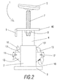
- the stabiliser device (1) essentially comprises an elongated body (2) with a substantially rectangular and internally hollow base which is made of steel, and which is also attached to a lower base (3) platform.
- This elongated body (2) includes a cylinder (not shown) on the inside which is coupled to an axially extendible piston (4) through the elongated body (2) which is attached to a support region intended to be in contact with a surface of the vehicle to be supported, which consists of an elongated plate (5).
- the upper end of the piston (4) is joined by threading to a flat end (40) in the form of a plate.
- the aforementioned base platform (3) has gripping means which are comprised of two handles (6) positioned facing each other.
- height adjustment means are provided for adjusting the height between the elongated plate (5) and the movable piston (4).
- elongated rod (7) extending perpendicular to the base (3) platform, being exteriorly threaded along its entire length which is superiorly connected to the elongated plate (5), wherein said rod (7) can be coupled to a nut (8) and which is positioned and fixedly soldered preferably below the flat end (40).
- the user can manually adjust the height of the elongated plate (5) by raising or lowering the rod (7), as seen in Figure 4 by the use of arrows.
- the stabiliser device (1) includes locking means for securing the position of the piston (4) relative to the cylinder, in the non-operational or deactivated position, as well as positioning means for positioning the piston relative to the elongated body (2), that actuate on extension or activation of the stabiliser device (1), which is detailed below.
- the locking means comprise a grip portion (9) formed by a profile in the form of a "U” that projects from one side of the flat end (40) which can be resiliently coupled to a rotary retainer (10) which rotates (as indicated by arrows in Figure 2 ) via a pin (11) which crosses through said rotary retainer (10) and is coupled to a support (12) that projects laterally from the elongated body (2).
- Securing the rotary retainer (10) on the grip portion (9) is carried out using a notch (13) that is present on the underside of said rotary retainer (10).
- the flat end (40) includes handles (41) that project laterally and make the pick-up operation easier for the stabiliser device (1) by means of a connecting manoeuver performed between the handles (41) and the handles (6) described above, thereby enabling the actuation of the locking means that prevent the piston from inadvertently extending.
- This locking mechanism maintains the retained or pick-up position of the device for storage and transport, once the device is placed on the stabilisation point of the vehicle, the rotary retainer (10) is disengaged from the gripping portion (9) and permits activation of the stabiliser device by extension thereof caused by the cylinder and the piston (4).
- the positioning means comprise an elongated toothed region (14) connected to the cylinder such that it extends longitudinally relative to said cylinder and a grip (15) that can be coupled to said toothed region (14), said grip (15) being associated with the elongated body (2) by an extension formed by a support (16) that projects outwardly on which rotary pivot (17) is arranged which passes through the grip (15), as shown more clearly in Figure 3 .
- the positioning means further have an elastic spring (18) to return the grip (15) to its initial position once it has been operated manually.
- the grip (15) can also be moved linearly on the rotary pivot (17) such that when picking up or closing the stabiliser device (1) the grip (15) can be positioned such that it is not interacting with the toothed region (14).
- the rotary pivot (17) may consist of a rod with a threaded portion coupled to a nut.
- the grip (15) makes contact with the toothed elongated region (14) by means of an inclined projection (151) protruding from the upper end of said grip (15).
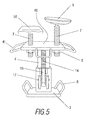
- the stabiliser device (1) is similar to that shown in Figures 1 and 2 , therefore the same elements have the same reference numbers, the main difference being the fact that it has two support regions (5, 50) each provided with height adjustment means identical to those described above, therefore it is not necessary to go into greater detail in the description thereof, one of said support regions (50) formed by an elongated plate having a non-planar upper surface.
- Figures 6 and 7 show an accessory that is suitable, for example, when there is no space for inserting part of the stabiliser device (1) under the collided car due, for example, to the wheels of the vehicle being deflated.
- This accessory (19) that can be removably mounted on the piston (4) is formed by a body that has an additional contact zone (191) to come into contact with part of the vehicle body to be handled and an attachment zone (192) that can be adapted to the dimensions of the top of the piston (4) having a substantially flat elongated shape, that has a hook extension (193) at one end.
- FIGs 8 and 9 show a pusher element (20) intended to enable the handling of a vehicle, for example, when arranged in a position as shown in Figure 1 .
- this pusher element (20) that actuates as a wedge has an elongated body formed by two elongated longitudinal members on which a plurality of crossmembers are arranged, the lower end of the pusher element (20) being rotably coupled to a support base (21) made of metal material, while an area near the upper end of the pusher element (20) is coupled to the piston (4), wherein the stabiliser device (1) may be arranged on said support base (21).
- connecting the pusher element (20) with the piston (4) is performed by means of a plate (25) that is rotably coupled on the two longitudinal members of the pusher element (20), wherein the plate (25) is placed on a flat end (40) and is subsequently clamped by screws (26) passing through a corresponding nut (8), thereby ensuring that the plate (25) moves fixedly with the piston (4) during the upward and downward movement.
- the rotary connection of the pusher element (20) on the support base (21) is carried out by using a fixed axis (23) and arranged on the support base (21), wherein said axis (23) is located in a corresponding housing in the pusher element (20).
- the support base (21) has a positioning means for fixedly positioning the stabiliser device (1) on said support base (21), such positioning means consisting of a pair of parallel guides (22) separated from each other, on which the stabiliser device (1) described above can be placed slidably, as shown in Figure 9 , although the use of any other suitable positioning means will be apparent to one skilled in the art.
- positioning means consisting of a pair of parallel guides (22) separated from each other, on which the stabiliser device (1) described above can be placed slidably, as shown in Figure 9 , although the use of any other suitable positioning means will be apparent to one skilled in the art.
- such pair of guides (22) can be provided with a displacement mechanism for changing the relative position of the pair of guides (22) relative to the distance from the axis (23), thereby enabling the angle of inclination to be modified.
- the support base (21) may also include anchoring means in order to firmly secure the support base (21) on the ground, which consists of a plurality of pointed elements (24) protruding from the bottom of the support base (21) in a downward direction.
Landscapes
- Engineering & Computer Science (AREA)
- Health & Medical Sciences (AREA)
- General Health & Medical Sciences (AREA)
- Business, Economics & Management (AREA)
- Emergency Management (AREA)
- General Engineering & Computer Science (AREA)
- Mechanical Engineering (AREA)
- Fluid-Damping Devices (AREA)
- Handcart (AREA)
- Vehicle Cleaning, Maintenance, Repair, Refitting, And Outriggers (AREA)
Applications Claiming Priority (1)
| Application Number | Priority Date | Filing Date | Title |
|---|---|---|---|
| ES201330489A ES2504840R1 (es) | 2013-04-05 | 2013-04-05 | Sistema de estabilización para soportar un vehículo o similar en operaciones de rescate ante accidentes |
Publications (3)
| Publication Number | Publication Date |
|---|---|
| EP2786784A2 true EP2786784A2 (de) | 2014-10-08 |
| EP2786784A3 EP2786784A3 (de) | 2015-12-02 |
| EP2786784B1 EP2786784B1 (de) | 2021-11-10 |
Family
ID=50112627
Family Applications (1)
| Application Number | Title | Priority Date | Filing Date |
|---|---|---|---|
| EP14382132.0A Active EP2786784B1 (de) | 2013-04-05 | 2014-04-04 | Stabilisierungssystem zum Stützen eines Fahrzeugs oder dergleichen bei Unfallrettungsoperationen |
Country Status (2)
| Country | Link |
|---|---|
| EP (1) | EP2786784B1 (de) |
| ES (2) | ES2504840R1 (de) |
Cited By (2)
| Publication number | Priority date | Publication date | Assignee | Title |
|---|---|---|---|---|
| CN109179281A (zh) * | 2018-10-27 | 2019-01-11 | 杨何应 | 一种立式千斤顶顶部延展支撑设备 |
| CN113510497A (zh) * | 2021-03-26 | 2021-10-19 | 中车长春轨道客车股份有限公司 | 轨道车辆铝合金车体型材底部随形支撑装置 |
Family Cites Families (14)
| Publication number | Priority date | Publication date | Assignee | Title |
|---|---|---|---|---|
| US1860014A (en) * | 1927-10-06 | 1932-05-24 | Cheape John Albert | Lifting jack |
| US1872959A (en) * | 1929-03-27 | 1932-08-23 | Charles H Johnson | Automobile jack |
| DE2659710A1 (de) * | 1976-12-31 | 1978-07-06 | Wilhelm Hoch | Hebegeraet |
| JPS5989774U (ja) * | 1982-12-09 | 1984-06-18 | トヨタ自動車株式会社 | フ−ドサポ−ト装置 |
| US4641813A (en) * | 1985-03-13 | 1987-02-10 | Safe-T-Jack | Dual automobile jack for consumer use |
| EP0720964A1 (de) * | 1995-01-04 | 1996-07-10 | Jin Soo Park | Hilfsvorrichtung eines hydraulischen Hebeblocks |
| DE29605222U1 (de) * | 1996-03-22 | 1996-06-13 | Glück, Rainer, 90766 Fürth | Haltevorrichtung |
| US6145813A (en) * | 1998-09-25 | 2000-11-14 | Anderson; Marcus W. | Manual vehicle jack assembly |
| CA2281260C (en) * | 1999-08-31 | 2005-05-24 | Wheeltronic Ltd. | Inground lift |
| US6691983B2 (en) * | 2002-05-23 | 2004-02-17 | Harry H. Arzouman | Economical lifting device-jack stand |
| US20070170405A1 (en) * | 2005-02-25 | 2007-07-26 | Robert Gallart | Tool devices |
| US7434782B2 (en) * | 2006-10-31 | 2008-10-14 | Arzouman Harry H | Commercial lifting device-controls for power unit |
| WO2009051523A1 (en) * | 2007-10-15 | 2009-04-23 | Husqvarna Aktiebolag | Operating system and telescopic tube |
| US8608130B2 (en) * | 2010-04-20 | 2013-12-17 | Shinn Fu Corporation | Lifting apparatus |
-
2013
- 2013-04-05 ES ES201330489A patent/ES2504840R1/es active Pending
-
2014
- 2014-04-04 ES ES14382132T patent/ES2905184T3/es active Active
- 2014-04-04 EP EP14382132.0A patent/EP2786784B1/de active Active
Non-Patent Citations (1)
| Title |
|---|
| None |
Cited By (2)
| Publication number | Priority date | Publication date | Assignee | Title |
|---|---|---|---|---|
| CN109179281A (zh) * | 2018-10-27 | 2019-01-11 | 杨何应 | 一种立式千斤顶顶部延展支撑设备 |
| CN113510497A (zh) * | 2021-03-26 | 2021-10-19 | 中车长春轨道客车股份有限公司 | 轨道车辆铝合金车体型材底部随形支撑装置 |
Also Published As
| Publication number | Publication date |
|---|---|
| ES2504840R1 (es) | 2014-10-31 |
| EP2786784A3 (de) | 2015-12-02 |
| ES2905184T3 (es) | 2022-04-07 |
| ES2504840A2 (es) | 2014-10-08 |
| EP2786784B1 (de) | 2021-11-10 |
Similar Documents
| Publication | Publication Date | Title |
|---|---|---|
| US10035688B1 (en) | Tire handling cart | |
| EP2285717B1 (de) | Fahrzeugsicherung eines tragrahmens | |
| US7992681B2 (en) | Portable safety ladder assembly | |
| US20090108147A1 (en) | Trailer support safety stand | |
| US5261150A (en) | Automated hazardous waste accessing apparatus | |
| CA2600811C (en) | Cribbing apparatus | |
| US20130264442A1 (en) | Mobile roof safety device | |
| US20150284040A1 (en) | Adjustable spare tire cart | |
| EP2786784B1 (de) | Stabilisierungssystem zum Stützen eines Fahrzeugs oder dergleichen bei Unfallrettungsoperationen | |
| US4099634A (en) | Combined motor puller and stand | |
| US20050045683A1 (en) | Vehicle exterior material clamping apparatus with scissors-like closure motion | |
| CA2967898C (en) | Straightening apparatus | |
| US11452892B2 (en) | Mobile fall restraint apparatus | |
| JP5940889B2 (ja) | 落下防止装置 | |
| WO2012063841A1 (ja) | 二輪車の輸送用固定装置 | |
| AU2018360616B2 (en) | A device for strapping a load at heights | |
| CZ20002535A3 (cs) | Zařízení pro uložení a přepravu motocyklu | |
| EP3160832A1 (de) | Automatische hubstütze für ein wohnmobil | |
| JP2014177198A (ja) | 自転車保管器具構造 | |
| GB2440676A (en) | Restraint for fork-lift truck | |
| KR102575335B1 (ko) | 코일 이동 방지 장치 | |
| US20110057415A1 (en) | Tow Truck Wheel Restraint and Methods of Using Same | |
| KR101634000B1 (ko) | 소재 운반 대차 | |
| JP6470519B2 (ja) | キャリーカー | |
| US9340067B2 (en) | Tire handling tool |
Legal Events
| Date | Code | Title | Description |
|---|---|---|---|
| PUAI | Public reference made under article 153(3) epc to a published international application that has entered the european phase |
Free format text: ORIGINAL CODE: 0009012 |
|
| 17P | Request for examination filed |
Effective date: 20140404 |
|
| AK | Designated contracting states |
Kind code of ref document: A2 Designated state(s): AL AT BE BG CH CY CZ DE DK EE ES FI FR GB GR HR HU IE IS IT LI LT LU LV MC MK MT NL NO PL PT RO RS SE SI SK SM TR |
|
| AX | Request for extension of the european patent |
Extension state: BA ME |
|
| PUAL | Search report despatched |
Free format text: ORIGINAL CODE: 0009013 |
|
| AK | Designated contracting states |
Kind code of ref document: A3 Designated state(s): AL AT BE BG CH CY CZ DE DK EE ES FI FR GB GR HR HU IE IS IT LI LT LU LV MC MK MT NL NO PL PT RO RS SE SI SK SM TR |
|
| AX | Request for extension of the european patent |
Extension state: BA ME |
|
| RIC1 | Information provided on ipc code assigned before grant |
Ipc: A62B 99/00 20090101ALI20151028BHEP Ipc: B66F 3/00 20060101ALI20151028BHEP Ipc: B60S 9/04 20060101ALI20151028BHEP Ipc: A62B 3/00 20060101AFI20151028BHEP |
|
| R17P | Request for examination filed (corrected) |
Effective date: 20160419 |
|
| GRAP | Despatch of communication of intention to grant a patent |
Free format text: ORIGINAL CODE: EPIDOSNIGR1 |
|
| STAA | Information on the status of an ep patent application or granted ep patent |
Free format text: STATUS: GRANT OF PATENT IS INTENDED |
|
| INTG | Intention to grant announced |
Effective date: 20210611 |
|
| GRAS | Grant fee paid |
Free format text: ORIGINAL CODE: EPIDOSNIGR3 |
|
| GRAA | (expected) grant |
Free format text: ORIGINAL CODE: 0009210 |
|
| STAA | Information on the status of an ep patent application or granted ep patent |
Free format text: STATUS: THE PATENT HAS BEEN GRANTED |
|
| AK | Designated contracting states |
Kind code of ref document: B1 Designated state(s): AL AT BE BG CH CY CZ DE DK EE ES FI FR GB GR HR HU IE IS IT LI LT LU LV MC MK MT NL NO PL PT RO RS SE SI SK SM TR |
|
| REG | Reference to a national code |
Ref country code: GB Ref legal event code: FG4D |
|
| REG | Reference to a national code |
Ref country code: AT Ref legal event code: REF Ref document number: 1445524 Country of ref document: AT Kind code of ref document: T Effective date: 20211115 Ref country code: CH Ref legal event code: EP |
|
| REG | Reference to a national code |
Ref country code: DE Ref legal event code: R096 Ref document number: 602014081141 Country of ref document: DE |
|
| REG | Reference to a national code |
Ref country code: IE Ref legal event code: FG4D |
|
| REG | Reference to a national code |
Ref country code: LT Ref legal event code: MG9D |
|
| REG | Reference to a national code |
Ref country code: NL Ref legal event code: MP Effective date: 20211110 |
|
| REG | Reference to a national code |
Ref country code: ES Ref legal event code: FG2A Ref document number: 2905184 Country of ref document: ES Kind code of ref document: T3 Effective date: 20220407 |
|
| REG | Reference to a national code |
Ref country code: AT Ref legal event code: MK05 Ref document number: 1445524 Country of ref document: AT Kind code of ref document: T Effective date: 20211110 |
|
| PG25 | Lapsed in a contracting state [announced via postgrant information from national office to epo] |
Ref country code: RS Free format text: LAPSE BECAUSE OF FAILURE TO SUBMIT A TRANSLATION OF THE DESCRIPTION OR TO PAY THE FEE WITHIN THE PRESCRIBED TIME-LIMIT Effective date: 20211110 Ref country code: LT Free format text: LAPSE BECAUSE OF FAILURE TO SUBMIT A TRANSLATION OF THE DESCRIPTION OR TO PAY THE FEE WITHIN THE PRESCRIBED TIME-LIMIT Effective date: 20211110 Ref country code: FI Free format text: LAPSE BECAUSE OF FAILURE TO SUBMIT A TRANSLATION OF THE DESCRIPTION OR TO PAY THE FEE WITHIN THE PRESCRIBED TIME-LIMIT Effective date: 20211110 Ref country code: BG Free format text: LAPSE BECAUSE OF FAILURE TO SUBMIT A TRANSLATION OF THE DESCRIPTION OR TO PAY THE FEE WITHIN THE PRESCRIBED TIME-LIMIT Effective date: 20220210 Ref country code: AT Free format text: LAPSE BECAUSE OF FAILURE TO SUBMIT A TRANSLATION OF THE DESCRIPTION OR TO PAY THE FEE WITHIN THE PRESCRIBED TIME-LIMIT Effective date: 20211110 |
|
| PG25 | Lapsed in a contracting state [announced via postgrant information from national office to epo] |
Ref country code: IS Free format text: LAPSE BECAUSE OF FAILURE TO SUBMIT A TRANSLATION OF THE DESCRIPTION OR TO PAY THE FEE WITHIN THE PRESCRIBED TIME-LIMIT Effective date: 20220310 Ref country code: SE Free format text: LAPSE BECAUSE OF FAILURE TO SUBMIT A TRANSLATION OF THE DESCRIPTION OR TO PAY THE FEE WITHIN THE PRESCRIBED TIME-LIMIT Effective date: 20211110 Ref country code: PT Free format text: LAPSE BECAUSE OF FAILURE TO SUBMIT A TRANSLATION OF THE DESCRIPTION OR TO PAY THE FEE WITHIN THE PRESCRIBED TIME-LIMIT Effective date: 20220310 Ref country code: PL Free format text: LAPSE BECAUSE OF FAILURE TO SUBMIT A TRANSLATION OF THE DESCRIPTION OR TO PAY THE FEE WITHIN THE PRESCRIBED TIME-LIMIT Effective date: 20211110 Ref country code: NO Free format text: LAPSE BECAUSE OF FAILURE TO SUBMIT A TRANSLATION OF THE DESCRIPTION OR TO PAY THE FEE WITHIN THE PRESCRIBED TIME-LIMIT Effective date: 20220210 Ref country code: NL Free format text: LAPSE BECAUSE OF FAILURE TO SUBMIT A TRANSLATION OF THE DESCRIPTION OR TO PAY THE FEE WITHIN THE PRESCRIBED TIME-LIMIT Effective date: 20211110 Ref country code: LV Free format text: LAPSE BECAUSE OF FAILURE TO SUBMIT A TRANSLATION OF THE DESCRIPTION OR TO PAY THE FEE WITHIN THE PRESCRIBED TIME-LIMIT Effective date: 20211110 Ref country code: HR Free format text: LAPSE BECAUSE OF FAILURE TO SUBMIT A TRANSLATION OF THE DESCRIPTION OR TO PAY THE FEE WITHIN THE PRESCRIBED TIME-LIMIT Effective date: 20211110 Ref country code: GR Free format text: LAPSE BECAUSE OF FAILURE TO SUBMIT A TRANSLATION OF THE DESCRIPTION OR TO PAY THE FEE WITHIN THE PRESCRIBED TIME-LIMIT Effective date: 20220211 |
|
| PG25 | Lapsed in a contracting state [announced via postgrant information from national office to epo] |
Ref country code: SM Free format text: LAPSE BECAUSE OF FAILURE TO SUBMIT A TRANSLATION OF THE DESCRIPTION OR TO PAY THE FEE WITHIN THE PRESCRIBED TIME-LIMIT Effective date: 20211110 Ref country code: SK Free format text: LAPSE BECAUSE OF FAILURE TO SUBMIT A TRANSLATION OF THE DESCRIPTION OR TO PAY THE FEE WITHIN THE PRESCRIBED TIME-LIMIT Effective date: 20211110 Ref country code: RO Free format text: LAPSE BECAUSE OF FAILURE TO SUBMIT A TRANSLATION OF THE DESCRIPTION OR TO PAY THE FEE WITHIN THE PRESCRIBED TIME-LIMIT Effective date: 20211110 Ref country code: EE Free format text: LAPSE BECAUSE OF FAILURE TO SUBMIT A TRANSLATION OF THE DESCRIPTION OR TO PAY THE FEE WITHIN THE PRESCRIBED TIME-LIMIT Effective date: 20211110 Ref country code: DK Free format text: LAPSE BECAUSE OF FAILURE TO SUBMIT A TRANSLATION OF THE DESCRIPTION OR TO PAY THE FEE WITHIN THE PRESCRIBED TIME-LIMIT Effective date: 20211110 Ref country code: CZ Free format text: LAPSE BECAUSE OF FAILURE TO SUBMIT A TRANSLATION OF THE DESCRIPTION OR TO PAY THE FEE WITHIN THE PRESCRIBED TIME-LIMIT Effective date: 20211110 |
|
| REG | Reference to a national code |
Ref country code: DE Ref legal event code: R097 Ref document number: 602014081141 Country of ref document: DE |
|
| PLBE | No opposition filed within time limit |
Free format text: ORIGINAL CODE: 0009261 |
|
| STAA | Information on the status of an ep patent application or granted ep patent |
Free format text: STATUS: NO OPPOSITION FILED WITHIN TIME LIMIT |
|
| 26N | No opposition filed |
Effective date: 20220811 |
|
| PG25 | Lapsed in a contracting state [announced via postgrant information from national office to epo] |
Ref country code: AL Free format text: LAPSE BECAUSE OF FAILURE TO SUBMIT A TRANSLATION OF THE DESCRIPTION OR TO PAY THE FEE WITHIN THE PRESCRIBED TIME-LIMIT Effective date: 20211110 |
|
| PG25 | Lapsed in a contracting state [announced via postgrant information from national office to epo] |
Ref country code: SI Free format text: LAPSE BECAUSE OF FAILURE TO SUBMIT A TRANSLATION OF THE DESCRIPTION OR TO PAY THE FEE WITHIN THE PRESCRIBED TIME-LIMIT Effective date: 20211110 |
|
| REG | Reference to a national code |
Ref country code: CH Ref legal event code: PL |
|
| GBPC | Gb: european patent ceased through non-payment of renewal fee |
Effective date: 20220404 |
|
| REG | Reference to a national code |
Ref country code: BE Ref legal event code: MM Effective date: 20220430 |
|
| PG25 | Lapsed in a contracting state [announced via postgrant information from national office to epo] |
Ref country code: MC Free format text: LAPSE BECAUSE OF FAILURE TO SUBMIT A TRANSLATION OF THE DESCRIPTION OR TO PAY THE FEE WITHIN THE PRESCRIBED TIME-LIMIT Effective date: 20211110 Ref country code: LU Free format text: LAPSE BECAUSE OF NON-PAYMENT OF DUE FEES Effective date: 20220404 Ref country code: LI Free format text: LAPSE BECAUSE OF NON-PAYMENT OF DUE FEES Effective date: 20220430 Ref country code: GB Free format text: LAPSE BECAUSE OF NON-PAYMENT OF DUE FEES Effective date: 20220404 Ref country code: CH Free format text: LAPSE BECAUSE OF NON-PAYMENT OF DUE FEES Effective date: 20220430 |
|
| PG25 | Lapsed in a contracting state [announced via postgrant information from national office to epo] |
Ref country code: BE Free format text: LAPSE BECAUSE OF NON-PAYMENT OF DUE FEES Effective date: 20220430 |
|
| PG25 | Lapsed in a contracting state [announced via postgrant information from national office to epo] |
Ref country code: IE Free format text: LAPSE BECAUSE OF NON-PAYMENT OF DUE FEES Effective date: 20220404 |
|
| PG25 | Lapsed in a contracting state [announced via postgrant information from national office to epo] |
Ref country code: IT Free format text: LAPSE BECAUSE OF FAILURE TO SUBMIT A TRANSLATION OF THE DESCRIPTION OR TO PAY THE FEE WITHIN THE PRESCRIBED TIME-LIMIT Effective date: 20211110 |
|
| P01 | Opt-out of the competence of the unified patent court (upc) registered |
Effective date: 20230518 |
|
| PG25 | Lapsed in a contracting state [announced via postgrant information from national office to epo] |
Ref country code: HU Free format text: LAPSE BECAUSE OF FAILURE TO SUBMIT A TRANSLATION OF THE DESCRIPTION OR TO PAY THE FEE WITHIN THE PRESCRIBED TIME-LIMIT; INVALID AB INITIO Effective date: 20140404 |
|
| PG25 | Lapsed in a contracting state [announced via postgrant information from national office to epo] |
Ref country code: MK Free format text: LAPSE BECAUSE OF FAILURE TO SUBMIT A TRANSLATION OF THE DESCRIPTION OR TO PAY THE FEE WITHIN THE PRESCRIBED TIME-LIMIT Effective date: 20211110 Ref country code: CY Free format text: LAPSE BECAUSE OF FAILURE TO SUBMIT A TRANSLATION OF THE DESCRIPTION OR TO PAY THE FEE WITHIN THE PRESCRIBED TIME-LIMIT Effective date: 20211110 |
|
| PGFP | Annual fee paid to national office [announced via postgrant information from national office to epo] |
Ref country code: FR Payment date: 20240430 Year of fee payment: 11 |
|
| PG25 | Lapsed in a contracting state [announced via postgrant information from national office to epo] |
Ref country code: MT Free format text: LAPSE BECAUSE OF FAILURE TO SUBMIT A TRANSLATION OF THE DESCRIPTION OR TO PAY THE FEE WITHIN THE PRESCRIBED TIME-LIMIT Effective date: 20211110 |
|
| PGFP | Annual fee paid to national office [announced via postgrant information from national office to epo] |
Ref country code: DE Payment date: 20250428 Year of fee payment: 12 |
|
| PGFP | Annual fee paid to national office [announced via postgrant information from national office to epo] |
Ref country code: ES Payment date: 20250513 Year of fee payment: 12 |
|
| PG25 | Lapsed in a contracting state [announced via postgrant information from national office to epo] |
Ref country code: TR Free format text: LAPSE BECAUSE OF FAILURE TO SUBMIT A TRANSLATION OF THE DESCRIPTION OR TO PAY THE FEE WITHIN THE PRESCRIBED TIME-LIMIT Effective date: 20211110 |
|
| PG25 | Lapsed in a contracting state [announced via postgrant information from national office to epo] |
Ref country code: FR Free format text: LAPSE BECAUSE OF NON-PAYMENT OF DUE FEES Effective date: 20250430 |