EP2786558B1 - Image processing system, vehicle including the same, image processing method, and computer program product - Google Patents
Image processing system, vehicle including the same, image processing method, and computer program product Download PDFInfo
- Publication number
- EP2786558B1 EP2786558B1 EP12854204.0A EP12854204A EP2786558B1 EP 2786558 B1 EP2786558 B1 EP 2786558B1 EP 12854204 A EP12854204 A EP 12854204A EP 2786558 B1 EP2786558 B1 EP 2786558B1
- Authority
- EP
- European Patent Office
- Prior art keywords
- image
- area
- light
- imaging
- image processing
- Prior art date
- Legal status (The legal status is an assumption and is not a legal conclusion. Google has not performed a legal analysis and makes no representation as to the accuracy of the status listed.)
- Not-in-force
Links
Images


Classifications
-
- H—ELECTRICITY
- H04—ELECTRIC COMMUNICATION TECHNIQUE
- H04N—PICTORIAL COMMUNICATION, e.g. TELEVISION
- H04N7/00—Television systems
- H04N7/18—Closed-circuit television [CCTV] systems, i.e. systems in which the video signal is not broadcast
- H04N7/183—Closed-circuit television [CCTV] systems, i.e. systems in which the video signal is not broadcast for receiving images from a single remote source
-
- B—PERFORMING OPERATIONS; TRANSPORTING
- B60—VEHICLES IN GENERAL
- B60S—SERVICING, CLEANING, REPAIRING, SUPPORTING, LIFTING, OR MANOEUVRING OF VEHICLES, NOT OTHERWISE PROVIDED FOR
- B60S1/00—Cleaning of vehicles
- B60S1/02—Cleaning windscreens, windows or optical devices
- B60S1/04—Wipers or the like, e.g. scrapers
- B60S1/06—Wipers or the like, e.g. scrapers characterised by the drive
- B60S1/08—Wipers or the like, e.g. scrapers characterised by the drive electrically driven
- B60S1/0818—Wipers or the like, e.g. scrapers characterised by the drive electrically driven including control systems responsive to external conditions, e.g. by detection of moisture, dirt or the like
- B60S1/0822—Wipers or the like, e.g. scrapers characterised by the drive electrically driven including control systems responsive to external conditions, e.g. by detection of moisture, dirt or the like characterized by the arrangement or type of detection means
- B60S1/0833—Optical rain sensor
- B60S1/0844—Optical rain sensor including a camera
-
- G—PHYSICS
- G06—COMPUTING OR CALCULATING; COUNTING
- G06V—IMAGE OR VIDEO RECOGNITION OR UNDERSTANDING
- G06V20/00—Scenes; Scene-specific elements
- G06V20/50—Context or environment of the image
- G06V20/56—Context or environment of the image exterior to a vehicle by using sensors mounted on the vehicle
-
- H—ELECTRICITY
- H04—ELECTRIC COMMUNICATION TECHNIQUE
- H04N—PICTORIAL COMMUNICATION, e.g. TELEVISION
- H04N23/00—Cameras or camera modules comprising electronic image sensors; Control thereof
- H04N23/50—Constructional details
- H04N23/55—Optical parts specially adapted for electronic image sensors; Mounting thereof
-
- H—ELECTRICITY
- H04—ELECTRIC COMMUNICATION TECHNIQUE
- H04N—PICTORIAL COMMUNICATION, e.g. TELEVISION
- H04N23/00—Cameras or camera modules comprising electronic image sensors; Control thereof
- H04N23/60—Control of cameras or camera modules
-
- H—ELECTRICITY
- H04—ELECTRIC COMMUNICATION TECHNIQUE
- H04N—PICTORIAL COMMUNICATION, e.g. TELEVISION
- H04N23/00—Cameras or camera modules comprising electronic image sensors; Control thereof
- H04N23/70—Circuitry for compensating brightness variation in the scene
- H04N23/75—Circuitry for compensating brightness variation in the scene by influencing optical camera components
-
- H—ELECTRICITY
- H04—ELECTRIC COMMUNICATION TECHNIQUE
- H04N—PICTORIAL COMMUNICATION, e.g. TELEVISION
- H04N23/00—Cameras or camera modules comprising electronic image sensors; Control thereof
- H04N23/80—Camera processing pipelines; Components thereof
- H04N23/81—Camera processing pipelines; Components thereof for suppressing or minimising disturbance in the image signal generation
- H04N23/811—Camera processing pipelines; Components thereof for suppressing or minimising disturbance in the image signal generation by dust removal, e.g. from surfaces of the image sensor or processing of the image signal output by the electronic image sensor
Definitions
- the present invention relates to an image processing system for optically detecting a foreign matter attached to a surface of a windshield of a vehicle, and relates to a vehicle including the image processing system, an image processing method, and a computer program product.
- an image processing system that functions both as a sensing camera for acquiring information on around the vehicle and as a raindrop detection camera for detecting a raindrop attached to a windshield of the vehicle (for example, see Patent Literature 1: Japanese Patent No. 4326999 ).
- Such an image processing system is used in, for example, a system for automatically removing raindrops attached to a windshield of a vehicle by a windshield wiper.
- Patent Literature 1 discloses an image processing system that includes an image processing apparatus, a light source, and an optical filter so as to function both as a sensing camera and a raindrop detection camera, and that captures images of raindrops on the outer surface of the windshield by applying light from the light source.
- a bandpass filter for detecting a raindrop is provided in a part of the optical filter.
- the amount of light incident on the camera from the outside of the vehicle greatly varies between, for example, day and night or depending on weather.
- the variation is extremely large, ranging from 0.1 lux to a hundred thousand lux.
- it is necessary to increase the light emission intensity of the light source in proportion to the external light. Therefore, there are problems in terms of power consumption and in terms of safety affected by intensive light emitted to the outside of the vehicle.
- EP 1 507 138A discloses an image processing system that includes: a light source that emits light from one surface side of a transparent member to the transparent member; an imaging unit including an imaging element that captures light emitted by the light source and reflected from a foreign matter attached to the other surface of the transparent member and that captures light transmitted through the transparent member from the other surface side; and an image analyzing unit that analyzes captured image data captured by the imaging unit.
- the captured image data is formed of a first image area frame containing a first image area that is used for detecting a foreign matter and that corresponds to a predetermined area, and is formed of a second image area frame containing a second image area that corresponds to an effective imaging area excluding the predetermined area.
- JP 2009 004947A discloses an image sensor of a vehicle-mounted camera device, in which scan lines are read out for different image regions at different rates.
- the present invention has been made to solve the above problems in the conventional technologies, and it is an object of the present invention to provide an image processing system that can, in a system in which one imaging device detects both a foreign matter and information on around the vehicle, reduce the power consumption, enhance the safety, and prevent a reduction in the frame rate for sensing due to insertion of frames for detecting a foreign matter, and to provide a vehicle including the image processing system, an image processing method, and a computer program product.
- the invention is in the system of Claim 1, the method of Claim 10 and the program product of Claim 12.
- Fig. 1 is a schematic diagram illustrating an overall configuration of an in-vehicle device control system including an image processing system 110 according to the embodiment.
- the in-vehicle device control system controls light distribution of a headlight 104, controls driving of a windshield wiper 107 for removing a foreign matter attached to a windshield (transparent member) 105, and controls other in-vehicle devices, by using captured image data of a front area in a running direction of a vehicle 100, which is captured by an imaging unit 101 installed in the vehicle 100, such as a car.
- the in-vehicle device control system illustrated in Fig. 1 mainly includes the imaging unit 101, an image analyzing unit (image analyzing means) 102, a headlight control unit 103, a windshield wiper control unit 106, and a vehicle drive control unit 108.
- the image processing system 110 of the embodiment includes the imaging unit 101 and the image analyzing unit 102.
- the image analyzing unit 102 has a function to control the imaging unit 101 and a function to analyze captured image data transmitted from the imaging unit 101.
- the image analyzing unit 102 analyzes the captured image data transmitted from the imaging unit 101 to detect a foreign matter, such as a raindrop, attached to the windshield 105, to calculate positions, directions, or distances of other vehicles in front of the vehicle 100 in the captured image data, or to detect a detection object, such as a white line (compartment line), on the road within an imaging range.
- a detection object such as a white line (compartment line)
- information on the positions, the directions, and the distances of the other vehicles in front of the vehicle 100 and information on the white line (compartment line) on the road are also described as around-vehicle information.
- To detect other vehicles leading vehicles running in the same running direction as the vehicle 100 are detected by discriminating the taillights of the other vehicles, and oncoming vehicles running in the opposite direction of the vehicle 100 are detected by discriminating the headlights of the other vehicles.
- the calculation result obtained by the image analyzing unit 102 is sent to the headlight control unit 103.
- the headlight control unit 103 generates, for example, a control signal for controlling the headlight 104, which is an in-vehicle device of the vehicle 100, based on distance data calculated by the image analyzing unit 102.
- the headlight control unit 103 controls switching between high beam and low beam of the headlight or controls partial blocking of the headlight 104 in order to ensure the field of vision of the driver of the vehicle 100 while preventing intensive light from the headlight of the vehicle 100 from entering the eyes of the drivers of leading vehicles and oncoming vehicles to thereby prevent the drivers of the other vehicles from dazzling.
- the calculation result obtained by the image analyzing unit 102 is also sent to the windshield wiper control unit 106.
- the windshield wiper control unit 106 causes the windshield wiper 107 to remove an extraneous matter, such as a raindrop, attached to the windshield 105 of the vehicle 100.
- the windshield wiper control unit 106 receives a foreign matter detection result obtained by the image analyzing unit 102 and generates a control signal for controlling the windshield wiper 107.
- the control signal generated by the windshield wiper control unit 106 is sent to the windshield wiper 107, the windshield wiper 107 is driven to operate to ensure the field of vision of the driver of the vehicle 100.
- the calculation result obtained by the image analyzing unit 102 is also sent to the vehicle drive control unit 108.
- the vehicle drive control unit 108 issues an alarm to the driver of the vehicle 100 or supports driving by controlling a wheel or a brake of the vehicle when, for example, the vehicle 100 drifts from a lane separated by white lines, based on a white line detection result obtained by the image analyzing unit 102.
- Fig. 2 is a schematic diagram illustrating an overall configuration of the imaging unit 101 included in the image processing system 110 according to the embodiment.
- the imaging unit 101 includes a cover 210 fixed to the inside of the vehicle 100, an imaging device 201 (imaging means), and a light source 202 that emits light from an inner surface (one surface) 105a side of the windshield 105 of the vehicle 100 toward the windshield 105.
- the imaging device 201 and the light source 202 are housed inside the cover 210.
- Fig. 2 illustrates an example in which one light source 202 is housed in the cover 210.
- the number of the light sources is not limited to one and may be plural.
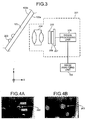
- Fig. 3 is a schematic diagram illustrating an overall configuration of the imaging device 201 included in the imaging unit 101.
- the imaging device 201 mainly includes an imaging lens 204 that condenses light emitted by the light source 202 (see Fig. 2 ) and reflected from a foreign matter 203 (hereinafter, an example is explained in which the foreign matter is a raindrop) attached to an outer surface (the other surface) 105b of the windshield 105, and condenses light transmitted through the windshield 105 from the outside of the vehicle 100 (from the outer surface 105b side); an imaging element 206 that captures the light condensed by the imaging lens 204; an optical filter 205 that is provided between the imaging lens 204 and the imaging element 206 and that transmits only light within a predetermined wavelength range in a predetermined area of the effective imaging area; a sensor board 207 on which the imaging element 206 is mounted; and a signal processing unit 208 that generates and outputs captured image data obtained by converting an analog electrical signal (the amount of light received by
- the imaging lens 204, the optical filter 205, the imaging element 206, and the sensor board 207 are provided in this order from the windshield 105 side.
- the signal processing unit 208 is electrically connected to the image analyzing unit 102.
- Fig. 3 illustrates an example in which the imaging element 206 and the signal processing unit 208 are separate from each other; however, the configuration of the imaging device 201 is not limited to this example.
- the imaging element 206 is provided with an analog-to-digital converting unit at each pixel, the analog-to-digital converting unit functions as the signal processing unit 208.
- the signal processing unit 208 is equipped in the imaging element 206.
- the imaging element 206 includes a not-illustrated register (sensor register).
- a rule for reading pixel data to be described below is controlled by changing a parameter value in the sensor register by the image analyzing unit 102.
- the light source 202 is provided so that an angle of view range of the imaging lens 204 and an irradiation area of the light source 202 overlap each other on the inner surface 105a of the windshield 105.
- a light source with a wavelength and a light intensity in the eye-safe band is used as the light source 202.
- the imaging lens 204 is formed of, for example, a plurality of lenses, and is focused on infinity or between infinity and the outer surface 105b of the windshield 105.
- the light source 202 is used to detect a raindrop attached to the outer surface 105b of the windshield 105.
- the raindrop 203 is attached to the outer surface 105b of the windshield 105, light emitted by the light source 202 is reflected from the interface between the raindrop 203 and air, and the reflected light enters the imaging device 201.
- the raindrop 203 is not attached to the outer surface 105b of the windshield 105, a part of light emitted by the light source 202 is output to the outside through the windshield 105, while the rest of the light is reflected from the inner surface 105a of the windshield 105 or from the interface between the outer surface 105b and air and the reflected light enters the imaging device 201.
- the light source 202 a light emitting diode (LED) or a semiconductor laser (LD) may be used.
- the emission wavelength of the light source 202 is preferably, for example, the wavelength in the visible light region or in the infrared region.
- a wavelength in the infrared region between 750 nm and 1000 nm.
- the light source 202 may be configured to perform continuous emission (CW emission) or perform pulse emission at a predetermined timing.
- CW emission continuous emission
- pulse emission pulse emission
- a configuration that performs pulse emission is preferable because it can reduce the influence of ambient light by synchronizing a timing of light emission and a timing of capturing an image.
- Light from an imaging range containing an object passes through the imaging lens 204, transmits the optical filter 205, and is converted into an electrical signal corresponding to the light intensity by the imaging element 206.
- the object may be a scenery in front of the vehicle 100 or a foreign matter such as a raindrop attached to the outer surface 105b of the windshield 105.
- the signal processing unit 208 When receiving the electrical signal (analog signal) output by the imaging element 206, the signal processing unit 208 outputs, as captured image data, a digital signal containing luminance (luminance information) of each of pixels on the imaging element 206 to a unit on the subsequent stage together with horizontal and vertical synchronous signals of an image, based on the electrical signal.
- the imaging lens 204 is focused on infinity or between infinity and the outer surface 105b of the windshield 105. Therefore, it becomes possible to acquire appropriate information from the captured image data obtained by the imaging device 201 not only for detecting the raindrop 203 attached to the windshield 105 but also for detecting a leading vehicle, an oncoming vehicle, or a white line.
- a shape recognition process is performed in which whether a raindrop candidate image in the captured image data is in a circular shape or not is determined to discriminate whether the raindrop candidate image is a raindrop image.
- a raindrop detection performance is increased when the imaging lens 204 is focused on infinity or between infinity and the windshield 105 as described above because the recognition rate of the shape (circular shape) of the raindrop can be increased due to occurrence of slight focus blur, compared with a case where the imaging lens 204 is focused on the raindrop 203 on the outer surface 105b of the windshield 105.
- Figs. 4A and B are diagrams for explaining infrared image data as captured image data for raindrop detection.
- Fig. 4A illustrates the infrared image data obtained when the imaging lens 204 is focused on the raindrop 203 on the outer surface 105b of the windshield 105
- Fig. 4B illustrates the infrared image data obtained when the imaging lens 204 is focused on infinity.
- a background image 203a appearing in the raindrop is also captured.
- the background image 203a as described above causes false detection of the raindrop 203.
- the luminance of a portion 203b of the raindrop increases in an arcuate shape as illustrated in Fig. 4A , and the shape of the portion with the increased luminance, that is, the shape of a raindrop image, changes depending on the direction of sunlight or the position of a street lamp.
- processing load increases and recognition accuracy is reduced.
- the imaging lens 204 is preferably focused on a point closer than infinity. Consequently, the taillight of the leading vehicle running far becomes out of focus and the number of light-receiving elements that receive light of the taillight can be increased. Therefore, it is possible to increase the recognition accuracy of the taillight, enabling to increase the detection accuracy of the leading vehicle.
- the imaging element 206 of the imaging device 201 receives not only the infrared-wavelength light from the light source 202 but also, for example, a large amount of ambient light, such as sunlight, including infrared-wavelength light. Therefore, to discriminate the infrared-wavelength light emitted by the light source 202 from the large amount of ambient light as described above, the light source 202 needs to emit a greater amount of light than the ambient light. However, it is often extremely difficult to use the light source 202 that can emit such a large amount of light.
- the imaging element 206 receives light from the light source 202 via a cut filter that cuts off light with a wavelength shorter than the emission wavelength of the light source 202 or via a bandpass filter whose peak transmittance is approximately the same as the emission wavelength of the light source 202. Consequently, it becomes possible to eliminate light with wavelengths other than the emission wavelength of the light source 202 when receiving light, so that the amount of light received by the imaging element 206 from the light source 202 becomes relatively greater than the ambient light. As a result, it becomes possible to discriminate the light emitted by the light source from the ambient light without using a light source that emits a large amount of light.
- the imaging element 206 cannot receive light in a wavelength band needed to detect a leading vehicle, an oncoming vehicle, or a white line, so that the detection may be negatively affected.
- an image area of the captured image data is divided into a raindrop detection image area (first image area) for detecting the raindrop 203 on the windshield 105 and an around-vehicle information detection image area (second image area) for detecting a leading vehicle, an oncoming vehicle, or a white line, and the wavelength band other than the infrared-wavelength light emitted by the light source 202 is eliminated only from a portion corresponding to the raindrop detection image area.
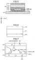
- Fig. 5 is a schematic cross-sectional view of the optical filter 205, the imaging element 206, and the sensor board 207 along a light transmission direction.
- the optical filter 205 includes, as illustrated in Fig. 5 , a substrate 220 that is transparent with respect to light in a bandwidth to be used (in the embodiment, a visible light region and an infrared region); a spectral filter layer (first spectral filter layer) 221 that is formed on the entire surface of the effective imaging area of the substrate 220 on the imaging lens 204 side and that transmits only light of a wavelength component in ranges from wavelengths ⁇ 1 to ⁇ 2 and wavelengths ⁇ 3 to ⁇ 4 ( ⁇ 1 ⁇ 2 ⁇ 3 ⁇ 4); a polarization filter layer 223 formed on the surface of the substrate 220 on the imaging element 206 side; a filler 224 provided on the polarization filter layer 223; and a spectral filter layer (second spectral filter layer) 222 that is formed in a part of the effective imaging area of the substrate 220 on the imaging element 206 side via the polarization filter layer 223 and the filler 224 and that transmits only light of a wavelength component in a range of
- the optical filter 205 has a structure in which the spectral filter layer 221 and the spectral filter layer 222 are overlaid with each other in the light transmission direction.
- Fig. 6 is a schematic front view for explaining how to divide an effective imaging area of the optical filter 205 having the spectral filter layer 221 and the spectral filter layer 222. As illustrated in Fig. 6 , the effective imaging area is divided into a visible light transmission area 211 corresponding to the around-vehicle information detection image area described above and infrared light transmission areas 212 corresponding to the raindrop detection image area described above.
- the visible light transmission area 211 be a half center area in the effective imaging area
- the infrared light transmission areas 212 be upper and lower areas in the effective imaging area.
- the infrared light transmission areas 212 may be provided in an upper, lower, or side part of the effective imaging area.
- Fig. 7 illustrates an example of the captured image data.
- An image of the headlight of an oncoming vehicle (not illustrated), an image of the taillight of a leading vehicle, and an image of a white line are likely to appear mainly in the center of a captured image, and an image of a road near and in front of the vehicle generally appears in the lower part of the captured image. Therefore, information needed to discriminate the headlight of the oncoming vehicle (not illustrated), the taillight of the leading vehicle, and the white line is concentrated in the center of the captured image, and information in the lower part of the captured image is less important for the discrimination. Meanwhile, the upper part of the captured image generally contains sky, and therefore, information in the upper part of the captured image is also less important.
- Fig. 7 it is preferable to set an around-vehicle information detection image area 213 in the center part of the captured image and set a raindrop detection image areas 214 in the upper and lower parts of the captured image. That is, as illustrated in Fig. 6 , it is preferable to set the infrared light transmission areas 212 for raindrop detection in the upper and lower parts of the effective imaging area, set the visible light transmission area 211 for around-vehicle information detection in the remaining center part of the effective imaging area, and divide the spectral filter layer 222 in accordance with the set areas.
- the imaging element 206 is an image sensor using a charge coupled device (CCD) or a complementary metal oxide semiconductor (CMOS), and includes photodiodes 206A as light-receiving elements.
- the photodiodes 206A are arranged in a two-dimensional array based on pixels.
- micro lenses 206B are provided on the incident side of the photodiodes 206A in accordance with the pixels of the photodiodes 206A, respectively.
- the imaging element 206 is bonded to a printed wiring board (PWB) by a wire bonding or the like to form the sensor board 207.
- PWB printed wiring board
- Fig. 8A and B illustrate graphs showing the spectral characteristics of the spectral filter layer 221 and the spectral filter layer 222.
- the light in the visible light region is used for detecting around-vehicle information and the light in the infrared region is used for detecting a raindrop.
- each of the photodiodes 206A included in the imaging element 206 of the embodiment is sensitive to the light in the infrared wavelength band. Therefore, when the imaging element 206 receives light including the infrared wavelength band, a captured image becomes entirely reddish. Consequently, in some cases, it becomes difficult to discriminate a red image portion corresponding to the taillight. Therefore, in the embodiment, the spectral filter layer 221 prevents infrared light with the wavelength range of 670nm to 940 nm from being transmitted (the transmittance of 5% or smaller is desirable). Consequently, the infrared wavelength band is eliminated from a captured image data part used for discriminating the taillight, so that the discrimination accuracy of the taillight can be improved.
- the spectral filter layer 221 may have the spectral characteristics illustrated in Fig. 9A instead of the spectral characteristics illustrated in Fig. 8A .
- the spectral filter layer 222 may have the spectral characteristics illustrated in Fig. 9B instead of the spectral characteristics illustrated in Fig. 8B (the characteristics including a bandpass filter with the peak transmittance of approximately the same as the emission wavelength of the light source 202). That is, the spectral characteristics of the spectral filter layer 222 may include the characteristics of cutting light on the shorter wavelength side than the emission wavelength of the light source 202.
- a hood of the vehicle may appear in the lower part of an imaging range.
- sunlight reflected from the hood of the vehicle, the taillight of a leading vehicle, or the like becomes ambient light
- the ambient light contained in the captured image data causes false discrimination of the headlight of an oncoming vehicle, the taillight of an incoming vehicle, and a white line.
- the spectral filter layer 221 for blocking light in the wavelength range of 670 nm to 940 nm is formed in the whole effective imaging area, the ambient light, such as the sunlight reflected from the hood or the taillight of the leading vehicle, can be eliminated. Therefore, the discrimination accuracy of the headlight of the oncoming vehicle, the taillight of the leading vehicle, and the white line can be improved.
- the spectral filter layer 221 and the spectral filter layer 222 are formed on both sides of the substrate 220 of the optical filter 205, it becomes possible to prevent warpage of the optical filter 205.
- the spectral filter layer is formed on only one side of the substrate 220, stress is applied to the substrate 220 resulting in warpage.
- the spectral filter layers are formed on both sides of the substrate 220, the effect of the stress can be cancelled out and the warpage can be prevented.
- the spectral filter layers 222 are provided in the upper and lower parts of the effective imaging area. If the infrared light transmission area 212 for raindrop detection is provided in only one of the upper and lower parts of the effective imaging area, it becomes difficult to bond the optical filter 205 and the imaging element 206 parallel to each other. If the optical filter 205 and the imaging element 206 are bonded at a tilt, the light path length varies between the upper part and the lower part of the effective imaging area. As a result, recognition accuracy may be reduced due to a false reading of around-vehicle information, such as a false reading of a coordinate of a white line when the white line is to be detected.
- the optical filter 205 and the imaging element 206 can be bonded parallel to each other. In this case, it becomes possible to ensure the greater infrared light transmission area 212, enabling to improve the detection accuracy of a raindrop.
- the polarization filter layer 223 is formed to cut ambient light that is reflected from the inner surface 105a of the windshield 105 after light is emitted from the light source 202.
- the majority of polarization components of such ambient light are an S-polarized component. That is, the polarizing axis of the polarization filter layer 223 is formed so as to block the light of a component (S-polarized component) in the polarization direction orthogonal to the normal line of the inner surface 105a of the windshield 105.
- the polarization filter layer 223 is designed so as to transmit only a polarization component (P-polarized component) parallel to a plane formed by two optical axes, that is an optical axis 22 of light emitted from the light source 202 toward the windshield 105 and an optical axis 23 of the imaging lens 204.
- the polarization filter layer 223 designed as above can also block additional light reflected from a dashboard or the like.
- the optical filter 205 is closely provided on the surface of the imaging element 206 on the micro lenses 206B side. It may be possible to provide a space between the optical filter 205 and the imaging element 206.
- the optical filter 205 is closely adhered to the imaging element 206, it becomes possible to easily match the boundary between the visible light transmission area 211 and the infrared light transmission areas 212 in the optical filter 205 with the boundary between the photodiodes 206A in the imaging element 206. Consequently, the boundary between the infrared light transmission areas 212 and the visible light transmission area 211 becomes distinct, so that the detection accuracy of a raindrop can be improved.
- the optical filter 205 and the imaging element 206 may be bonded by, for example, a UV adhesive.
- the optical filter 205 and the imaging element 206 may be bonded by UV bonding or thermocompression bonding at four side areas outside of the effective pixel range while they are supported by a spacer outside the effective pixel range used by imaging.
- the light sources when multiple light sources are used, it may be possible to cause the light sources to simultaneously emit light or to sequentially emit light.
- the light is emitted sequentially, and if the timing of light emission and the timing of imaging are synchronized with each other, the influence of the ambient light can be reduced.
- Fig. 7 illustrates an image obtained by simultaneously imaging the around-vehicle information and the raindrop.
- the around-vehicle information and the raindrop may be imaged separately.
- the imaging device 201 may capture an image at a first exposure amount (exposure time) for imaging a foreign matter, such as a raindrop, attached to the outer surface 105b of the windshield 105 in the infrared light transmission areas 212, and captures an image at a second exposure amount (exposure time) for imaging a distant view far from the position of the outer surface 105b of the windshield 105 in the visible light transmission area 211.
- the amount of light needed to capture an image differs between the visible light transmission area 211 and the infrared light transmission areas 212. However, in the above configuration in which two image are captured at different exposure time, it becomes possible to capture each image at the optimal exposure.
- the image analyzing unit 102 automatically adjusts exposure while detecting the amount of light that transmits the effective imaging area (the visible light transmission area 211) in which only the spectral filter layer 221 is formed.
- the image analyzing unit 102 automatically adjusts exposure while detecting the amount of light transmitting the effective imaging area (the infrared light transmission areas 212) in which the spectral filter layer 221 and the spectral filter layer 222 are formed.
- the amount of light greatly varies. Specifically, the irradiance near the vehicle varies between several tens of thousands lux during daytime and one lux or lower during nighttime. Therefore, it is necessary to adjust the exposure time depending on a scene to be imaged. To cope with this, it is satisfactory to perform known automatic exposure control.
- the imaging device 201 explained in the embodiment, because an object is near the road, it is desirable to control exposure based on an image of the road area.
- the effective imaging area in which the spectral filter layer 221 and the spectral filter layer 222 are formed because the area is designed so as to acquire only reflected light from a foreign matter, such as a raindrop, the amount of light does not greatly vary due to a peripheral environment. Therefore, it may be possible to capture an image at a fixed exposure time.
- the around-vehicle information detection image area is used by the image analyzing unit 102 to perform, for example, a process for discriminating a white line or a vehicle.
- the recognition process information between input image frames is also used. Therefore, it is necessary to input captured frames to the image analyzing unit 102 at predetermined time intervals or under a predetermined rule.
- a result of the raindrop detection is less likely to change in a short period of time compared with, for example, detection of a drift from a lane or detection of an inter-vehicular distance ahead, and the priority of the raindrop detection is lower in terms of safety. Therefore, it is desirable to insert a frame used for raindrop detection (hereinafter, described as a frame of a raindrop detection image area) into frames used for around-vehicle information detection (hereinafter, described as a frame of an around-vehicle information detection image area) at regular intervals.
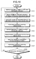
- Fig. 10 is a flowchart of the flow of an image processing method of the embodiment.
- the imaging device 201 repeats imaging sequentially n times at the second exposure amount for imaging the frame of the around-vehicle information detection image area (a second image area frame) (Step S120).
- the image analyzing unit 102 reads pixel data of the frame of the around-vehicle information detection image area imaged by the imaging device 201 (Step S121).
- the image analyzing unit 102 analyzes the frame of the around-vehicle information detection image area read at Step S121 (Step S122), and outputs an instruction signal for causing the headlight control unit 103, the vehicle drive control unit 108, or the like to perform various control operations (Step S123).
- the imaging device 201 repeats imaging sequentially m times at the first exposure amount for imaging the frame of the raindrop detection image area (a first image area frame) (Step S124).
- the image analyzing unit 102 reads pixel data of the frame of the raindrop detection image area imaged by the imaging device 201 (Step S125).
- the image analyzing unit 102 analyzes the frame of the raindrop detection image area read at Step S125 (Step S126), and outputs an instruction signal for causing the windshield wiper control unit 106 or the like to perform various control operations (Step S127).
- Step S128) a termination instruction issued by the driver of the vehicle 100, or the like.
- the number m of repetitions of imaging at the first exposure amount is smaller than the number n of repetitions of imaging at the second exposure amount. That is, the number of the frames for the raindrop detection image area is smaller than the number of the frames for the around-vehicle information detection image.
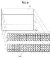
- a rule for reading the pixel data of the frame of the raindrop detection image area differs from a rule for reading the frame of the around-vehicle information detection image area. Specifically, a rule for reading pixel data from only the around-vehicle information detection image area is applied to the frame of the around-vehicle information detection image area, and a rule for reading pixel data from only the raindrop detection image area is applied to the frame of the raindrop detection image area.
- FIG. 11 is a diagram for explaining an example of pixel arrangement with regard to the photodiodes 206A arranged in the infrared light transmission areas 212 corresponding to the raindrop detection image area of the frame of the raindrop detection image area.
- each pixel of the photodiodes 206A is simplified; however, in actuality, the photodiodes 206A correspond to hundreds of thousands of pixels arranged two-dimensionally.
- Step S125 it is not desirable to read all pixel data corresponding to the raindrop detection image area, but desirable to read pixel data corresponding to the raindrop detection image area by thinning out pixels.
- Figs. 12A to D illustrate examples how pixels are thinned out.
- Fig. 12A it may be possible to skip reading a part or the whole of pixel data in a specific column.
- White squares in the drawing illustrate skipped pixels.
- Fig. 12D it may be possible to skip reading pixel data in a checker manner.
- the imaging element has the WXGA resolution (with 1280 x 800 pixel dots), and if pixels are thinned out to 640 x 640 dots for reading, it becomes possible to shorten the time needed to read by 1/4.
- the substrate 220 is made of a transparent material that can transmit light in a bandwidth to be used (in the embodiment, a visible light region and an infrared region), such as glass, sapphire, or crystal.
- a transparent material that can transmit light in a bandwidth to be used (in the embodiment, a visible light region and an infrared region), such as glass, sapphire, or crystal.
- glass in particular, quartz glass (refractive index of 1.46) or Tempax glass (refractive index of 1.51), which are cheap and durable, can preferably be used.
- the polarization filter layer 223 formed on the substrate 220 includes a polarizer formed with a wire grid structure as illustrated in Fig. 13 .
- the wire grid structure is a structure in which a metal wire (conductive wire) that is made with metal, such as aluminum, and that extends in a specific direction is arranged at a predetermined pitch.
- a wire pitch of the wire grid structure is sufficiently smaller (for example, 1/2 or smaller) than the wavelength band of emission light (for example, 400 nm to 800 nm), it becomes possible to reflect most of light of an electric field vector component that oscillates in the direction parallel to the longitudinal direction of the metal wire and it becomes possible to transmit most of light of an electric field vector component that oscillates in the direction orthogonal to the longitudinal direction of the metal wire. Therefore, the polarizer can be used as a polarizer that generates single polarization.
- the polarizer with the wire grid structure in general, when the cross-sectional area of the metal wire increases, the extinction ratio increases and the transmittance of the metal wile of a predetermined with or greater with respect to a cyclic width is reduced. If the cross section of the metal wire orthogonal to the longitudinal direction of the metal wire has a tapered shape, the transmittance and the wavelength dispersibility of polarization degree are low in a wide bandwidth, and the property of high extinction ratio is obtained.
- Fig. 14 is a diagram for explaining the longitudinal direction of the metal wire with the wire grid structure in the polarization filter layer 223 of the optical filter 205.
- the windshield 105 is generally curved, so that the polarization direction of light reflected from the dashboard changes at various positions in the effective imaging area. Therefore, it is desirable to provide the polarization filter layer 223 with a polarization axis that corresponds to a change in the polarization direction.
- the longitudinal direction (a direction of grooves) of the wire grid structure is changed at various positions in the polarization filter layer 223.
- the wire grid structure can be formed by a well-known semiconductor manufacturing process. Specifically, an aluminum thin film is deposited on the substrate 220, and thereafter, patterning is performed, and a sub wavelength concave-convex structure of the wire grid is formed by metal etching method or the like.
- the manufacturing process it is possible to adjust the longitudinal direction, that is, the polarization direction (the polarization axis), of the metal wire at the size equivalent to the size of an imaging pixel of the imaging element 206 (at a few ⁇ m level). Therefore, as in the embodiment, it becomes possible to generate the polarization filter layer 223 in which the longitudinal direction, that is, the polarization direction (the polarization axis), of the metal wire is changed in units of imaging pixels.
- the wire grid structure is made of a metal material such as aluminum, there are advantages in that the structure has high thermal resistance and is preferably usable in a high-temperature environment, such as the inside of a vehicle where the temperature is likely to increase.
- the filler 224 used to flatten the top surface of the polarization filter layer 223 in the lamination direction is provided in a recess between the metal wires of the polarization filter layer 223.
- an inorganic material with the same or smaller refractive index than that of the substrate 220 can preferably be used.
- the filler 224 in the embodiment is formed so as to cover also the top surface of the metal wire portion of the polarization filter layer 223 in the lamination direction.
- a porous ceramics material made with ceramics in which fine air holes are dispersed.
- the porous ceramics material include porous silica (SiO 2 ), porous magnesium fluoride (MgF), and porous alumina (Al 2 O 3 ).
- an inorganic film coating method spin on glass: SOC
- a solvent formed by dissolving silanol (Si(OH) 4 ) in alcohol is spin-coated on the polarization filter layer 223 formed on the substrate 220, and then thermal treatment is performed to volatilize the solvent component and cause dehydration polymerization reaction of the silanol.
- the polarization filter layer 223 has the wire grid structure with a sub wavelength size, so that the mechanical strength is low and the metal wire is damaged by small external force. It is desirable to closely arrange the optical filter 205 of the embodiment on the imaging element 206; therefore, the optical filter 205 and the imaging element 206 may come into contact with each other in the manufacturing stage. In the embodiment, because the top surface of the polarization filter layer 223 in the lamination direction, that is, the surface on the imaging element 206 side is covered with the filler 224, it is possible to prevent a damage on the wire grid structure due to the contact with the imaging element 206.
- a protection layer such as the filler 224, is not provided on the spectral filter layer 222 laminated on the filler 224. This is because, according to the experiments by the applicant, even when the spectral filter layer 222 comes in contact with the imaging element 206, no damage occurred that affects a captured image. Therefore, a protection layer is omitted to put priority on cost reduction.
- the height of the metal wire (protrusion) of the polarization filter layer 223 is generally small, that is, equal to or smaller than a half of the wavelength to be used, but the height of the spectral filter layer 222 is set to be equal to or several times greater than the wavelength to be used because the transmittance characteristics at the cutoff wavelength can be made steeper by increasing the height (thickness).
- the thickness of the filler 224 increases, it becomes more difficult to ensure the flatness of the top surface of the filler and the characteristics of the optical filter 205 is more affected. Therefore, the degree of an increase in the thickness of the filler 224 is limited. Therefore, in the embodiment, the spectral filter layer 222 is not covered with filler.
- the spectral filter layer 222 is formed after the polarization filter layer 223 is covered with the filler 224, it is possible to stably form a layer of the filler 224. Besides, it is possible to form the optimal characteristics of the spectral filter layer 222 formed on the top surface of the layer of the filler 224.
- the spectral filter layer 221 and the spectral filter layer 222 of the embodiment are manufactured in a multilayer structure, in which a thin film with a high refractive index and a thin film with a low refractive index are alternately laminated multiple times.
- the multilayer structure By employing the multilayer structure, the flexibility of setting the specular transmittance can be enhanced with use of light interference, and the reflectance of nearly 100% can be realized with respect to a predetermined wavelength (for example, the wavelength band other than red).
- the imaging element 206 having the sensitivity to the wavelength range to be used is employed. It is sufficient that the spectral filter layer 222 can transmit infrared light; therefore, it is sufficient to form a cut filter that has a transmission wavelength range of, for example, 940 nm or longer at the multilayer portion and that reflects the other wavelength bands (see Fig. 9B ).
- the cut filter can be obtained by forming a multilayer with a structure of "substrate/(0.125L 0.25H 0.125L)p/medium A" from the lower side of the optical filter 205 in the lamination direction.
- the "substrate” is the filler 224 described above.
- the "0.125L” is based on the description of the film thickness of a low refractive index material (for example, SiO 2 ) where nd/ ⁇ is 1L.
- a film with "0.125L” is a film made of a low refractive index material with a film thickness for the light path length of 1/8 wavelength.
- n is a refractive index
- d is a thickness
- ⁇ is a cutoff wavelength.
- 0.25H is based on the description of the film thickness of a high refractive index material (for example, TiO 2 ) where nd/ ⁇ is 1H.
- a film with "0.25H” is a film made of a high refractive index material with a film thickness for the light path length of 1/4 wavelength.
- p means the number of repetitions (laminations) of a combination of films described in the parentheses. The influence of ripple or the like can be more reduced by increasing "p”.
- the medium A means resin or adhesive agent for a close adhesion to air or the imaging element 206.
- the spectral filter layer 222 may be a bandpass filter with a transmission wavelength range of 940 nm to 970 nm. With such a bandpass filter, it becomes possible to distinguish a near infrared region on the wavelength band longer than a red region from the red region.
- a bandpass filter can be obtained by forming a multilayer with a structure of, for example, "substrate/(0.125L 0.5M 0.125L)p(0.125L 0.5H 0.125L)q(0.125L 0.5H 0.125L)r/medium A".
- titanium dioxide (TiO 2 ) is used as a high refractive index material and silicon dioxide (SiO 2 ) is used as a low refractive index material, it becomes possible to realize the spectral filter layer 222 with high weathering resistance.
- a multilayer film as described above is formed on the layer of the filler 224 formed on the substrate 220 and the polarization filter layer 223.
- a method for forming the multilayer film as above a well-known evaporation method or the like may be used.
- a multilayer film is removed at a portion corresponding to a non-specular region.
- a general lift-off processing method may be used.
- an inverse pattern of a desired pattern is formed on the top of the layer of the filler 224 in advance by metal or photoresist, a multilayer is formed on the processed top surface, and the multilayer film at the portion corresponding to the non-specular region is removed together with metal or photoresist.
- a multilayer structure is employed in the spectral filter layer 222, there is an advantage in that the flexibility of setting the spectral characteristics is high.
- a color filter used in a color sensor or the like is formed with resist agent.
- resist agent it is more difficult to control the spectral characteristics by the resist agent compared with a multilayer structure.
- the multilayer structure is employed in the spectral filter layer 221 and the spectral filter layer 222, it is possible to match the wavelength of the light source 202 and the wavelength range of the infrared light transmission area 212.
- Fig. 15 is a diagram for explaining a light path of light emitted by the light source 202 of the imaging device 201.
- the incidence angle of the light emitted from the light source 202 to the windshield 105 is set so that light emitted from the light source 202 and reflected at the interface between the raindrop and air is imaged on the imaging element 206.
- examples of a layout in which the intensity of reflection light from the raindrop becomes maximum include a layout in which the light source 202 is arranged such that the optical axes of the imaging lens 204 and the light source 202 become approximately parallel to each other; and a layout in which the optical axis 23 of the imaging lens 204 and the optical axis 22 of the light source 202 are arranged so as to sandwich a normal line 10 of the outer surface 105b of the windshield 105 passing the optical axis 23 of the imaging lens 204 and the optical axis 22 of the light source 202.
- Fig. 15 illustrates the latter of the above two layouts.
- an explanation is given of the functions of the image processing system 110 of the embodiment to detect a foreign matter, such as a raindrop, attached to the outer surface 105b of the windshield 105.
- a part of light from a light beam A traveling to a portion where a raindrop is not attached on the outer surface 105b of the windshield 105 is output to the outside of the vehicle 100.
- a part of the rest of the light is reflected from the inner surface 105a of the windshield 105 (not illustrated).
- a part of the light emitted by the light source 202 is reflected from the inner surface 105a of the windshield 105.
- most of the polarization component of such a reflection light is an S-polarized component. Besides, such a reflection light is not needed to detect a raindrop and may cause false detection.
- the polarization filter layer 223 for cutting the S-polarized component is arranged on the optical filter 205, it is possible to eliminate unnecessary light.
- the amount of a P-polarized component becomes greater than the amount of the S-polarized component.
- the light incident on the windshield 105 is multiple-reflected inside a raindrop when the raindrop is attached to the outer surface 105b of the windshield 105, re-transmits through the windshield 105 toward the imaging device 201, and reaches the optical filter 205 of the imaging device 201.
- the light that has reached the optical filter 205 transmits through the spectral filter layer 221, and the P-polarized component transmits through the polarization filter layer 223 in the wire grid structure.
- the P-polarized component infrared light
- light that reaches the spectral filter layer 222 of the infrared light transmission area 212 for raindrop detection transmits through the spectral filter layer 222 and enters the imaging element 206, so that the image analyzing unit 102 illustrated in Fig. 1 or the like can recognize that the raindrop is attached to the outer surface 105b of the windshield 105.
- the light of the P-polarized component that has transmitted through the polarization filter layer 223 may also enter the visible light transmission area 211. However, if a filter for cutting infrared-wavelength light applied by the light source 202 is formed in this area, it becomes possible to prevent the light from entering the imaging element 206.
- the infrared light transmission area 212 is structured so as to cut ambient light from the outside of the windshield 105.
- Figs. 16A and B are diagrams for explaining images as experimental results obtained by the embodiment.
- the raindrop detection image areas are arranged on the upper and lower portions of the image.
- Fig. 16A illustrates an image obtained when a raindrop is attached to the windshield 105; and
- Fig. 16B illustrates an image obtained when a raindrop is not attached to the windshield 105.
- Portions enclosed by white rectangles in Figs. 16A and B correspond to the raindrop detection image areas; and when a raindrop is attached in the region, LED light from the light source 202 enters the imaging element 206, and the image analyzing unit 102 recognizes that the raindrop is attached to the outer surface 105b of the windshield 105. In this case, it is preferable to display "Rain detected! or the like in an image to notify a driver that a raindrop is attached.
- the image analyzing unit 102 does not recognize attachment of a raindrop. In this case, it is preferable to display "Rain not detected” or the like in an image for notifying the driver that a raindrop is not attached.
- the above recognition process by the image analyzing unit 102 is preferably performed in the following manner for example.
- the image analyzing unit 102 recognizes that a raindrop is attached when the amount of received light exceeds a threshold and recognizes that a raindrop is not attached when the amount of received light is equal to or smaller than the threshold based on the threshold set in advance with respect to the amount of LED light received by the imaging element 206.
- the above threshold is not necessarily a predetermined constant value, but may be calculated one by one based on exposure adjustment information on the around-vehicle information detection image. For example, it may be possible to increase the light output power of the light source 202 and the threshold when the illuminance is high during daytime in which the neighborhood of the vehicle is bright. Consequently, it becomes possible to detect a raindrop while eliminating the influence of the ambient light.
- a vehicle including the image processing system, and the image processing method in a system in which one imaging device detects a foreign matter (mainly a raindrop) and detects around-vehicle information, it is possible to switch between sequential imaging of frames for around-vehicle information detection and sequential imaging of frames for foreign-matter detection and to analyze the images. Therefore, it is possible to reduce power consumption and to enhance the safety.
- a foreign matter mainly a raindrop
- a vehicle including the image processing system, and the image processing method it is possible to prevent a reduction in the frames for around-vehicle information detection due to insertion of frames for foreign-matter detection by differentiating a rule for reading pixel data of the frames for foreign-matter detection from a rule for reading the frames for around-vehicle information detection.
- the image analyzing unit 102 includes a CPU (not illustrated) and a memory (not illustrated). By installing a program in the memory, the image analyzing unit 102 is configured as software. In this case, the program itself realizes the functions of the embodiment described above. In this case, the constituent elements of the present invention include the program; a means for supplying the program to the computer, such as a recording medium storing the program; and a transmission medium, such as the Internet, for transmitting the program.
- a CD-ROM, a flexible disk (FD), a CD-R, a digital versatile disk (DVD), or the like may be used.
Landscapes
- Engineering & Computer Science (AREA)
- Multimedia (AREA)
- Signal Processing (AREA)
- Automation & Control Theory (AREA)
- Mechanical Engineering (AREA)
- General Physics & Mathematics (AREA)
- Physics & Mathematics (AREA)
- Theoretical Computer Science (AREA)
- Investigating Or Analysing Materials By Optical Means (AREA)
- Studio Devices (AREA)
- Transforming Light Signals Into Electric Signals (AREA)
- Closed-Circuit Television Systems (AREA)
- Traffic Control Systems (AREA)
Applications Claiming Priority (2)
| Application Number | Priority Date | Filing Date | Title |
|---|---|---|---|
| JP2011260298A JP5633503B2 (ja) | 2011-11-29 | 2011-11-29 | 画像処理システム、画像処理システムを備えた車両、画像処理方法及びプログラム |
| PCT/JP2012/081228 WO2013081162A1 (en) | 2011-11-29 | 2012-11-27 | Image processing system, vehicle including the same, image processing method, and computer program product |
Publications (3)
| Publication Number | Publication Date |
|---|---|
| EP2786558A1 EP2786558A1 (en) | 2014-10-08 |
| EP2786558A4 EP2786558A4 (en) | 2014-12-31 |
| EP2786558B1 true EP2786558B1 (en) | 2016-04-27 |
Family
ID=48535608
Family Applications (1)
| Application Number | Title | Priority Date | Filing Date |
|---|---|---|---|
| EP12854204.0A Not-in-force EP2786558B1 (en) | 2011-11-29 | 2012-11-27 | Image processing system, vehicle including the same, image processing method, and computer program product |
Country Status (6)
Families Citing this family (19)
| Publication number | Priority date | Publication date | Assignee | Title |
|---|---|---|---|---|
| JP6245875B2 (ja) | 2013-07-26 | 2017-12-13 | クラリオン株式会社 | レンズ汚れ検出装置およびレンズ汚れ検出方法 |
| US9317758B2 (en) * | 2013-08-19 | 2016-04-19 | Gentex Corporation | Vehicle imaging system and method for distinguishing reflective objects from lights of another vehicle |
| JP6380843B2 (ja) | 2013-12-19 | 2018-08-29 | 株式会社リコー | 物体検出装置及びこれを備えた移動体機器制御システム並びに物体検出用プログラム |
| DE102014217750A1 (de) * | 2014-09-04 | 2016-03-10 | Conti Temic Microelectronic Gmbh | Kamerasystem und Verfahren zur Umfelderfassung eines Fahrzeugs |
| US10088616B2 (en) | 2014-09-19 | 2018-10-02 | Toyota Motor Engineering & Manufacturing North America, Inc. | Panel with reduced glare |
| JP6536946B2 (ja) * | 2014-10-03 | 2019-07-03 | 株式会社リコー | 撮像装置、撮像方法、プログラムおよび移動体機器制御システム |
| US9679933B2 (en) | 2014-10-06 | 2017-06-13 | Visera Technologies Company Limited | Image sensors and methods of forming the same |
| US9666620B2 (en) * | 2014-10-06 | 2017-05-30 | Visera Technologies Company Limited | Stacked filter and image sensor containing the same |
| EP2953344A1 (en) * | 2014-12-22 | 2015-12-09 | Axis AB | Method for improving live video |
| CN104713481A (zh) * | 2015-03-21 | 2015-06-17 | 江阴新杰科技有限公司 | 基于平面成像技术的视觉检测方法 |
| JP6617614B2 (ja) * | 2015-04-27 | 2019-12-11 | 株式会社リコー | 合わせガラス製造方法、合わせガラス、ステレオカメラの校正方法、および校正システム |
| JP6361631B2 (ja) * | 2015-10-29 | 2018-07-25 | Smk株式会社 | 車載センサ、車両用灯具及び車両 |
| US10868981B2 (en) | 2016-04-27 | 2020-12-15 | Sony Corporation | Shooting control apparatus, shooting control method, and shooting apparatus |
| US9969363B1 (en) * | 2016-11-16 | 2018-05-15 | GM Global Technology Operations LLC | System and method for wiping a circular surface |
| CN111033313A (zh) * | 2017-09-25 | 2020-04-17 | 日本电产株式会社 | 距离测量装置以及具备该距离测量装置的移动体 |
| JP6627127B2 (ja) * | 2017-11-27 | 2020-01-08 | 本田技研工業株式会社 | 車両制御装置、車両制御方法、およびプログラム |
| US20190162885A1 (en) * | 2017-11-30 | 2019-05-30 | Qualcomm Incorporated | Optical bandpass filter design |
| JP7203512B2 (ja) * | 2018-05-17 | 2023-01-13 | 株式会社小糸製作所 | センサデータ生成装置 |
| US20230152429A1 (en) * | 2021-11-15 | 2023-05-18 | Waymo Llc | Auto-Exposure Occlusion Camera |
Family Cites Families (21)
| Publication number | Priority date | Publication date | Assignee | Title |
|---|---|---|---|---|
| JPH0741273B2 (ja) | 1991-04-25 | 1995-05-10 | 東亜建設工業株式会社 | 泥土の脱水方法 |
| US7339149B1 (en) * | 1993-02-26 | 2008-03-04 | Donnelly Corporation | Vehicle headlight control using imaging sensor |
| JP4019182B2 (ja) * | 1995-07-19 | 2007-12-12 | 本田技研工業株式会社 | 視覚装置 |
| JP3579862B2 (ja) * | 1998-06-26 | 2004-10-20 | 株式会社岡村製作所 | 昇降パネルを備える机 |
| US6987532B1 (en) * | 1999-09-20 | 2006-01-17 | Canon Kabushiki Kaisha | Image sensing apparatus, control, and method of designing an optical system therefor |
| JP2001189926A (ja) * | 1999-12-28 | 2001-07-10 | Mitsubishi Electric Corp | 路上監視用撮像装置 |
| JP4421793B2 (ja) | 2001-07-13 | 2010-02-24 | 富士フイルム株式会社 | ディジタルカメラ |
| US6617564B2 (en) | 2001-10-04 | 2003-09-09 | Gentex Corporation | Moisture sensor utilizing stereo imaging with an image sensor |
| ITTO20020950A1 (it) * | 2002-11-05 | 2004-05-06 | Fiat Ricerche | Sistema di visione integrato multifunzionale, con matrice |
| JP4326999B2 (ja) | 2003-08-12 | 2009-09-09 | 株式会社日立製作所 | 画像処理システム |
| JP4327024B2 (ja) | 2003-08-12 | 2009-09-09 | 株式会社日立製作所 | 画像処理システム |
| US7526103B2 (en) * | 2004-04-15 | 2009-04-28 | Donnelly Corporation | Imaging system for vehicle |
| US7780089B2 (en) * | 2005-06-03 | 2010-08-24 | Hand Held Products, Inc. | Digital picture taking optical reader having hybrid monochrome and color image sensor array |
| JP2007037176A (ja) | 2006-09-11 | 2007-02-08 | Olympus Corp | 撮像装置 |
| JP2009004947A (ja) | 2007-06-20 | 2009-01-08 | Panasonic Corp | 撮像デバイス及び画像処理表示装置 |
| DE102009000003A1 (de) | 2009-01-02 | 2010-07-08 | Robert Bosch Gmbh | Kameraanordnung zur Erfassung eines Scheibenzustandes einer Fahrzeugscheibe |
| JP5429622B2 (ja) | 2009-02-16 | 2014-02-26 | 株式会社リコー | 液滴認識装置と雨滴認識装置と自動ワイパー装置 |
| JP5637425B2 (ja) | 2009-03-06 | 2014-12-10 | 株式会社リコー | 液滴検出装置及び車載用監視装置 |
| US8179466B2 (en) * | 2009-03-11 | 2012-05-15 | Eastman Kodak Company | Capture of video with motion-speed determination and variable capture rate |
| JP5423125B2 (ja) * | 2009-04-24 | 2014-02-19 | ソニー株式会社 | 固体撮像素子およびその駆動方法、並びにカメラシステム |
| JP5561333B2 (ja) | 2011-11-02 | 2014-07-30 | 株式会社リコー | 画像処理装置、撮像方法、プログラムおよび車両 |
-
2011
- 2011-11-29 JP JP2011260298A patent/JP5633503B2/ja not_active Expired - Fee Related
-
2012
- 2012-11-27 EP EP12854204.0A patent/EP2786558B1/en not_active Not-in-force
- 2012-11-27 US US14/359,750 patent/US9706177B2/en not_active Expired - Fee Related
- 2012-11-27 BR BR112014013107A patent/BR112014013107A2/pt not_active Application Discontinuation
- 2012-11-27 WO PCT/JP2012/081228 patent/WO2013081162A1/en active Application Filing
- 2012-11-27 CN CN201280058466.6A patent/CN104041008A/zh active Pending
Also Published As
| Publication number | Publication date |
|---|---|
| WO2013081162A1 (en) | 2013-06-06 |
| EP2786558A1 (en) | 2014-10-08 |
| US20140300744A1 (en) | 2014-10-09 |
| BR112014013107A2 (pt) | 2017-06-27 |
| EP2786558A4 (en) | 2014-12-31 |
| CN104041008A (zh) | 2014-09-10 |
| US9706177B2 (en) | 2017-07-11 |
| JP2013115625A (ja) | 2013-06-10 |
| JP5633503B2 (ja) | 2014-12-03 |
Similar Documents
| Publication | Publication Date | Title |
|---|---|---|
| EP2786558B1 (en) | Image processing system, vehicle including the same, image processing method, and computer program product | |
| US9616852B2 (en) | Image processing apparatus, image-capturing method, and vehicle | |
| JP6380843B2 (ja) | 物体検出装置及びこれを備えた移動体機器制御システム並びに物体検出用プログラム | |
| US9057683B2 (en) | Image pickup unit and vehicle in which image pickup unit is mounted | |
| JP5853719B2 (ja) | 画像処理システム及びそれを備えた車両 | |
| JP5899957B2 (ja) | 画像処理システム及びそれを備えた車両 | |
| JP2013190416A (ja) | 付着物検出装置及びこれを用いた車載機器制御装置 | |
| US20160100088A1 (en) | Image capturing apparatus, image capturing method, storage medium, and device control system for controlling vehicle-mounted devices | |
| JP6098575B2 (ja) | 撮像ユニット、画像処理装置および車両 | |
| JP2013095315A (ja) | 撮像装置内蔵ルームミラー装置及びそれを備えた車両 | |
| JP5862207B2 (ja) | 画像処理システム | |
| JP5887840B2 (ja) | 画像処理装置 | |
| JP5845820B2 (ja) | 撮像ユニット及びそれを備えた車両 | |
| JP2013097223A (ja) | 撮像方法及び撮像ユニット | |
| JP6111514B2 (ja) | 画像処理システム及びそれを備えた車両 | |
| JP5967165B2 (ja) | 画像処理システム、画像処理システムを備えたワイパー制御システム及び車両、並びにプログラム | |
| JP6536946B2 (ja) | 撮像装置、撮像方法、プログラムおよび移動体機器制御システム | |
| JP5879937B2 (ja) | 撮像ユニット |
Legal Events
| Date | Code | Title | Description |
|---|---|---|---|
| PUAI | Public reference made under article 153(3) epc to a published international application that has entered the european phase |
Free format text: ORIGINAL CODE: 0009012 |
|
| 17P | Request for examination filed |
Effective date: 20140521 |
|
| AK | Designated contracting states |
Kind code of ref document: A1 Designated state(s): AL AT BE BG CH CY CZ DE DK EE ES FI FR GB GR HR HU IE IS IT LI LT LU LV MC MK MT NL NO PL PT RO RS SE SI SK SM TR |
|
| A4 | Supplementary search report drawn up and despatched |
Effective date: 20141203 |
|
| RIC1 | Information provided on ipc code assigned before grant |
Ipc: H04N 5/217 20110101ALI20141127BHEP Ipc: H04N 5/341 20110101AFI20141127BHEP Ipc: B60S 1/08 20060101ALI20141127BHEP Ipc: H04N 5/232 20060101ALI20141127BHEP Ipc: H04N 7/18 20060101ALI20141127BHEP Ipc: H04N 5/345 20110101ALI20141127BHEP Ipc: H04N 5/238 20060101ALI20141127BHEP |
|
| DAX | Request for extension of the european patent (deleted) | ||
| GRAP | Despatch of communication of intention to grant a patent |
Free format text: ORIGINAL CODE: EPIDOSNIGR1 |
|
| RIC1 | Information provided on ipc code assigned before grant |
Ipc: H04N 5/238 20060101ALI20150925BHEP Ipc: H04N 5/217 20110101ALI20150925BHEP Ipc: B60S 1/08 20060101ALI20150925BHEP Ipc: H04N 5/345 20110101ALI20150925BHEP Ipc: H04N 7/18 20060101ALI20150925BHEP Ipc: H04N 5/341 20110101AFI20150925BHEP Ipc: H04N 5/232 20060101ALI20150925BHEP |
|
| INTG | Intention to grant announced |
Effective date: 20151102 |
|
| GRAS | Grant fee paid |
Free format text: ORIGINAL CODE: EPIDOSNIGR3 |
|
| GRAA | (expected) grant |
Free format text: ORIGINAL CODE: 0009210 |
|
| AK | Designated contracting states |
Kind code of ref document: B1 Designated state(s): AL AT BE BG CH CY CZ DE DK EE ES FI FR GB GR HR HU IE IS IT LI LT LU LV MC MK MT NL NO PL PT RO RS SE SI SK SM TR |
|
| REG | Reference to a national code |
Ref country code: GB Ref legal event code: FG4D |
|
| REG | Reference to a national code |
Ref country code: CH Ref legal event code: EP |
|
| REG | Reference to a national code |
Ref country code: AT Ref legal event code: REF Ref document number: 795902 Country of ref document: AT Kind code of ref document: T Effective date: 20160515 |
|
| REG | Reference to a national code |
Ref country code: IE Ref legal event code: FG4D |
|
| REG | Reference to a national code |
Ref country code: DE Ref legal event code: R096 Ref document number: 602012017948 Country of ref document: DE |
|
| REG | Reference to a national code |
Ref country code: LT Ref legal event code: MG4D |
|
| REG | Reference to a national code |
Ref country code: NL Ref legal event code: MP Effective date: 20160427 |
|
| REG | Reference to a national code |
Ref country code: AT Ref legal event code: MK05 Ref document number: 795902 Country of ref document: AT Kind code of ref document: T Effective date: 20160427 |
|
| PG25 | Lapsed in a contracting state [announced via postgrant information from national office to epo] |
Ref country code: NL Free format text: LAPSE BECAUSE OF FAILURE TO SUBMIT A TRANSLATION OF THE DESCRIPTION OR TO PAY THE FEE WITHIN THE PRESCRIBED TIME-LIMIT Effective date: 20160427 |
|
| PG25 | Lapsed in a contracting state [announced via postgrant information from national office to epo] |
Ref country code: FI Free format text: LAPSE BECAUSE OF FAILURE TO SUBMIT A TRANSLATION OF THE DESCRIPTION OR TO PAY THE FEE WITHIN THE PRESCRIBED TIME-LIMIT Effective date: 20160427 Ref country code: NO Free format text: LAPSE BECAUSE OF FAILURE TO SUBMIT A TRANSLATION OF THE DESCRIPTION OR TO PAY THE FEE WITHIN THE PRESCRIBED TIME-LIMIT Effective date: 20160727 Ref country code: PL Free format text: LAPSE BECAUSE OF FAILURE TO SUBMIT A TRANSLATION OF THE DESCRIPTION OR TO PAY THE FEE WITHIN THE PRESCRIBED TIME-LIMIT Effective date: 20160427 Ref country code: LT Free format text: LAPSE BECAUSE OF FAILURE TO SUBMIT A TRANSLATION OF THE DESCRIPTION OR TO PAY THE FEE WITHIN THE PRESCRIBED TIME-LIMIT Effective date: 20160427 |
|
| REG | Reference to a national code |
Ref country code: FR Ref legal event code: PLFP Year of fee payment: 5 |
|
| PG25 | Lapsed in a contracting state [announced via postgrant information from national office to epo] |
Ref country code: HR Free format text: LAPSE BECAUSE OF FAILURE TO SUBMIT A TRANSLATION OF THE DESCRIPTION OR TO PAY THE FEE WITHIN THE PRESCRIBED TIME-LIMIT Effective date: 20160427 Ref country code: PT Free format text: LAPSE BECAUSE OF FAILURE TO SUBMIT A TRANSLATION OF THE DESCRIPTION OR TO PAY THE FEE WITHIN THE PRESCRIBED TIME-LIMIT Effective date: 20160829 Ref country code: GR Free format text: LAPSE BECAUSE OF FAILURE TO SUBMIT A TRANSLATION OF THE DESCRIPTION OR TO PAY THE FEE WITHIN THE PRESCRIBED TIME-LIMIT Effective date: 20160728 Ref country code: ES Free format text: LAPSE BECAUSE OF FAILURE TO SUBMIT A TRANSLATION OF THE DESCRIPTION OR TO PAY THE FEE WITHIN THE PRESCRIBED TIME-LIMIT Effective date: 20160427 Ref country code: AT Free format text: LAPSE BECAUSE OF FAILURE TO SUBMIT A TRANSLATION OF THE DESCRIPTION OR TO PAY THE FEE WITHIN THE PRESCRIBED TIME-LIMIT Effective date: 20160427 Ref country code: RS Free format text: LAPSE BECAUSE OF FAILURE TO SUBMIT A TRANSLATION OF THE DESCRIPTION OR TO PAY THE FEE WITHIN THE PRESCRIBED TIME-LIMIT Effective date: 20160427 Ref country code: SE Free format text: LAPSE BECAUSE OF FAILURE TO SUBMIT A TRANSLATION OF THE DESCRIPTION OR TO PAY THE FEE WITHIN THE PRESCRIBED TIME-LIMIT Effective date: 20160427 Ref country code: LV Free format text: LAPSE BECAUSE OF FAILURE TO SUBMIT A TRANSLATION OF THE DESCRIPTION OR TO PAY THE FEE WITHIN THE PRESCRIBED TIME-LIMIT Effective date: 20160427 |
|
| PG25 | Lapsed in a contracting state [announced via postgrant information from national office to epo] |
Ref country code: BE Free format text: LAPSE BECAUSE OF FAILURE TO SUBMIT A TRANSLATION OF THE DESCRIPTION OR TO PAY THE FEE WITHIN THE PRESCRIBED TIME-LIMIT Effective date: 20160427 Ref country code: IT Free format text: LAPSE BECAUSE OF FAILURE TO SUBMIT A TRANSLATION OF THE DESCRIPTION OR TO PAY THE FEE WITHIN THE PRESCRIBED TIME-LIMIT Effective date: 20160427 |
|
| REG | Reference to a national code |
Ref country code: DE Ref legal event code: R097 Ref document number: 602012017948 Country of ref document: DE |
|
| PG25 | Lapsed in a contracting state [announced via postgrant information from national office to epo] |
Ref country code: SK Free format text: LAPSE BECAUSE OF FAILURE TO SUBMIT A TRANSLATION OF THE DESCRIPTION OR TO PAY THE FEE WITHIN THE PRESCRIBED TIME-LIMIT Effective date: 20160427 Ref country code: DK Free format text: LAPSE BECAUSE OF FAILURE TO SUBMIT A TRANSLATION OF THE DESCRIPTION OR TO PAY THE FEE WITHIN THE PRESCRIBED TIME-LIMIT Effective date: 20160427 Ref country code: CZ Free format text: LAPSE BECAUSE OF FAILURE TO SUBMIT A TRANSLATION OF THE DESCRIPTION OR TO PAY THE FEE WITHIN THE PRESCRIBED TIME-LIMIT Effective date: 20160427 Ref country code: RO Free format text: LAPSE BECAUSE OF FAILURE TO SUBMIT A TRANSLATION OF THE DESCRIPTION OR TO PAY THE FEE WITHIN THE PRESCRIBED TIME-LIMIT Effective date: 20160427 Ref country code: EE Free format text: LAPSE BECAUSE OF FAILURE TO SUBMIT A TRANSLATION OF THE DESCRIPTION OR TO PAY THE FEE WITHIN THE PRESCRIBED TIME-LIMIT Effective date: 20160427 |
|
| PG25 | Lapsed in a contracting state [announced via postgrant information from national office to epo] |
Ref country code: SM Free format text: LAPSE BECAUSE OF FAILURE TO SUBMIT A TRANSLATION OF THE DESCRIPTION OR TO PAY THE FEE WITHIN THE PRESCRIBED TIME-LIMIT Effective date: 20160427 |
|
| PLBE | No opposition filed within time limit |
Free format text: ORIGINAL CODE: 0009261 |
|
| STAA | Information on the status of an ep patent application or granted ep patent |
Free format text: STATUS: NO OPPOSITION FILED WITHIN TIME LIMIT |
|
| 26N | No opposition filed |
Effective date: 20170130 |
|
| PG25 | Lapsed in a contracting state [announced via postgrant information from national office to epo] |
Ref country code: SI Free format text: LAPSE BECAUSE OF FAILURE TO SUBMIT A TRANSLATION OF THE DESCRIPTION OR TO PAY THE FEE WITHIN THE PRESCRIBED TIME-LIMIT Effective date: 20160427 |
|
| REG | Reference to a national code |
Ref country code: CH Ref legal event code: PL |
|
| PG25 | Lapsed in a contracting state [announced via postgrant information from national office to epo] |
Ref country code: LI Free format text: LAPSE BECAUSE OF NON-PAYMENT OF DUE FEES Effective date: 20161130 Ref country code: CH Free format text: LAPSE BECAUSE OF NON-PAYMENT OF DUE FEES Effective date: 20161130 |
|
| REG | Reference to a national code |
Ref country code: IE Ref legal event code: MM4A |
|
| PG25 | Lapsed in a contracting state [announced via postgrant information from national office to epo] |
Ref country code: LU Free format text: LAPSE BECAUSE OF NON-PAYMENT OF DUE FEES Effective date: 20161130 |
|
| REG | Reference to a national code |
Ref country code: FR Ref legal event code: PLFP Year of fee payment: 6 |
|
| PG25 | Lapsed in a contracting state [announced via postgrant information from national office to epo] |
Ref country code: IE Free format text: LAPSE BECAUSE OF NON-PAYMENT OF DUE FEES Effective date: 20161127 |
|
| PG25 | Lapsed in a contracting state [announced via postgrant information from national office to epo] |
Ref country code: HU Free format text: LAPSE BECAUSE OF FAILURE TO SUBMIT A TRANSLATION OF THE DESCRIPTION OR TO PAY THE FEE WITHIN THE PRESCRIBED TIME-LIMIT; INVALID AB INITIO Effective date: 20121127 |
|
| PG25 | Lapsed in a contracting state [announced via postgrant information from national office to epo] |
Ref country code: MK Free format text: LAPSE BECAUSE OF FAILURE TO SUBMIT A TRANSLATION OF THE DESCRIPTION OR TO PAY THE FEE WITHIN THE PRESCRIBED TIME-LIMIT Effective date: 20160427 Ref country code: MC Free format text: LAPSE BECAUSE OF FAILURE TO SUBMIT A TRANSLATION OF THE DESCRIPTION OR TO PAY THE FEE WITHIN THE PRESCRIBED TIME-LIMIT Effective date: 20160427 Ref country code: CY Free format text: LAPSE BECAUSE OF FAILURE TO SUBMIT A TRANSLATION OF THE DESCRIPTION OR TO PAY THE FEE WITHIN THE PRESCRIBED TIME-LIMIT Effective date: 20160427 Ref country code: IS Free format text: LAPSE BECAUSE OF FAILURE TO SUBMIT A TRANSLATION OF THE DESCRIPTION OR TO PAY THE FEE WITHIN THE PRESCRIBED TIME-LIMIT Effective date: 20160427 |
|
| PG25 | Lapsed in a contracting state [announced via postgrant information from national office to epo] |
Ref country code: BG Free format text: LAPSE BECAUSE OF FAILURE TO SUBMIT A TRANSLATION OF THE DESCRIPTION OR TO PAY THE FEE WITHIN THE PRESCRIBED TIME-LIMIT Effective date: 20160427 |
|
| PG25 | Lapsed in a contracting state [announced via postgrant information from national office to epo] |
Ref country code: MT Free format text: LAPSE BECAUSE OF NON-PAYMENT OF DUE FEES Effective date: 20161127 |
|
| PG25 | Lapsed in a contracting state [announced via postgrant information from national office to epo] |
Ref country code: AL Free format text: LAPSE BECAUSE OF FAILURE TO SUBMIT A TRANSLATION OF THE DESCRIPTION OR TO PAY THE FEE WITHIN THE PRESCRIBED TIME-LIMIT Effective date: 20160427 Ref country code: TR Free format text: LAPSE BECAUSE OF FAILURE TO SUBMIT A TRANSLATION OF THE DESCRIPTION OR TO PAY THE FEE WITHIN THE PRESCRIBED TIME-LIMIT Effective date: 20160427 |
|
| PGFP | Annual fee paid to national office [announced via postgrant information from national office to epo] |
Ref country code: GB Payment date: 20211119 Year of fee payment: 10 Ref country code: FR Payment date: 20211122 Year of fee payment: 10 |
|
| REG | Reference to a national code |
Ref country code: DE Ref legal event code: R079 Ref document number: 602012017948 Country of ref document: DE Free format text: PREVIOUS MAIN CLASS: H04N0005341000 Ipc: H04N0025400000 |
|
| PGFP | Annual fee paid to national office [announced via postgrant information from national office to epo] |
Ref country code: DE Payment date: 20220620 Year of fee payment: 11 |
|
| GBPC | Gb: european patent ceased through non-payment of renewal fee |
Effective date: 20221127 |
|
| PG25 | Lapsed in a contracting state [announced via postgrant information from national office to epo] |
Ref country code: GB Free format text: LAPSE BECAUSE OF NON-PAYMENT OF DUE FEES Effective date: 20221127 |
|
| PG25 | Lapsed in a contracting state [announced via postgrant information from national office to epo] |
Ref country code: FR Free format text: LAPSE BECAUSE OF NON-PAYMENT OF DUE FEES Effective date: 20221130 |
|
| REG | Reference to a national code |
Ref country code: DE Ref legal event code: R119 Ref document number: 602012017948 Country of ref document: DE |
|
| PG25 | Lapsed in a contracting state [announced via postgrant information from national office to epo] |
Ref country code: DE Free format text: LAPSE BECAUSE OF NON-PAYMENT OF DUE FEES Effective date: 20240601 |
|
| PG25 | Lapsed in a contracting state [announced via postgrant information from national office to epo] |
Ref country code: DE Free format text: LAPSE BECAUSE OF NON-PAYMENT OF DUE FEES Effective date: 20240601 |