EP2785943B1 - Hinge device for doors, shutters and the like - Google Patents
Hinge device for doors, shutters and the like Download PDFInfo
- Publication number
- EP2785943B1 EP2785943B1 EP13792483.3A EP13792483A EP2785943B1 EP 2785943 B1 EP2785943 B1 EP 2785943B1 EP 13792483 A EP13792483 A EP 13792483A EP 2785943 B1 EP2785943 B1 EP 2785943B1
- Authority
- EP
- European Patent Office
- Prior art keywords
- opening
- compartment
- axis
- closing
- shell
- Prior art date
- Legal status (The legal status is an assumption and is not a legal conclusion. Google has not performed a legal analysis and makes no representation as to the accuracy of the status listed.)
- Active
Links
- 239000012530 fluid Substances 0.000 claims description 36
- 230000001105 regulatory effect Effects 0.000 claims description 35
- 230000009471 action Effects 0.000 claims description 14
- 238000004891 communication Methods 0.000 claims description 13
- 230000001276 controlling effect Effects 0.000 claims description 3
- 230000000903 blocking effect Effects 0.000 description 14
- 230000008878 coupling Effects 0.000 description 7
- 238000010168 coupling process Methods 0.000 description 7
- 238000005859 coupling reaction Methods 0.000 description 7
- 230000002093 peripheral effect Effects 0.000 description 5
- 230000008901 benefit Effects 0.000 description 4
- 230000006835 compression Effects 0.000 description 4
- 238000007906 compression Methods 0.000 description 4
- 238000013016 damping Methods 0.000 description 4
- 238000004519 manufacturing process Methods 0.000 description 4
- 230000008859 change Effects 0.000 description 3
- 230000036316 preload Effects 0.000 description 3
- -1 usually Substances 0.000 description 3
- 229910052782 aluminium Inorganic materials 0.000 description 2
- XAGFODPZIPBFFR-UHFFFAOYSA-N aluminium Chemical compound [Al] XAGFODPZIPBFFR-UHFFFAOYSA-N 0.000 description 2
- 238000010276 construction Methods 0.000 description 2
- 238000012423 maintenance Methods 0.000 description 2
- 239000000463 material Substances 0.000 description 2
- 239000007769 metal material Substances 0.000 description 2
- 230000035939 shock Effects 0.000 description 2
- 229910000760 Hardened steel Inorganic materials 0.000 description 1
- 239000004698 Polyethylene Substances 0.000 description 1
- 239000004743 Polypropylene Substances 0.000 description 1
- 239000004676 acrylonitrile butadiene styrene Substances 0.000 description 1
- 229920000122 acrylonitrile butadiene styrene Polymers 0.000 description 1
- 238000004873 anchoring Methods 0.000 description 1
- 230000005540 biological transmission Effects 0.000 description 1
- 238000006243 chemical reaction Methods 0.000 description 1
- 239000000470 constituent Substances 0.000 description 1
- 230000001419 dependent effect Effects 0.000 description 1
- 230000005484 gravity Effects 0.000 description 1
- 238000003780 insertion Methods 0.000 description 1
- 230000037431 insertion Effects 0.000 description 1
- 238000009434 installation Methods 0.000 description 1
- 229910052751 metal Inorganic materials 0.000 description 1
- 239000002184 metal Substances 0.000 description 1
- 229920000573 polyethylene Polymers 0.000 description 1
- 229920001155 polypropylene Polymers 0.000 description 1
- 238000007789 sealing Methods 0.000 description 1
Images


Classifications
-
- E—FIXED CONSTRUCTIONS
- E05—LOCKS; KEYS; WINDOW OR DOOR FITTINGS; SAFES
- E05F—DEVICES FOR MOVING WINGS INTO OPEN OR CLOSED POSITION; CHECKS FOR WINGS; WING FITTINGS NOT OTHERWISE PROVIDED FOR, CONCERNED WITH THE FUNCTIONING OF THE WING
- E05F3/00—Closers or openers with braking devices, e.g. checks; Construction of pneumatic or liquid braking devices
- E05F3/20—Closers or openers with braking devices, e.g. checks; Construction of pneumatic or liquid braking devices in hinges
-
- E—FIXED CONSTRUCTIONS
- E05—LOCKS; KEYS; WINDOW OR DOOR FITTINGS; SAFES
- E05F—DEVICES FOR MOVING WINGS INTO OPEN OR CLOSED POSITION; CHECKS FOR WINGS; WING FITTINGS NOT OTHERWISE PROVIDED FOR, CONCERNED WITH THE FUNCTIONING OF THE WING
- E05F1/00—Closers or openers for wings, not otherwise provided for in this subclass
- E05F1/08—Closers or openers for wings, not otherwise provided for in this subclass spring-actuated, e.g. for horizontally sliding wings
- E05F1/10—Closers or openers for wings, not otherwise provided for in this subclass spring-actuated, e.g. for horizontally sliding wings for swinging wings, e.g. counterbalance
- E05F1/12—Mechanisms in the shape of hinges or pivots, operated by springs
- E05F1/1207—Mechanisms in the shape of hinges or pivots, operated by springs with a coil spring parallel with the pivot axis
- E05F1/1223—Mechanisms in the shape of hinges or pivots, operated by springs with a coil spring parallel with the pivot axis with a compression or traction spring
-
- E—FIXED CONSTRUCTIONS
- E05—LOCKS; KEYS; WINDOW OR DOOR FITTINGS; SAFES
- E05F—DEVICES FOR MOVING WINGS INTO OPEN OR CLOSED POSITION; CHECKS FOR WINGS; WING FITTINGS NOT OTHERWISE PROVIDED FOR, CONCERNED WITH THE FUNCTIONING OF THE WING
- E05F3/00—Closers or openers with braking devices, e.g. checks; Construction of pneumatic or liquid braking devices
- E05F3/04—Closers or openers with braking devices, e.g. checks; Construction of pneumatic or liquid braking devices with liquid piston brakes
- E05F3/12—Special devices controlling the circulation of the liquid, e.g. valve arrangement
-
- E—FIXED CONSTRUCTIONS
- E05—LOCKS; KEYS; WINDOW OR DOOR FITTINGS; SAFES
- E05Y—INDEXING SCHEME ASSOCIATED WITH SUBCLASSES E05D AND E05F, RELATING TO CONSTRUCTION ELEMENTS, ELECTRIC CONTROL, POWER SUPPLY, POWER SIGNAL OR TRANSMISSION, USER INTERFACES, MOUNTING OR COUPLING, DETAILS, ACCESSORIES, AUXILIARY OPERATIONS NOT OTHERWISE PROVIDED FOR, APPLICATION THEREOF
- E05Y2201/00—Constructional elements; Accessories therefor
- E05Y2201/40—Motors; Magnets; Springs; Weights; Accessories therefor
- E05Y2201/404—Function thereof
- E05Y2201/41—Function thereof for closing
- E05Y2201/412—Function thereof for closing for the final closing movement
-
- E—FIXED CONSTRUCTIONS
- E05—LOCKS; KEYS; WINDOW OR DOOR FITTINGS; SAFES
- E05Y—INDEXING SCHEME ASSOCIATED WITH SUBCLASSES E05D AND E05F, RELATING TO CONSTRUCTION ELEMENTS, ELECTRIC CONTROL, POWER SUPPLY, POWER SIGNAL OR TRANSMISSION, USER INTERFACES, MOUNTING OR COUPLING, DETAILS, ACCESSORIES, AUXILIARY OPERATIONS NOT OTHERWISE PROVIDED FOR, APPLICATION THEREOF
- E05Y2201/00—Constructional elements; Accessories therefor
- E05Y2201/60—Suspension or transmission members; Accessories therefor
- E05Y2201/622—Suspension or transmission members elements
- E05Y2201/638—Cams; Ramps
-
- E—FIXED CONSTRUCTIONS
- E05—LOCKS; KEYS; WINDOW OR DOOR FITTINGS; SAFES
- E05Y—INDEXING SCHEME ASSOCIATED WITH SUBCLASSES E05D AND E05F, RELATING TO CONSTRUCTION ELEMENTS, ELECTRIC CONTROL, POWER SUPPLY, POWER SIGNAL OR TRANSMISSION, USER INTERFACES, MOUNTING OR COUPLING, DETAILS, ACCESSORIES, AUXILIARY OPERATIONS NOT OTHERWISE PROVIDED FOR, APPLICATION THEREOF
- E05Y2800/00—Details, accessories and auxiliary operations not otherwise provided for
- E05Y2800/26—Form or shape
- E05Y2800/292—Form or shape having apertures
- E05Y2800/296—Slots
Definitions
- the present invention is generally applicable to the technical field of the closing and/or control hinges for doors, shutters or like closing elements, and particularly relates to a hinge device for rotatably moving and/or controlling during closing and/or opening a closing element, such as a door, a shutter or the like, anchored to a stationary support structure, such as a wall or a frame.
- hinges generally include a movable member, usually fixed to a door, a shutter or the like, pivoted onto a fixed member, usually fixed to the support frame thereof, or to a wall and/or to the floor.
- hinges are known from documents GB19477 , US1423784 , GB401858 , WO03/067011 , US2009/241289 , EP0255781 , WO2008/50989 , EP2241708 , CN101705775 , GB1516622 , US20110041285 , WO200713776 , WO200636044 , US20040250377 and WO2006025663 .
- WO 03/067011 discloses the features of the preamble of claim 1.
- An object of the present invention is to overcome at least partly the above mentioned drawbacks, by providing a hinge device having high functionality, simple construction and low cost.
- Another object of the invention is to provide a hinge device that allows a simple and quick adjustment of the opening and/or closing angle of the closing element to which it is coupled.
- Another object of the invention is to provide a hinge device of small bulkiness that allows to automatically close even very heavy doors.
- Another object of the invention is to provide a hinge device which ensures the controlled movement of the door to which it is coupled, during opening and/or during closing.
- Another object of the invention is to provide a hinge device which has a minimum number of constituent parts.
- Another object of the invention is to provide a hinge device capable of maintaining time the exact closing position over time.
- Another object of the invention is to provide a hinge device extremely safe.
- Another object of the invention is to provide a hinge device extremely easy to install.
- the hinge device according to the invention is particularly useful for rotatably moving and/or controlling a closing element D , such as a door, a shutter, a gate or the like, which can be anchored to a stationary support structure S , such as a wall and/or a door or window frame and/or a support pillar and/or the floor.
- a closing element D such as a door, a shutter, a gate or the like
- a stationary support structure S such as a wall and/or a door or window frame and/or a support pillar and/or the floor.
- the hinge device 1 allows only the control during opening and/or closing thereof, as shown for example in FIGs. 22 to 25b or both the latter action and the automatic closing of the closing element D to which it is coupled, as shown for example in FIGs. 1 to 5c .
- the hinge device 1 includes a fixed element 10 anchored to the stationary support structure S and a movable element 11 which is anchored to the closing element D.
- the fixed element 10 may be positioned below the movable element 11.
- the fixed and movable elements 10, 11 may include a respective first and second tubular half-shell 12, 13 mutually coupled each other to rotate about a longitudinal axis X between an open position, shown for example in FIGs. 3a to 5c , and a closed position, shown for example in FIGs. 2a and 2b .
- the fixed and movable elements 10, 11 may include a respective first and second connecting plates 14, 15 connected respectively to the first and second tubular half-shell 12, 13 for anchoring to the stationary support structure S and the closing element D.
- the hinge device 1 can be configured as an " anuba "-type hinge.
- hinge device 1 may be included within the first and second tubular half-shells 12, 13.
- the first tubular half-shell 12 may be fixed and includes a working chamber 20 defining the axis X and a plunger member 30 sliding therein.
- the working chamber 20 can be closed by a closing cap 27 inserted into the tubular half-shell 12.
- the first fixed tubular half-shell 12 further includes a working fluid, usually, oil, acting on the piston 30 to hydraulically counteract the action thereof and/or elastic counteracting means 40 , for example a helical compression spring 41 , acting on the same plunger member 30.
- a working fluid usually, oil
- elastic counteracting means 40 for example a helical compression spring 41
- a pivot 50 is provided, which may advantageously act as an actuator, which may include an end portion 51 and a tubular body 52.
- the pivot 50 may be supported by the end portion 16 of the first fixed tubular half-shell 12.
- the end portion 51 of the pivot 50 will allow the coaxial coupling between the same and the second movable tubular half-shell 13 , so that the latter and the pivot 50 unitary rotate between the open and the closed positions of the second movable tubular half-shell 13.
- the end portion 51 of the pivot 50 may include an outer surface 53 having a predetermined shape which is coupled, preferably in a removable manner, with a countershaped surface 17 of the second movable tubular half-shell 13.
- the shaped surface 53 may include a plurality of axial projections, susceptible to engage corresponding recesses of the countershaped surface 17.
- the shaped surface 53 of the pivot 50 and the countershaped surface 17 of the second tubular half-shell 13 may be configured so as to allow the selective variation of the mutual angular position thereof.
- the plunger member 30 and the pivot 50 may be operatively connected to each other through the elongated cylindrical element 60, so that the rotation of the katter about the axis X corresponds to the sliding of the former along the same axis X and vice-versa.
- the elongate element 60 may include a first cylindrical end portion 61 inserted wothin the working chamber 20 and mutually connected with the plunger member 30 and a second end portion 62 external to the working chamber 20 and sliding within the tubular body 52 of the pivot 50.
- connection between the elongate cylindrical element 60 and the plunger member 30 may be susceptible to make unitary these elements, so that they may define a slider movable along the axis X.
- tubular portion 52 of the pivot 50 may have an internal diameter Di' substantially coincident with the diameter D"' of the elongated cylindrical element 60.
- the elongated cylindrical element 60 may therefore be slidable along the axis X unitary with the plunger member 30.
- the elongated cylindrical element 60 and the pivot 50 may be coupled together in a telescopic manner.
- cylindrical elongated element 60 with its plunger member 30 may or may not be rotatably locked in the working chamber 20 to prevent rotation around axis X during its sliding along the latter.
- the plunger member 30 may slide along the axis X between an end-stroke position proximal to the pivot 50, corresponding to one of the open and closed position of the second movable tubular half-shell 13 , and an end-stroke position distal from the pivot 50 , corresponding to the other of the open and closed position of the second movable tubular half-shell 13.
- the tubular body 52 of the latter may include at least one pair of grooves 70', 70" equal to each other angularly spaced by 180°, each comprising at least one helical portion 71', 71" wound around the axis X.
- the grooves 70', 70" may be communicating with each other to define a single passing-through actuating member 72.
- FIGs. 16 and 17 an embodiment of passing-through actuating member 72 is shown.
- the at least one helical portion 71', 71" may have any inclination, and may be right-handed, respectively left-handed.
- the at least one helical portion 71', 71" may be wound for at least 90° around the axis X, and even more preferably for at least 180°.
- the at least one helical portion 71', 71" may have a helical pitch P of 20 mm to 100 mm, and preferably of 30 mm to 80 mm.
- each of the grooves 70' , 70" may be formed by a single helical portion 71' , 71" which may have constant inclination or helical pitch.
- the actuating member 72 may be closed at both ends so as to define a closed path having two end blocking points 74' , 74" for the pin 73 sliding therethrough, the closed path being defined by the grooves 71' , 71".
- the rotation of the actuating member 72 around the axis X allows the mutual movement of the pivot 50 and the plunger member 30.
- a tubular guide bushing 80 external to the tubular body 52 of the pivot 50 and coaxial thereto may be provided.
- the guide bushing 80 may include a pair of cam slots 81 angularly spaced by 180°.
- the second end portion 62 of the elongated element 60 may include a pin 73 inserted through the passing-through actuating member 72 and the cam slots 81 to move within them.
- the length of the pin 73 may be such as to allow this function.
- the pin 73 may also define a axis Y substantially perpendicular to the axis X.
- the end portion 16 of the first tubular half-shell 12 may be capable of supporting the pivot 50.
- the bushing 80 coaxially coupled with the latter, may in turn be unitary coupled with the first tubular half-shell 12 , preferably at the same end portion 16 , so as to allow the coupling of the first and second tubular half-shell 12 , 13.
- tubular portion 52 of the pivot 50 may have an external diameter De' less than or possibly substantially coincident with the internal diameter Di" of the bushing 80.
- end portion 16 of the first tubular half-shell 12 may further include a substantially annular appendix 18 having outer diameter De greater than or substantially coincident with the external diameter De' of the tubular portion 52 of the pivot 50 , and therefore less than or substantially coincident with the internal diameter Di" of the bushing 80.
- the substantially annular appendix 18 may further have an internal diameter Di substantially coincident with the inner diameter Di' of the tubular portion 52 of the pivot 50, and therefore substantially coincident with the diameter D"' of the elongated cylindrical element 60.
- the substantially annular appendix 18 may further include a lower surface 21 defining the upper wall of the working chamber 20 , an upper surface 19' facing the lower portion 54 of the tubular portion 52 of the pivot 50, an inner side surface 19" facing the side wall 63 of the elongated element 60 and a cylindrical outer side surface 19"' facing the inner side wall 83 of the bushing 80 for the unitary coupling thereof with the first tubular half-shell 12.
- the wall 19"' may be threaded, while the corresponding coupling portion 85 of the inner wall 83 may be counterthreaded.
- the second half-shell 13 may have a tubular inner side wall 13' facing the outer side wall 82 of the bushing 80 when the same second tubular half-shell 13 is coupled to the first tubular half-shell 12.
- the hinge device 1 has high performance while being extremely simple to manufacture and cost-effective.
- the bushing 80 has the double function of guiding the pin 73 and of supporting as a column the second movable tubular half-shell 13 which is coupled to the closing element D.
- first and/or the second tubular half-shell 12 , 13 may be made of polymeric material, e.g. polyethylene, ABS or polypropylene, or of metallic material with relatively low mechanical strength, such as aluminum, since their function is predominantly a supporting one and have relatively low wear.
- the pivot 50 and/or the bushing 80 which are more stressed during use, may be made of metallic material with a relatively high mechanical strength, for example hardened steel.
- the assembly of the hinge device is exceptionally simple, thus simplifying the manufacturing thereof.
- the bushing 80 and the second tubular half-shell 13 may be further coupled each other in a removable manner, for example by sliding the latter onto the former along the axis X and subsequent mutual engagement between the outer shaped surface 53 and the countershaped surface 17.
- the second tubular half-shell will remain in operative position on the bushing 80 simply thanks to the gravity force.
- FIGs. 9a to 15c and 18a to 19c show, in a non-limitative manner, some embodiments of the bushing 80 , which differ each other for the configuration of the guide cam slots 81.
- FIG. 9a shows a bushing 80 having guide cam slots 81 that have a first portion 84' extending parallel to the axis X and a subsequent second portion 84 " extending perpendicularly thereto.
- Both portions 84' , 84" may have a length sufficient to guide the rotation of the pivot 50 , which is unitary with the second tubular half-shell 13 , for 90° around the axis X. Possibly, a stop portion 145 may also be provided for blocking the pin 73 in the desired position, which in the exemplary embodiment shown is at the end of the second portion 84".
- This configuration is particularly advantageous in the embodiments of the hinge device 1 that include the elastic means 40 , and in particular the compression spring 41.
- the spring 41 can be preload with its highest preloading force, so that with the same size the hinge device of the invention has a greater force than the devices of the prior art, or with the same force the hinge device of the invention has a smaller size.
- the bushing 80 may be for example operatively coupled with the pivot shown in FIG. 16 , wherein the passing-through actuating member 72 constits of a single helical portion 71', 71 " having constant inclination or helical pitch wound for 180° around the axis X.
- FIG. 10a shows a bushing 80 having guide cam slots 81 which have a first portion 84' extending parallel to the axis X and a subsequent second portion 84 " extending perpendicularly thereto, and differs from the bushing 80 shown in FIG. 9a for the presence of three stop portions 145 along the second portion 84" of the guide cam slots 81.
- FIG. 11a shows a bushing 80 having guide cam slots 81 which have a first portion 84' extending parallel to the axis X and a subsequent second portion 84" extending perpendicularly thereto, and differs from the bushings 80 shown in FIGS. 9a and 10a for the orientation of the same second portion 84" and for the sliding direction of the pin 73 through the guide cam slots 81.
- the spring 41 is susceptible to push up the pin 73, unlike what occours in the embodiments shown in FIGs. 9a to 10c , in which the spring 41 pulls the pin 73 down.
- the guide cam slots 81 are therefore configurated to guide the pin 73 in its path downwards, so as to load the spring 41.
- FIGs. 12a , 13a and 14a show bushings 80 having guide cam slots 81 that have a single portion 84 inclined or helical shaped, with predetermined angle or pitch. In this way, there are not intermediate stop points the pin 73 between the closed and the fully open position of the second half-shell 13.
- FIG. 15a shows a bushing 80 having guide cam slots 81 having a single portion 84' substantially parallel to the axis X.
- FIG. 18a shows a bushing 80 having guide cam slots 81 that have a first portion 84 and a subsequent second portion 84' extending perpendicularly to the axis X.
- the first portion 84 may be inclined or helical with predetermined angle or pitch.
- the angle may be less than 30°, preferably less than 25° and even more preferably close to 20°, and may have angle or pitch opposite to that of the helical portion 71' , 71" of the passing-through actuating member 72.
- the first portion 84 with its slight angle allows to preload with the highest preloading force the spring 41 , while the second portion 84' allows to maximize this force upon closing or opening.
- a closing element D potentially without blocking points is obtained, except those in correspondence of a possible stop portions 145 , which has high closing or opening force and double speed, at first slow and then fast or vice-versa.
- by acting on the stop screw 90 it is possible to obtain practically any opening or closing angle between 0° and 180°.
- each of the embodiments of the hinge device 1 shown in the FIGs. 1 to 8d and 18 to 42b may include any one of the bushings 80 shown in FIGS. 9a to 15c and 18a to 19c , as well as pivots 50 having the at least one helical portion 71', 71" either right-handed or left-handed, without departing from the scope of the invention defined by the appended claims.
- the latter may be closed at both ends so as to define a closed path having two end blocking points 87', 87" for the pin 73 sliding therethrough.
- FIGs. 45a to 46b show further embodiments of the bushing 80, in which the cam slots 81 may include a first portion 84' and a second portion 84".
- the first portion 84' may extend substantially parallel to the axis X, as shown in FIGs. 45a and 45b , or may be slightly inclined with respect to the same axis X with opposite inclination with respect to that of the grooves 70', 70" of the pivot 50 , as shown in FIGs. 46a and 46b .
- the second portion 84" may extend substantially perpendicularly to the axis X.
- first and the second portion 84', 84" may each have a length sufficient to guide the rotation of the movable tubular half-shell 13 for 90° around the axis X.
- FIGs. 47a to 47e show a hinge device 1 that includes the bushing 80 in accordance with FIGs. 45a and 45b .
- FIG. 47a shows the position completely closed of the closing element D.
- the pin 73 is in correspondence of the first end blocking point 87'.
- FIG. 47b shows the position of the closing element D at 90° with respect to the closed door position.
- the pin 73 is in correspondence of an intermediate blocking point 87 "' .
- a first shock-absorbing portion 287 ' may be provided that extends substantially parallel to the axis X in a direction concordant to the sliding direction of the pin 73 within the first portion 84' to allow a further minimum compression of the spring 41 , for example of 1-2 mm, which may correspond to a further slight rotation of the movable tubular half-shell 13.
- the first shock-absorbing portion 287 ' guides the pin 73 so as to rotate the closing element D from 90°, which position is shown in FIG. 47b , to 120° with respect to the closed door position, as shown in Fig 47c .
- FIG. 47d shows the position of closing element D at 180° with respect to the closed door position.
- the pin 73 is in correspondence of the second blocking point 87 " .
- a second shock-absorbing portion 287 " may be provided to guide the pin 73 so as to rotate the closing element D from 180°, which position is shown in FIG. 47d , to 190° with respect to the door closed position, as shown in FIG. 47e .
- the blocking points 87 ', 87 “, 87 “' may include zones of the cam slots 81 against which the pin 73 abuts during its sliding hrough the same cam slots 81 to block the closing element D during opening and/or closing.
- shock-absorbing portions 287' , 287" allow to absorb the shock imparted to the closing element D by the abutment of the pin 73 against the blocking points 87' , 87".
- this abutment is rigidly transferred to the closing element D , with the consequent unhinging danger thereof. Therefore, the shock-absorbing portions 287' , 287" allow a further compression of the spring 41 which absorb the shock of the abutment of the pin 73 against the blocking points 87", 87"', thus avoiding the above danger.
- This configuration is particularly advantageous in case of aluminum frames, so as to avoid the reciprocal torsion of the closing element D and the stationary support structure S.
- the shock-absorbing portions 287' , 287" may have a length sufficient to allow a further minimum rotation of the movable element 11 of 5° to 15° around the axis X.
- a further advantage of the above configuration is that even if the closing element D rotates beyond the open position determined by the blocking points 87" , 87"' , the the spring 41 returns the same closing element D in the predetermined open position. Therefore, the action of the shock-absorbing portions 287' , 287" does not affect the predetermined open position of the closing element D , which therefore is maintained over time even in the case of several shock-absorbing actions.
- At least one stop screw 90 may be provided having a first end 91 susceptible to selectively interact with the second end portion 62 of the elongated element 60 and a second end 92 to be operated from the outside by a user to adjust the stroke of the same elongated element 60 along the axis X.
- the at least one stop screw 90 can be inserted within the pivot 50 in correspondence of the end portion 51 thereof, so as to slide along the axis X between a rest position spaced from the second end portion 62 of the elongated element 60 and a working position in contact therewith.
- FIGs. 4b and 33b show embodiments of the hinge device 1 in which the stop screw 90 is in working position to prevent the pin 73 to slide through the second portion 84" of the guide cam slot 81 of the bushing 80. Thanks to this configuration, in such embodiments the pin 73 slides between the closed and fully open position of the second half-shell 13 without any intermediate blocking point, which fully open position in this embodiments shows an angle of approximately 90° between the connecting plates 14 , 15.
- a pair of stop screws 90, 90' may be provided, which are placed in correspondence of the respective upper and lower ends 2, 3 of the hinge device 1.
- the top stop screw 90 may have the above described features.
- the lower stop screw 90' may have a first end 91' susceptible to interact selectively with the plunger member 30 and a second end 92' to be operated from the outside by a user.
- the hinge device 1 include a working fluid, as shown in FIGs. 1 to 8d and 22 to 29 b.
- Such embodiments may include the elastic means 40 , such as those shown in FIGs. 1 to 8d and 26 to 29c , or not include them, such as the one shown in FIGs. 22 to 25c .
- the latter will ensure automatic closing or the opening of the closing element D , such as in those shown in FIGs. 1 to 8d and 26 to 29c , or simply allow the plunger member 30 to return from one of the distal or proximal positions towards the othe of the distal or proximal positions without ensuring the automatic closing or opening of the closing element D .
- the elastic means 40 may include a thrust spring 41 of relatively high force, in the second case they may include a reset spring having a relatively low force.
- the hinge device 1 acts as a hydraulic hinge or door closer with automatic closure, while in the second case the same hinge device 1 acts as a hydraulic damping hinge.
- the working chamber 20 may include one or more sealing elements 22 to prevent the leakage thereof, for example one or more o-rings.
- the plunger member 30 separates the working chamber 20 in at least one first and at least one second variable volume compartment 23 , 24 fluidly communicating each other and preferably adjacent.
- the elastic counteracting means can be inserted in the first compartment 23.
- the plunger member 30 comprises a passing-through opening 31 and valve means, which include a non-return valve 32.
- the non-return valve 32 may include a disc 33 inserted with minimum clearance in a suitable housing 34 to move axially along the axis X.
- the non-return valve 32 opens upon the opening or closing of the closing element D , so as to allow the passage of the working fluid between the first compartment 23 and second compartment 24 during one of the opening or closing of the closing element D and to prevent backflow thereof during the other of the opening or the closing of the same closing element D.
- a suitable hydraulic circuit 100 is provided.
- the plunger member 30 may include, or respectively may constits of, a cylindrical body tightly inserted in the working chamber 20 and facing the inner side wall 25 thereof.
- the hydraulic circuit 100 may at least partially lye within the first tubular half-shell 12 , and may preferably include a channel 107 external to the working chamber 20 which defines an axis X' substantially parallel to the axis X.
- the hydraulic circuit 100 includes at least one first opening 101 in the first compartment 23 and a further opening 102 in the second compartment 24. Depending on the direction in which is mounted the valve 32 , the openings 101 , 102 may act respectively as inlet and outlet of the circuit 100 or as outlet and inlet thereof.
- the first tubular half-shell 12 may have at least one first adjusting screw 103 having a first end 104 which interacts with the opening 102 of the hydraulic circuit 100 and a second end 105 which can be operated from outside by a user to adjust the flow section of the working fluid through the same opening 102.
- the valve 32 opens upon opening of the closing element and closes upon closing thereof, thus forcing the working fluid to flow back through the hydraulic circuit 100.
- the opening 101 acts as inlet of the hydraulic circuit 100 while the opening 102 acts as oultet thereof.
- the outlet 102 may be fluidly decoupled from the plunger member 30 during the whole stroke thereof.
- the screw 103 may have the first end 104 which interacts with the opening 102 to adjust the closing speed of the closing element.
- the hydraulic circuit 100 includes a further opening 106 in the second compartment 24 , which in the above mentioned example may act as a second outlet in the second compartment 24 for the circuit 100.
- the plunger member 30 is in a spatial relationship with the openings 102, 106 such as to remain fluidly decoupled from the opening 102 for the entire stroke of the plunger member 30 , as mentioned above, and such as to remain fluidically coupled with the opening 106 for a first part of the stroke thereof and to remain fluidly decoupled from the same opening 106 for a second part of the stroke of the plunger member 30.
- the closing element D latches towards the closed position when the second tubular half-shell 13 is in close to the first tubular half-shell 12 , or in any event when the closing element D is in the proximity of the closed position.
- the circuit 100 configured as described above allows to have two resistences during opening, a first resistance for a first angular portion of the opening of the closing element D and a second resistance for a second angular portion of the opening thereof.
- the working fluid flows from the second compartment 24 to the first compartment 23 through the channel 107 , by entering through the openings 102, 106 and exiting through the opening 101.
- the working fluid flows from the first compartment 23 to second compartment 24 through the valve 32.
- the first resistance during opening is obtained when the plunger member 30 is fluidly coupled with the opening 106 during the first part of the stroke thereof, while the second resistance during opening is obtained when the plunger member 30 is fluidly decoupled from the same opening 106 for the second part of the stroke thereof.
- the channel 107 may include a substantially cylindrical seat 108 in which a regulating member 130 is inserted, the regulating member 130 comprising an operative end 131 and a rod 132 coupled thereto.
- the rod 132 defines a longitudinal axis X" mutually parallel or coincident with the axis X' of the channel 107.
- the seat 108 may have a first cylindrical portion 109' in correspondence of the opening 102 and a second cylindrical portion 109" in correspondence of the opening 106.
- the rod 132 of the regulating member 130 may include a first and a second threaded portion 133' , 133", while the seat 108 may be counterthreaded in correspondence of the first cylindrical portion 109'.
- the regulating member 130 may include a ring of the Seeger type inserted trough a first countershaped cylindrical portion 109'.
- the second cylindrical portion 109" may advantageously be smooth, that is free of counterthread. Therefore, the first cylindrical portion 109' of the seat 108 may have a maximum diameter Dp1 greater than the one Dp2 of the second cylindrical portion 109".
- the rod 132 has an outer surface 134 faced to both the openings 101 and 106 , which in a first embodiment shown for example in FIGs. 8a to 8f may essentially have a substantially cylindrical area 135' and a flat area 135" opposite thereto.
- the outer surface 134 may include a third and a fourth cylindrical portion 136', 136" and a first and a second flat portion 137 ', 137" opposed thereto which are respectively faced to the first and the second cylindrical portion 109' , 109" of the seat 108.
- the maximum diameter Dp4 of the fourth cylindrical portion 136" is greater than the maximum diameter Dp3 of the third cylindrical portion 136' and may substantially coincide with the maximum diameter Dp2 of the second cylindrical portion 109" of the seat 108. Therefore, the maximum diameter Dp3 of the third cylindrical portion 136' is less than the maximum diameter Dp1 of the first cylindrical portion 109'.
- the shape of the rod 132 may be such that the substantially cylindrical area 135' extends beyond the plane of symmetry of the regulating member 130. Therefore, the first and the second flat portions 137', 137" may have respective maximum widths h' , h" lower than the respective maximum diameters Dp3 , Dp4 of the third and fourth cylindrical portions 136' , 136".
- the first threaded portion 133 ' which may be interposed between the third and fourth cylindrical portions 136' , 136", may in turn include a first cylindrical zone 138' in correspondence of the third and fourth cylindrical portions 136' , 136" and a first planar zone 138" in correspondence of the first and second flat portions 137' , 137".
- the second threaded portion 133 which may be interposed between the operative end 131 and the third cylindrical portion 136' of the rod 132 , may in turn include a second cylindrical zone 139' in correspondence of the third cylindrical portion 136' and a second planar zone 139" in correspondence of the first flat portion 137'.
- the regulating member 130 easily allows to adjust the flow section of the opening 106 when, as in this case, the limited bulkiness of the hinge device 1 does not allow the use a "classical" radial screw.
- the regulating member 130 allows for example to adjust the force by which the closing element D latches towards the closed position, as well as to avoid the latch action, as well as to adjust or to avoid one of the resistencies during opening.
- a user By acting on the operative end 131 , for example by using a screwdriver, a user can promote the rotation of the rod 132 around the axis X" between a working position, shown for example in FIGs. 8b and 8d , and a rest position, shown for example in FIGs. 8a and 8c .
- the third and fourth cylindrical portions 136' , 136" are respectively faced to the first and second openings 101 , 106, so that the outer surface 134 of the rod 132 selectively obstruct the opening 106 while the other opening 101 will remain in fluid communication with the channel 107 and the opening 102 regardless of the rest or working position of the rod 132.
- first and the second flat portions 137' , 137" remain respectively faced to the openings 101, 106, so that the working fluid is free to pass between the first and the second volume variable compartments 23 , 24 through the channel 107.
- the opening 101 remains in fluid communication with both openings 102 and 106 , so as to allow for example the above mentioned latch action or double resistance during opening, while in the working position, the opening 101 remains in fluid communication exclusively with the opening 102 , so as to exclude for example the above mentioned latch action or double resistance during opening.
- the regulating member 130 may include an axial blind hole 240
- the third and fourth cylindrical portion 136' , 136" may include a respective first and second passing-through hole 250' , 250" in mutual fluidic communication with the axial blind hole 240 , as particularly shown in FIG. 50 .
- the first passing-through hole 250' may be susceptible to put in mutual fluid communication the opening 101 and the opening 102 through the channel 107 regardless of the rest or working position of the rod 132. In fact, when the latter is in the working position, the working fluid flows in correspondence of the cylindrical portion 136' and passes through the passing-through hole 250'.
- the channel 107 may pass through the connecting plate 14.
- the regulating member 130 can be inserted at one end of the channel 107 , for example the bottom one, to selectively obstruct the opening 106 , while the adjustment screw 103 can be inserted at the other end of the same channel 107 , for example the upper one, to selectively obstruct the opening 102.
- the regulating member 130 and the adjustment screw 103 can be inserted into the channel 107 so that the axis X' of the latter coincides with the fourth axis X" of the regulating member 130 and with the fifth axis X"' of the adjusting screw 103. It is understood that the axes X', X" and X"' are substantially parallel to the axis X.
- the operative end 131 of the regulating member 130 and the operative end 105 of the adjusting screw 103 can be accessible by the user at opposite sides with respect to a median plane ⁇ M, shown for example in FIG. 3a , passing through the connecting plate 14 and substantially perpendicular to the axes X', X" and X"', and consequently perpendicular to the axis X.
- a median plane ⁇ M shown for example in FIG. 3a , passing through the connecting plate 14 and substantially perpendicular to the axes X', X" and X"', and consequently perpendicular to the axis X.
- the closing cap 27 of the working chamber 20 may include a passing-through duct 100' and a substantially annular peripheral groove 29 around the substantially cylindrical side wall 28 of the same cap 27. Once the cap 27 is inserted in the working chamber 20 , its substantially cylindrical side wall 28, and therefore the peripheral groove 29 , remains faced the inner side wall 25 of the same working chamber 20.
- peripheral groove 29 which may have facing side walls 29' , 29" and a bottom wall 29"', may be open at the top so that the bottom wall 29"' and the inner side wall 25 of the working chamber 20 remain directly faced each other.
- the passing-through duct 100' may include a pair of first branches 140' , 140" having respective openings 100 fluidly communicating with the channel 107 through the peripheral groove 29 and the opening 101 passing through the second half-shell 12 and a second branch 141 with an opening 100"' fluidly communicating with the first compartment 23.
- a central manifold 100"" may lye in a substantially central position along the X axis between the first branches 140', 140" and the second branch 141, which central manifold 100"" is therefore in fluid communication with both the channel 107 that the first compartment 23.
- the cap 27 may include the adjustment screw 103 preferably in axial position along the axis X.
- the screw 103 may have the end 104 interacting with the central manifold 100"" and the operative end 105 to be operated from the outside by a user to adjust the flow section of the working fluid therethrough.
- valve means 32 are configured to allow the passage of the working fluid between the first compartment 23 and second compartment 24 during the opening of the closing element D and to prevent the backflow thereof during the closing of the same closing element D
- the single screw 103 is susceptible to adjust the closing speed of the closing element D.
- peripheral annular channel 29 allows to simplify the mounting of the hinge device 1, while improving the reliability thereof.
- some embodiments of the hinge device 1 may include the elastic counteracting means 40 , such as those shown in FIGs. 1 to 8d , 20 to 21c and 26 to 34c .
- Such embodiments may include the working fluid, such as those shown in FIGs. 1 to 8d , 20 to 21c and 26 to 29c , or not, such as that shown in FIGs. 30 to 34c .
- the hinge device 1 acts as a purely mechanical opening/closing hinge.
- the spring 41 and the plunger member 30 may be coupled to each other so that the former 41 is in the position of maximum elongation in correspondence of the end-stroke distal position of the latter.
- the spring 41 may be interposed between the cylindrical portion 52 of the pivot 50 and the plunger member 30.
- At least one antifriction member may be provided, such as an annular bearing 110, interposed between the pivot 50 and the end portion 16 of the first tubular half-shell 12 for the supporting thereof.
- the pin 73 will be pulled downwards, thus urging downwards also the pivot 50 which therefore rotate about the axis X on the bearing 110.
- the pin loads the stresses due to the action of the spring 41 on the latter bearing 110.
- the spring 41 and the plunger member 30 may be coupled to each other so that the first is in the position of maximum elongation in correspondence of the proximal end-stroke position of the plunger member 30.
- the spring 41 may be interposed between the bottom wall 26 of the working chamber 20 and the plunger member 30.
- At least one antifriction member may be provided, for example a further annular bearing 111 , interposed between the pivot 50 and the upper wall 121 of a sleeve 120 susceptible to retain the pivot 50 , which sleeve 120 being unitary coupled externally to the bushing 80 coaxially therewith.
- the pin 73 is urged upwards, by urging in turn upwords the pivot 50 which therefore rotate about the axis X on the bearing 111.
- the retaining sleeve 120 may for example be screwed into the lower portion of the bushing 80 , so as to retain the pivot 50 in the operative position.
- the hinge device 1 can be configured to minimize friction between the moving parts.
- At least one antifriction member may be provided, for example a further annular bearing 112, interposed between the bushing 80 and the second tubular half-shell 13 , in such a manner that the latter rotates around the axis X on the bearing 112.
- the bushing 80 may suitably have a central opening 86 in the proximity of the upper portion 87 for insertion of the end portion 51 of the pivot 50. More particularly, the bushing 80 and the pivot 50 may be mutually configured so that once the pivot 50 is inserted within the bushing 80 the end portion 51 of the former passes through the central opening 86 of the latter.
- the bushing 80 may have a height h substantially equal to the sum of the height of the bearing 110 , the tubular body 52 of the pivot 50 and its coupling portion 85 with the outer side wall 19"' of the annular appendix 18.
- the bearing 112 rests on the upper portion 87 , so that the closing element does not load at all the pivot 50 during its rotation about the axis X. In fact, the weight of the closing element D is loaded on the bearing 112.
- the,position of the pivot 50 within the bushing 80 prevents misalignment and/or slipping out of the same pivot 50 due to forces pushing the same upwards, for example in the case of a user that force in closing the closing element D.
- the pivot 50 impacts against the upper portion 87 of the bushing 80, such as clearly visible in FIGs. 32b and 33b , thus remaining in its original position.
- the bushing 80 and the second tubular half-shell 13 may be preferably in a spatial relationship to each other such that the second tubular half-shell 13 once coupled with the bushing 80 remains spaced from the first tubular half-shell 12 , for example by a distance d of few tenths of a millimeter.
Landscapes
- Closing And Opening Devices For Wings, And Checks For Wings (AREA)
- Operating, Guiding And Securing Of Roll- Type Closing Members (AREA)
- Hinges (AREA)
- Power-Operated Mechanisms For Wings (AREA)
- Pivots And Pivotal Connections (AREA)
- Pressure Vessels And Lids Thereof (AREA)
- Actuator (AREA)
- Fluid-Pressure Circuits (AREA)
Description
- The present invention is generally applicable to the technical field of the closing and/or control hinges for doors, shutters or like closing elements, and particularly relates to a hinge device for rotatably moving and/or controlling during closing and/or opening a closing element, such as a door, a shutter or the like, anchored to a stationary support structure, such as a wall or a frame.
- As known, hinges generally include a movable member, usually fixed to a door, a shutter or the like, pivoted onto a fixed member, usually fixed to the support frame thereof, or to a wall and/or to the floor.
- From documents
US7305797 ,EP1997994 andUS2004/206007 hinges are known wherein the action of the closing means that ensure the return of the door in the closed position is not damped. From documentEP0407150 is known a door closer which includes hydraulic damping means for damping the action of the closing means. - All these known devices are more or less bulky, and consequently they have an unpleasant aesthetic appeal. Moroever, they do not allow for adjustment of the closing speed and/or of the latch action of the door, or in any case they do not allow a simple and quick adjustment.
- Further, these known devices have a large number of construction parts, being both difficult to manufacture and relatively expensive, and requiring frequent maintenance.
- Other hinges are known from documents
GB19477 US1423784 ,GB401858 WO03/067011 US2009/241289 ,EP0255781 ,WO2008/50989 EP2241708 ,CN101705775 ,GB1516622 US20110041285 ,WO200713776 WO200636044 US20040250377 andWO2006025663 . - These known hinges can be improved in terms of size and/or reliability and/or performance.
-
WO 03/067011 claim 1. - An object of the present invention is to overcome at least partly the above mentioned drawbacks, by providing a hinge device having high functionality, simple construction and low cost.
- Another object of the invention is to provide a hinge device that allows a simple and quick adjustment of the opening and/or closing angle of the closing element to which it is coupled.
- Another object of the invention is to provide a hinge device of small bulkiness that allows to automatically close even very heavy doors.
- Another object of the invention is to provide a hinge device which ensures the controlled movement of the door to which it is coupled, during opening and/or during closing.
- Another object of the invention is to provide a hinge device which has a minimum number of constituent parts.
- Another object of the invention is to provide a hinge device capable of maintaining time the exact closing position over time.
- Another object of the invention is to provide a hinge device extremely safe.
- Another object of the invention is to provide a hinge device extremely easy to install.
- These objects, as well as others that will appear more clearly hereinafter, are achieved by a hinge device having all the features of
claim 1. - Advantageous embodiments of the invention are defined in accordance with the dependent claims.
- Further features and advantages of the invention will appear more evident upon reading the detailed description of some preferred, non-exclusive embodiments of a hinge device according to the invention, which are described as non-limiting examples with the help of the annexed drawings, wherein:
-
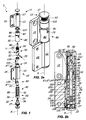
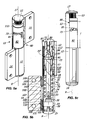
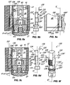
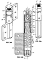
FIG. 1 is an exploded view of a first embodiment of thehinge device 1; -
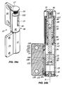
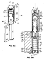
FIGs. 2a and 2b are respectively axonometric and axially sectioned views of the first embodiment of thehinge device 1 ofFIG. 1 , wherein the second tubular half-shell 13 is in the closed position; -
FIGs. 3a and 3b are respectively axonometric and axially sectioned views of the first embodiment of thehinge device 1 ofFIG. 1 , wherein the second tubular half-shell 13 is in a partially open position with the connectingplate 15 is substantially perpendicular to the connectingplate 14 of the first fixed tubular half-shell 12 and wherein thestop screw 90 is in the rest position; -
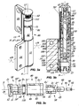
FIG. 3c is an axially sectioned exploded view of some details of the first embodiment of thehinge device 1 ofFIG. 1 ; -
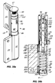
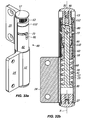
FIGs. 4a and 4b are respectively axonometric and axially sectioned views of the first embodiment of thehinge device 1 ofFIG. 1 , wherein the second tubular half-shell 13 is in a partially open position with the connectingplate 15 substantially perpendicular to the connectingplate 14 of the first fixed tubular half-shell 12 and wherein thestop screw 90 is in working position to block the sliding of theelongated element 60; -
FIG. 4c is an axially sectioned enlarged view of some details of the first embodiment of thehinge device 1 ofFIG. 1 ; -
FIGs. 5a, 5b and 5c are respectively axonometric, axially sectioned and side views of the first embodiment of thehinge device 1 ofFIG. 1 , wherein the second tubular half-shell 13 is in the fully open position with the connectingplate 15 substantially coplanar with the connectingplate 14 of the first fixed tubular half-shell 12; -
FIGs. 6a, 6b and 6c are axonometric views of thehinge device 1 ofFIG. 1 which show the position of thepin 73 relative to both thebushing 80 and thepivot 50 respectively in the closed positions ofFIGS. 3a and 3b , in the partially open position ofFIGS. 4a and 4b and in the of fully open position ofFIGS. 5a, 5b and 5c ; -
FIG. 7 is a partially exploded, broken axonometric view of thehinge device 1 ofFIG. 1 , which ahows the coupling between the second movable tubular half-shell 13 and the bushing 80; -
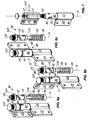
FIGs. 8a and 8c are enlarged sectioned views of some details of the first embodiment of thehinge device 1 ofFIG. 1 , with respectively inFIGs. 8b and 8d an enlargement of a first embodiment of the regulatingmember 130 respectively in the of work and rest positions; -
FIG. 8e is a sectioned, enlarged and broken view of some details of the first embodiment of thehinge device 1 ofFIG. 1 , which shows theseat 108 of thechannel 100; -
FIG. 8f is an axonometric view of the regulatingmember 130 ofFIG. 8a and 8b ; -
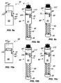
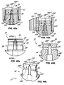
FIGs. 9a to 15c are side views of some embodiments of the bushing 80, wherein for each embodiment of the latter two axonometric views show the position of thepin 73, theplunger member 30 and the elastic counteracting means 40 in the closed and fully open positions of the second tubular half-shell 13; -
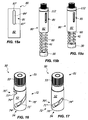
FIGs. 16 and 17 are axonometric views of some embodiments of thepivot 50, wherein the actuating passing-trough element 72 constits of a singlehelical portion 71', 71" having a constant inclination or helical pitch, thehelical portion 71', 71" being wound respectively for 180° and 90° around the axis X; -
FIGs. 18a to 18c are further side views of another embodiment of the bushing 80, which show two axonometric views of the position of thepin 73, theplunger member 30 and the elastic counteracting means 40 in the closed and fully open positions of the the second tubular half-shell 13; -
FIGs. 19a to 19d are further side views of another embodiment of the bushing 80, which show three axonometric views of the position of thepin 73, theplunger member 30 and the elastic counteracting means 40 in the closed, partially open and fully open positions of the second tubular half-shell 13; -
FIG. 20 is an exploded axonometric view of a third embodiment of thehinge device 1, wherein thehydraulic circuit 100 is partially located within theend cap 27, which is not part of the present invention; -
FIGs. 21a, 21b and 21c are axially sectioned views of thehinge device 1 ofFIG. 20 respectively in the closed, partially open with thestop screw 90 in the working position and completely open positions; -
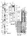
FIG. 22 is an exploded view of a fourth embodiment of thehinge device 1; -
FIGs. 23a and 23b are respectively axonometric and axially sectioned views of the embodiment of thehinge device 1 ofFIG. 22 , wherein the second tubular half-shell 13 is in the closed position; -
FIGs. 24a and 24b are respectively axonometric and axially sectioned views of the embodiment of thehinge device 1 ofFIG. 22 , wherein the second tubular half-shell 13 is in a partially open position with the connectingplate 15 substantially perpendicular to the connectingplate 14 of the first fixed tubular half-shell 12; -
FIGs. 25a and 25b are respectively axonometric and axially sectioned views of the embodiment of thehinge device 1 ofFIG. 22 , wherein the second tubular half-shell 13 is in the fully open position with the connectingplate 15 substantially coplanar with the connectingplate 14 of the first fixed tubular half-shell 12; -
FIG. 26 is an exploded view of a fifth embodiment of thehinge device 1; -
FIGs. 27a and 27b are respectively axonometric and axially sectioned views of the embodiment of thehinge device 1 ofFIG. 26 , wherein the second tubular half-shell element 13 is in the closed position; -
FIGs. 28a and 28b are respectively axonometric and axially sectioned views of the embodiment of thehinge device 1 ofFIG. 26 , wherein the second tubular half-shell 13 is in a partially open position with the connectingplate 15 substantially perpendicular to the connectingplate 14 of the first fixed tubular half-shell 12; -
FIGs. 29a and 29b are respectively axonometric and axially sectioned views of the embodiment of thehinge device 1 ofFIG. 26 , wherein the second tubular half-shell 13 is in the fully open position with the connectingplate 15 substantially coplanar with the connectingplate 14 of the first fixed tubular half-shell 12; -
FIG. 30 is an exploded view of a sixth embodiment of thehinge device 1, which is not part of the present invention; -
FIGs. 31a and 31b are respectively axonometric and axially sectioned views of the embodiment of thehinge device 1 ofFIG. 30 , wherein the second tubular half-shell 13 is in the closed position; -
FIGs. 32a and 32b are respectively axonometric and axially sectioned views of the embodiment of thehinge device 1 ofFIG. 30 , wherein the second tubular half-shell 13 is in a partially open position with the connectingplate 15 substantially perpendicular to the connectingplate 14 of the first fixed tubular half-shell 12 and wherein thestop screw 90 is in the rest position; -
FIGs. 33a and 33b are respectively axonometric and axially sectioned views of the embodiment of thehinge device 1 ofFIG. 30 , wherein the second tubular half-shell 13 is in a partially open position with the connectingplate 15 substantially perpendicular to the connectingplate 14 of the first fixed tubular half-shell 12 and wherein thestop screw 90 is in the working position to block the sliding of theelongated element 60; -
FIGs. 34a, 34b and 34c are respectively axonometric, axially sectioned and side views of the embodiment of thehinge device 1 ofFIG. 30 , wherein the second tubular half-shell 13 is in the fully open position with the connectingplate 15 substantially coplanar with the connectingplate 14 of the first fixed tubular half-shell 12; -
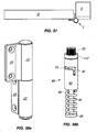
FIG. 35 is an axonometric view of a seventh embodiment of thehinge device 1; -
FIG. 36 is a partially exploded axonometric view of the seventh embodiment of thehinge device 1; -
FIG. 37 is a top view of the embodiment ofFIG. 35 wherein thehinge device 1 has the second tubular half-shell 13 is in the closed position; -
FIGs. 38a and 38b are axonometric views of thehinge device 1 ofFIG. 36 , which respectively show the relative position of the connectingplates pin 73, theplunger member 30 and the elastic counteracting means 40 in the position shown inFIG. 37 ; -
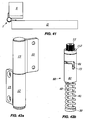
FIG. 39 is a top view of the embodiment ofFIG. 35 wherein thehinge device 1 has the second tubular half-shell 13 in a partially open position; -
FIGs. 40a and 40b are axonometric views of thehinge device 1 ofFIG. 36 , which respectively show the relative position of the connectingplates pin 73, theplunger member 30 and the elastic counteracting means 40 in the position shown inFIG. 39 ; -
FIG. 41 is a top view of the embodiment ofFIG. 35 wherein thehinge device 1 has the second tubular half-shell 13 is in the fully open position; -
FIGs. 42a and 42b are axonometric views of thehinge device 1 ofFIG. 36 , which respectively show the relative position of the connectingplates pin 73, theplunger member 30 and the elastic counteracting means 40 in the position shown inFIG. 41 ; -
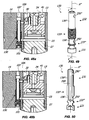
FIGs. 43a and 43b are enlarged sectional views of some details of the embodiment of thehinge device 1 ofFIG. 20 , which is not part of the present invention; -
FIGs. 44a, 44b and 44c are side, sectioned along a plane XLIV - XLIV and axonometric sectioned as above views of theend cap 27; -
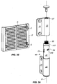
FIGs. 45a and 45b are axonometric views of another embodiment of thebushing 80; -
FIGs. 46a and 46b are axonometric views of a further embodiment of thebushing 80; -
FIGs. 47a to 47e are axonometric views of ahinge device 1 which includes the embodiment of thebushing 80 ofFIGs. 46a and 46b wherein thepin 73 is in several positions along thecam slots 81; -
FIGs. 48a and 48b are enlarged sectioned views of some details of ahinge device 1 that includes a second embodiment of the regulatingmember 130 respectively in the work and rest positions; -
FIG. 49 is an axonometric view of the second embodiment of the regulatingmember 130 ofFIGS. 48a and 48b ; -
FIG. 50 is an axonometrically sectioned view taken along a plane L - L inFIG. 49 . - With reference to the above figures, the hinge device according to the invention, generally indicated with 1, is particularly useful for rotatably moving and/or controlling a closing element D, such as a door, a shutter, a gate or the like, which can be anchored to a stationary support structure S, such as a wall and/or a door or window frame and/or a support pillar and/or the floor.
- Depending on the configuration, the
hinge device 1 according to the invention allows only the control during opening and/or closing thereof, as shown for example inFIGs. 22 to 25b or both the latter action and the automatic closing of the closing element D to which it is coupled, as shown for example inFIGs. 1 to 5c . - In general, the
hinge device 1 includes a fixedelement 10 anchored to the stationary support structure S and amovable element 11 which is anchored to the closing element D. - In a preferred, not exclusive embodiment, the fixed
element 10 may be positioned below themovable element 11. - In a preferred, not exclusive embodiment, the fixed and
movable elements shell FIGs. 3a to 5c , and a closed position, shown for example inFIGs. 2a and 2b . - Suitably, the fixed and
movable elements plates shell - Preferably, the
hinge device 1 can be configured as an "anuba"-type hinge. - Advantageously, with the exception of connecting
plates hinge device 1 may be included within the first and second tubular half-shells - In particular, the first tubular half-
shell 12 may be fixed and includes a workingchamber 20 defining the axis X and aplunger member 30 sliding therein. Appropriately, the workingchamber 20 can be closed by aclosing cap 27 inserted into the tubular half-shell 12. - As better explained later, the first fixed tubular half-
shell 12 further includes a working fluid, usually, oil, acting on thepiston 30 to hydraulically counteract the action thereof and/or elastic counteracting means 40, for example ahelical compression spring 41, acting on thesame plunger member 30. - Suitably, externally to the working
chamber 20 and coaxially therewith apivot 50 is provided, which may advantageously act as an actuator, which may include anend portion 51 and atubular body 52. Advantageously, thepivot 50 may be supported by theend portion 16 of the first fixed tubular half-shell 12. - The
end portion 51 of thepivot 50 will allow the coaxial coupling between the same and the second movable tubular half-shell 13, so that the latter and thepivot 50 unitary rotate between the open and the closed positions of the second movable tubular half-shell 13. - To this end, in a preferred, not exclusive embodiment, the
end portion 51 of thepivot 50 may include anouter surface 53 having a predetermined shape which is coupled, preferably in a removable manner, with acountershaped surface 17 of the second movable tubular half-shell 13. - In a preferred, not exclusive embodiment, shown for example in
FIG. 7 , the shapedsurface 53 may include a plurality of axial projections, susceptible to engage corresponding recesses of thecountershaped surface 17. - Preferably, the shaped
surface 53 of thepivot 50 and thecountershaped surface 17 of the second tubular half-shell 13 may be configured so as to allow the selective variation of the mutual angular position thereof. - In this way, it will be possible to change the mutual angular position of the connecting
plates FIG. 38 th. - Suitably, the
plunger member 30 and thepivot 50 may be operatively connected to each other through the elongatedcylindrical element 60, so that the rotation of the katter about the axis X corresponds to the sliding of the former along the same axis X and vice-versa. - To this end, the
elongate element 60 may include a firstcylindrical end portion 61 inserted wothin the workingchamber 20 and mutually connected with theplunger member 30 and asecond end portion 62 external to the workingchamber 20 and sliding within thetubular body 52 of thepivot 50. - The connection between the elongate
cylindrical element 60 and theplunger member 30 may be susceptible to make unitary these elements, so that they may define a slider movable along the axis X. - Advantageously, the
tubular portion 52 of thepivot 50 may have an internal diameter Di' substantially coincident with the diameter D"' of the elongatedcylindrical element 60. - The elongated
cylindrical element 60 may therefore be slidable along the axis X unitary with theplunger member 30. In other words, the elongatedcylindrical element 60 and thepivot 50 may be coupled together in a telescopic manner. - Moreover, as better explained later, depending on the configuration of the
guide cam slots 81 of thebushing 80 the cylindricalelongated element 60 with itsplunger member 30 may or may not be rotatably locked in the workingchamber 20 to prevent rotation around axis X during its sliding along the latter. - Therefore, the
plunger member 30 may slide along the axis X between an end-stroke position proximal to thepivot 50, corresponding to one of the open and closed position of the second movable tubular half-shell 13, and an end-stroke position distal from thepivot 50, corresponding to the other of the open and closed position of the second movable tubular half-shell 13. - To allow the mutual movement between the
plunger member 30 and thepivot 50, thetubular body 52 of the latter may include at least one pair ofgrooves 70', 70" equal to each other angularly spaced by 180°, each comprising at least onehelical portion 71', 71" wound around the axis X. Thegrooves 70', 70" may be communicating with each other to define a single passing-throughactuating member 72. - In
FIGs. 16 and 17 an embodiment of passing-throughactuating member 72 is shown. - Suitably, the at least one
helical portion 71', 71" may have any inclination, and may be right-handed, respectively left-handed. Preferably, the at least onehelical portion 71', 71" may be wound for at least 90° around the axis X, and even more preferably for at least 180°. - Advantageously, the at least one
helical portion 71', 71" may have a helical pitch P of 20 mm to 100 mm, and preferably of 30 mm to 80 mm. - In a preferred, not exclusive embodiment, each of the
grooves 70', 70" may be formed by a singlehelical portion 71', 71" which may have constant inclination or helical pitch. - Conveniently, the actuating
member 72 may be closed at both ends so as to define a closed path having two end blocking points 74', 74" for thepin 73 sliding therethrough, the closed path being defined by thegrooves 71', 71". - Irrespective of its position or configuration, the rotation of the actuating
member 72 around the axis X allows the mutual movement of thepivot 50 and theplunger member 30. - To guide this rotation, a
tubular guide bushing 80 external to thetubular body 52 of thepivot 50 and coaxial thereto may be provided. Theguide bushing 80 may include a pair ofcam slots 81 angularly spaced by 180°. - To allow the mutual connection between the
pivot 50, theelongated element 60 and theguide bushing 80, thesecond end portion 62 of theelongated element 60 may include apin 73 inserted through the passing-throughactuating member 72 and thecam slots 81 to move within them. - Therefore, the length of the
pin 73 may be such as to allow this function. Thepin 73 may also define a axis Y substantially perpendicular to the axis X. - As a consequance, upon rotation of the passing-through
actuating member 72 thepin 73 is moved by the latter and guided by thecam slots 81. - As already described above, the
end portion 16 of the first tubular half-shell 12 may be capable of supporting thepivot 50. Thebushing 80, coaxially coupled with the latter, may in turn be unitary coupled with the first tubular half-shell 12, preferably at thesame end portion 16, so as to allow the coupling of the first and second tubular half-shell - Advantageously, the
tubular portion 52 of thepivot 50 may have an external diameter De' less than or possibly substantially coincident with the internal diameter Di" of thebushing 80. - Moreover, the
end portion 16 of the first tubular half-shell 12 may further include a substantiallyannular appendix 18 having outer diameter De greater than or substantially coincident with the external diameter De' of thetubular portion 52 of thepivot 50, and therefore less than or substantially coincident with the internal diameter Di" of thebushing 80. - The substantially
annular appendix 18 may further have an internal diameter Di substantially coincident with the inner diameter Di' of thetubular portion 52 of thepivot 50, and therefore substantially coincident with the diameter D"' of the elongatedcylindrical element 60. - More particularly, the substantially
annular appendix 18 may further include alower surface 21 defining the upper wall of the workingchamber 20, an upper surface 19' facing thelower portion 54 of thetubular portion 52 of thepivot 50, aninner side surface 19" facing theside wall 63 of theelongated element 60 and a cylindricalouter side surface 19"' facing theinner side wall 83 of thebushing 80 for the unitary coupling thereof with the first tubular half-shell 12. To this end, for example, thewall 19"' may be threaded, while the correspondingcoupling portion 85 of theinner wall 83 may be counterthreaded. - Preferably, the second half-
shell 13 may have a tubular inner side wall 13' facing theouter side wall 82 of thebushing 80 when the same second tubular half-shell 13 is coupled to the first tubular half-shell 12. - Thanks to one or more of the above features, the
hinge device 1 has high performance while being extremely simple to manufacture and cost-effective. - In fact, the
bushing 80 has the double function of guiding thepin 73 and of supporting as a column the second movable tubular half-shell 13 which is coupled to the closing element D. - In this way, the vertical component of the weight of the latter is loaded on the stationary support structure S while the horizontal component thereof is distributed over the entire length of the
bushing 80, without minimally loading the moving parts of thehinge device 1 and in particular thepivot 50. - This provides higher performances with respect to the devices of the prior art.
- Moreover, the first and/or the second tubular half-
shell - This allows to minimize costs and manufacturing times.
- Further, this allows to minimize or to eliminate the thermal transmission which occour in the hinges or the hydraulic door closer with metal structure, since the latter transmit to the working fluid the changes of the external temperature, which in turn change the viscosity of the same working fluid and, therefore, change the operational parameters set upon installation.
- On the other hand, the
pivot 50 and/or thebushing 80, which are more stressed during use, may be made of metallic material with a relatively high mechanical strength, for example hardened steel. - Moreover, the assembly of the hinge device is exceptionally simple, thus simplifying the manufacturing thereof.
- As mentioned above, the
bushing 80 and the second tubular half-shell 13 may be further coupled each other in a removable manner, for example by sliding the latter onto the former along the axis X and subsequent mutual engagement between the outer shapedsurface 53 and thecountershaped surface 17. - This greatly simplify the maintenance operations of the closing element D, as the same may be removed from the operative position by simple lifting it, without disassembling the
hinge device 1. - In this case, the second tubular half-shell will remain in operative position on the
bushing 80 simply thanks to the gravity force. -
FIGs. 9a to 15c and18a to 19c show, in a non-limitative manner, some embodiments of thebushing 80, which differ each other for the configuration of theguide cam slots 81. - In particular,
FIG. 9a shows abushing 80 havingguide cam slots 81 that have a first portion 84' extending parallel to the axis X and a subsequentsecond portion 84" extending perpendicularly thereto. - Both
portions 84', 84" may have a length sufficient to guide the rotation of thepivot 50, which is unitary with the second tubular half-shell 13, for 90° around the axis X. Possibly, astop portion 145 may also be provided for blocking thepin 73 in the desired position, which in the exemplary embodiment shown is at the end of thesecond portion 84". - This configuration is particularly advantageous in the embodiments of the
hinge device 1 that include the elastic means 40, and in particular thecompression spring 41. - Thanks to the particular configuration of the
guide cam slots 81, thespring 41 can be preload with its highest preloading force, so that with the same size the hinge device of the invention has a greater force than the devices of the prior art, or with the same force the hinge device of the invention has a smaller size. - In fact, when the
pin 73 slides along the first portion 84' extending parallel to the axis X, thepivot 50 in rotation about the same axis X compresses thespring 41 for 90°. When thepin 73 slides along thesecond portion 84" extending perpendicularly to the axis X, thepivot 50 continues to rotate around the same axis X but does not compress thespring 41. - This allows to preload the
spring 41 with its highest preloading force, with the above mentioned advantages. It is self-evident that in this case thespring 41 moves only when thepin 73 slides along the first portion 84'. - In this case, the
bushing 80 may be for example operatively coupled with the pivot shown inFIG. 16 , wherein the passing-throughactuating member 72 constits of a singlehelical portion 71', 71" having constant inclination or helical pitch wound for 180° around the axis X. -
FIG. 10a shows abushing 80 havingguide cam slots 81 which have a first portion 84' extending parallel to the axis X and a subsequentsecond portion 84" extending perpendicularly thereto, and differs from thebushing 80 shown inFIG. 9a for the presence of threestop portions 145 along thesecond portion 84" of theguide cam slots 81. -
FIG. 11a shows abushing 80 havingguide cam slots 81 which have a first portion 84' extending parallel to the axis X and a subsequentsecond portion 84" extending perpendicularly thereto, and differs from thebushings 80 shown inFIGS. 9a and 10a for the orientation of the samesecond portion 84" and for the sliding direction of thepin 73 through theguide cam slots 81. - In fact, in this case the
spring 41 is susceptible to push up thepin 73, unlike what occours in the embodiments shown inFIGs. 9a to 10c , in which thespring 41 pulls thepin 73 down. Theguide cam slots 81 are therefore configurated to guide thepin 73 in its path downwards, so as to load thespring 41. -
FIGs. 12a ,13a and 14a show bushings 80 havingguide cam slots 81 that have asingle portion 84 inclined or helical shaped, with predetermined angle or pitch. In this way, there are not intermediate stop points thepin 73 between the closed and the fully open position of the second half-shell 13. - This configuration is extremely advantageous in the case in which the
portion 84 has an angle or pitch opposite to the one of thehelical portions 71', 71" of the passing-throughactuating member 72. In fact, in this case the vertical component of the reaction force that thepin 73 exterts on theguide cam slots 81 upon the sliding therethrough is added to the one given by the passing-throughactuating member 72. - This allow to obtain a hinge device that with the same size has a force greater than the devices of the prior art, or with the same force to obtain a hinge device of smaller size.
-
FIG. 15a shows abushing 80 havingguide cam slots 81 having a single portion 84' substantially parallel to the axis X. -
FIG. 18a shows abushing 80 havingguide cam slots 81 that have afirst portion 84 and a subsequent second portion 84' extending perpendicularly to the axis X. Thefirst portion 84 may be inclined or helical with predetermined angle or pitch. The angle may be less than 30°, preferably less than 25° and even more preferably close to 20°, and may have angle or pitch opposite to that of thehelical portion 71', 71" of the passing-throughactuating member 72. - This allows to combine the advantages described above, for example for the
bushings 80 ofFIGs. 9a to 12a . In fact, thefirst portion 84, with its slight angle allows to preload with the highest preloading force thespring 41, while the second portion 84' allows to maximize this force upon closing or opening. In practice, a closing element D potentially without blocking points is obtained, except those in correspondence of apossible stop portions 145, which has high closing or opening force and double speed, at first slow and then fast or vice-versa. Moreover, by acting on thestop screw 90 it is possible to obtain practically any opening or closing angle between 0° and 180°. - It is understood that each of the embodiments of the
hinge device 1 shown in theFIGs. 1 to 8d and18 to 42b may include any one of thebushings 80 shown inFIGS. 9a to 15c and18a to 19c , as well aspivots 50 having the at least onehelical portion 71', 71" either right-handed or left-handed, without departing from the scope of the invention defined by the appended claims. - Regardless of the shape of the
cam slots 81, the latter may be closed at both ends so as to define a closed path having two end blocking points 87', 87" for thepin 73 sliding therethrough. -
FIGs. 45a to 46b show further embodiments of thebushing 80, in which thecam slots 81 may include a first portion 84' and asecond portion 84". - The first portion 84' may extend substantially parallel to the axis X, as shown in
FIGs. 45a and 45b , or may be slightly inclined with respect to the same axis X with opposite inclination with respect to that of thegrooves 70', 70" of thepivot 50, as shown inFIGs. 46a and 46b . - On the other hand, the
second portion 84" may extend substantially perpendicularly to the axis X. - Suitably, the first and the
second portion 84', 84" may each have a length sufficient to guide the rotation of the movable tubular half-shell 13 for 90° around the axis X. -
FIGs. 47a to 47e show ahinge device 1 that includes thebushing 80 in accordance withFIGs. 45a and 45b . -
FIG. 47a shows the position completely closed of the closing element D. Thepin 73 is in correspondence of the first end blocking point 87'. -
FIG. 47b shows the position of the closing element D at 90° with respect to the closed door position. Thepin 73 is in correspondence of anintermediate blocking point 87"'. - In correspondence of the latter a first shock-absorbing portion 287' may be provided that extends substantially parallel to the axis X in a direction concordant to the sliding direction of the
pin 73 within the first portion 84' to allow a further minimum compression of thespring 41, for example of 1-2 mm, which may correspond to a further slight rotation of the movable tubular half-shell 13. In the embodiment shown, the first shock-absorbing portion 287' guides thepin 73 so as to rotate the closing element D from 90°, which position is shown inFIG. 47b , to 120° with respect to the closed door position, as shown inFig 47c . -
FIG. 47d shows the position of closing element D at 180° with respect to the closed door position. Thepin 73 is in correspondence of thesecond blocking point 87". - In correspondence of the latter a second shock-absorbing
portion 287" may be provided to guide thepin 73 so as to rotate the closing element D from 180°, which position is shown inFIG. 47d , to 190° with respect to the door closed position, as shown inFIG. 47e . - Advantageously, the blocking points 87', 87", 87"' may include zones of the
cam slots 81 against which thepin 73 abuts during its sliding hrough thesame cam slots 81 to block the closing element D during opening and/or closing. - It is pointed out that the blocking points 87', 87", 87"' are different from the
stop portions 145, and have also different functions. - The shock-absorbing
portions 287', 287" allow to absorb the shock imparted to the closing element D by the abutment of thepin 73 against the blocking points 87', 87". - In fact, this abutment is rigidly transferred to the closing element D, with the consequent unhinging danger thereof. Therefore, the shock-absorbing
portions 287', 287" allow a further compression of thespring 41 which absorb the shock of the abutment of thepin 73 against the blocking points 87", 87"', thus avoiding the above danger. - This configuration is particularly advantageous in case of aluminum frames, so as to avoid the reciprocal torsion of the closing element D and the stationary support structure S.
- Suitably, the shock-absorbing
portions 287', 287" may have a length sufficient to allow a further minimum rotation of themovable element 11 of 5° to 15° around the axis X. - A further advantage of the above configuration is that even if the closing element D rotates beyond the open position determined by the blocking points 87", 87"', the the
spring 41 returns the same closing element D in the predetermined open position. Therefore, the action of the shock-absorbingportions 287', 287" does not affect the predetermined open position of the closing element D, which therefore is maintained over time even in the case of several shock-absorbing actions. - It is understood that both the blocking points that the shock-absorbing portions of the
cam slots 81 may be in any number without departing from the scope of the appended claims. - In order to allow a user to adjust the opening and/or closing angle of the second tubular half-
shell 13, at least onestop screw 90 may be provided having afirst end 91 susceptible to selectively interact with thesecond end portion 62 of theelongated element 60 and asecond end 92 to be operated from the outside by a user to adjust the stroke of the sameelongated element 60 along the axis X. - Preferably, the at least one
stop screw 90 can be inserted within thepivot 50 in correspondence of theend portion 51 thereof, so as to slide along the axis X between a rest position spaced from thesecond end portion 62 of theelongated element 60 and a working position in contact therewith. - In this way, it is possible to adjust the
hinge device 1 in any manner. - For example,
FIGs. 4b and33b show embodiments of thehinge device 1 in which thestop screw 90 is in working position to prevent thepin 73 to slide through thesecond portion 84" of theguide cam slot 81 of thebushing 80. Thanks to this configuration, in such embodiments thepin 73 slides between the closed and fully open position of the second half-shell 13 without any intermediate blocking point, which fully open position in this embodiments shows an angle of approximately 90° between the connectingplates - In some embodiments, such as the ones shown in
FIGs. 30 to 34c , a pair of stop screws 90, 90' may be provided, which are placed in correspondence of the respective upper and lower ends 2, 3 of thehinge device 1. - The
top stop screw 90 may have the above described features. - The lower stop screw 90' may have a first end 91' susceptible to interact selectively with the
plunger member 30 and a second end 92' to be operated from the outside by a user. - As mentioned above, the
hinge device 1 include a working fluid, as shown inFIGs. 1 to 8d and 22 to 29 b. - Such embodiments may include the elastic means 40, such as those shown in
FIGs. 1 to 8d and26 to 29c , or not include them, such as the one shown inFIGs. 22 to 25c . - In the embodiments that include the elastic means 40, the latter will ensure automatic closing or the opening of the closing element D, such as in those shown in
FIGs. 1 to 8d and26 to 29c , or simply allow theplunger member 30 to return from one of the distal or proximal positions towards the othe of the distal or proximal positions without ensuring the automatic closing or opening of the closing element D. - In the first case the elastic means 40 may include a
thrust spring 41 of relatively high force, in the second case they may include a reset spring having a relatively low force. - In the first case, the
hinge device 1 acts as a hydraulic hinge or door closer with automatic closure, while in the second case thesame hinge device 1 acts as a hydraulic damping hinge. - It is understood that the use of the
spring 41 in the dampinghinge device 1 is purely optional. For example, in the embodiment of thehinge device 1 shown inFIGs. 22 to 25b the spring is not employed. - This allows to use the entire length of the working
chamber 20, thus minimizing the bulkness. - Advantageously, the working
chamber 20 may include one ormore sealing elements 22 to prevent the leakage thereof, for example one or more o-rings. - The
plunger member 30 separates the workingchamber 20 in at least one first and at least one secondvariable volume compartment first compartment 23. - To allow the passage of the working fluid between the first and the
second compartments plunger member 30 comprises a passing-throughopening 31 and valve means, which include anon-return valve 32. - Advantageously, the
non-return valve 32 may include adisc 33 inserted with minimum clearance in asuitable housing 34 to move axially along the axis X. - Depending on the direction in which the
non-return valve 32 is mounted, it opens upon the opening or closing of the closing element D, so as to allow the passage of the working fluid between thefirst compartment 23 andsecond compartment 24 during one of the opening or closing of the closing element D and to prevent backflow thereof during the other of the opening or the closing of the same closing element D. - For the controlled backflow of the working fluid between the
first compartment 23 and thesecond compartment 24 during the other of the opening or closing of the closing element D, a suitablehydraulic circuit 100 is provided. - Suitably, the
plunger member 30 may include, or respectively may constits of, a cylindrical body tightly inserted in the workingchamber 20 and facing theinner side wall 25 thereof. Thehydraulic circuit 100 may at least partially lye within the first tubular half-shell 12, and may preferably include achannel 107 external to the workingchamber 20 which defines an axis X' substantially parallel to the axis X. - The
hydraulic circuit 100 includes at least onefirst opening 101 in thefirst compartment 23 and afurther opening 102 in thesecond compartment 24. Depending on the direction in which is mounted thevalve 32, theopenings circuit 100 or as outlet and inlet thereof. - The first tubular half-
shell 12 may have at least onefirst adjusting screw 103 having afirst end 104 which interacts with theopening 102 of thehydraulic circuit 100 and asecond end 105 which can be operated from outside by a user to adjust the flow section of the working fluid through thesame opening 102. - In the embodiments shown in
FIGs. 1 to 8d and20 to 29c , thevalve 32 opens upon opening of the closing element and closes upon closing thereof, thus forcing the working fluid to flow back through thehydraulic circuit 100. In these conditions, the opening 101 acts as inlet of thehydraulic circuit 100 while theopening 102 acts as oultet thereof. - Suitably, the
outlet 102 may be fluidly decoupled from theplunger member 30 during the whole stroke thereof. Thescrew 103 may have thefirst end 104 which interacts with theopening 102 to adjust the closing speed of the closing element. - As shown in
FIGs. 1 to 8d and22 to 25c , thehydraulic circuit 100 includes afurther opening 106 in thesecond compartment 24, which in the above mentioned example may act as a second outlet in thesecond compartment 24 for thecircuit 100. - Therefore, the
plunger member 30 is in a spatial relationship with theopenings opening 102 for the entire stroke of theplunger member 30, as mentioned above, and such as to remain fluidically coupled with theopening 106 for a first part of the stroke thereof and to remain fluidly decoupled from thesame opening 106 for a second part of the stroke of theplunger member 30. - In this way, in the above embodiment the closing element D latches towards the closed position when the second tubular half-
shell 13 is in close to the first tubular half-shell 12, or in any event when the closing element D is in the proximity of the closed position. - In the case of
valve 32 mounted on the contrary, i.e. that opens upon the closing of the closing element and closes upon the opening thereof, thecircuit 100 configured as described above allows to have two resistences during opening, a first resistance for a first angular portion of the opening of the closing element D and a second resistance for a second angular portion of the opening thereof. - In this case, upon opening of the closing element D the working fluid flows from the
second compartment 24 to thefirst compartment 23 through thechannel 107, by entering through theopenings opening 101. Upon the time of closing of the closing element D the working fluid flows from thefirst compartment 23 tosecond compartment 24 through thevalve 32. The first resistance during opening is obtained when theplunger member 30 is fluidly coupled with theopening 106 during the first part of the stroke thereof, while the second resistance during opening is obtained when theplunger member 30 is fluidly decoupled from thesame opening 106 for the second part of the stroke thereof. - The
channel 107 may include a substantiallycylindrical seat 108 in which a regulatingmember 130 is inserted, the regulatingmember 130 comprising anoperative end 131 and arod 132 coupled thereto. Therod 132 defines a longitudinal axis X" mutually parallel or coincident with the axis X' of thechannel 107. - As particularly shown in
FIG. 8e , theseat 108 may have a first cylindrical portion 109' in correspondence of theopening 102 and a secondcylindrical portion 109" in correspondence of theopening 106. - To allow the mutual coupling between the regulating
member 130 and theseat 108, therod 132 of the regulatingmember 130 may include a first and a second threadedportion 133', 133", while theseat 108 may be counterthreaded in correspondence of the first cylindrical portion 109'. Alternatively, instead of the first threaded portion 133' the regulatingmember 130 may include a ring of the Seeger type inserted trough a first countershaped cylindrical portion 109'. - However, the second
cylindrical portion 109" may advantageously be smooth, that is free of counterthread. Therefore, the first cylindrical portion 109' of theseat 108 may have a maximum diameter Dp1 greater than the one Dp2 of the secondcylindrical portion 109". - The
rod 132 has anouter surface 134 faced to both theopenings FIGs. 8a to 8f may essentially have a substantially cylindrical area 135' and aflat area 135" opposite thereto. - More particularly, the
outer surface 134 may include a third and a fourthcylindrical portion 136', 136" and a first and a secondflat portion 137', 137" opposed thereto which are respectively faced to the first and the secondcylindrical portion 109', 109" of theseat 108. - Suitably, the maximum diameter Dp4 of the fourth
cylindrical portion 136" is greater than the maximum diameter Dp3 of the third cylindrical portion 136' and may substantially coincide with the maximum diameter Dp2 of the secondcylindrical portion 109" of theseat 108. Therefore, the maximum diameter Dp3 of the third cylindrical portion 136' is less than the maximum diameter Dp1 of the first cylindrical portion 109'. - The shape of the
rod 132 may be such that the substantially cylindrical area 135' extends beyond the plane of symmetry of the regulatingmember 130. Therefore, the first and the secondflat portions 137', 137" may have respective maximum widths h', h" lower than the respective maximum diameters Dp3, Dp4 of the third and fourthcylindrical portions 136', 136". - Advantageously, the first threaded portion 133', which may be interposed between the third and fourth
cylindrical portions 136', 136", may in turn include a first cylindrical zone 138' in correspondence of the third and fourthcylindrical portions 136', 136" and a firstplanar zone 138" in correspondence of the first and secondflat portions 137', 137". - On the other hand, the second threaded
portion 133", which may be interposed between theoperative end 131 and the third cylindrical portion 136' of therod 132, may in turn include a second cylindrical zone 139' in correspondence of the third cylindrical portion 136' and a secondplanar zone 139" in correspondence of the first flat portion 137'. - Thanks to one or more of the above features, the regulating
member 130 easily allows to adjust the flow section of theopening 106 when, as in this case, the limited bulkiness of thehinge device 1 does not allow the use a "classical" radial screw. The regulatingmember 130 allows for example to adjust the force by which the closing element D latches towards the closed position, as well as to avoid the latch action, as well as to adjust or to avoid one of the resistencies during opening. - By acting on the
operative end 131, for example by using a screwdriver, a user can promote the rotation of therod 132 around the axis X" between a working position, shown for example inFIGs. 8b and 8d , and a rest position, shown for example inFIGs. 8a and 8c . - As shown in these figures, in the working position the third and fourth
cylindrical portions 136', 136" are respectively faced to the first andsecond openings outer surface 134 of therod 132 selectively obstruct theopening 106 while theother opening 101 will remain in fluid communication with thechannel 107 and theopening 102 regardless of the rest or working position of therod 132. - On the other hand, in the rest position the first and the second
flat portions 137', 137" remain respectively faced to theopenings channel 107. - It is therefore apparent that regardless the rest or working position of the regulating
member 130 theopening 101 is always in fluid communication with theopening 102, while depending from the rest or the working position of the regulatingmember 130 theopening 106 remains respectively in fluid communication or not with thesame opening 102. - Consequently, when the
adjustment member 130 is in the rest position theopening 101 remains in fluid communication with bothopenings opening 101 remains in fluid communication exclusively with theopening 102, so as to exclude for example the above mentioned latch action or double resistance during opening. - In an alternative embodiment, shown in
FIGs. 48a to 50 , the regulatingmember 130 may include an axialblind hole 240, while the third and fourthcylindrical portion 136', 136" may include a respective first and second passing-throughhole 250', 250" in mutual fluidic communication with the axialblind hole 240, as particularly shown inFIG. 50 . - The operation of this embodiment is similar to that of the above described embodiment shown in
FIGs. 8a to 8f . - As shown in
FIGs. 48a and 48b , when therod 132 is in the rest position, as shown inFIG. 48b , the second passing-throughhole 250" remains fluidly coupled with theopening 106 and when therod 132 is in working position, as shown inFIG. 48a , the second passing-throughhole 250" remains fluidly decoupled from theopening 106, so as to selectively obstruct it. - Suitably, the first passing-through hole 250' may be susceptible to put in mutual fluid communication the
opening 101 and theopening 102 through thechannel 107 regardless of the rest or working position of therod 132. In fact, when the latter is in the working position, the working fluid flows in correspondence of the cylindrical portion 136' and passes through the passing-through hole 250'. - In some preferred but not exclusive embodiments, for example those shown in
FIGS. 1 to 8 and22 to 29b , thechannel 107 may pass through the connectingplate 14. - Advantageously, in such embodiments the regulating
member 130 can be inserted at one end of thechannel 107, for example the bottom one, to selectively obstruct theopening 106, while theadjustment screw 103 can be inserted at the other end of thesame channel 107, for example the upper one, to selectively obstruct theopening 102. - More particularly, the regulating
member 130 and theadjustment screw 103 can be inserted into thechannel 107 so that the axis X' of the latter coincides with the fourth axis X" of the regulatingmember 130 and with the fifth axis X"' of the adjustingscrew 103. It is understood that the axes X', X" and X"' are substantially parallel to the axis X. - In this way, the
operative end 131 of the regulatingmember 130 and theoperative end 105 of the adjustingscrew 103 can be accessible by the user at opposite sides with respect to a median plane πM, shown for example inFIG. 3a , passing through the connectingplate 14 and substantially perpendicular to the axes X', X" and X"', and consequently perpendicular to the axis X. - Thanks to this configuration, it is possible to obtain both the adjustment of the closing and/or opening speed of the closing element D (by acting on the adjustment screw 103) and the force of the latch action and/or of the resistances during opening (by acting on the regulating member 130) with minimum bulkiness and round shapes, typical of the "Anuba"-type hinges.
- In some preferred but not exclusive embodiments, for example those shown in
FIGs. 20 to 21c and43a to 44c , theclosing cap 27 of the workingchamber 20 may include a passing-through duct 100' and a substantially annularperipheral groove 29 around the substantiallycylindrical side wall 28 of thesame cap 27. Once thecap 27 is inserted in the workingchamber 20, its substantiallycylindrical side wall 28, and therefore theperipheral groove 29, remains faced theinner side wall 25 of the same workingchamber 20. - Conveniently, the
peripheral groove 29, which may have facingside walls 29', 29" and abottom wall 29"', may be open at the top so that thebottom wall 29"' and theinner side wall 25 of the workingchamber 20 remain directly faced each other. - The passing-through duct 100' may include a pair of
first branches 140', 140" havingrespective openings 100 fluidly communicating with thechannel 107 through theperipheral groove 29 and theopening 101 passing through the second half-shell 12 and asecond branch 141 with anopening 100"' fluidly communicating with thefirst compartment 23. - A
central manifold 100"" may lye in a substantially central position along the X axis between thefirst branches 140', 140" and thesecond branch 141, whichcentral manifold 100"" is therefore in fluid communication with both thechannel 107 that thefirst compartment 23. - Advantageously, the
cap 27 may include theadjustment screw 103 preferably in axial position along the axis X. Thescrew 103 may have theend 104 interacting with thecentral manifold 100"" and theoperative end 105 to be operated from the outside by a user to adjust the flow section of the working fluid therethrough. - In the embodiment shown in
FIGs. 20 to 21c and43a to 44c , in which the valve means 32 are configured to allow the passage of the working fluid between thefirst compartment 23 andsecond compartment 24 during the opening of the closing element D and to prevent the backflow thereof during the closing of the same closing element D, thesingle screw 103 is susceptible to adjust the closing speed of the closing element D. - Thanks to one or more of the above features, it is possible to obtain a simple and quick adjustment even in
hinge devices 1 having minimum dimensions or completely round shaped, where it is not possible to insert screws neither axially nor radially. - Moreover, the peripheral
annular channel 29 allows to simplify the mounting of thehinge device 1, while improving the reliability thereof. - As mentioned above, some embodiments of the
hinge device 1 may include the elastic counteracting means 40, such as those shown inFIGs. 1 to 8d ,20 to 21c and26 to 34c . - Such embodiments may include the working fluid, such as those shown in
FIGs. 1 to 8d ,20 to 21c and26 to 29c , or not, such as that shown inFIGs. 30 to 34c . - In the latter case, the
hinge device 1 acts as a purely mechanical opening/closing hinge. - In some preferred but not exclusive embodiments, for example those shown in
FIGs. 1 to 8d ,20 to 21c and30 to 34c , thespring 41 and theplunger member 30 may be coupled to each other so that the former 41 is in the position of maximum elongation in correspondence of the end-stroke distal position of the latter. In this case, thespring 41 may be interposed between thecylindrical portion 52 of thepivot 50 and theplunger member 30. - In order to minimize the friction between the moving parts, at least one antifriction member may be provided, such as an
annular bearing 110, interposed between thepivot 50 and theend portion 16 of the first tubular half-shell 12 for the supporting thereof. - In fact, in the above mentioned embodiment the
pin 73 will be pulled downwards, thus urging downwards also thepivot 50 which therefore rotate about the axis X on thebearing 110. Suitably, the pin loads the stresses due to the action of thespring 41 on thelatter bearing 110. - In other preferred but not exclusive embodiments, such as the one shown in
FIGs. 26 to 29c , thespring 41 and theplunger member 30 may be coupled to each other so that the first is in the position of maximum elongation in correspondence of the proximal end-stroke position of theplunger member 30. In this case, thespring 41 may be interposed between thebottom wall 26 of the workingchamber 20 and theplunger member 30. - In this case, to minimize the friction between the moving parts at least one antifriction member may be provided, for example a further
annular bearing 111, interposed between thepivot 50 and theupper wall 121 of asleeve 120 susceptible to retain thepivot 50, whichsleeve 120 being unitary coupled externally to thebushing 80 coaxially therewith. - In fact, with the above configuration the
pin 73 is urged upwards, by urging in turn upwords thepivot 50 which therefore rotate about the axis X on thebearing 111. The retainingsleeve 120 may for example be screwed into the lower portion of thebushing 80, so as to retain thepivot 50 in the operative position. - In any case, the
hinge device 1 can be configured to minimize friction between the moving parts. - For this purpose, at least one antifriction member may be provided, for example a further
annular bearing 112, interposed between thebushing 80 and the second tubular half-shell 13, in such a manner that the latter rotates around the axis X on thebearing 112. - Therefore, the
bushing 80 may suitably have acentral opening 86 in the proximity of theupper portion 87 for insertion of theend portion 51 of thepivot 50. More particularly, thebushing 80 and thepivot 50 may be mutually configured so that once thepivot 50 is inserted within thebushing 80 theend portion 51 of the former passes through thecentral opening 86 of the latter. - To this end, the
bushing 80 may have a height h substantially equal to the sum of the height of thebearing 110, thetubular body 52 of thepivot 50 and itscoupling portion 85 with theouter side wall 19"' of theannular appendix 18. - Therefore, the
bearing 112 rests on theupper portion 87, so that the closing element does not load at all thepivot 50 during its rotation about the axis X. In fact, the weight of the closing element D is loaded on thebearing 112. - Moreover, the,position of the
pivot 50 within thebushing 80 prevents misalignment and/or slipping out of thesame pivot 50 due to forces pushing the same upwards, for example in the case of a user that force in closing the closing element D. In fact, in this case thepivot 50 impacts against theupper portion 87 of thebushing 80, such as clearly visible inFIGs. 32b and33b , thus remaining in its original position. - Moreover, the
bushing 80 and the second tubular half-shell 13 may be preferably in a spatial relationship to each other such that the second tubular half-shell 13 once coupled with thebushing 80 remains spaced from the first tubular half-shell 12, for example by a distance d of few tenths of a millimeter. - From the above description, it is apparent that the invention fulfils the intended objects.
- The invention is susceptible to many changes and variants. All particulars may be replaced by other technically equivalent elements, and the materials may be different according to the needs, without exceeding the scope of the invention defined by the appended claims.
Claims (15)
- A hinge device for rotatably moving and/or controlling during closing and/or opening a closing element (D), such as a door, a shutter or the like, anchored to a stationary support structure (S), such as a wall or a frame, the device including:- a fixed element (10) anchored to the stationary support structure (S);- a movable element (11) anchored to the closing element (D), said movable element (11) and said fixed element (10) being mutually coupled to rotate about a first longitudinal axis (X) between an open position and a closed position;- at least one slider (30, 60) movable along a second axis (X) between a first end-stroke position, corresponding to one of said open and closed positions, and a second end-stroke position, corresponding to the other of said open and closed positions;wherein one of said fixed element (10) and movable element (11) comprises at least one working chamber (20) defining said second longitudinal axis (X) for slidably housing said at least one slider (30, 60), the other of said fixed element (10) and movable element (11) comprising a pivot (50) defining said first axis (X), said pivot (50) and said at least one slider (30, 60) being mutually coupled so that the rotation of the movable element (11) around said first axis (X) corresponds to the at least partly sliding of the at least one slider (30, 60) along said second axis (X) and vice-versa;
wherein said at least one working chamber (20) includes a working fluid acting on said at least one slider (30, 60) to hydraulically counteract the action thereof, said at least one slider (30, 60) including a plunger member (30) susceptible to separate said working chamber (20) in at least one first and at least one second variable volume compartment (23, 24) fluidly communicating and preferably adjacent each other, said plunger member (30) comprising a passing-through opening (31) to put in fluid communication said first compartment and said second variable volume compartments (23, 24) and valve means (32) interacting with said opening (31) to allow the passage of the working fluid between said first compartment (23) and said second compartment (24) during one of the opening or closing of the closing element (D) and to prevent the backflow thereof during the other during the opening or closing of the same closing element (D), a hydraulic circuit (100) being provided to allow the passage of the working fluid between said first compartment (23) and said second compartment (24) during the other of the opening or closing of the closing element (D);
wherein said hydraulic circuit (100) includes at least one channel (107) external to said working chamber (20) defining a third axis (X') substantially parallel to said second axis (X), said channel (107) having at least one first opening (101) in said first compartment (23) and at least one second opening (106) in said second compartment (24) which is proximal to said first opening (101), said channel (107) further including a third opening (102) in said second compartment (24) distal from said first opening (101);
wherein said plunger member (30) is in a spatial relationship with said second and third openings (106, 102) of said circuit (100) such as to remain fluidly decoupled from said third opening (102) for the entire stroke of the plunger member (30) and such as to remain fluidly coupled with said second opening (106) for a first part of said stroke and to remain fluidly decoupled therefrom for a second part of said stroke;
wherein at least one first regulating member (130) for regulating the flow of said working fluid between said first compartment (23) and said second compartment (24) is further provided, said at least one first regulating member (130) including a rod (132) defining a fourth longitudinal axis (X") having an outer surface (134) facing said first opening (101), said at least one first regulating member (130) being inserted in said at least one channel (107) so that said third and fourth axis (X', X") are substantially parallel or coinciding each other,
characterised in that the outer surface (134) of said at least one first regulating member (130) includes at least one first portion (234') facing said first opening (101) and at least one second portion (234") facing said second opening (106), said at least one first regulating member (130) further including at least one operative end (131) to be operated from the outside by a user to promote the rotation of said rod (132) about said fourth axis (X") between a working position in which said at least one second portion (234") of the outer surface (134) of the same at least one first regulating member (130) selectively obstructs said second opening (106) and a rest position in which the latter and said channel (107) are in mutual fluid communication, said at least one first portion (234') of the outer surface (134) of said at least one first regulating member (130) being configured and/or dimensioned so that said first opening (101) and said third opening (102) are always in mutual fluid communication through said channel (107) regardless the rod (132) is in the rest position or in the working position. - Device according to claim 1, wherein said channel (107) includes a substantially cylindrical seat (108) for said at least one first regulating member (130) that includes said first and said second opening (101, 106), said seat (108) having a first cylindrical portion (109') at said first opening (102) having a first maximum diameter (Dp1) and a second cylindrical portion (109") at said second opening (106) having a second maximum diameter (Dp2), said at least one first and at least one second portions (234', 234") of the outer surface (134) of said at least one regulating member (130) including a respective third and fourth cylindrical portion (136', 136") each having a respective maximum diameter (Dp3, Dp4) lying respectively in said first and second cylindrical portion (109', 109") of said seat (108).
- Device according to claim 2, wherein said fourth cylindrical portion (136") has a maximum diameter (Dp4) substantially coinciding with the maximum diameter (Dp2) of said second cylindrical portion (109', 109") of said seat (108), said third cylindrical portion (136') having a maximum diameter (Dp3) lower than the maximum diameter (Dp1) of the first cylindrical portion (109') of said seat (108).
- Device according to claim 2 or 3, wherein said at least one first and at least one second portions (234', 234") of the outer surface (134) of said at least one first regulating member (130) have a respective first and second flat portions (137', 137") respectively opposite to said third and fourth cylindrical portion (136', 136") so that when said rod (132) is in said rest position said first and second flat portions (137', 137") remain respectively faced to said first and said second openings (101, 106) and when said rod (132) is in said working position said third and fourth cylindrical portions (136', 136") remain respectively faced to said first and said second openings (101, 106) so as to selectively obstruct the latter.
- Device according to the preceding claim, wherein said first and second flat portions (137', 137") have respective maximum widths (h', h") lower than the respective maximum diameters (Dp3, Dp4) of said third and fourth cylindrical portions (136', 136").
- Device according to one or more of claims 1 to 3, wherein said at least one regulating member (130) includes an axial blind hole (240), said third and fourth cylindrical portions (136', 136") of said at least one regulating member (130) including a respective first and second passing-through hole (250', 250") in mutual fluid communication with said axial blind hole (240) so that when said rod (132) is in said rest position said second passing-through hole (250") remains fluidly coupled with said second opening (106) and when said rod (132) is in said working position said second passing-through hole (250") remains fluidly decoupled from said second opening (106) so as to selectively obstruct it, said first passing-through hole (250') being anyhow susceptible to put in mutual fluid communication said first opening (101) and said third opening (102) through said channel (107) regardless the rod (132) is in the rest position or in the working position.
- Device according to any one of claims 1 to 6, wherein said at least one first regulating member (130) includes at least one first threaded portion (133') interposed between said third and fourth cylindrical portions (136', 136"), said first cylindrical portion (109') being counterthreaded, said second cylindrical portion (109") being smooth.
- Device according to the preceding claim, wherein said at least one first threaded portion (133') includes a cylindrical zone (138') in correspondence of the third and fourth cylindrical portion (136', 136") and a flat zone (138") in correspondence of the first and second flat portions (137', 137") of the outer surface (134) of said at least one first regulating member (130).
- Device according to any one of the preceding claims, wherein said valve means (32) are configured to allow the passage of the working fluid between said first compartment (23) and said second compartment (24) during opening of the closing element (D) and to prevent backflow thereof during closing thereof, said channel (107) allowing the passage of the working fluid between said first compartment (23) and said second compartment (24) during closing of the closing element (D), said plunger member (30) being susceptible to impart a latch action to the closing element (D) when said movable element (11) is in proximity of the closed position.
- Device according to any one of claims 1 to 8, wherein said valve means (32) are configured to allow the passage of the working fluid between said first compartment (23) and said second compartment (24) during closing, respectively during opening, of the closing element (D) and to prevent the backflow thereof during opening, respectively during closing, of the same closing element (D), said channel (107) allowing the passage of the working fluid between said first compartment (23) and said second compartment (24) during opening, respectively during closing, of the closing element (D), said plunger member (30) being in a spatial relationship with said second and third openings (102, 106) of said channel (107) such that the closing element (D) has a first resistance during closing, respectively during opening, for a first part of the angular rotation of the movable element (11) around said first axis (X) corresponding to said first part of said stroke of said plunger member (30) and a second resistance during closing, respectively during opening, for a second part of the angular rotation of the movable element (11) around said first axis (X) corresponding to the second part of said stroke.
- Device according to any one of the preceding claims, wherein said at least one working chamber (20) further includes elastic counteracting means (40) located in said second compartment (24) acting on said at least one slider (30, 60) for returning thereof from one of said first and second end-stroke positions towards the other of said first and second end-stroke positions, said elastic counteracting means (40) being movable between a position of maximum and minimum elongation.
- Device according to one or more of the preceding claims, wherein said fixed element (10) comprises a first lower tubular half-shell (12) which includes said working chamber (20), said movable element (11) comprising a second upper tubular half-shell (13), the latter being mutually superimposed to said first tubular lower half-shell (12) to rotate about said first longitudinal axis (X) between an open position and a closed position, said pivot (50) being external to said working chamber (20) and coaxially coupled to said second upper tubular half-shell (13) to rotate unitary therewith between said open and closed positions, said pivot (50) including a tubular body (52), said plunger member (30) being operatively connected to said pivot (50) and inserted into said working chamber (20) to slide along said first axis (X) between an end-stroke position proximal to said pivot (50), corresponding to one of the first and the second end-stroke positions of the at least one slider (30, 60), and a end-stroke position distal therefrom, corresponding to the other of the first and the second end-stroke positions of the at least one slider (30, 60).
- Device according to the preceding claim, wherein said at least one slider (30, 60) includes a cylindrical element (60) elongated along said axis (X) having a first end portion (61) inserted into said working chamber (20) mutually connected with said plunger member (30) and a second end portion (62) external to the working chamber (20) sliding within the tubular body (52) of said pivot (50), a tubular bushing (80) having a pair of guide cam slots (81) angularly spaced by 180° being provided, said tubular bushing (80) being coaxially lying externally to said tubular body (52) of said pivot (50), the latter (50) including at least one pair of grooves (70', 70") equal to each other angularly spaced by 180° each comprising at least one helical portion (71', 71") wound around said axis (X), said grooves (70', 70") being communicating with each other to define an passing-through actuating member (72).
- Device according to the preceding claim, wherein said second end portion (62) of said elongated element (60) includes a pin (73) inserted in said passing-through actuating member (72) and in said guide cam slots (81) to slide therethrough, so as to reciprocally engage said pivot (50), said elongated cylindrical element (60) and said bushing (80), said first lower tubular half-shell (12) including an upper end portion (16) for rotatably supporting said pivot (50), said bushing (80) and said first lower tubular half-shell (12) being unitary coupled to each other so as to allow said guide cam slots (81) to guide the movement of said pin (73) actuated by said passing-through actuating member (72), said second upper tubular half-shell (13) and said bushing (80) being coaxially coupled each other so that the latter (80) defines the rotation axis of the first (13).
- Device according to the preceding claim, wherein said bushing (80) and said second tubular half-shell (13) are mutually coupled.in a removable manner by mutual sliding along said axis (X).
Priority Applications (4)
| Application Number | Priority Date | Filing Date | Title |
|---|---|---|---|
| PL13792483T PL2785943T3 (en) | 2012-10-04 | 2013-10-04 | Hinge device for doors, shutters and the like |
| SI201330073T SI2785943T1 (en) | 2012-10-04 | 2013-10-04 | Hinge device for doors, shutters and the like |
| HRP20150993TT HRP20150993T1 (en) | 2012-10-04 | 2015-09-21 | Hinge device for doors, shutters and the like |
| CY20151100915T CY1116790T1 (en) | 2012-10-04 | 2015-10-09 | Hinged Joint Arrangement for Doors, Exterior Window Sheets and Other Related Items |
Applications Claiming Priority (3)
| Application Number | Priority Date | Filing Date | Title |
|---|---|---|---|
| IT000254A ITVI20120254A1 (en) | 2012-10-04 | 2012-10-04 | HINGE DEVICE FOR DOORS, DOORS OR SIMILARS |
| IT000255A ITVI20120255A1 (en) | 2012-10-04 | 2012-10-04 | HINGE DEVICE FOR DOORS, DOORS OR SIMILARS |
| PCT/IB2013/059120 WO2014054028A1 (en) | 2012-10-04 | 2013-10-04 | Hinge device for doors, shutters and the like |
Publications (2)
| Publication Number | Publication Date |
|---|---|
| EP2785943A1 EP2785943A1 (en) | 2014-10-08 |
| EP2785943B1 true EP2785943B1 (en) | 2015-08-05 |
Family
ID=49596358
Family Applications (1)
| Application Number | Title | Priority Date | Filing Date |
|---|---|---|---|
| EP13792483.3A Active EP2785943B1 (en) | 2012-10-04 | 2013-10-04 | Hinge device for doors, shutters and the like |
Country Status (24)
| Country | Link |
|---|---|
| US (1) | US9605462B2 (en) |
| EP (1) | EP2785943B1 (en) |
| JP (1) | JP6298062B2 (en) |
| CN (1) | CN104903533B (en) |
| AU (1) | AU2013326085B2 (en) |
| BR (1) | BR112015007491A2 (en) |
| CA (1) | CA2885173C (en) |
| CY (1) | CY1116790T1 (en) |
| DK (1) | DK2785943T3 (en) |
| EA (1) | EA028754B1 (en) |
| ES (1) | ES2551917T3 (en) |
| HK (1) | HK1201308A1 (en) |
| HR (1) | HRP20150993T1 (en) |
| HU (1) | HUE025894T2 (en) |
| IL (1) | IL237975B (en) |
| MX (1) | MX354681B (en) |
| NZ (1) | NZ706462A (en) |
| PL (1) | PL2785943T3 (en) |
| PT (1) | PT2785943E (en) |
| RS (1) | RS54326B1 (en) |
| SI (1) | SI2785943T1 (en) |
| UA (1) | UA115452C2 (en) |
| WO (1) | WO2014054028A1 (en) |
| ZA (1) | ZA201502090B (en) |
Families Citing this family (23)
| Publication number | Priority date | Publication date | Assignee | Title |
|---|---|---|---|---|
| UA115453C2 (en) * | 2012-10-04 | 2017-11-10 | Ін Енд Тек С.Р.Л. | Hinge device for doors, shutters and the like |
| US9982470B2 (en) * | 2012-11-09 | 2018-05-29 | Ford Global Technologies, Llc | Soft close mechanism for a closure |
| CN103967367B (en) * | 2013-01-24 | 2016-08-17 | 陈政 | A kind of buffered gate folding |
| ITVI20130245A1 (en) * | 2013-10-04 | 2015-04-05 | In & Tec Srl | HINGE DEVICE FOR DOORS, DOORS OR SIMILARS |
| DE102014215902A1 (en) * | 2014-08-11 | 2016-02-11 | Suspa Gmbh | Damping hinge for damping hinge pivoting about a hinge pivot axis |
| CN107780744A (en) * | 2016-08-31 | 2018-03-09 | 赵芬 | Angle positioning and self-closing hinge can be adjusted |
| CN105370130B (en) * | 2015-12-10 | 2017-01-25 | 湖州职业技术学院 | Hydraulic damping force adjusting mechanism for hydraulic hinge |
| CN205400375U (en) * | 2016-01-05 | 2016-07-27 | 希美克(广州)实业有限公司 | Hydraulic pressure door closer with high temperature decompression function |
| US10477986B2 (en) | 2016-01-11 | 2019-11-19 | Hussmann Corporation | Fan plenum assembly and attachment in a merchandiser |
| CN105781301B (en) * | 2016-04-12 | 2017-08-11 | 燕山大学 | Automatically it can close and rotate freely the door-hinge of positioning |
| EP3342965A1 (en) * | 2016-12-27 | 2018-07-04 | Locinox | Hydraulically damped, self closing hinge |
| US10738520B2 (en) * | 2017-06-26 | 2020-08-11 | Ford Global Technologies, Llc | Door hinge with integrated detent and stop |
| JP6758785B2 (en) * | 2018-04-25 | 2020-09-23 | スガツネ工業株式会社 | Hinge device |
| JP7320858B2 (en) * | 2018-05-03 | 2023-08-04 | ファルジア,ニコラウス | damped hinge assembly |
| KR20210034062A (en) * | 2018-07-23 | 2021-03-29 | 산둥 메이예 오토메이션 테크놀로지 컴퍼니 리미티드 | Hinge plate structure |
| CN108982364A (en) * | 2018-09-12 | 2018-12-11 | 钢研纳克检测技术股份有限公司 | A kind of multifunctional sample room for spectrum analysis |
| US11041335B2 (en) * | 2018-12-12 | 2021-06-22 | Waterson Corp. | Hinge |
| IT201900004791A1 (en) * | 2019-03-29 | 2020-09-29 | Colcom Group S P A | HINGE DEVICE FOR GLASS DOORS OR SIMILAR |
| CN109930934B (en) * | 2019-04-10 | 2024-04-26 | 徐振溪 | Automatic door and window closing unit and bidirectional balance door and window unit manufactured by using same |
| IT201900016223A1 (en) * | 2019-09-13 | 2021-03-13 | Colcom Group S P A | HINGE DEVICE FOR THE REVOLVING MOVEMENT OF A DOOR OR LEAF |
| EP4111023A1 (en) * | 2020-02-28 | 2023-01-04 | Locinox | A dashpot for damping a closing movement of a closure system |
| WO2021170870A1 (en) * | 2020-02-28 | 2021-09-02 | Locinox | A hydraulically damped hinge for hinging a closure member to a support |
| US20230304346A1 (en) * | 2022-03-23 | 2023-09-28 | Moshun, LLC | Systems and devices for motion control |
Family Cites Families (44)
| Publication number | Priority date | Publication date | Assignee | Title |
|---|---|---|---|---|
| US491898A (en) * | 1893-02-14 | Spring-hinge and check | ||
| US424613A (en) * | 1890-04-01 | boeeis | ||
| US424614A (en) * | 1890-04-01 | James willard morris | ||
| GB191019477A (en) | 1910-08-19 | 1911-08-03 | Frederick Langtry Van Allen | Improvements in Hinges. |
| US1241083A (en) * | 1914-05-28 | 1917-09-25 | Emil Bommer | Checking-hinge. |
| US1134510A (en) * | 1914-07-14 | 1915-04-06 | Charles H Busch | Door-check hinge. |
| US1139822A (en) * | 1915-01-11 | 1915-05-18 | August Sundh | Gate-hinge. |
| US1200538A (en) * | 1915-09-03 | 1916-10-10 | Allen Andrew Smith | Hinge. |
| US1423784A (en) * | 1921-03-02 | 1922-07-25 | Vuille George | Hinge check |
| US2018564A (en) * | 1932-03-30 | 1935-10-22 | Milly Lucien Charles Eugene | Hinge with hydraulic brake |
| GB401858A (en) | 1932-09-24 | 1933-11-23 | William Henry Tonks | Improvements relating to door hinges |
| US2015988A (en) * | 1933-01-04 | 1935-10-01 | Bommer Gustav | Door check and closer |
| US2103660A (en) * | 1934-12-26 | 1937-12-28 | Bommer Gustav | Door check and closer |
| US2027170A (en) * | 1935-05-20 | 1936-01-07 | Marcus B Hemingway | Doorcheck |
| US2118950A (en) * | 1936-05-20 | 1938-05-31 | Leavelle Ab | Closure controlling device |
| US2127327A (en) * | 1936-07-23 | 1938-08-16 | Dutee W Flint | Automatic door check construction |
| GB1516622A (en) | 1977-03-02 | 1978-07-05 | Schubeis E | Self-closing hinge |
| JPS5947794B2 (en) * | 1980-02-21 | 1984-11-21 | 哲雄 池田 | door check device |
| GB8618668D0 (en) | 1986-07-31 | 1986-09-10 | Nouveaux Security Products Ltd | Door operating mechanism |
| JPH0755254Y2 (en) | 1989-07-06 | 1995-12-20 | リョービ株式会社 | Floor hinge hydraulic control mechanism |
| US5222277A (en) * | 1992-03-31 | 1993-06-29 | Aec-Able Engineering Co., Inc. | Intermittently and reversibly operable hot wax energized hinge |
| US5572768A (en) * | 1994-04-13 | 1996-11-12 | Enidine Incorporated | Door closer |
| WO2000061903A1 (en) * | 1999-03-19 | 2000-10-19 | Doorsoft Co.,Ltd. | Vertical type door closer |
| KR200190938Y1 (en) * | 2000-03-06 | 2000-08-01 | 민병덕 | Door-hinge device having auto-locking function |
| WO2002055821A1 (en) * | 2001-01-15 | 2002-07-18 | Sawa, Masako | Automatic closing door hinge, automatic closing door mechanism, and hinge of automatic closing door mechanism |
| KR100456786B1 (en) | 2002-02-07 | 2004-11-10 | 주식회사 에스엔드씨테크 | Hinge for Auto-Closing Door |
| EP1398442A1 (en) * | 2002-08-20 | 2004-03-17 | KL-Beschläge Karl Loggen GmbH | Drive for a movable element |
| US6966150B2 (en) | 2003-04-11 | 2005-11-22 | Fanny Chiang | Adjustable automatic positioning hinge for glass doors |
| US7155776B2 (en) | 2003-06-10 | 2007-01-02 | I-One Innotech Co., Ltd. | Multipurpose hinge apparatus having automatic return function |
| GB2406879A (en) * | 2003-10-09 | 2005-04-13 | Graham Chesworth | Hinge |
| KR100644009B1 (en) * | 2004-08-20 | 2006-11-10 | 주식회사 아이원이노텍 | Slim Type Hinge Apparatus Having Automatic Return Function |
| KR100586262B1 (en) | 2004-08-24 | 2006-06-07 | 주식회사 아이원이노텍 | Hinge Apparatus for Heavy Door Having Automatic Return Function |
| KR101071909B1 (en) * | 2004-09-03 | 2011-10-11 | 이미재 | Hydraulic controlled shock-absorbing hinge |
| US7243394B2 (en) * | 2005-02-22 | 2007-07-17 | Ching Chih Kao | Door closing hinge device |
| KR100835730B1 (en) | 2005-07-29 | 2008-06-05 | 주식회사 아이원이노텍 | Ball Type Clutch Apparatus and Hinge Apparatus Having Automatic Return Function Using the Same |
| KR100762785B1 (en) * | 2005-10-20 | 2007-10-02 | 전병수 | Oil pressure door hinge |
| US7305797B2 (en) | 2006-03-31 | 2007-12-11 | Fanny Chiang | Door-closing assembly of frameless glass door |
| KR100761904B1 (en) * | 2006-08-08 | 2007-09-28 | 주식회사 아이원이노텍 | Hinge apparatus having automatic return function for use in building materials |
| KR100776627B1 (en) | 2006-10-24 | 2007-11-15 | 주식회사 아이원이노텍 | Buried type hinge apparatus having automatic return function |
| ITMI20071095A1 (en) | 2007-05-30 | 2008-11-30 | Beretta Brevetti S R L | HINGE |
| WO2009069237A1 (en) * | 2007-11-27 | 2009-06-04 | Sawa Corporation | Automatic door closing hinge and double swing door structure |
| JP4651684B2 (en) * | 2008-02-05 | 2011-03-16 | 株式会社サワ | Automatic door hinge for double opening and double door structure |
| KR100874633B1 (en) | 2008-04-01 | 2008-12-17 | 주식회사 아이원이노텍 | Hinge apparatus separated type with return function |
| CN101705775B (en) | 2009-10-10 | 2012-09-12 | 上海洋洋大多利特殊钉有限公司 | Automatic-closing door hinge |
-
2013
- 2013-04-10 UA UAA201504198A patent/UA115452C2/en unknown
- 2013-10-04 DK DK13792483.3T patent/DK2785943T3/en active
- 2013-10-04 PL PL13792483T patent/PL2785943T3/en unknown
- 2013-10-04 HU HUE13792483A patent/HUE025894T2/en unknown
- 2013-10-04 MX MX2015004278A patent/MX354681B/en active IP Right Grant
- 2013-10-04 SI SI201330073T patent/SI2785943T1/en unknown
- 2013-10-04 RS RS20150634A patent/RS54326B1/en unknown
- 2013-10-04 AU AU2013326085A patent/AU2013326085B2/en not_active Ceased
- 2013-10-04 BR BR112015007491A patent/BR112015007491A2/en not_active Application Discontinuation
- 2013-10-04 US US14/430,218 patent/US9605462B2/en active Active
- 2013-10-04 PT PT137924833T patent/PT2785943E/en unknown
- 2013-10-04 CA CA2885173A patent/CA2885173C/en active Active
- 2013-10-04 EP EP13792483.3A patent/EP2785943B1/en active Active
- 2013-10-04 CN CN201380051677.1A patent/CN104903533B/en active Active
- 2013-10-04 NZ NZ706462A patent/NZ706462A/en not_active IP Right Cessation
- 2013-10-04 EA EA201590680A patent/EA028754B1/en unknown
- 2013-10-04 WO PCT/IB2013/059120 patent/WO2014054028A1/en active Application Filing
- 2013-10-04 ES ES13792483.3T patent/ES2551917T3/en active Active
- 2013-10-04 JP JP2015535157A patent/JP6298062B2/en active Active
-
2015
- 2015-02-18 HK HK15101811.8A patent/HK1201308A1/en not_active IP Right Cessation
- 2015-03-26 IL IL237975A patent/IL237975B/en not_active IP Right Cessation
- 2015-03-26 ZA ZA2015/02090A patent/ZA201502090B/en unknown
- 2015-09-21 HR HRP20150993TT patent/HRP20150993T1/en unknown
- 2015-10-09 CY CY20151100915T patent/CY1116790T1/en unknown
Also Published As
| Publication number | Publication date |
|---|---|
| US20150233164A1 (en) | 2015-08-20 |
| WO2014054028A1 (en) | 2014-04-10 |
| HUE025894T2 (en) | 2016-05-30 |
| HRP20150993T1 (en) | 2015-11-20 |
| NZ706462A (en) | 2017-11-24 |
| MX2015004278A (en) | 2016-01-20 |
| IL237975B (en) | 2019-09-26 |
| HK1201308A1 (en) | 2015-08-28 |
| AU2013326085A1 (en) | 2015-04-09 |
| JP6298062B2 (en) | 2018-03-20 |
| PT2785943E (en) | 2015-10-30 |
| US9605462B2 (en) | 2017-03-28 |
| UA115452C2 (en) | 2017-11-10 |
| MX354681B (en) | 2018-03-14 |
| CY1116790T1 (en) | 2017-03-15 |
| JP2015533967A (en) | 2015-11-26 |
| EP2785943A1 (en) | 2014-10-08 |
| ES2551917T3 (en) | 2015-11-24 |
| RS54326B1 (en) | 2016-02-29 |
| CN104903533A (en) | 2015-09-09 |
| DK2785943T3 (en) | 2015-10-12 |
| AU2013326085B2 (en) | 2017-10-19 |
| BR112015007491A2 (en) | 2017-07-04 |
| CA2885173C (en) | 2020-11-03 |
| SI2785943T1 (en) | 2016-01-29 |
| PL2785943T3 (en) | 2015-12-31 |
| IL237975A0 (en) | 2015-05-31 |
| CA2885173A1 (en) | 2014-04-10 |
| CN104903533B (en) | 2016-08-24 |
| EA201590680A1 (en) | 2015-12-30 |
| ZA201502090B (en) | 2016-01-27 |
| EA028754B1 (en) | 2017-12-29 |
Similar Documents
| Publication | Publication Date | Title |
|---|---|---|
| EP2785943B1 (en) | Hinge device for doors, shutters and the like | |
| EP3054073B1 (en) | Hinge device for doors, shutters and the like | |
| EP2694764B1 (en) | Hinge device for doors, shutters or the like | |
| CA2925684C (en) | Hinge device for doors, shutters or the like | |
| TW201534806A (en) | Hinge device for doors, shutters and the like |
Legal Events
| Date | Code | Title | Description |
|---|---|---|---|
| PUAI | Public reference made under article 153(3) epc to a published international application that has entered the european phase |
Free format text: ORIGINAL CODE: 0009012 |
|
| 17P | Request for examination filed |
Effective date: 20140630 |
|
| AK | Designated contracting states |
Kind code of ref document: A1 Designated state(s): AL AT BE BG CH CY CZ DE DK EE ES FI FR GB GR HR HU IE IS IT LI LT LU LV MC MK MT NL NO PL PT RO RS SE SI SK SM TR |
|
| 17Q | First examination report despatched |
Effective date: 20141008 |
|
| GRAP | Despatch of communication of intention to grant a patent |
Free format text: ORIGINAL CODE: EPIDOSNIGR1 |
|
| DAX | Request for extension of the european patent (deleted) | ||
| INTG | Intention to grant announced |
Effective date: 20150410 |
|
| GRAS | Grant fee paid |
Free format text: ORIGINAL CODE: EPIDOSNIGR3 |
|
| GRAA | (expected) grant |
Free format text: ORIGINAL CODE: 0009210 |
|
| AK | Designated contracting states |
Kind code of ref document: B1 Designated state(s): AL AT BE BG CH CY CZ DE DK EE ES FI FR GB GR HR HU IE IS IT LI LT LU LV MC MK MT NL NO PL PT RO RS SE SI SK SM TR |
|
| REG | Reference to a national code |
Ref country code: GB Ref legal event code: FG4D |
|
| REG | Reference to a national code |
Ref country code: CH Ref legal event code: EP |
|
| REG | Reference to a national code |
Ref country code: AT Ref legal event code: REF Ref document number: 740825 Country of ref document: AT Kind code of ref document: T Effective date: 20150815 |
|
| REG | Reference to a national code |
Ref country code: IE Ref legal event code: FG4D |
|
| REG | Reference to a national code |
Ref country code: HK Ref legal event code: DE Ref document number: 1201308 Country of ref document: HK |
|
| REG | Reference to a national code |
Ref country code: DE Ref legal event code: R096 Ref document number: 602013002534 Country of ref document: DE |
|
| REG | Reference to a national code |
Ref country code: HR Ref legal event code: TUEP Ref document number: P20150993 Country of ref document: HR |
|
| REG | Reference to a national code |
Ref country code: HR Ref legal event code: ODRP Ref document number: P20150993 Country of ref document: HR Payment date: 20150929 Year of fee payment: 3 |
|
| REG | Reference to a national code |
Ref country code: DK Ref legal event code: T3 Effective date: 20151008 |
|
| REG | Reference to a national code |
Ref country code: FR Ref legal event code: PLFP Year of fee payment: 3 |
|
| PGFP | Annual fee paid to national office [announced via postgrant information from national office to epo] |
Ref country code: HR Payment date: 20150929 Year of fee payment: 3 |
|
| REG | Reference to a national code |
Ref country code: PT Ref legal event code: SC4A Free format text: AVAILABILITY OF NATIONAL TRANSLATION Effective date: 20151012 |
|
| REG | Reference to a national code |
Ref country code: SE Ref legal event code: TRGR |
|
| REG | Reference to a national code |
Ref country code: HR Ref legal event code: T1PR Ref document number: P20150993 Country of ref document: HR |
|
| REG | Reference to a national code |
Ref country code: ES Ref legal event code: FG2A Ref document number: 2551917 Country of ref document: ES Kind code of ref document: T3 Effective date: 20151124 |
|
| PGFP | Annual fee paid to national office [announced via postgrant information from national office to epo] |
Ref country code: LU Payment date: 20151023 Year of fee payment: 3 |
|
| REG | Reference to a national code |
Ref country code: NO Ref legal event code: T2 Effective date: 20150805 |
|
| REG | Reference to a national code |
Ref country code: RO Ref legal event code: EPE |
|
| REG | Reference to a national code |
Ref country code: EE Ref legal event code: FG4A Ref document number: E011175 Country of ref document: EE Effective date: 20151012 |
|
| REG | Reference to a national code |
Ref country code: NL Ref legal event code: FP |
|
| REG | Reference to a national code |
Ref country code: PL Ref legal event code: T3 |
|
| REG | Reference to a national code |
Ref country code: HK Ref legal event code: GR Ref document number: 1201308 Country of ref document: HK |
|
| PGFP | Annual fee paid to national office [announced via postgrant information from national office to epo] |
Ref country code: BG Payment date: 20151022 Year of fee payment: 3 Ref country code: EE Payment date: 20151023 Year of fee payment: 3 |
|
| REG | Reference to a national code |
Ref country code: SK Ref legal event code: T3 Ref document number: E 19495 Country of ref document: SK |
|
| PGFP | Annual fee paid to national office [announced via postgrant information from national office to epo] |
Ref country code: SK Payment date: 20150928 Year of fee payment: 3 Ref country code: CZ Payment date: 20150925 Year of fee payment: 3 Ref country code: CY Payment date: 20150930 Year of fee payment: 3 Ref country code: MC Payment date: 20151023 Year of fee payment: 3 Ref country code: IS Payment date: 20151021 Year of fee payment: 3 |
|
| REG | Reference to a national code |
Ref country code: GR Ref legal event code: EP Ref document number: 20150402067 Country of ref document: GR Effective date: 20151209 |
|
| PGFP | Annual fee paid to national office [announced via postgrant information from national office to epo] |
Ref country code: AL Payment date: 20151020 Year of fee payment: 3 |
|
| REG | Reference to a national code |
Ref country code: DE Ref legal event code: R097 Ref document number: 602013002534 Country of ref document: DE |
|
| REG | Reference to a national code |
Ref country code: HU Ref legal event code: AG4A Ref document number: E025894 Country of ref document: HU |
|
| PLBE | No opposition filed within time limit |
Free format text: ORIGINAL CODE: 0009261 |
|
| STAA | Information on the status of an ep patent application or granted ep patent |
Free format text: STATUS: NO OPPOSITION FILED WITHIN TIME LIMIT |
|
| 26N | No opposition filed |
Effective date: 20160509 |
|
| REG | Reference to a national code |
Ref country code: FR Ref legal event code: PLFP Year of fee payment: 4 |
|
| REG | Reference to a national code |
Ref country code: HR Ref legal event code: PBON Ref document number: P20150993 Country of ref document: HR Effective date: 20161004 |
|
| REG | Reference to a national code |
Ref country code: EE Ref legal event code: MM4A Ref document number: E011175 Country of ref document: EE Effective date: 20161031 |
|
| PG25 | Lapsed in a contracting state [announced via postgrant information from national office to epo] |
Ref country code: CZ Free format text: LAPSE BECAUSE OF NON-PAYMENT OF DUE FEES Effective date: 20161004 |
|
| PG25 | Lapsed in a contracting state [announced via postgrant information from national office to epo] |
Ref country code: MC Free format text: LAPSE BECAUSE OF NON-PAYMENT OF DUE FEES Effective date: 20161031 |
|
| REG | Reference to a national code |
Ref country code: SK Ref legal event code: MM4A Ref document number: E 19495 Country of ref document: SK Effective date: 20161004 |
|
| PG25 | Lapsed in a contracting state [announced via postgrant information from national office to epo] |
Ref country code: CY Free format text: LAPSE BECAUSE OF NON-PAYMENT OF DUE FEES Effective date: 20161004 Ref country code: SK Free format text: LAPSE BECAUSE OF NON-PAYMENT OF DUE FEES Effective date: 20161004 Ref country code: HR Free format text: LAPSE BECAUSE OF NON-PAYMENT OF DUE FEES Effective date: 20161004 Ref country code: IS Free format text: LAPSE BECAUSE OF FAILURE TO SUBMIT A TRANSLATION OF THE DESCRIPTION OR TO PAY THE FEE WITHIN THE PRESCRIBED TIME-LIMIT Effective date: 20170501 Ref country code: EE Free format text: LAPSE BECAUSE OF NON-PAYMENT OF DUE FEES Effective date: 20161031 |
|
| PG25 | Lapsed in a contracting state [announced via postgrant information from national office to epo] |
Ref country code: LU Free format text: LAPSE BECAUSE OF NON-PAYMENT OF DUE FEES Effective date: 20161004 |
|
| PGFP | Annual fee paid to national office [announced via postgrant information from national office to epo] |
Ref country code: MT Payment date: 20151212 Year of fee payment: 3 |
|
| REG | Reference to a national code |
Ref country code: FR Ref legal event code: PLFP Year of fee payment: 5 |
|
| PG25 | Lapsed in a contracting state [announced via postgrant information from national office to epo] |
Ref country code: BG Free format text: LAPSE BECAUSE OF NON-PAYMENT OF DUE FEES Effective date: 20170816 |
|
| REG | Reference to a national code |
Ref country code: AT Ref legal event code: UEP Ref document number: 740825 Country of ref document: AT Kind code of ref document: T Effective date: 20150805 |
|
| PG25 | Lapsed in a contracting state [announced via postgrant information from national office to epo] |
Ref country code: SM Free format text: LAPSE BECAUSE OF FAILURE TO SUBMIT A TRANSLATION OF THE DESCRIPTION OR TO PAY THE FEE WITHIN THE PRESCRIBED TIME-LIMIT Effective date: 20150805 |
|
| PGFP | Annual fee paid to national office [announced via postgrant information from national office to epo] |
Ref country code: MK Payment date: 20151027 Year of fee payment: 3 |
|
| PG25 | Lapsed in a contracting state [announced via postgrant information from national office to epo] |
Ref country code: MK Free format text: LAPSE BECAUSE OF NON-PAYMENT OF DUE FEES Effective date: 20161005 |
|
| REG | Reference to a national code |
Ref country code: FR Ref legal event code: PLFP Year of fee payment: 6 |
|
| PG25 | Lapsed in a contracting state [announced via postgrant information from national office to epo] |
Ref country code: MT Free format text: LAPSE BECAUSE OF NON-PAYMENT OF DUE FEES Effective date: 20161004 |
|
| PG25 | Lapsed in a contracting state [announced via postgrant information from national office to epo] |
Ref country code: AL Free format text: LAPSE BECAUSE OF NON-PAYMENT OF DUE FEES Effective date: 20161004 |
|
| PGFP | Annual fee paid to national office [announced via postgrant information from national office to epo] |
Ref country code: PT Payment date: 20220928 Year of fee payment: 10 Ref country code: LT Payment date: 20220926 Year of fee payment: 10 |
|
| PGFP | Annual fee paid to national office [announced via postgrant information from national office to epo] |
Ref country code: SE Payment date: 20221007 Year of fee payment: 10 Ref country code: RS Payment date: 20221025 Year of fee payment: 10 Ref country code: RO Payment date: 20221003 Year of fee payment: 10 Ref country code: NO Payment date: 20221020 Year of fee payment: 10 Ref country code: LV Payment date: 20221018 Year of fee payment: 10 Ref country code: IE Payment date: 20221018 Year of fee payment: 10 Ref country code: FI Payment date: 20221018 Year of fee payment: 10 Ref country code: DK Payment date: 20221021 Year of fee payment: 10 |
|
| PGFP | Annual fee paid to national office [announced via postgrant information from national office to epo] |
Ref country code: SI Payment date: 20220930 Year of fee payment: 10 Ref country code: HU Payment date: 20221101 Year of fee payment: 10 Ref country code: GR Payment date: 20221019 Year of fee payment: 10 |
|
| P01 | Opt-out of the competence of the unified patent court (upc) registered |
Effective date: 20230622 |
|
| PGFP | Annual fee paid to national office [announced via postgrant information from national office to epo] |
Ref country code: TR Payment date: 20230928 Year of fee payment: 11 |
|
| PGFP | Annual fee paid to national office [announced via postgrant information from national office to epo] |
Ref country code: NL Payment date: 20231018 Year of fee payment: 11 |
|
| PGFP | Annual fee paid to national office [announced via postgrant information from national office to epo] |
Ref country code: GB Payment date: 20231017 Year of fee payment: 11 |
|
| PGFP | Annual fee paid to national office [announced via postgrant information from national office to epo] |
Ref country code: ES Payment date: 20231107 Year of fee payment: 11 |
|
| PGFP | Annual fee paid to national office [announced via postgrant information from national office to epo] |
Ref country code: IT Payment date: 20231026 Year of fee payment: 11 Ref country code: FR Payment date: 20231010 Year of fee payment: 11 Ref country code: DE Payment date: 20231012 Year of fee payment: 11 Ref country code: CH Payment date: 20231102 Year of fee payment: 11 Ref country code: AT Payment date: 20231012 Year of fee payment: 11 |
|
| PGFP | Annual fee paid to national office [announced via postgrant information from national office to epo] |
Ref country code: PL Payment date: 20231004 Year of fee payment: 11 Ref country code: BE Payment date: 20231012 Year of fee payment: 11 |
|
| REG | Reference to a national code |
Ref country code: LT Ref legal event code: MM4D Effective date: 20231004 |
|
| REG | Reference to a national code |
Ref country code: SE Ref legal event code: EUG |
|
| REG | Reference to a national code |
Ref country code: DK Ref legal event code: EBP Effective date: 20231031 |
|
| PG25 | Lapsed in a contracting state [announced via postgrant information from national office to epo] |
Ref country code: LT Free format text: LAPSE BECAUSE OF NON-PAYMENT OF DUE FEES Effective date: 20231004 |
|
| PG25 | Lapsed in a contracting state [announced via postgrant information from national office to epo] |
Ref country code: GR Free format text: LAPSE BECAUSE OF NON-PAYMENT OF DUE FEES Effective date: 20240515 |
|
| PG25 | Lapsed in a contracting state [announced via postgrant information from national office to epo] |
Ref country code: RS Free format text: LAPSE BECAUSE OF NON-PAYMENT OF DUE FEES Effective date: 20231004 |
|
| PG25 | Lapsed in a contracting state [announced via postgrant information from national office to epo] |
Ref country code: RS Free format text: LAPSE BECAUSE OF NON-PAYMENT OF DUE FEES Effective date: 20231004 Ref country code: RO Free format text: LAPSE BECAUSE OF NON-PAYMENT OF DUE FEES Effective date: 20231004 Ref country code: NO Free format text: LAPSE BECAUSE OF NON-PAYMENT OF DUE FEES Effective date: 20231031 Ref country code: LT Free format text: LAPSE BECAUSE OF NON-PAYMENT OF DUE FEES Effective date: 20231004 Ref country code: GR Free format text: LAPSE BECAUSE OF NON-PAYMENT OF DUE FEES Effective date: 20240515 Ref country code: FI Free format text: LAPSE BECAUSE OF NON-PAYMENT OF DUE FEES Effective date: 20231004 Ref country code: SI Free format text: LAPSE BECAUSE OF NON-PAYMENT OF DUE FEES Effective date: 20231005 |
|
| PG25 | Lapsed in a contracting state [announced via postgrant information from national office to epo] |
Ref country code: PT Free format text: LAPSE BECAUSE OF NON-PAYMENT OF DUE FEES Effective date: 20240404 |
|
| PG25 | Lapsed in a contracting state [announced via postgrant information from national office to epo] |
Ref country code: SE Free format text: LAPSE BECAUSE OF NON-PAYMENT OF DUE FEES Effective date: 20231005 Ref country code: PT Free format text: LAPSE BECAUSE OF NON-PAYMENT OF DUE FEES Effective date: 20240404 Ref country code: LV Free format text: LAPSE BECAUSE OF NON-PAYMENT OF DUE FEES Effective date: 20231004 Ref country code: HU Free format text: LAPSE BECAUSE OF NON-PAYMENT OF DUE FEES Effective date: 20231005 |
|
| REG | Reference to a national code |
Ref country code: SI Ref legal event code: KO00 Effective date: 20240722 |