US2018564A - Hinge with hydraulic brake - Google Patents
Hinge with hydraulic brake Download PDFInfo
- Publication number
- US2018564A US2018564A US663629A US66362933A US2018564A US 2018564 A US2018564 A US 2018564A US 663629 A US663629 A US 663629A US 66362933 A US66362933 A US 66362933A US 2018564 A US2018564 A US 2018564A
- Authority
- US
- United States
- Prior art keywords
- cylinder
- hinge
- blade
- spindle
- door
- Prior art date
- Legal status (The legal status is an assumption and is not a legal conclusion. Google has not performed a legal analysis and makes no representation as to the accuracy of the status listed.)
- Expired - Lifetime
Links
- 230000006835 compression Effects 0.000 description 6
- 238000007906 compression Methods 0.000 description 6
- 238000006073 displacement reaction Methods 0.000 description 4
- XEEYBQQBJWHFJM-UHFFFAOYSA-N Iron Chemical compound [Fe] XEEYBQQBJWHFJM-UHFFFAOYSA-N 0.000 description 2
- 238000005192 partition Methods 0.000 description 2
- 229910000639 Spring steel Inorganic materials 0.000 description 1
- 229910000831 Steel Inorganic materials 0.000 description 1
- 230000002159 abnormal effect Effects 0.000 description 1
- 238000010276 construction Methods 0.000 description 1
- 229910052742 iron Inorganic materials 0.000 description 1
- 239000010959 steel Substances 0.000 description 1
Images
Classifications
-
- E—FIXED CONSTRUCTIONS
- E05—LOCKS; KEYS; WINDOW OR DOOR FITTINGS; SAFES
- E05F—DEVICES FOR MOVING WINGS INTO OPEN OR CLOSED POSITION; CHECKS FOR WINGS; WING FITTINGS NOT OTHERWISE PROVIDED FOR, CONCERNED WITH THE FUNCTIONING OF THE WING
- E05F3/00—Closers or openers with braking devices, e.g. checks; Construction of pneumatic or liquid braking devices
- E05F3/20—Closers or openers with braking devices, e.g. checks; Construction of pneumatic or liquid braking devices in hinges
Definitions
- 'I'he invention has for its object a device to brak'e and make silent the shutting of the swinging doors, and the shutting of which is automatic, for instance, by using spring hinges with a sin- 5 gle or double action.
- the device includes essentially a core loosely revolving within a cylindrical sleeve; the axis of the said core coincides with the rotation axis of the door, but is eccentric in relation to the sleeve axis.
- the room thus formed around the core is divided into two chambers of a variable capacity by a spring steel blade fastenedA to' the core, and the highly resilient lips of which provide at the right moment the wanted tightness.
- a permanent communication between the two chambersis had by means of a channel closed by a screw operated from outside.
- Figure l is a front elevation of the hinge when in opened position having a portion thereof in section.
- Figure 2 is a horizontal'section through the same.
- Figure 3 isa similar section when the hinge is in a closed position.
- Figure 4 is a plan view another closed position with a connecting vnut removed
- Figure 5 is a detail view of a slightly modirled 'form ofthe invention.
- the hinge includes a cylinder I containing a cylindrical core 2, therotation of which between two bearings 3 and 4 drives a steel blade 5 constituting a flexible partition the profile of which enables resilient deformations of the edges in the -relative positions of the core to which it is bound and of the cylinder'surrounding the said core.
- a bearing 4 is made solidary with the cylinder I l by means of a key 6.
- a plug 1 is aiiixed to the cylinder I by screw-threads and produces by the compression of an elastic washer 8 a tight contact between the ends of the blade 5 and the bearings 3 and 4.
- the room between the cylinder I and the core 2, filled with a suitable oil, is divided into two chambers by the blade 5 which forms a partition as shown in Figure 3, a communication between the chambers a and b being obtained by a channel 9 the section of which is adjusted by means of a screw I0.
- the plug-shaped bearing 3 also is made solidary with the cylinder I by screw-threads; it includes a stuing-box II affording a tight connection.
- a plate I8 rigid with the core is iixedly engaged into a 5 suitably shaped cut of the lug I6.
- the lower lug I1 is loosely mounted to revolve on the s'creW I5.
- the blade 5 is of a laminated construction and its medial portion together with 10 the proled member I9 are soldered or in any other manner secured to the core 2.
- This profiled member I9 extends throughout the entire height of the blade 5 and normally tends to retain the opposed sides of the blade inthe positions 15 as shown. When this blade is placed within the -cylinder I the profiled member normally holds the opposed sides of the blade in opened position or a position where the edges thereof will be caused to extend towards the inner wall of the 20 cylinder I.
- the plate I2 is fastened in i the rabbet of the door frame, and the other plate I3 on the edge of the door (or inversely according to the opening direction), so that the ad- 25 justing screw I0 is at the top.
- a hydraulic hinge comprising a cylinder, means for attaching said cylinder to a door,l casing, a spindle movably and eccentrically mounted within said cylinder, a resilient blade secured to said spindle to move therewith and disposed to form variable compression chambers within said cylinder, plug shaped bearings closing the extremities of said cylinder and guiding the spindle and means connected to the spindle for moving the same with the displacement of the door.
- a hydraulic hinge comprising a cylinder
- a hydraulic hinge comprising a relatively fixed cylinder, a spindle movably and eccentricalq ly mounted within said cylinder and having a ⁇ resilient blade disposed to sub-divide said cylinder into a pair of compression chambers throughout the length of said cylinder, means for closing the cylinder and guiding the spindle, means to cause the movement of the spindle upon the displacement of the door whereby to displace one edge of the spindle blade to and away from the adjacent surface of the cylinder, and means formed in saidspindle and establishing communication between said chambers.v
Landscapes
- Closing And Opening Devices For Wings, And Checks For Wings (AREA)
Description
Oct. 22, 1935. Y L. c. E. M|| \fV HINGE WITH HYDRAULIC BRAKE Filed March so, 193s Patented Oct.v 22, 1935 UNITED STATES PATENT oFFlcE' Application March 30, 1933, Serial No. 663,629
' In France March 30, 1932 3 Claims.
'I'he invention-has for its object a device to brak'e and make silent the shutting of the swinging doors, and the shutting of which is automatic, for instance, by using spring hinges with a sin- 5 gle or double action.
The device includes essentially a core loosely revolving within a cylindrical sleeve; the axis of the said core coincides with the rotation axis of the door, but is eccentric in relation to the sleeve axis. The room thus formed around the core, limited at its upper and lower parts by two bearings, is divided into two chambers of a variable capacity by a spring steel blade fastenedA to' the core, and the highly resilient lips of which provide at the right moment the wanted tightness. A permanent communication between the two chambersis had by means of a channel closed by a screw operated from outside.
In the drawing:
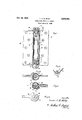
Figure l is a front elevation of the hinge when in opened position having a portion thereof in section.
,Figure 2 is a horizontal'section through the same.
Figure 3 isa similar section when the hinge is in a closed position. l
Figure 4 is a plan view another closed position with a connecting vnut removed, and
Figure 5 is a detail view of a slightly modirled 'form ofthe invention.
The hinge includes a cylinder I containing a cylindrical core 2, therotation of which between two bearings 3 and 4 drives a steel blade 5 constituting a flexible partition the profile of which enables resilient deformations of the edges in the -relative positions of the core to which it is bound and of the cylinder'surrounding the said core. A bearing 4 is made solidary with the cylinder I l by means of a key 6. A plug 1 is aiiixed to the cylinder I by screw-threads and produces by the compression of an elastic washer 8 a tight contact between the ends of the blade 5 and the bearings 3 and 4.
The room between the cylinder I and the core 2, filled with a suitable oil, is divided into two chambers by the blade 5 which forms a partition as shown in Figure 3, a communication between the chambers a and b being obtained by a channel 9 the section of which is adjusted by means of a screw I0.
The plug-shaped bearing 3 also is made solidary with the cylinder I by screw-threads; it includes a stuing-box II affording a tight connection. A' rolled iron sheet casing I2, `rigidly of the hinge when in secured to the cylinder f'I, constitutes one of the hinge plates, and the other plate is made solidary with the core 2 by its upper lug I6 on which a pressure is exerted by the nut I4. A plate I8 rigid with the core is iixedly engaged into a 5 suitably shaped cut of the lug I6. The lower lug I1 is loosely mounted to revolve on the s'creW I5.
In the slightly modified form of the invention as shown in Figure 5, the blade 5 is of a laminated construction and its medial portion together with 10 the proled member I9 are soldered or in any other manner secured to the core 2. This profiled member I9 extends throughout the entire height of the blade 5 and normally tends to retain the opposed sides of the blade inthe positions 15 as shown. When this blade is placed within the -cylinder I the profiled member normally holds the opposed sides of the blade in opened position or a position where the edges thereof will be caused to extend towards the inner wall of the 20 cylinder I. 4In lusing the hinge, the plate I2 is fastened in i the rabbet of the door frame, and the other plate I3 on the edge of the door (or inversely according to the opening direction), so that the ad- 25 justing screw I0 is at the top.
By opening the door the position of the hinge when the door is closed being as shown in Figure 3, the pressure created within the chamber b compels the edges 20 and 2I of the blade 5 to move 30 away from the inside wall of the cylinder I, thus l making a temporary communication between the chambers a andb, so that the oil compressed into chamber b is allowed to enter into chamber a without any resistance action continues until the angular displacement equals angle a as shown in Fig. 3 of the drawing beyond which a new temporary communication is established by means of the edge 2l separating from the wail of the cylinder l; the edge 2n 40 then coming into contact with the cylinder I, and the opening of the door reaching in that way its maximum, that is without any abnormal effort. At this moment, the door being left free to come back, for instance, by the operation of springsor a spring combination independent of this invention, is quickly shut until the edge 2| of the blade v5 again contacts the inside wall of the cylinder I, in the position shown by dotted lines in Fig.'3. There is now no more temporary communication between the two chambers a and b, the compression created lwithin the chamber a brings resilientgdeformations inthe blade 5 with a tendency to tighten the contact between the edges 20 and 2| of the said blade and 55 to the rotation, and this 3J the inside wan of the cylinder. such deforma tions further enable to obtain the required pressure in the brake eiect balancing the said elastic` 'Ihe above described device is also used for the double acting hinges.
Having now described the object of this invention and in which manner same isv to be performed, what I claim is:
1. A hydraulic hinge comprising a cylinder, means for attaching said cylinder to a door,l casing, a spindle movably and eccentrically mounted within said cylinder, a resilient blade secured to said spindle to move therewith and disposed to form variable compression chambers within said cylinder, plug shaped bearings closing the extremities of said cylinder and guiding the spindle and means connected to the spindle for moving the same with the displacement of the door.
2. A hydraulic hinge comprising a cylinder,
means for attaching said cylinder to a door, a spindle movably and eccentrically" mounted within said cylinder, a resilient blade secured to said i spindle to move therewith and disposed to form variable compression chambers within` and throughout the -length \of said cylinder, plug shaped bearings closing said cylinder and guiding the spindle in its movementsfollowing the displacement of thedoor, and means in said spindle establishing -communication between the compression chambers dened by ,said blade.
3. A hydraulic hinge comprising a relatively fixed cylinder, a spindle movably and eccentricalq ly mounted within said cylinder and having a` resilient blade disposed to sub-divide said cylinder into a pair of compression chambers throughout the length of said cylinder, means for closing the cylinder and guiding the spindle, means to cause the movement of the spindle upon the displacement of the door whereby to displace one edge of the spindle blade to and away from the adjacent surface of the cylinder, and means formed in saidspindle and establishing communication between said chambers.v
LUCIEN CHARLES EUGNE MIILY.
Applications Claiming Priority (1)
| Application Number | Priority Date | Filing Date | Title |
|---|---|---|---|
| FR2018564X | 1932-03-30 |
Publications (1)
| Publication Number | Publication Date |
|---|---|
| US2018564A true US2018564A (en) | 1935-10-22 |
Family
ID=9683063
Family Applications (1)
| Application Number | Title | Priority Date | Filing Date |
|---|---|---|---|
| US663629A Expired - Lifetime US2018564A (en) | 1932-03-30 | 1933-03-30 | Hinge with hydraulic brake |
Country Status (1)
| Country | Link |
|---|---|
| US (1) | US2018564A (en) |
Cited By (8)
| Publication number | Priority date | Publication date | Assignee | Title |
|---|---|---|---|---|
| US2811227A (en) * | 1955-01-20 | 1957-10-29 | Houdaille Industries Inc | Flutter damper |
| US3380109A (en) * | 1966-02-02 | 1968-04-30 | William B. Ruiz | Self-closing door hinge |
| DE2644539A1 (en) * | 1976-10-01 | 1978-04-06 | Dictator Tuerschliessergesells | DAMPING DEVICE FOR THE CLOSING MOVEMENT OF SLIDING DOORS OR DGL. |
| US4468836A (en) * | 1980-11-27 | 1984-09-04 | Nifco Inc. | Door dampening mechanism having a non-rotatable vane |
| US4756051A (en) * | 1987-01-23 | 1988-07-12 | Shy Haw Yaw | Door-closer hinge with rotary-movement shock absorber |
| US20140053369A1 (en) * | 2011-05-04 | 2014-02-27 | Olmi S.R.L. | Hinge |
| US20150233164A1 (en) * | 2012-10-04 | 2015-08-20 | In & Tec S.R.L. | Hinge device for doors, shutters and the like |
| US20160145924A1 (en) * | 2013-05-27 | 2016-05-26 | Industria Casearia Silvio Belladelli S.R.L. | Hinges system |
-
1933
- 1933-03-30 US US663629A patent/US2018564A/en not_active Expired - Lifetime
Cited By (11)
| Publication number | Priority date | Publication date | Assignee | Title |
|---|---|---|---|---|
| US2811227A (en) * | 1955-01-20 | 1957-10-29 | Houdaille Industries Inc | Flutter damper |
| US3380109A (en) * | 1966-02-02 | 1968-04-30 | William B. Ruiz | Self-closing door hinge |
| DE2644539A1 (en) * | 1976-10-01 | 1978-04-06 | Dictator Tuerschliessergesells | DAMPING DEVICE FOR THE CLOSING MOVEMENT OF SLIDING DOORS OR DGL. |
| US4468836A (en) * | 1980-11-27 | 1984-09-04 | Nifco Inc. | Door dampening mechanism having a non-rotatable vane |
| US4756051A (en) * | 1987-01-23 | 1988-07-12 | Shy Haw Yaw | Door-closer hinge with rotary-movement shock absorber |
| US20140053369A1 (en) * | 2011-05-04 | 2014-02-27 | Olmi S.R.L. | Hinge |
| US8875345B2 (en) * | 2011-05-04 | 2014-11-04 | Ol.Mi S.R.L. | Hinge |
| US20150233164A1 (en) * | 2012-10-04 | 2015-08-20 | In & Tec S.R.L. | Hinge device for doors, shutters and the like |
| US9605462B2 (en) * | 2012-10-04 | 2017-03-28 | In & Tec S.R.L. | Hinge device for doors, shutters and the like |
| US20160145924A1 (en) * | 2013-05-27 | 2016-05-26 | Industria Casearia Silvio Belladelli S.R.L. | Hinges system |
| US9695622B2 (en) * | 2013-05-27 | 2017-07-04 | Industria Casearia Silvio Belladelli S.R.L. | Hinges system |
Similar Documents
| Publication | Publication Date | Title |
|---|---|---|
| CN107923554B (en) | Vacuum valve | |
| US2018564A (en) | Hinge with hydraulic brake | |
| CN104863460B (en) | Sliding door and window hardware system | |
| US3222709A (en) | Door closing mechanism | |
| US3474485A (en) | Automatic universal door closer | |
| US3091819A (en) | Door control mechanism | |
| US3156002A (en) | Hold-open mechanism for door closer | |
| US2434524A (en) | Door checking hinge | |
| US987467A (en) | Double-acting spring-hinge. | |
| US3044103A (en) | Door closer | |
| US2116185A (en) | Door closer and check | |
| US1731561A (en) | Automatic door-closing device | |
| US2251865A (en) | Hinge | |
| CN203835118U (en) | Door closer | |
| US2909801A (en) | Door closer | |
| US1613138A (en) | Gate valve | |
| US2915778A (en) | Door holding device | |
| CN104791517A (en) | Connecting rod mutual sealing water distribution structure | |
| CN210484654U (en) | Threaded connection gate valve copper valve body | |
| JPH08200265A (en) | Capacity-volume ratio control valve aggregate | |
| CN205445251U (en) | Door closer operates steadily | |
| US2817978A (en) | Sash operator | |
| US1999274A (en) | Door closer and check | |
| US3673736A (en) | Device for operating sliding doors | |
| US2560139A (en) | Window frame and sash assembly |