EP2784353A1 - Reel part for fishing reel - Google Patents
Reel part for fishing reel Download PDFInfo
- Publication number
- EP2784353A1 EP2784353A1 EP20140156732 EP14156732A EP2784353A1 EP 2784353 A1 EP2784353 A1 EP 2784353A1 EP 20140156732 EP20140156732 EP 20140156732 EP 14156732 A EP14156732 A EP 14156732A EP 2784353 A1 EP2784353 A1 EP 2784353A1
- Authority
- EP
- European Patent Office
- Prior art keywords
- reel
- inner member
- outer member
- gear teeth
- spool
- Prior art date
- Legal status (The legal status is an assumption and is not a legal conclusion. Google has not performed a legal analysis and makes no representation as to the accuracy of the status listed.)
- Granted
Links
Images






Classifications
-
- A—HUMAN NECESSITIES
- A01—AGRICULTURE; FORESTRY; ANIMAL HUSBANDRY; HUNTING; TRAPPING; FISHING
- A01K—ANIMAL HUSBANDRY; AVICULTURE; APICULTURE; PISCICULTURE; FISHING; REARING OR BREEDING ANIMALS, NOT OTHERWISE PROVIDED FOR; NEW BREEDS OF ANIMALS
- A01K89/00—Reels
- A01K89/006—Hand crank features
-
- A—HUMAN NECESSITIES
- A01—AGRICULTURE; FORESTRY; ANIMAL HUSBANDRY; HUNTING; TRAPPING; FISHING
- A01K—ANIMAL HUSBANDRY; AVICULTURE; APICULTURE; PISCICULTURE; FISHING; REARING OR BREEDING ANIMALS, NOT OTHERWISE PROVIDED FOR; NEW BREEDS OF ANIMALS
- A01K89/00—Reels
-
- A—HUMAN NECESSITIES
- A01—AGRICULTURE; FORESTRY; ANIMAL HUSBANDRY; HUNTING; TRAPPING; FISHING
- A01K—ANIMAL HUSBANDRY; AVICULTURE; APICULTURE; PISCICULTURE; FISHING; REARING OR BREEDING ANIMALS, NOT OTHERWISE PROVIDED FOR; NEW BREEDS OF ANIMALS
- A01K89/00—Reels
- A01K89/01—Reels with pick-up, i.e. with the guiding member rotating and the spool not rotating during normal retrieval of the line
-
- A—HUMAN NECESSITIES
- A01—AGRICULTURE; FORESTRY; ANIMAL HUSBANDRY; HUNTING; TRAPPING; FISHING
- A01K—ANIMAL HUSBANDRY; AVICULTURE; APICULTURE; PISCICULTURE; FISHING; REARING OR BREEDING ANIMALS, NOT OTHERWISE PROVIDED FOR; NEW BREEDS OF ANIMALS
- A01K89/00—Reels
- A01K89/015—Reels with a rotary drum, i.e. with a rotating spool
-
- F—MECHANICAL ENGINEERING; LIGHTING; HEATING; WEAPONS; BLASTING
- F16—ENGINEERING ELEMENTS AND UNITS; GENERAL MEASURES FOR PRODUCING AND MAINTAINING EFFECTIVE FUNCTIONING OF MACHINES OR INSTALLATIONS; THERMAL INSULATION IN GENERAL
- F16H—GEARING
- F16H55/00—Elements with teeth or friction surfaces for conveying motion; Worms, pulleys or sheaves for gearing mechanisms
- F16H55/02—Toothed members; Worms
- F16H55/06—Use of materials; Use of treatments of toothed members or worms to affect their intrinsic material properties
-
- F—MECHANICAL ENGINEERING; LIGHTING; HEATING; WEAPONS; BLASTING
- F16—ENGINEERING ELEMENTS AND UNITS; GENERAL MEASURES FOR PRODUCING AND MAINTAINING EFFECTIVE FUNCTIONING OF MACHINES OR INSTALLATIONS; THERMAL INSULATION IN GENERAL
- F16H—GEARING
- F16H55/00—Elements with teeth or friction surfaces for conveying motion; Worms, pulleys or sheaves for gearing mechanisms
- F16H55/02—Toothed members; Worms
- F16H55/17—Toothed wheels
Definitions
- the present invention generally relates to a reel part. More specifically, the present invention relates to a reel part for a fishing reel.
- a drive gear that transmits the rotation of the handle to the spool must have strong gear teeth in order to pull in fish with a strong pull.
- a member with an overall high degree of strength is used, making the drive gear lightweight is difficult.
- a drive gear as a reel part for a spinning reel one that comprises an aluminum alloy disc part and a zinc alloy teeth part on the outer periphery of the disc part is conventionally known.
- Japanese Laid-Open Patent Publication No. 1998-150889 discloses such a drive gear.
- the teeth part is integrally molded on the outer periphery of the disc by outsert molding.
- surface treatment layer such as anodic oxide layer, etc.
- surface treatment layer is formed in order to improve corrosion resistance.
- a zinc alloy is integrally molded to a disc part on which such a surface treatment layer is formed, there is the possibility that the surface treatment layer will be damaged and that the performance of the surface treatment layer in the reel part will degrade.
- the gear teeth are formed using outsert molding, there is the risk that the accuracy of the gear teeth will decrease. If the accuracy of the gear teeth decreases, the engagement of the drive gear and gears that engage with the drive gear becomes poor, complicating the smooth rotation of the rotating parts that rotate with the rotation of the drive gear, such as a spool or a rotor.
- One object of the present invention is to achieve a light weight reel part while maintaining the accuracy, strength, and surface treatment layer performance of the reel part.
- the reel part for fishing reels comprises an inner member and an outer member.
- the inner member comprises a surface treatment layer.
- the outer member comprises a processed part.
- the outer member is fixed on the outer peripheral side of the inner member, and is processed after being fixed to the inner member to form the processed part.
- the processed part can comprise gear teeth.
- the strength of the gear teeth can be maintained.
- the gear teeth can also be formed by machining. In this case, the gear teeth can be formed with a high degree of accuracy.
- the gear teeth can also be formed by casting.
- the face gear teeth which increases the cost when formed by machining, can be formed while suppressing an increase in cost.
- the inner member can he made from a first metal having a corrosion- resistant layer as the surface treatment layer, and the outer member can have gear teeth and be made from a second metal that has a specific gravity that is larger and a rigidity that is higher than the first metal. In this case, lightweight gears can he achieved while the strength and corrosion resistance of the gear teeth are maintained.
- the inner member can fit the outer member and can be fixed to the outer member by press fitting. In this case, the inner member and the outer member can be solidly fixed by press fitting.
- the inner member can he fixed to the outer member by plastic deformation towards the outer member. In this case, for example, the inner member and the outer member can be solidly fixed by plastic deformation, such as press fixing, etc.
- the inner member can be fixed to the outer member by bonding.
- the inner member and the outer member can be easily fixed. Additionally, by combining the fixing and bonding by press fitting or plastic deformation mentioned above, the inner member and the outer member can be more solidly fixed.
- the inner member can comprise a male threaded part
- the outer member can comprise a female threaded part that screws onto the male threaded part.
- the inner member and the outer member can be easily fixed by a threaded engagement.
- the inner member and the outer member can each comprise a detent part to engage with each other and to prevent the rotation.
- the brakes will be applied to the rotation of the inner member and the outer member, even if the inner member and the outer member are fixed by press fitting, elastic deformation, bonding, etc., the inner member and outer member can be reliably rotated integrally.
- the inner member can be mounted on a drive axle that rotates in conjunction with a handle of the fishing reel, and the gear teeth of the outer member can engage with a pinion gear that rotates around a spool axis of the fishing reel.
- a lightweight drive gear can be achieved while maintaining the accuracy, the strength, and the surface treatment layer performance of the drive gear of a dual-bearing reel, a spinning reel, or a single-bearing reel.
- the fishing reel can be a dual-bearing reel that has a spool that rotates around an axis of a spool axle that is parallel with an axis of a drive axle.
- the inner member is rotatably mounted on the drive axle in conjunction with the drive axle of the dual-hearing reel.
- a lightweight drive gear can be achieved while maintaining the accuracy, strength, and surface treatment layer performance of the drive gear.
- the fishing reel can be a spinning reel having a spool that reciprocates forward and backward in an axial direction of a spool axle that is transverse to an axis of the drive axle, and the inner member can be integrally and rotatably mounted on the drive axle of the spinning reel.
- a lightweight drive gear can be achieved while maintaining the accuracy, strength, and surface treatment layer performance of the drive gear.
- a lightweight reel part can be achieved while maintaining the accuracy, strength, and the surface treatment layer performance of the reel part.
- a dual-bearing reel employing the first embodiment of the present invention is, for example, a medium-sized round reel used for jigging.
- the round reel comprises a reel body 1, a handle 2 for rotating a spool that is disposed on the side of the reel body 1, and a star drag 3 that is disposed on the reel body 1 side of the handle 2.
- a spool 15 is rotatably mounted on the reel body 1.
- the reel body 1 can be mounted to the fishing rod R via a fishing rod mounting leg 4.
- the reel body 1, as shown in FIG. 2 comprises a frame 5, a first side cover 13, a second side cover 14, and a mechanism mounting plate 16.
- the frame 5 comprises a first side plate 10 and a second side plate 11 that are disposed with a predefined gap in between them, a rear part coupling member 12a that couples the first side plate 10 and the second side plate 11 in the rear part, a lower part coupling member 12b that couples them in the lower part, and a front part coupling member 12c that couples them in the front part.
- the first side cover 13 is integrally formed with the first side plate so as to cover the first side plate 10 laterally.
- the second side cover 14 is integrally formed with the second side plate 11 so as to cover the second side plate 11 laterally.
- the mechanism mounting plate 16 is disposed on the second side plate 11, and a space to house the various mechanisms mentioned below is formed between the mechanism mounting plate 16 and the second side cover 14.
- the frame 5 is obtained through die cast molding, and the second side cover 14 is obtained through press molding a thin metal plate.
- the first side plate 10, the second side plate 11, and the first side cover 13 each form a near circle when seen from the side, and the outer peripheral surface is machined using, for example, a lathe, etc.
- the second side cover 14 and the mechanism mounting plate 16, as shown in FIGS. 1 to 3 each have a shape in which a part of the near circle, as seen from the side, protrudes in the radial direction.
- the second side cover 14 bulges outwardly in the axial direction with the mounting part of the drive axle 30 (mentioned below) as the center.
- the rear part coupling member 12a, the lower part coupling member 12b, and the front part coupling member 12c are plate-like members that are integrally formed with the first side plate 10 and the second side plate 11 in a shape that follows the outer periphery of the first side plate 10 and the second side plate 11.
- the rear part coupling member 12a, the lower part coupling member 12b, and the front part coupling member 12c couple the first side plate 10 and the second side plate 11 in three locations.
- a fishing rod mounting leg 4 is fixed to the lower part coupling member 12b.
- the fishing rod mounting leg 4 is disposed in the longitudinal direction along the center position between the first side plate 10 and the second side plate 11 of the frame 5. This center position is also the center position of the spool part of the spool 15.
- a synthetic resin thumb rest 17 for retaining the reel along with the fishing rod R is mounted on the rear part coupling member 12a.
- the thumb rest 17 is formed so as to come into contact with the upper part and the rear part of the rear part coupling member 12a, and the rear part protrudes in the radial direction outwardly from the first side plate 10 and the second side plate 11, i.e., rearward.
- the upper surface rear part of the thumb rest 17 is tilted while curving convexly downward. Additionally, the protrusion amount rearward of the left end and the right end of the upper surface rear part of the thumb rest 17 gradually declines toward the left side.
- the fishing rod R can be reliably retained along with the reel body 1 during vertical jigging, etc.
- the handle 2 as shown in FIGS. 2 and 3 , comprises a crank arm 6 that is non-rotatably mounted on the tip of the drive axle 30 and a handle grip 7 that is rotatably mounted to one end of the crank arm 6 around the grip shaft axis that intersects perpendicularly with one end part of the crank arm 6.
- the rotating plane of the proximal end part of the handle grip 7 is closer to the reel body 1 side than the rotating plane of the fixed part from the crank arm 6 to the drive axle 30.
- the distance between the handle grip 7 and the fishing rod R becomes closer than in conventional configurations; the torque around the axis of the fishing rod R when the handle grip 7 is rotated and when the fishing line is wound up decreases; and the decrease in the handle winding efficiency can be suppressed.
- the spool 15, as shown in FIG. 2 is rotatably disposed between the first side plate 10 and the second side plate 11.
- the spool 15 comprises a bobbin trunk 15a to which the fishing line is wound, and a pair of flanges 15b that are disposed on both sides of the bobbin trunk 15a.
- a spool axle 25 is fixed to the center of the bobbin trunk 15a.
- the spool axle 25 is rotatably supported independently by the reel body 13 via an axle bearing 26a, by the mechanism mounting plate 16 via an axle bearing 26b, and by the second side cover I 4 via an axle bearing 27b.
- a casting control mechanism 36 is disposed on both ends of the spool axle 25.
- a rotation transmission mechanism 20 fix transmitting the torque from the handle 2 to the spool 15, a clutch mechanism 21 that is installed in the rotation transmission mechanism 20, and a clutch operating mechanism 22 for conducting the on/off operation of the clutch mechanism 21.
- the rotation transmission mechanism 20 comprises a rotation control mechanism for regulating the torque when the torque is reversely transmitted from the spool 15 to the side with the handle 2.
- a centrifugal brake mechanism 24 for controlling the spool 15 that freely rotates in the line delivering direction is disposed in the center part of the second side plate 11.
- a sounding mechanism that makes a sound during the rotation of the spool 15 and a lock mechanism that completely locks the spool 15 to facilitate the breakage of the line when snagging occurs, etc.
- the rotation transmission mechanism 20 as shown in FIGS. 2 and 3 , comprises a drive axle 30 on one end where the handle 2 is fixed, a drive gear 31 that is coupled to the other end of the drive axle 30 via the rotation control mechanism 23, and a pinion gear 32 that engages with the drive gear 31.
- the drive gear 31 is one example of a reel part according to the first embodiment of the present invention.
- the drive axle 30 is disposed parallel to the spool axle 25.
- One end of the drive axle 30 is rotatably supported by the mechanism mounting plate 16 via an axle bearing 35a, and the center part is rotatably supported by a first boss part 14a of the second side cover 14 via an axle bearing 35b.
- the rotation of the drive axle 30 in the line delivering direction is prohibited by one-way clutches 55 and 60 mentioned below.
- the drive gear 31 is rotatably mounted to one end side of the drive axle 30 and is integrally rotatable with the drive axle 30 via the rotation control mechanism 23.
- the drive gear 31, as shown in FIGS. 3 to 5 comprises a disc-shaped inner member 31 a that has a surface treatment layer 31 c (refer to FIG. 5 ) and an annular ring-shaped outer member 31 b that is fixed to the outer peripheral surface of the inner member 31 a and that has multiple gear teeth 31 d on the outer peripheral surface.
- the multiple gear teeth 31 d are disposed with a gap in the circumferential direction.
- the inner member 31a is, for example, a first metallic member with a relatively small specific gravity, such as aluminum alloys and magnesium alloys.
- the inner member 31a further comprises a through-hole 31e that is rotatably mounted to the drive axle 30 and a circular outer peripheral part 31f that is fixed by press fitting to the outer member 31 b.
- the surface treatment layer 31 c is a corrosion- resistant layer such as an anodic oxide layer, etc.
- the surface treatment layer 31c is formed on the entire surface of the outer surface, including the through-hole 31 e of the inner member 31 a, the outer peripheral part 31f, an engaging recess 34a of the detent part 34 mentioned below, a surface that intersects perpendicularly with the axis of the drive axle 30, etc.
- the inner member 31a is formed so that the outer peripheral side to which the outer member 31h is fixed is formed to be thicker than the inner peripheral side.
- the outer member 31 b is a second metallic member with a larger specific gravity and a higher rigidity than the inner member 31 a, for example a zinc alloy or a stainless steel alloy.
- the outer member 31 b comprises a circular inner peripheral part 31 g that fits the outer peripheral part 31f of the inner member 31a.
- the gear teeth 31d that are formed on the outer peripheral surface are one example of a processed part, and they are formed through machining (gear cutting) after the outer member 31 b is fixed to the inner member 31 a.
- the gear teeth 31 d the number of teeth is in the range of 100 to 120 and is a helical gear with a helical angle of less than 20 degrees the pitch circle diameter is around 42 mm, and the module is 0.35.
- the drive gear 31 further comprises a detent part 34 that is installed between the inner member 31a and the outer member 31 b, that engages with the inner member 31 a and the outer member 31b and that prevents the rotation of the inner member 31a and the outer member 31 b.
- the detent part 34 comprises a plurality of engaging recesses 34a (for example 3) that are formed as a semi-circle on the outer peripheral part 31f of the inner member 31a and a plurality of engaging protrusions 34b (for example 3) that are formed in a semi-circle on the inner peripheral part 31 g of the outer member 31 h so as to engage with the engaging recesses 34a.
- an engaging protrusion 34b was thinly formed on the outer member 31 b in the radial direction, a decrease in the strength of the outer member 31 b can be suppressed.
- the plurality of engaging recesses 34a and the plurality of engaging protrusions 34b are disposed at equal intervals in the peripheral direction. With this, even if the drive gear 31 rotates, the balance of the rotation will not easily become unbalanced, so a smooth rotation of the drive gear 31 will not be inhibited. Meanwhile, the disposition of the engaging recesses and the engaging protrusions can be reversed, the engaging recesses can be installed on the outer member, and the engaging protrusions can be installed on the inner member. With the engagement of the recesses and protrusions of these engaging recesses 34a and the engaging protrusions 34b, the detents can be applied to stop the rotation of the outer member 31 b with respect to the inner member 31 a
- the drive gear 31 is manufactured from a ring member 53 in which configurations besides the gear teeth 31 d are formed and becomes the outer member 31 b and the inner member 31 a that have all of the configurations, including the surface treatment layer 31 c.
- the pinion gear 32 configures the rotation transmission mechanism 20 and, at the same time, functions as the clutch mechanism 21.
- the pinion gear 32 comprises a cross-shaped engaging groove 32a that is formed on one end, a constricted part 32b that is formed at the midpoint, multiple gear teeth 32c that are formed adjacent to the constricted part 32b, and an axle bearing support part 32d that is formed on the other end.
- the gear teeth 32c of the pinion gear 32 engage with the gear teeth 31 d of the drive gear 31.
- the number of teeth of the gear teeth 32c of the pinion gear 32 is, for example, "18". In FIG. 3 , the number of teeth is not accurately depicted.
- both ends of the pinion gear 32 are supported by the reel body 1. Specifically, one end of the pinion gear 32 on which the engaging groove 32a is formed and the other end on which the axle bearing support part 32d is formed are each separately supported rotatably by the mechanism mounting plate 16 via the axle bearing 27a and by the second boss part 14b of the second side cover 14 via the axle hearing 27b. Additionally, the pinion gear 32 can move between the clutch on position diagrammed in the lower side of the spool shaft axis C in FIG. 2 and the clutch off position diagrammed on the upper side of the spool shaft axis C in the spool axial direction.
- the clutch mechanism 21 comprises a tube-shaped pinion gear 32 that is slidably mounted on the outer peripheral part of the spool axle 25, an engaging groove 32a that is disposed on one part of the pinion gear 32, and a clutch pin 33 that is disposed on the spool axle 25. If the pinion gear 32 is slid along the spool axle 25 and the engaging groove 32a is engaged with the clutch pin 33, the torque is transmitted between the spool axle 25 and the pinion gear 32. This state is the coupled state (the clutch on state). If the engagement of the engaging groove 32 and the clutch pin 33 is disengaged, the torque is not transmitted between the spool axle 25 and the pinion gear 32. This state is the cutoff state (the clutch off state). In the clutch off state, the spool 15 rotates freely. The pinion gear 32 is biased in the direction in which the engaging groove 32a and the clutch pin 33 engage, that is, in the clutch on state, by the clutch operating mechanism 22.
- the rotation control mechanism 23 comprises a roller-type, one-way clutch 55 that rotates the drive axle 30 only in the line winding direction (and prohibits the rotation in the line delivering direction), a drag mechanism 57, and a pawl-type, one-way clutch 60.
- the drag mechanism 57 is a mechanism that applies a predefined braking force to the rotation in the line delivering direction of the spool 15.
- the drag mechanism 57 can adjust the drag force with the star drag 3.
- the drag mechanism 57 as shown in FIG. 3 , comprises a plurality of drag washers 57a that are mounted on the drive axle 30. A part of the drag washers 57a is integrally and rotatably mounted on the drive axle 30, and the rest are rotatably mounted on the drive axle 30.
- the pawl-type, one-way clutch 60 rotates the drive axle 30 only in the line winding direction.
- the pawl-type, one-way clutch 60 as shown in FIGS. 2 and 3 , comprises a ratchet wheel 61 that is integrally and rotatably mounted on the drive axle 30 and a ratchet pawl 62 that can engage with the ratchet wheel 61.
- the ratchet pawl 62 (refer to FIG. 3 ) is biased to the ratchet wheel 61 side.
- the clutch operating mechanism 22 comprises a clutch operating lever 40 to switch the clutch mechanism 21 into the clutch on and clutch off states.
- the clutch operating lever 40 is slidably mounted on the outer side surface of the second side cover 14.
- the clutch operating mechanism 22 moves the pinion gear 32 into the clutch on position and the clutch off position in conjunction with the operation of the clutch operating lever 40.
- the outer member 31 b is fixed to the inner member 31 a comprising a surface treatment layer 31 c, after which the gear teeth 31 d of the outer member 31 h are machined.
- the surface treatment layer 31 c will no longer be easily affected; therefore, the performance of the surface treatment layer 31c can be maintained, and the accuracy of the gear teeth 31 d can remain high.
- the strength can be maintained, and a lightweight drive gear 31 can be achieved.
- the drive gear according to the first embodiment of the present invention was explained using a dual-bearing reel as an example; however, in the second embodiment, a drive gear of a spinning reel will be explained.
- a spinning reel that employs the second embodiment of the present invention is a medium-sized spinning reel.
- the spinning reel comprises a handle 101, a reel body 102 that rotatably supports the handle 101, a rotor 103, and a spool 104.
- the rotor 103 is rotatably supported by the front part of the reel body 102.
- the spool 104 is for winding the fishing line to the outer peripheral surface and is disposed to be movable to the front and back between first rotor arm 131 and the second rotor am 132 of the rotor 103.
- the handle 101 can be mounted to either the left side or the right side of the reel body 102.
- the handle 101 as shown in FIG. 7 and FIG. 8 , comprises a handle axle 101a, a handle arm 101b b that extends from the handle axle 101 a in the radial direction, and a handle grip 101 c that is rotatably installed at the tip of the handle arm 101 b.
- the reel body 102 comprises a reel body 102a that has a housing space inside whose side part opens and a cover member 102b ( FIG. 8 ) that is detachably mounted to the reel body 102a to plug the housing space of the reel body 102a. Additionally, the reel body 102 comprises a main body guard 126 that covers the reel body 102a and the rear part of the cover member 102b.
- the reel body 102a is, for example, made of a light alloy, such as a magnesium alloy and an aluminum alloy; a T-shaped fishing rod mounting leg 102c that extends forward and backward is integrally formed on the upper part.
- a mounting seat 102d to which the fishing rod R is mounted forwardly descending in the longitudinal direction is disposed on the upper part of the fishing rod mounting leg 102c.
- the transverse section of the mounting seat 102d is depressed curving in a circular arc shape.
- a rotation transmission mechanism 105 and an oscillating mechanism 106 are installed in the housing space of the reel body 102a, as shown in FIG. 7 .
- the rotation transmission mechanism 105 transmits the rotation of the handle 101 to the rotor 103 as well as the spool 104.
- the rotation transmission mechanism 105 rotates the rotor 103 in conjunction with the rotation of the handle 101 and moves the spool 104 forward and backward.
- the rotation transmission mechanism 105 as shown in FIGS. 8 and 9 , comprises a drive axle 110 with which the handle axle 101 a of the handle 101 is integrally and rotatably coupled, a drive gear 111 consisting of a face gear that rotates along with the drive axle 110, and a pinion gear 112 that engages with this drive gear 111.
- the drive gear 111 is one example of a reel part according to the second embodiment. As shown in FIG.
- the drive gear 111 is formed integrally with or separately from (integrally in this embodiment) the drive axle 110.
- the drive axle 110 is integrally and rotatably coupled with the handle axle 101 a by a threaded coupling or a noncircular engagement (a threaded coupling in this embodiment).
- the drive axle 110 is rotatably mounted to the reel body 102 by an axle bearing 127a that is mounted on a cover member 102b and an axle bearing 127b that is mounted on the reel body 102a.
- a left female threaded part 110a and a right female threaded part 110b that screw onto the handle axle 101 a are formed on the inner peripheral surface of both ends of the drive axle.
- the left female threaded part 110a on the near side of the drive gear 111 is a left screw
- the right female threaded part 110b that is on the far side of the drive gear 111 is a right screw. Therefore, there are two kinds of handle axes 101a that are prepared, one for the right screw and another for the left screw.
- the drive gear 111 as shown in FIGS. 8 , 9 and 10 , comprises an inner member 111a that is integrally formed with the drive axle 110 and that has a surface treatment layer 111c (refer to FIG. 10 ); and an annular ring-shaped outer member 111 b that is fixed on the outer peripheral side of the inner member 111a and that has multiple face gear teeth 111d on one side surface of the outer peripheral side.
- the multiple face gear teeth 111d are disposed with a gap in the circumferential direction.
- the inner member 111 a along with the drive axle 110, is a first metallic member with a relatively small specific gravity, such as an aluminum alloy and a magnesium alloy.
- the inner member 111a is formed by casting the first metal, after which a surface treatment layer 111c is formed.
- the inner member 111 a comprises a circular outer peripheral part 111f that is fixed to the outer member 111b by press fitting.
- the surface treatment layer 111c is a corrosion-resistant layer such as an anodic oxide layer, etc.
- the surface treatment layer 111 c is formed on the entire surface of the outer surface, including an outer peripheral part 111f of the inner member 111a, a semi-circular first engaging recess 135a with which a detent part 134 mentioned below engages, and a surface that intersects perpendicularly with the axis of the drive axle 110, etc.
- the outer member 111 b is a second metallic member with a larger specific gravity and a higher rigidity than the inner member 111 a, for example a zinc alloy or a stainless steel alloy.
- the outer member 111b further comprises a circular inner peripheral part 111g that fits the outer peripheral part 111f of the inner member 111 a.
- the face gear teeth 111d formed on the outer peripheral surface are one example of a processed part, and they are formed through casting after the outer member 111 b is fixed to the inner member 111 a.
- the number of teeth of the face gear teeth 111d is, for example, between 50 and 70; the outer diameter is, for example, around 26 mm; and the inner diameter is, for example, around 21 mm.
- the drive gear 111 further comprises a detent part 134 that is installed between the inner member 111 a and the outer member 111 b and that engages with the inner member 111 a and the outer member 111 b and prevents the rotation of the inner member 111 a and the outer member 111 b.
- the detent part 134 comprises a plurality of rotation brake pins 134a (for example, 4) that engage with the inner member 111a and the outer member 111 b. Therefore, in the second embodiment, the detent part 134 is installed separately from the inner member 111a and the outer member 111 b.
- the rotation brake pins 134a fit a through-hole 135 that is formed from a plurality of first engaging recesses 135a (for example 4) that are formed as a semi-circle on the outer peripheral part 111f of the inner member 111a a and a plurality of second engaging recesses 135b (for example 4) that are formed in a semi-circle on the inner member 111g of the outer member 111 b.
- the rotation brake pin 134a is stopped in the through-hole 135 by caulk fixing that presses both ends and plastically deforms them.
- the plurality of through-holes 135 is disposed in the circumferential direction at equal intervals.
- the pinion gear 112 comprises a tube-shaped gear main body 112a and gear part 112b that comprises a helical gear 112c and that is formed on the rear part outer peripheral surface of the gear main body 112a.
- the gear main body 112a is rotatably mounted on the red body 102a around an axis that crisscrosses the handle axle 101 a (around the spool axle 115).
- the gear main body 112a as shown in FIG.
- the rotor 7 is rotatably supported by a reel body 102a by a front axle bearing 114a and a rear axle bearing 114b in the vicinity of the gear part 112b.
- the spool axle 115 can penetrate the center of the gear main body 112a.
- a nut 113 for fixing the rotor 103 screws onto the front end outer peripheral surface for the gear main body 112a.
- the rotor 103 is integrally and rotatably coupled to the front part outer peripheral surface of the gear main body 112a.
- the oscillating mechanism 106 is a mechanism for moving a spool axle 115 that is coupled to the center part of the spool 104 via a drag mechanism 160 forward and backward to move the spool 104 in the same direction.
- the oscillating mechanism 106 comprises a traverse camshaft 121 that is disposed in parallel under the spool axle 115, a slider 122 that is guided to the reel body 102a in the longitudinal direction along the traverse camshaft 121, and an intermediate gear 123 that is fixed to the tip of the traverse camshaft 121.
- the slider 122 is fixed non-rotatably to the rear end of the spool axle 115.
- An intermediate gear 123 engages with the pinion gear 112.
- the rotor 103 is a light alloy such as a magnesium alloy and an aluminum alloy, is non-rotatably coupled to the pinion gear 112, and is rotatable with respect to the reel body 102.
- the rotor 103 comprises a tube section 130 that is integrally and rotatably coupled with the pinion gear 112, and a first rotor arm 131 and a second rotor arm 132 that are connected to a position facing the rear part of the tube section 130 and that extend forward with a space between them and the tube section 130.
- the tube section 130 comprises a disc-shaped wall part 130d on the front part inner peripheral side, and an annular boss section 130e that is integrally and rotatably coupled with the pinion gear 112 formed in the center part of the wall part 130d.
- the front part of the pinion gear 112 penetrates the inner peripheral part of this boss section 130e, and the boss section 130e is integrally and rotatably locked to the front part of the pinion gear 112.
- the rotor 103 is fixed to the pinion gear 112.
- a bail arm 144 that guides the fishing line to the spool 104 in the line releasing direction and the line winding direction is slidably mounted on the outer peripheral side of the tip of the first rotor arm 131.
- a reverse rotation prevention mechanism 150 is disposed inside of the tube section 130 of the rotor 103 for prohibiting / releasing the reverse rotation of the rotor 103.
- the reverse rotation prevention mechanism 150 has a roller-type, one-way clutch 151 whose inner ring idles and a switching lever 152 that switches the one-way clutch 151 between the operating state (the reverse rotation prohibited state) and the non-operating state (the reverse rotation permitted state).
- the switching lever 152 is slidably mounted on the reel body 102a.
- a cam which is not diagrammed, is installed on the tip of the switching lever 152; if the switching lever 152 is oscillated, the one-way clutch 151 switches between the operating state and the non-operating state due to the cam.
- the spool 104 is disposed between the first rotor arm 131 and the second rotor arm 132 of the rotor 103 and is mounted to the tip of the spool axle 115 via a drag mechanism 160.
- the spool 104 comprises a bobbin trunk 104a, the outer periphery to which is wound the fishing line, a tube-shaped skirt section 104c that is integrally formed with the bobbin trunk 104a at the rear of the bobbin trunk 104a, and a large-diameter flange part 104b that is installed on the front end of the bobbin trunk 104a.
- the drag mechanism 160 brakes the rotation of the spool 104 and comprises a drag adjustment knob 161 that is screwed onto the tip of the spool 115 and a braking section 162 that is pressed by the drag adjustment knob 161 and that brakes the spool 104.
- the face gear teeth 111 d of the outer member 111 b are cast after fixing the outer member 111h to the inner member 111 a, which has a surface treatment layer 111 c.
- the surface treatment layer 111c will no longer be easily affected; therefore, the performance of the surface treatment layer 111c can be maintained, and the accuracy of the gear teeth 111d can remain high.
- the strength can be maintained, and a lightweight drive gear 111 can be achieved.
- the gear teeth 31 d (or face gear teeth 111 d) of the outer member 31 b (or 111 b) are processed after fixing the outer member 31 b (or 111 b) to the inner member 31 a (or 111 a) that has a surface treatment layer 31 c (or 111c).
- the surface treatment layer 31c (or 111c) will no longer be affected; therefore, the performance of the surface treatment layer 31c (or 111c) can be maintained, and the accuracy of the gear teeth 31 d (or face gear teeth 111 d) can remain high.
- the strength can be maintained, and a light weight can be achieved.
Landscapes
- Life Sciences & Earth Sciences (AREA)
- Environmental Sciences (AREA)
- Animal Husbandry (AREA)
- Biodiversity & Conservation Biology (AREA)
Abstract
Description
- The present invention generally relates to a reel part. More specifically, the present invention relates to a reel part for a fishing reel.
- Reel parts that require strength and need to be lightweight are used for fishing reels. For example, a drive gear that transmits the rotation of the handle to the spool must have strong gear teeth in order to pull in fish with a strong pull. However, if a member with an overall high degree of strength is used, making the drive gear lightweight is difficult. Thus, in order to maintain the strength of the drive gear and to make the drive gear lightweight, in a drive gear as a reel part for a spinning reel, one that comprises an aluminum alloy disc part and a zinc alloy teeth part on the outer periphery of the disc part is conventionally known. For example, Japanese Laid-Open Patent Publication No.
1998-150889 - Generally, with light alloys of aluminum, etc., surface treatment layer such as anodic oxide layer, etc., is formed in order to improve corrosion resistance. If a zinc alloy is integrally molded to a disc part on which such a surface treatment layer is formed, there is the possibility that the surface treatment layer will be damaged and that the performance of the surface treatment layer in the reel part will degrade. Additionally, if the gear teeth are formed using outsert molding, there is the risk that the accuracy of the gear teeth will decrease. If the accuracy of the gear teeth decreases, the engagement of the drive gear and gears that engage with the drive gear becomes poor, complicating the smooth rotation of the rotating parts that rotate with the rotation of the drive gear, such as a spool or a rotor.
- One object of the present invention is to achieve a light weight reel part while maintaining the accuracy, strength, and surface treatment layer performance of the reel part.
- The reel part for fishing reels according to the present invention comprises an inner member and an outer member. The inner member comprises a surface treatment layer. The outer member comprises a processed part. The outer member is fixed on the outer peripheral side of the inner member, and is processed after being fixed to the inner member to form the processed part.
- In this reel part, after an outer member is fixed to an inner member that has a surface treatment layer, the processed part of the outer member is processed. With this, the surface treatment layer will no longer be affected; therefore, the performance of the surface treatment layer can be maintained, and the accuracy for the processed part can remain high. Additionally, by using a material with a small specific gravity for the inner member and by using that with high rigidity for the outer member, the strength can be maintained, and a lightweight can be achieved.
- The processed part can comprise gear teeth. In this case, the strength of the gear teeth can be maintained.
- The gear teeth can also be formed by machining. In this case, the gear teeth can be formed with a high degree of accuracy.
- The gear teeth can also be formed by casting. In this case, the face gear teeth, which increases the cost when formed by machining, can be formed while suppressing an increase in cost.
- The inner member can he made from a first metal having a corrosion- resistant layer as the surface treatment layer, and the outer member can have gear teeth and be made from a second metal that has a specific gravity that is larger and a rigidity that is higher than the first metal. In this case, lightweight gears can he achieved while the strength and corrosion resistance of the gear teeth are maintained. The inner member can fit the outer member and can be fixed to the outer member by press fitting. In this case, the inner member and the outer member can be solidly fixed by press fitting. The inner member can he fixed to the outer member by plastic deformation towards the outer member. In this case, for example, the inner member and the outer member can be solidly fixed by plastic deformation, such as press fixing, etc.
- The inner member can be fixed to the outer member by bonding. In this case, the inner member and the outer member can be easily fixed. Additionally, by combining the fixing and bonding by press fitting or plastic deformation mentioned above, the inner member and the outer member can be more solidly fixed.
- The inner member can comprise a male threaded part, and the outer member can comprise a female threaded part that screws onto the male threaded part. In this case, the inner member and the outer member can be easily fixed by a threaded engagement.
- The inner member and the outer member can each comprise a detent part to engage with each other and to prevent the rotation. In this case, since the brakes will be applied to the rotation of the inner member and the outer member, even if the inner member and the outer member are fixed by press fitting, elastic deformation, bonding, etc., the inner member and outer member can be reliably rotated integrally.
- The inner member can be mounted on a drive axle that rotates in conjunction with a handle of the fishing reel, and the gear teeth of the outer member can engage with a pinion gear that rotates around a spool axis of the fishing reel. In this case, a lightweight drive gear can be achieved while maintaining the accuracy, the strength, and the surface treatment layer performance of the drive gear of a dual-bearing reel, a spinning reel, or a single-bearing reel.
- The fishing reel can be a dual-bearing reel that has a spool that rotates around an axis of a spool axle that is parallel with an axis of a drive axle. The inner member is rotatably mounted on the drive axle in conjunction with the drive axle of the dual-hearing reel. In this case, in the dual-bearing reel, a lightweight drive gear can be achieved while maintaining the accuracy, strength, and surface treatment layer performance of the drive gear.
- The fishing reel can be a spinning reel having a spool that reciprocates forward and backward in an axial direction of a spool axle that is transverse to an axis of the drive axle, and the inner member can be integrally and rotatably mounted on the drive axle of the spinning reel. In this case, in the spinning reel, a lightweight drive gear can be achieved while maintaining the accuracy, strength, and surface treatment layer performance of the drive gear. According to the present invention, a lightweight reel part can be achieved while maintaining the accuracy, strength, and the surface treatment layer performance of the reel part.
- Other objects, features, aspects and advantages of the disclosed reel part for a fishing reel will become apparent to those skilled in the art from the following detailed description, which, taken in conjunction with the annexed drawings, discloses preferred embodiments of the reel part for a fishing reel.
- Referring now to the attached drawings which form a part of this original disclosure
- FIG. 1
- is a cross-sectional diagram of a dual-bearing reel employing a first embodiment of the present invention;
- FIG. 2
- is a plan view cross-sectional diagram of the dual-bearing reel;
- FIG. 3
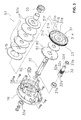
- is an exploded perspective view of the rotation transmission mechanism of the dual-bearing reel as well as of the surroundings;
- FIG. 4
- is a frontal view of the drive gear of the dual-bearing reel;
- FIG. 5
- is a cross-sectional diagram of the section line V-V in
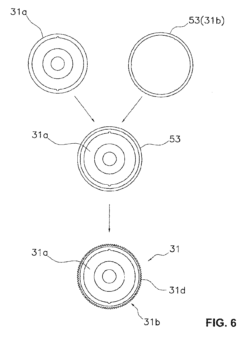
FIG. 4 ; - FIG. 6
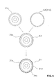
- is a diagram showing the manufacturing process of the drive gear;
- FIG. 7
- is a lateral cross-sectional diagram of a spinning reel employing the second embodiment of the present invention;
- FIG. 8
- is a cross-sectional diagram of the section line VIII-VIII in
FIG. 7 ; - FIG. 9
- is a side view of the rotation transmission mechanism of the spinning reel;
- FIG. 10
- is a cross-sectional diagram of the section line X-X in
FIG. 9 ; - FIG. 11
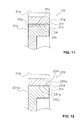
- is a diagram corresponding to
FIG. 5 of another embodiment; - FIG. 12
- is a diagram corresponding to
FIG. 5 of another embodiment; and - FIG. 13
- is a diagram corresponding to
FIG. 5 of yet another embodiment. - Selected embodiments will now be explained with reference to the drawings. It will be apparent to those skilled in the art from this disclosure that the following descriptions of the embodiments are provided for illustration only and not for the purpose of limiting the invention as defined by the appended claims and their equivalents.
- In
FIG. 1 , a dual-bearing reel employing the first embodiment of the present invention is, for example, a medium-sized round reel used for jigging. The round reel comprises a reel body 1, ahandle 2 for rotating a spool that is disposed on the side of the reel body 1, and astar drag 3 that is disposed on the reel body 1 side of thehandle 2. A spool 15 is rotatably mounted on the reel body 1. The reel body 1 can be mounted to the fishing rod R via a fishingrod mounting leg 4. - The reel body 1, as shown in
FIG. 2 comprises aframe 5, afirst side cover 13, asecond side cover 14, and amechanism mounting plate 16. Theframe 5 comprises afirst side plate 10 and asecond side plate 11 that are disposed with a predefined gap in between them, a rearpart coupling member 12a that couples thefirst side plate 10 and thesecond side plate 11 in the rear part, a lower part coupling member 12b that couples them in the lower part, and a frontpart coupling member 12c that couples them in the front part. Thefirst side cover 13 is integrally formed with the first side plate so as to cover thefirst side plate 10 laterally. Thesecond side cover 14 is integrally formed with thesecond side plate 11 so as to cover thesecond side plate 11 laterally. Themechanism mounting plate 16 is disposed on thesecond side plate 11, and a space to house the various mechanisms mentioned below is formed between themechanism mounting plate 16 and thesecond side cover 14. - The
frame 5 is obtained through die cast molding, and thesecond side cover 14 is obtained through press molding a thin metal plate. Thefirst side plate 10, thesecond side plate 11, and thefirst side cover 13 each form a near circle when seen from the side, and the outer peripheral surface is machined using, for example, a lathe, etc. Thesecond side cover 14 and themechanism mounting plate 16, as shown inFIGS. 1 to 3 , each have a shape in which a part of the near circle, as seen from the side, protrudes in the radial direction. Thesecond side cover 14 bulges outwardly in the axial direction with the mounting part of the drive axle 30 (mentioned below) as the center. - The rear
part coupling member 12a, the lower part coupling member 12b, and the frontpart coupling member 12c are plate-like members that are integrally formed with thefirst side plate 10 and thesecond side plate 11 in a shape that follows the outer periphery of thefirst side plate 10 and thesecond side plate 11. The rearpart coupling member 12a, the lower part coupling member 12b, and the frontpart coupling member 12c couple thefirst side plate 10 and thesecond side plate 11 in three locations. In this way, by integrally forming thefirst side plate 10 and thesecond side plate 11 with the rearpart coupling member 12a, the lower part coupling member 12b, and the frontpart coupling member 12c, deformation such as sagging will not easily occur even if a large load is applied to the reel body 1, and a decrease in the reeling efficiency is suppressed. The outer peripheral part of thesecoupling members first side plate 10,second side plate 11, and thefirst side cover 13. - A fishing
rod mounting leg 4 is fixed to the lower part coupling member 12b. The fishingrod mounting leg 4 is disposed in the longitudinal direction along the center position between thefirst side plate 10 and thesecond side plate 11 of theframe 5. This center position is also the center position of the spool part of the spool 15. A syntheticresin thumb rest 17 for retaining the reel along with the fishing rod R is mounted on the rearpart coupling member 12a. - The
thumb rest 17 is formed so as to come into contact with the upper part and the rear part of the rearpart coupling member 12a, and the rear part protrudes in the radial direction outwardly from thefirst side plate 10 and thesecond side plate 11, i.e., rearward. The upper surface rear part of thethumb rest 17 is tilted while curving convexly downward. Additionally, the protrusion amount rearward of the left end and the right end of the upper surface rear part of thethumb rest 17 gradually declines toward the left side. - By installing a
thumb rest 17 with this kind of shape and by putting, for example, the left thumb on thisthumb rest 17, holding the fishing rod R with the other fingers and gripping the reel body 1 along with the fishing rod R, the fishing rod R can be reliably retained along with the reel body 1 during vertical jigging, etc. - The
handle 2, as shown inFIGS. 2 and3 , comprises acrank arm 6 that is non-rotatably mounted on the tip of thedrive axle 30 and ahandle grip 7 that is rotatably mounted to one end of thecrank arm 6 around the grip shaft axis that intersects perpendicularly with one end part of thecrank arm 6. In thehandle 2, the rotating plane of the proximal end part of thehandle grip 7 is closer to the reel body 1 side than the rotating plane of the fixed part from thecrank arm 6 to thedrive axle 30. With this, the distance between thehandle grip 7 and the fishing rod R becomes closer than in conventional configurations; the torque around the axis of the fishing rod R when thehandle grip 7 is rotated and when the fishing line is wound up decreases; and the decrease in the handle winding efficiency can be suppressed. - The spool 15, as shown in
FIG. 2 , is rotatably disposed between thefirst side plate 10 and thesecond side plate 11. The spool 15 comprises abobbin trunk 15a to which the fishing line is wound, and a pair offlanges 15b that are disposed on both sides of thebobbin trunk 15a. Aspool axle 25 is fixed to the center of thebobbin trunk 15a. Thespool axle 25 is rotatably supported independently by thereel body 13 via anaxle bearing 26a, by themechanism mounting plate 16 via anaxle bearing 26b, and by the second side cover I 4 via anaxle bearing 27b. Acasting control mechanism 36 is disposed on both ends of thespool axle 25. - In the space between the
mechanism mounting plate 16 and thesecond side cover 14 are disposed arotation transmission mechanism 20 fix transmitting the torque from thehandle 2 to the spool 15, aclutch mechanism 21 that is installed in therotation transmission mechanism 20, and aclutch operating mechanism 22 for conducting the on/off operation of theclutch mechanism 21. Therotation transmission mechanism 20 comprises a rotation control mechanism for regulating the torque when the torque is reversely transmitted from the spool 15 to the side with thehandle 2. Additionally, acentrifugal brake mechanism 24 for controlling the spool 15 that freely rotates in the line delivering direction is disposed in the center part of thesecond side plate 11. Outside of thefirst side plate 10 and inside of thefirst side cover 13 are disposed a sounding mechanism that makes a sound during the rotation of the spool 15 and a lock mechanism that completely locks the spool 15 to facilitate the breakage of the line when snagging occurs, etc. - The
rotation transmission mechanism 20, as shown inFIGS. 2 and3 , comprises adrive axle 30 on one end where thehandle 2 is fixed, adrive gear 31 that is coupled to the other end of thedrive axle 30 via therotation control mechanism 23, and apinion gear 32 that engages with thedrive gear 31. Thedrive gear 31 is one example of a reel part according to the first embodiment of the present invention. - The
drive axle 30 is disposed parallel to thespool axle 25. One end of thedrive axle 30 is rotatably supported by themechanism mounting plate 16 via anaxle bearing 35a, and the center part is rotatably supported by afirst boss part 14a of thesecond side cover 14 via anaxle bearing 35b. The rotation of thedrive axle 30 in the line delivering direction is prohibited by one-way clutches - The
drive gear 31 is rotatably mounted to one end side of thedrive axle 30 and is integrally rotatable with thedrive axle 30 via therotation control mechanism 23. Thedrive gear 31, as shown inFIGS. 3 to 5 , comprises a disc-shapedinner member 31 a that has asurface treatment layer 31 c (refer toFIG. 5 ) and an annular ring-shapedouter member 31 b that is fixed to the outer peripheral surface of theinner member 31 a and that hasmultiple gear teeth 31 d on the outer peripheral surface. Themultiple gear teeth 31 d are disposed with a gap in the circumferential direction. - The
inner member 31a is, for example, a first metallic member with a relatively small specific gravity, such as aluminum alloys and magnesium alloys. Theinner member 31a further comprises a through-hole 31e that is rotatably mounted to thedrive axle 30 and a circular outerperipheral part 31f that is fixed by press fitting to theouter member 31 b. In the case that theinner member 31a is made from an aluminum alloy or a magnesium alloy, thesurface treatment layer 31 c is a corrosion- resistant layer such as an anodic oxide layer, etc. Thesurface treatment layer 31c is formed on the entire surface of the outer surface, including the through-hole 31 e of theinner member 31 a, the outerperipheral part 31f, an engagingrecess 34a of thedetent part 34 mentioned below, a surface that intersects perpendicularly with the axis of thedrive axle 30, etc. - The
inner member 31a is formed so that the outer peripheral side to which theouter member 31h is fixed is formed to be thicker than the inner peripheral side. On the stepped surface of the thin-walled part and the thick-walled part of theinner member 31 a, of the plurality ofdrag washers 57a of adrag mechanism 57 mentioned below, is formed a pair of engagingrecesses 31 h that are rotatably mounted on thedrive axle 30 and that engage with theear parts 57b of thedrag washer 57a that has a pair ofear parts 57b on the outer peripheral part. With this, thedrive gear 31 and thedrag washer 57a will integrally rotate in the line delivering direction with respect to thedrive axle 30. - The
outer member 31 b is a second metallic member with a larger specific gravity and a higher rigidity than theinner member 31 a, for example a zinc alloy or a stainless steel alloy. Theouter member 31 b comprises a circular innerperipheral part 31 g that fits the outerperipheral part 31f of theinner member 31a. Thegear teeth 31d that are formed on the outer peripheral surface are one example of a processed part, and they are formed through machining (gear cutting) after theouter member 31 b is fixed to theinner member 31 a. Regarding thegear teeth 31 d, the number of teeth is in the range of 100 to 120 and is a helical gear with a helical angle of less than 20 degrees the pitch circle diameter is around 42 mm, and the module is 0.35. - Additionally, the
drive gear 31 further comprises adetent part 34 that is installed between theinner member 31a and theouter member 31 b, that engages with theinner member 31 a and theouter member 31b and that prevents the rotation of theinner member 31a and theouter member 31 b. In the first embodiment, thedetent part 34 comprises a plurality of engagingrecesses 34a (for example 3) that are formed as a semi-circle on the outerperipheral part 31f of theinner member 31a and a plurality of engagingprotrusions 34b (for example 3) that are formed in a semi-circle on the innerperipheral part 31 g of theouter member 31 h so as to engage with the engagingrecesses 34a. Here, since an engagingprotrusion 34b was thinly formed on theouter member 31 b in the radial direction, a decrease in the strength of theouter member 31 b can be suppressed. The plurality of engagingrecesses 34a and the plurality of engagingprotrusions 34b are disposed at equal intervals in the peripheral direction. With this, even if thedrive gear 31 rotates, the balance of the rotation will not easily become unbalanced, so a smooth rotation of thedrive gear 31 will not be inhibited. Meanwhile, the disposition of the engaging recesses and the engaging protrusions can be reversed, the engaging recesses can be installed on the outer member, and the engaging protrusions can be installed on the inner member. With the engagement of the recesses and protrusions of these engagingrecesses 34a and the engagingprotrusions 34b, the detents can be applied to stop the rotation of theouter member 31 b with respect to theinner member 31 a - As shown in
FIG. 6 , thedrive gear 31 is manufactured from aring member 53 in which configurations besides thegear teeth 31 d are formed and becomes theouter member 31 b and theinner member 31 a that have all of the configurations, including thesurface treatment layer 31 c. By press fitting theinner member 31 a to the inner peripheral part of thering member 53 while matching the phase of the engagingrecesses 34a and the engagingprotrusions 34b and by forming thegear teeth 31 d on thering member 53 after press fitting, theouter member 31 h and thedrive gear 31 are completed. Thepinion gear 32 configures therotation transmission mechanism 20 and, at the same time, functions as theclutch mechanism 21. Thepinion gear 32 comprises a cross-shapedengaging groove 32a that is formed on one end, aconstricted part 32b that is formed at the midpoint,multiple gear teeth 32c that are formed adjacent to theconstricted part 32b, and an axlebearing support part 32d that is formed on the other end. Thegear teeth 32c of thepinion gear 32 engage with thegear teeth 31 d of thedrive gear 31. The number of teeth of thegear teeth 32c of thepinion gear 32 is, for example, "18". InFIG. 3 , the number of teeth is not accurately depicted. - Since the number of teeth of the
pinion gear 32 is large, the height of the teeth of thegear teeth 32c is low. For this reason, a high engaging accuracy is required of thepinion gear 32. In order to realize the above, both ends of thepinion gear 32 are supported by the reel body 1. Specifically, one end of thepinion gear 32 on which the engaginggroove 32a is formed and the other end on which the axle bearingsupport part 32d is formed are each separately supported rotatably by themechanism mounting plate 16 via the axle bearing 27a and by thesecond boss part 14b of thesecond side cover 14 via theaxle hearing 27b. Additionally, thepinion gear 32 can move between the clutch on position diagrammed in the lower side of the spool shaft axis C inFIG. 2 and the clutch off position diagrammed on the upper side of the spool shaft axis C in the spool axial direction. - With this kind of configuration, the torque from the
handle 2 is directly transmitted to the spool 15 in a state in which theclutch mechanism 21 is turned ON. - The
clutch mechanism 21 comprises a tube-shapedpinion gear 32 that is slidably mounted on the outer peripheral part of thespool axle 25, an engaginggroove 32a that is disposed on one part of thepinion gear 32, and aclutch pin 33 that is disposed on thespool axle 25. If thepinion gear 32 is slid along thespool axle 25 and the engaginggroove 32a is engaged with theclutch pin 33, the torque is transmitted between thespool axle 25 and thepinion gear 32. This state is the coupled state (the clutch on state). If the engagement of the engaginggroove 32 and theclutch pin 33 is disengaged, the torque is not transmitted between thespool axle 25 and thepinion gear 32. This state is the cutoff state (the clutch off state). In the clutch off state, the spool 15 rotates freely. Thepinion gear 32 is biased in the direction in which the engaginggroove 32a and theclutch pin 33 engage, that is, in the clutch on state, by theclutch operating mechanism 22. - The
rotation control mechanism 23 comprises a roller-type, one-way clutch 55 that rotates thedrive axle 30 only in the line winding direction (and prohibits the rotation in the line delivering direction), adrag mechanism 57, and a pawl-type, one-way clutch 60. Thedrag mechanism 57 is a mechanism that applies a predefined braking force to the rotation in the line delivering direction of the spool 15. Thedrag mechanism 57 can adjust the drag force with thestar drag 3. Thedrag mechanism 57, as shown inFIG. 3 , comprises a plurality ofdrag washers 57a that are mounted on thedrive axle 30. A part of thedrag washers 57a is integrally and rotatably mounted on thedrive axle 30, and the rest are rotatably mounted on thedrive axle 30. - The pawl-type, one-way clutch 60 rotates the
drive axle 30 only in the line winding direction. The pawl-type, one-way clutch 60, as shown inFIGS. 2 and3 , comprises a ratchet wheel 61 that is integrally and rotatably mounted on thedrive axle 30 and aratchet pawl 62 that can engage with the ratchet wheel 61. The ratchet pawl 62 (refer toFIG. 3 ) is biased to the ratchet wheel 61 side. Theclutch operating mechanism 22 comprises aclutch operating lever 40 to switch theclutch mechanism 21 into the clutch on and clutch off states. Theclutch operating lever 40 is slidably mounted on the outer side surface of thesecond side cover 14. Theclutch operating mechanism 22 moves thepinion gear 32 into the clutch on position and the clutch off position in conjunction with the operation of theclutch operating lever 40. - With a dual-bearing reel that is configured in this way, in a
drive gear 31, theouter member 31 b is fixed to theinner member 31 a comprising asurface treatment layer 31 c, after which thegear teeth 31 d of theouter member 31 h are machined. With this, thesurface treatment layer 31 c will no longer be easily affected; therefore, the performance of thesurface treatment layer 31c can be maintained, and the accuracy of thegear teeth 31 d can remain high. Additionally, by using a material with a small specific gravity for theinner member 31 a and using that with high rigidity for theouter member 31b, the strength can be maintained, and alightweight drive gear 31 can be achieved. - In the first embodiment, the drive gear according to the first embodiment of the present invention was explained using a dual-bearing reel as an example; however, in the second embodiment, a drive gear of a spinning reel will be explained.
- A spinning reel that employs the second embodiment of the present invention is a medium-sized spinning reel. As shown in
FIG. 7 , the spinning reel comprises ahandle 101, areel body 102 that rotatably supports thehandle 101, arotor 103, and a spool 104. Therotor 103 is rotatably supported by the front part of thereel body 102. The spool 104 is for winding the fishing line to the outer peripheral surface and is disposed to be movable to the front and back betweenfirst rotor arm 131 and thesecond rotor am 132 of therotor 103. Thehandle 101 can be mounted to either the left side or the right side of thereel body 102. - The
handle 101, as shown inFIG. 7 andFIG. 8 , comprises ahandle axle 101a, ahandle arm 101b b that extends from thehandle axle 101 a in the radial direction, and ahandle grip 101 c that is rotatably installed at the tip of thehandle arm 101 b. - The
reel body 102 comprises areel body 102a that has a housing space inside whose side part opens and acover member 102b (FIG. 8 ) that is detachably mounted to thereel body 102a to plug the housing space of thereel body 102a. Additionally, thereel body 102 comprises amain body guard 126 that covers thereel body 102a and the rear part of thecover member 102b. - The
reel body 102a is, for example, made of a light alloy, such as a magnesium alloy and an aluminum alloy; a T-shaped fishingrod mounting leg 102c that extends forward and backward is integrally formed on the upper part. A mountingseat 102d to which the fishing rod R is mounted forwardly descending in the longitudinal direction is disposed on the upper part of the fishingrod mounting leg 102c. The transverse section of the mountingseat 102d is depressed curving in a circular arc shape.
Arotation transmission mechanism 105 and anoscillating mechanism 106 are installed in the housing space of thereel body 102a, as shown inFIG. 7 . - The
rotation transmission mechanism 105 transmits the rotation of thehandle 101 to therotor 103 as well as the spool 104. Therotation transmission mechanism 105 rotates therotor 103 in conjunction with the rotation of thehandle 101 and moves the spool 104 forward and backward. Therotation transmission mechanism 105, as shown inFIGS. 8 and9 , comprises adrive axle 110 with which thehandle axle 101 a of thehandle 101 is integrally and rotatably coupled, adrive gear 111 consisting of a face gear that rotates along with thedrive axle 110, and apinion gear 112 that engages with thisdrive gear 111. Thedrive gear 111 is one example of a reel part according to the second embodiment.
As shown inFIG. 9 , thedrive gear 111 is formed integrally with or separately from (integrally in this embodiment) thedrive axle 110. Thedrive axle 110 is integrally and rotatably coupled with thehandle axle 101 a by a threaded coupling or a noncircular engagement (a threaded coupling in this embodiment). Thedrive axle 110 is rotatably mounted to thereel body 102 by an axle bearing 127a that is mounted on acover member 102b and anaxle bearing 127b that is mounted on thereel body 102a. A left female threadedpart 110a and a right female threadedpart 110b that screw onto thehandle axle 101 a are formed on the inner peripheral surface of both ends of the drive axle. Here, the left female threadedpart 110a on the near side of thedrive gear 111 is a left screw, and the right female threadedpart 110b that is on the far side of thedrive gear 111 is a right screw. Therefore, there are two kinds of handle axes 101a that are prepared, one for the right screw and another for the left screw. - The
drive gear 111, as shown inFIGS. 8 ,9 and 10 , comprises aninner member 111a that is integrally formed with thedrive axle 110 and that has asurface treatment layer 111c (refer toFIG. 10 ); and an annular ring-shapedouter member 111 b that is fixed on the outer peripheral side of theinner member 111a and that has multipleface gear teeth 111d on one side surface of the outer peripheral side. The multipleface gear teeth 111d are disposed with a gap in the circumferential direction. - The
inner member 111 a, along with thedrive axle 110, is a first metallic member with a relatively small specific gravity, such as an aluminum alloy and a magnesium alloy. Theinner member 111a is formed by casting the first metal, after which asurface treatment layer 111c is formed. Theinner member 111 a comprises a circular outerperipheral part 111f that is fixed to theouter member 111b by press fitting. In the case that theinner member 111a is made from an aluminum alloy or a magnesium alloy, thesurface treatment layer 111c is a corrosion-resistant layer such as an anodic oxide layer, etc. Thesurface treatment layer 111 c is formed on the entire surface of the outer surface, including an outerperipheral part 111f of theinner member 111a, a semi-circular firstengaging recess 135a with which adetent part 134 mentioned below engages, and a surface that intersects perpendicularly with the axis of thedrive axle 110, etc. - The
outer member 111 b is a second metallic member with a larger specific gravity and a higher rigidity than theinner member 111 a, for example a zinc alloy or a stainless steel alloy. Theouter member 111b further comprises a circular innerperipheral part 111g that fits the outerperipheral part 111f of theinner member 111 a. Theface gear teeth 111d formed on the outer peripheral surface are one example of a processed part, and they are formed through casting after theouter member 111 b is fixed to theinner member 111 a. The number of teeth of theface gear teeth 111d is, for example, between 50 and 70; the outer diameter is, for example, around 26 mm; and the inner diameter is, for example, around 21 mm. - Additionally, the
drive gear 111 further comprises adetent part 134 that is installed between theinner member 111 a and theouter member 111 b and that engages with theinner member 111 a and theouter member 111 b and prevents the rotation of theinner member 111 a and theouter member 111 b. In the second embodiment, thedetent part 134 comprises a plurality of rotation brake pins 134a (for example, 4) that engage with theinner member 111a and theouter member 111 b. Therefore, in the second embodiment, thedetent part 134 is installed separately from theinner member 111a and theouter member 111 b. Therotation brake pins 134a fit a through-hole 135 that is formed from a plurality of first engagingrecesses 135a (for example 4) that are formed as a semi-circle on the outerperipheral part 111f of theinner member 111a a and a plurality of secondengaging recesses 135b (for example 4) that are formed in a semi-circle on theinner member 111g of theouter member 111 b. Therotation brake pin 134a is stopped in the through-hole 135 by caulk fixing that presses both ends and plastically deforms them. The plurality of through-holes 135 is disposed in the circumferential direction at equal intervals. With this, even if thedrive gear 111 rotates, the balance of the rotation will not easily become unbalanced; therefore, a smooth rotation of thedrive gear 111 will not be inhibited. Thepinion gear 112, as shown inFIG. 9 , comprises a tube-shaped gearmain body 112a andgear part 112b that comprises ahelical gear 112c and that is formed on the rear part outer peripheral surface of the gearmain body 112a. The gearmain body 112a is rotatably mounted on thered body 102a around an axis that crisscrosses thehandle axle 101 a (around the spool axle 115). The gearmain body 112a, as shown inFIG. 7 , is rotatably supported by areel body 102a by a front axle bearing 114a and a rear axle bearing 114b in the vicinity of thegear part 112b. Thespool axle 115 can penetrate the center of the gearmain body 112a. Anut 113 for fixing therotor 103 screws onto the front end outer peripheral surface for the gearmain body 112a. Therotor 103 is integrally and rotatably coupled to the front part outer peripheral surface of the gearmain body 112a. - The
oscillating mechanism 106, as shown inFIGS. 7 and8 , is a mechanism for moving aspool axle 115 that is coupled to the center part of the spool 104 via adrag mechanism 160 forward and backward to move the spool 104 in the same direction. Theoscillating mechanism 106 comprises atraverse camshaft 121 that is disposed in parallel under thespool axle 115, aslider 122 that is guided to thereel body 102a in the longitudinal direction along thetraverse camshaft 121, and anintermediate gear 123 that is fixed to the tip of thetraverse camshaft 121. Theslider 122 is fixed non-rotatably to the rear end of thespool axle 115. Anintermediate gear 123 engages with thepinion gear 112. - The
rotor 103, as shown inFIG. 7 , is a light alloy such as a magnesium alloy and an aluminum alloy, is non-rotatably coupled to thepinion gear 112, and is rotatable with respect to thereel body 102. Therotor 103 comprises atube section 130 that is integrally and rotatably coupled with thepinion gear 112, and afirst rotor arm 131 and asecond rotor arm 132 that are connected to a position facing the rear part of thetube section 130 and that extend forward with a space between them and thetube section 130. - The
tube section 130 comprises a disc-shapedwall part 130d on the front part inner peripheral side, and anannular boss section 130e that is integrally and rotatably coupled with thepinion gear 112 formed in the center part of thewall part 130d. The front part of thepinion gear 112 penetrates the inner peripheral part of thisboss section 130e, and theboss section 130e is integrally and rotatably locked to the front part of thepinion gear 112. By screwing in thenut 113 into thepinion gear 112 in this state, therotor 103 is fixed to thepinion gear 112. Abail arm 144 that guides the fishing line to the spool 104 in the line releasing direction and the line winding direction is slidably mounted on the outer peripheral side of the tip of thefirst rotor arm 131. - A reverse
rotation prevention mechanism 150 is disposed inside of thetube section 130 of therotor 103 for prohibiting / releasing the reverse rotation of therotor 103. The reverserotation prevention mechanism 150 has a roller-type, one-way clutch 151 whose inner ring idles and a switchinglever 152 that switches the one-way clutch 151 between the operating state (the reverse rotation prohibited state) and the non-operating state (the reverse rotation permitted state). The switchinglever 152 is slidably mounted on thereel body 102a. A cam, which is not diagrammed, is installed on the tip of the switchinglever 152; if the switchinglever 152 is oscillated, the one-way clutch 151 switches between the operating state and the non-operating state due to the cam. - The spool 104, as shown in
FIG. 7 , is disposed between thefirst rotor arm 131 and thesecond rotor arm 132 of therotor 103 and is mounted to the tip of thespool axle 115 via adrag mechanism 160. The spool 104 comprises abobbin trunk 104a, the outer periphery to which is wound the fishing line, a tube-shapedskirt section 104c that is integrally formed with thebobbin trunk 104a at the rear of thebobbin trunk 104a, and a large-diameter flange part 104b that is installed on the front end of thebobbin trunk 104a. - The
drag mechanism 160 brakes the rotation of the spool 104 and comprises adrag adjustment knob 161 that is screwed onto the tip of thespool 115 and a braking section 162 that is pressed by thedrag adjustment knob 161 and that brakes the spool 104. - With a spinning reel that is configured in this way, in a
drive gear 111, theface gear teeth 111 d of theouter member 111 b are cast after fixing the outer member 111h to theinner member 111 a, which has asurface treatment layer 111 c. With this, thesurface treatment layer 111c will no longer be easily affected; therefore, the performance of thesurface treatment layer 111c can be maintained, and the accuracy of thegear teeth 111d can remain high. Additionally, by using a material with a small specific gravity for theinner member 111 a and by using that with high rigidity for theouter member 111 b, the strength can be maintained, and alightweight drive gear 111 can be achieved. - The embodiments of the present invention were described above, but the present invention is not limited to the above-described embodiments; various modifications can be made without departing from the scope of the invention. Specifically, the various embodiments and modified examples described in the present specification can be freely combined according to necessity.
In the following explanation, members with configurations that differ from the first embodiment are expressed by adding a number in the hundreds digit to the reference symbols in the first embodiment. Thus, regarding members with the same configuration, the same reference symbols are used as the members in the first embodiment. - (a) In the aforementioned embodiments, the
inner member 31 a (or 111a) is fixed by press fitting, but the present invention is not limited to this configuration. In thedrive gear 231 shown inFIG. 11 , theinner member 31 a is adhered to theouter member 31 h by an appropriate adhesive agent. Meanwhile, thedetent part 34 has the same configuration as in the first embodiment. In this case, an adhesive reservoir with a recess that can store the adhesive agent can be installed in either the outerperipheral part 31f of theinner member 31a or in the innerperipheral part 31g of theouter member 31b. - (b) With the
drive gear 331 shown inFIG. 12 , theinner member 331 a comprises a male threaded part 331i in the outerperipheral part 331f, and theouter member 331 b comprises a female threadedpart 33 1j that screws into the male threaded part 331 i in the inner peripheral part 331 g. Here, theinner member 331 a and theouter member 331 b are fixed by a threaded engagement. In this case, due to the rotation braking, caulk fixing both end parts of the outerperipheral part 331f of theinner member 331 a to theouter member 331 b by plastic deformation is preferable. - (c) With the drive gear 431 shown in
FIG. 13 , the outer member 431 b is fixed by the plastic deformation of the inner member 431 a with respect to the outer member 431 b. Specifically, by plastically deforming both end parts of the outer peripheral part 431 of the inner member 431 a toward the outer member 431 b, the outer member 431 b is fixed to the inner member 431 a. - (d) In the aforementioned embodiments, the shape of the detent part was configured to be circular, but the present invention is not limited to this configuration. The configuration of the detent part can be any shape, so long as the shape can prevent the rotation of the inner member and the outer member.
- (e) In the aforementioned embodiment, for the
outer member 31 b (or 111b) havinggear teeth 31d (orface gear teeth 111 d) as the processed part, zinc alloys and stainless steel alloys were used as examples, but the present invention is not limited to this configuration. The outer member can be anything as long as the metal has a larger specific gravity and a higher rigidity than that of the inner member. - The embodiments described above can be expressed as the following.
- (A) The drive gear 31 (or 111) as the reel part comprises an
inner member 31 a (or 111a) and anouter member 31 b (or 111b). The inner member (or 111a) comprises asurface treatment layer 31c (or 111c). Theouter member 31b (or 111b) comprisesgear teeth 31d (orface gear teeth 111d) that are fixed on the outer peripheral side of theinner member 31 a (or 111a) and are processed after they are fixed to theinner member 31a (or 111a). - In this drive gear 31 (or 111), the
gear teeth 31 d (orface gear teeth 111 d) of theouter member 31 b (or 111 b) are processed after fixing theouter member 31 b (or 111 b) to theinner member 31 a (or 111 a) that has asurface treatment layer 31 c (or 111c). With this, thesurface treatment layer 31c (or 111c) will no longer be affected; therefore, the performance of thesurface treatment layer 31c (or 111c) can be maintained, and the accuracy of thegear teeth 31 d (orface gear teeth 111 d) can remain high. Additionally, by using a material with a small specific gravity for theinner member 31 a (or 111 a) and by using that with high rigidity for the outer member, the strength can be maintained, and a light weight can be achieved. - (B) The processed part can comprise
gear teeth 31 d (orface gear teeth 111 d). In this case, the strength of thegear teeth 31 d (orface gear teeth 111 d) can be maintained. - (C) The
gear teeth 31d can also be formed by machining. In this case, thegear teeth 31d can be formed with a high degree of accuracy. - (D) The
gear teeth 111d can also be formed by casting. In this case, theface gear teeth 111d, which increase the cost when formed by machining, can be formed while suppressing an in cost. - (E) The
inner member 31 a (or 111 a) can be made from a first metal having a corrosion- increase resistant layer as thesurface treatment layer 31c (or 111 c), and theouter member 31 b (or 111 b) can havegear teeth 31d (orface gear teeth 111 d) and can be made from a second metal that has a specific gravity that is larger and a rigidity that is higher than the first metall. In this case, lightweight gears can be achieved while the strength and corrosion resistance of thegear teeth 31d (or face gear teeth 11Id) are maintained. - (F) The
inner member 31 a (or 111 a) can fit theouter member 31 b (or 111 b) and can be fixed to theouter member 31 b (or 111 b) by press fitting. In this case, theinner member 31 a (or 111 a) and theouter member 31 b (or 111 b) can be solidly fixed by press fitting. - (G) The
inner member 31 a (or 111 a) can be fixed to theouter member 31 b (or 111 b) by plastic deformation towards theouter member 31 b (or 111 b). In this case, for example, theinner member 31 a (or 111 a) and theouter member 31 b (or 111 b) can be solidly fixed by plastic deformation, such as caulk fixing, etc. - (H) The
inner member 31 a (or 111a) can be fixed to theouter member 31 b (or 111 b) by bonding. In this case, theinner member 31 a (or 111 a) and theouter member 31 b (or 111 b) can be easily fixed. Additionally, by combining the fixing and bonding by press fitting or plastic deformation mentioned above, theinner member 31 a (or 111 a) and theouter member 31 b (or 111 b) can be more solidly fixed. - (I) The
inner member 331a can comprise a male threaded part 331 i, and theouter member 331 b can comprise a female threaded part 331j that screws into the male threaded part 331i. In this case, theinner member 331 a and theouter member 331 b can be easily fixed by a threaded engagement. - (J) The
inner member 31a (or 111a) and the outer member can each comprise a detent part 34 (or 134) to engage with each other and to prevent the rotation. In this case, since the brakes will he applied to stop the rotation of theinner member 31 a (or 111 a) and theouter member 31 b (or 111 b), even if theinner member 31 a (or 111 a) and theouter member 31 b (or 111 b) are fixed by press fitting, elastic deformation, bonding, etc., theinner member 31 a (or 111a) andouter member 31 b (or 111b) can be reliably rotated integrally. - (K) The
inner member 31 a (or 111 a) can be mounted on a drive axle 30 (or 110) that rotates in conjunction with a handle 2 (or 101) of the fishing reel, and thegear teeth 31 d (or theface gear teeth 111 d) of theouter member 31 b (or 111 b) can engage with a pinion gear 32 (or 112) that rotates around a spool axle 25 (or 115) of the fishing reel. In this case, a lightweight drive gear 31 (or 111) can be achieved while maintaining the accuracy, the strength, and the surface treatment layer performance of the drive gear 31 (or 111) of a dual-bearing reel, a spinning reel or a single-bearing reel. - (L) The fishing reel can be a dual-bearing reel that has a spool 15 that rotates around a shaft axis that is parallel to the shaft axis of the
handle 2. Theinner member 31 a is rotatably mounted on adrive axle 30 in conjunction with adrive axle 30 of a dual -bearing reel. In this case, in a dual-bearing reel, alightweight drive gear 31 can be achieved while maintaining the accuracy, strength, and surface treatment layer performance of thedrive gear 31. - (M) The fishing reel can be a spinning reel having a spool 104 that moves forward and backward in the axial direction that crisscrosses with the shaft axis of the
handle 101, and theinner member 111 a can be integrally and rotatably mounted on thedrive axle 110 of the spinning reel. In this case, in a spinning reel, alightweight drive gear 111 can he achieved while maintaining the accuracy, strength, and surface treatment layer performance of thedrive gear 111.
Claims (13)
- A reel part for a fishing reel comprising:an inner member having a surface treatment layer, andan outer member fixed to an outer peripheral side of the inner member, the outer member including a processed part that is processed after being fixed to the inner member.
- The reel part according to claim 1, wherein the processed part comprises a plurality of gear teeth.
- The reel part as recited in claim 2, wherein the gear teeth are machined gear teeth.
- The reel part as recited in claim 2, wherein the gear teeth are casted gear teeth.
- The reel part as recited in any one of claims 2 to 4, wherein the inner member is a first metal having a corrosion-resistant layer as the surface treatment layer, and the outer member is a second metal with a larger specific gravity and a higher rigidity than the first metal, the gear teeth are made of the second metal.
- The reel part as recited in any one of claims 2 to 5, wherein the inner member is press fitted to the outer member.
- The reel part as recited in any one of claims 2 to 6, wherein the inner member is plastically deformed to the outer member to fix the inner member to the outer member.
- The reel part as recited in any one of claims 2 to 7, wherein the inner member is bonded to the outer member.
- The reel part as recited in any one of claims 2 to 5, wherein the inner member includes a male threaded part, and the outer member includes a female threaded part screwed into the female threaded part.
- The reel part as recited in any one of claims 2 to 9, further comprising a detent part that is installed between the inner member and the outer member and that engages with the inner member and the outer member and prevents a rotation of the inner member and the outer member.
- The reel part as recited in any one of claims 2 to 10, wherein the inner member is configured to be mounted to a drive axle that rotates in conjunction with a handle of the fishing reel, and the gear teeth of the outer member are configured to engage with a pinion gear that rotates around a spool axis of the fishing reel.
- A dual-bearing reel including the reel part as recited in claim 2, and further comprising
a handle;
a drive axle operatively coupled to the handle; and
a spool that rotates around a spool axis that is parallel to an axis of the drive axle,
the inner member being mounted to the drive axle that rotates in conjunction with the drive axle,
the gear teeth of the outer member being engaged with a pinion gear that rotates around the spool axis. - A spinning reel including the reel part as recited in claim 2, and further comprising
a handle;
a drive axle operatively coupled to the handle; and
a spool that rotates around a spool axis and moves forward and backward in an axial direction of the spool axis, the spool axis being transverse to an axis of the drive axle, and
the inner member being integrally and rotatably mounted on the drive axle,
the gear teeth of the outer member being engaged with a pinion gear that rotates around the spool axis.
Applications Claiming Priority (1)
| Application Number | Priority Date | Filing Date | Title |
|---|---|---|---|
| JP2013073705A JP6411009B2 (en) | 2013-03-29 | 2013-03-29 | Reel parts for fishing reels |
Publications (2)
| Publication Number | Publication Date |
|---|---|
| EP2784353A1 true EP2784353A1 (en) | 2014-10-01 |
| EP2784353B1 EP2784353B1 (en) | 2017-10-25 |
Family
ID=50190273
Family Applications (1)
| Application Number | Title | Priority Date | Filing Date |
|---|---|---|---|
| EP14156732.1A Active EP2784353B1 (en) | 2013-03-29 | 2014-02-26 | Reel part for fishing reel |
Country Status (7)
| Country | Link |
|---|---|
| US (1) | US9468199B2 (en) |
| EP (1) | EP2784353B1 (en) |
| JP (1) | JP6411009B2 (en) |
| KR (1) | KR102155853B1 (en) |
| CN (1) | CN104067994B (en) |
| MY (1) | MY187428A (en) |
| TW (1) | TWI623265B (en) |
Cited By (2)
| Publication number | Priority date | Publication date | Assignee | Title |
|---|---|---|---|---|
| CN112984077A (en) * | 2021-02-04 | 2021-06-18 | 杭州筝友户外用品有限公司 | Speed change gear and kite wheel and fishing wheel with same |
| US12490728B2 (en) * | 2022-05-02 | 2025-12-09 | Shimano Inc. | Oscillating mechanism for spinning reel and spinning reel with oscillating mechanism |
Families Citing this family (13)
| Publication number | Priority date | Publication date | Assignee | Title |
|---|---|---|---|---|
| JP6198539B2 (en) * | 2013-09-13 | 2017-09-20 | 株式会社シマノ | Double bearing reel |
| JP6284497B2 (en) * | 2015-03-24 | 2018-02-28 | グローブライド株式会社 | Double bearing type reel |
| EP3298890B1 (en) * | 2015-05-18 | 2020-05-06 | Ningbo Zhongyuan Alljoy Fishing Tackle Co., Ltd. | Fishing reel with single-handedly assembled and disassembled rocker arm assembly |
| JP6640552B2 (en) * | 2015-12-22 | 2020-02-05 | 株式会社シマノ | Double bearing reel |
| JP2017176111A (en) | 2016-03-31 | 2017-10-05 | グローブライド株式会社 | Reel for fishing |
| JP2018113919A (en) * | 2017-01-19 | 2018-07-26 | 株式会社シマノ | Double bearing reel |
| JP6955350B2 (en) | 2017-03-13 | 2021-10-27 | 株式会社シマノ | Pinion gear and spinning reel |
| JP6914207B2 (en) * | 2018-01-12 | 2021-08-04 | グローブライド株式会社 | Manufacturing method of components of fishing reel |
| US11173568B2 (en) * | 2018-07-11 | 2021-11-16 | GM Global Technology Operations LLC | Composite metal flexplate |
| JP7133417B2 (en) * | 2018-09-26 | 2022-09-08 | 株式会社シマノ | Spinning reel sounding mechanism and spinning reel |
| WO2022249432A1 (en) * | 2021-05-28 | 2022-12-01 | 三菱電機株式会社 | Rotor, rotary machine using rotor, and method for producing rotor |
| US12484564B2 (en) * | 2022-01-27 | 2025-12-02 | TrikaUSA Inc. | Anti-reverse mechanism for fishing reel |
| WO2024028944A1 (en) * | 2022-08-01 | 2024-02-08 | 株式会社スタジオオーシャンマーク | Fishing reel |
Citations (6)
| Publication number | Priority date | Publication date | Assignee | Title |
|---|---|---|---|---|
| US3530735A (en) * | 1968-09-17 | 1970-09-29 | Alton K Allen | Precision gear and blank for manufacture of the same |
| JPH10150889A (en) | 1996-11-22 | 1998-06-09 | Shimano Inc | Spinning reel face gear |
| US6343418B1 (en) * | 1997-11-20 | 2002-02-05 | Shimano Inc. | Spinning reel face gear manufacturing method |
| JP2003235413A (en) * | 2002-02-20 | 2003-08-26 | Shimano Inc | Gear parts for fishing reel |
| US20110250070A1 (en) * | 2008-12-10 | 2011-10-13 | Vestas Wind Systems A/S | Composite gear part for a gear arrangement and a method of forming a composite gear part |
| EP2494866A1 (en) * | 2011-03-04 | 2012-09-05 | Shimano Inc. | Spool of fishing reel |
Family Cites Families (12)
| Publication number | Priority date | Publication date | Assignee | Title |
|---|---|---|---|---|
| JP2724630B2 (en) * | 1990-05-16 | 1998-03-09 | 株式会社久保田鉄工所 | Rotating body manufacturing method |
| JP3854732B2 (en) * | 1998-09-17 | 2006-12-06 | 株式会社シマノ | Spinning reel master gear |
| JP3839972B2 (en) * | 1998-09-17 | 2006-11-01 | 株式会社シマノ | Spinning reel waterproof structure |
| JP2000312549A (en) * | 1999-04-30 | 2000-11-14 | Daiwa Seiko Inc | Components of fishing reel |
| JP2003166097A (en) * | 2001-11-28 | 2003-06-13 | Shimano Inc | Fishing parts |
| US20040021022A1 (en) * | 2002-08-02 | 2004-02-05 | Daiwa Seiko, Inc. | Face gear and method of manufacturing the same |
| JP2004141103A (en) * | 2002-10-25 | 2004-05-20 | Shimano Inc | Spool for dual-bearing reel |
| SG118339A1 (en) * | 2004-06-09 | 2006-01-27 | Shimano Kk | Spinning-reel sounding mechanism |
| JP2007159427A (en) * | 2005-12-09 | 2007-06-28 | Shimano Inc | Part for fishing |
| JP2011193855A (en) * | 2010-03-24 | 2011-10-06 | Shimano Components Malaysia Sdn Bhd | Master gear assembly |
| JP5777873B2 (en) * | 2010-11-18 | 2015-09-09 | 株式会社シマノ | Fishing reel gear mounting structure |
| JP6219702B2 (en) * | 2013-12-16 | 2017-10-25 | 株式会社シマノ | Fishing reel drive gear and fishing reel pinion gear |
-
2013
- 2013-03-29 JP JP2013073705A patent/JP6411009B2/en active Active
-
2014
- 2014-01-20 KR KR1020140006650A patent/KR102155853B1/en not_active Expired - Fee Related
- 2014-02-10 TW TW103104305A patent/TWI623265B/en active
- 2014-02-17 US US14/181,921 patent/US9468199B2/en active Active
- 2014-02-26 EP EP14156732.1A patent/EP2784353B1/en active Active
- 2014-03-05 MY MYPI2014700511A patent/MY187428A/en unknown
- 2014-03-28 CN CN201410121436.6A patent/CN104067994B/en active Active
Patent Citations (6)
| Publication number | Priority date | Publication date | Assignee | Title |
|---|---|---|---|---|
| US3530735A (en) * | 1968-09-17 | 1970-09-29 | Alton K Allen | Precision gear and blank for manufacture of the same |
| JPH10150889A (en) | 1996-11-22 | 1998-06-09 | Shimano Inc | Spinning reel face gear |
| US6343418B1 (en) * | 1997-11-20 | 2002-02-05 | Shimano Inc. | Spinning reel face gear manufacturing method |
| JP2003235413A (en) * | 2002-02-20 | 2003-08-26 | Shimano Inc | Gear parts for fishing reel |
| US20110250070A1 (en) * | 2008-12-10 | 2011-10-13 | Vestas Wind Systems A/S | Composite gear part for a gear arrangement and a method of forming a composite gear part |
| EP2494866A1 (en) * | 2011-03-04 | 2012-09-05 | Shimano Inc. | Spool of fishing reel |
Cited By (2)
| Publication number | Priority date | Publication date | Assignee | Title |
|---|---|---|---|---|
| CN112984077A (en) * | 2021-02-04 | 2021-06-18 | 杭州筝友户外用品有限公司 | Speed change gear and kite wheel and fishing wheel with same |
| US12490728B2 (en) * | 2022-05-02 | 2025-12-09 | Shimano Inc. | Oscillating mechanism for spinning reel and spinning reel with oscillating mechanism |
Also Published As
| Publication number | Publication date |
|---|---|
| KR102155853B1 (en) | 2020-09-14 |
| CN104067994A (en) | 2014-10-01 |
| TW201438571A (en) | 2014-10-16 |
| TWI623265B (en) | 2018-05-11 |
| EP2784353B1 (en) | 2017-10-25 |
| MY187428A (en) | 2021-09-22 |
| CN104067994B (en) | 2019-09-20 |
| KR20140118702A (en) | 2014-10-08 |
| US9468199B2 (en) | 2016-10-18 |
| JP2014197986A (en) | 2014-10-23 |
| JP6411009B2 (en) | 2018-10-24 |
| US20140291430A1 (en) | 2014-10-02 |
Similar Documents
| Publication | Publication Date | Title |
|---|---|---|
| EP2784353B1 (en) | Reel part for fishing reel | |
| JP2014197986A5 (en) | ||
| KR101979018B1 (en) | Fishing-reel reel unit and fishing reel | |
| KR102294431B1 (en) | Dual-bearing reel pinion gear and dual-bearing reel | |
| JP2013099265A5 (en) | ||
| KR102405035B1 (en) | Clutch return mechanism for dual bearing reel | |
| EP2494866B1 (en) | Spool of fishing reel | |
| EP2578080B1 (en) | Fishing-reel reel unit and fishing reel | |
| JP2015126703A5 (en) | ||
| US9089118B2 (en) | Drive gear | |
| EP2425713B1 (en) | Dual-bearing reel | |
| EP2594131A1 (en) | Handle assembly for dual-bearing reel and dual-bearing reel | |
| KR101998090B1 (en) | Fishing-reel reel unit, fishing reel and method of manufacturing fishing-reel reel unit | |
| KR102927192B1 (en) | Dual-bearing reel | |
| JP2001161228A (en) | Spinning reel spool |
Legal Events
| Date | Code | Title | Description |
|---|---|---|---|
| 17P | Request for examination filed |
Effective date: 20140226 |
|
| AK | Designated contracting states |
Kind code of ref document: A1 Designated state(s): AL AT BE BG CH CY CZ DE DK EE ES FI FR GB GR HR HU IE IS IT LI LT LU LV MC MK MT NL NO PL PT RO RS SE SI SK SM TR |
|
| AX | Request for extension of the european patent |
Extension state: BA ME |
|
| PUAI | Public reference made under article 153(3) epc to a published international application that has entered the european phase |
Free format text: ORIGINAL CODE: 0009012 |
|
| R17P | Request for examination filed (corrected) |
Effective date: 20150327 |
|
| RBV | Designated contracting states (corrected) |
Designated state(s): AL AT BE BG CH CY CZ DE DK EE ES FI FR GB GR HR HU IE IS IT LI LT LU LV MC MK MT NL NO PL PT RO RS SE SI SK SM TR |
|
| REG | Reference to a national code |
Ref country code: DE Ref legal event code: R079 Ref document number: 602014016161 Country of ref document: DE Free format text: PREVIOUS MAIN CLASS: F16H0055060000 Ipc: A01K0089000000 |
|
| GRAP | Despatch of communication of intention to grant a patent |
Free format text: ORIGINAL CODE: EPIDOSNIGR1 |
|
| RIC1 | Information provided on ipc code assigned before grant |
Ipc: A01K 89/015 20060101ALI20170615BHEP Ipc: F16H 55/06 20060101ALN20170615BHEP Ipc: A01K 89/01 20060101ALI20170615BHEP Ipc: F16H 55/17 20060101ALN20170615BHEP Ipc: A01K 89/00 20060101AFI20170615BHEP |
|
| INTG | Intention to grant announced |
Effective date: 20170706 |
|
| RIC1 | Information provided on ipc code assigned before grant |
Ipc: F16H 55/06 20060101ALN20170626BHEP Ipc: A01K 89/00 20060101AFI20170626BHEP Ipc: F16H 55/17 20060101ALN20170626BHEP Ipc: A01K 89/01 20060101ALI20170626BHEP Ipc: A01K 89/015 20060101ALI20170626BHEP |
|
| GRAS | Grant fee paid |
Free format text: ORIGINAL CODE: EPIDOSNIGR3 |
|
| GRAA | (expected) grant |
Free format text: ORIGINAL CODE: 0009210 |
|
| AK | Designated contracting states |
Kind code of ref document: B1 Designated state(s): AL AT BE BG CH CY CZ DE DK EE ES FI FR GB GR HR HU IE IS IT LI LT LU LV MC MK MT NL NO PL PT RO RS SE SI SK SM TR |
|
| REG | Reference to a national code |
Ref country code: GB Ref legal event code: FG4D |
|
| REG | Reference to a national code |
Ref country code: CH Ref legal event code: EP |
|
| REG | Reference to a national code |
Ref country code: AT Ref legal event code: REF Ref document number: 938995 Country of ref document: AT Kind code of ref document: T Effective date: 20171115 |
|
| REG | Reference to a national code |
Ref country code: IE Ref legal event code: FG4D |
|
| REG | Reference to a national code |
Ref country code: DE Ref legal event code: R096 Ref document number: 602014016161 Country of ref document: DE |
|
| REG | Reference to a national code |
Ref country code: FR Ref legal event code: PLFP Year of fee payment: 5 |
|
| REG | Reference to a national code |
Ref country code: NL Ref legal event code: MP Effective date: 20171025 |
|
| REG | Reference to a national code |
Ref country code: LT Ref legal event code: MG4D |
|
| REG | Reference to a national code |
Ref country code: AT Ref legal event code: MK05 Ref document number: 938995 Country of ref document: AT Kind code of ref document: T Effective date: 20171025 |
|
| PG25 | Lapsed in a contracting state [announced via postgrant information from national office to epo] |
Ref country code: NL Free format text: LAPSE BECAUSE OF FAILURE TO SUBMIT A TRANSLATION OF THE DESCRIPTION OR TO PAY THE FEE WITHIN THE PRESCRIBED TIME-LIMIT Effective date: 20171025 |
|
| PG25 | Lapsed in a contracting state [announced via postgrant information from national office to epo] |
Ref country code: NO Free format text: LAPSE BECAUSE OF FAILURE TO SUBMIT A TRANSLATION OF THE DESCRIPTION OR TO PAY THE FEE WITHIN THE PRESCRIBED TIME-LIMIT Effective date: 20180125 Ref country code: SE Free format text: LAPSE BECAUSE OF FAILURE TO SUBMIT A TRANSLATION OF THE DESCRIPTION OR TO PAY THE FEE WITHIN THE PRESCRIBED TIME-LIMIT Effective date: 20171025 Ref country code: LT Free format text: LAPSE BECAUSE OF FAILURE TO SUBMIT A TRANSLATION OF THE DESCRIPTION OR TO PAY THE FEE WITHIN THE PRESCRIBED TIME-LIMIT Effective date: 20171025 Ref country code: FI Free format text: LAPSE BECAUSE OF FAILURE TO SUBMIT A TRANSLATION OF THE DESCRIPTION OR TO PAY THE FEE WITHIN THE PRESCRIBED TIME-LIMIT Effective date: 20171025 Ref country code: ES Free format text: LAPSE BECAUSE OF FAILURE TO SUBMIT A TRANSLATION OF THE DESCRIPTION OR TO PAY THE FEE WITHIN THE PRESCRIBED TIME-LIMIT Effective date: 20171025 |
|
| PG25 | Lapsed in a contracting state [announced via postgrant information from national office to epo] |
Ref country code: GR Free format text: LAPSE BECAUSE OF FAILURE TO SUBMIT A TRANSLATION OF THE DESCRIPTION OR TO PAY THE FEE WITHIN THE PRESCRIBED TIME-LIMIT Effective date: 20180126 Ref country code: IS Free format text: LAPSE BECAUSE OF FAILURE TO SUBMIT A TRANSLATION OF THE DESCRIPTION OR TO PAY THE FEE WITHIN THE PRESCRIBED TIME-LIMIT Effective date: 20180225 Ref country code: HR Free format text: LAPSE BECAUSE OF FAILURE TO SUBMIT A TRANSLATION OF THE DESCRIPTION OR TO PAY THE FEE WITHIN THE PRESCRIBED TIME-LIMIT Effective date: 20171025 Ref country code: BG Free format text: LAPSE BECAUSE OF FAILURE TO SUBMIT A TRANSLATION OF THE DESCRIPTION OR TO PAY THE FEE WITHIN THE PRESCRIBED TIME-LIMIT Effective date: 20180125 Ref country code: AT Free format text: LAPSE BECAUSE OF FAILURE TO SUBMIT A TRANSLATION OF THE DESCRIPTION OR TO PAY THE FEE WITHIN THE PRESCRIBED TIME-LIMIT Effective date: 20171025 Ref country code: LV Free format text: LAPSE BECAUSE OF FAILURE TO SUBMIT A TRANSLATION OF THE DESCRIPTION OR TO PAY THE FEE WITHIN THE PRESCRIBED TIME-LIMIT Effective date: 20171025 Ref country code: RS Free format text: LAPSE BECAUSE OF FAILURE TO SUBMIT A TRANSLATION OF THE DESCRIPTION OR TO PAY THE FEE WITHIN THE PRESCRIBED TIME-LIMIT Effective date: 20171025 |
|
| REG | Reference to a national code |
Ref country code: DE Ref legal event code: R097 Ref document number: 602014016161 Country of ref document: DE |
|
| PG25 | Lapsed in a contracting state [announced via postgrant information from national office to epo] |
Ref country code: DK Free format text: LAPSE BECAUSE OF FAILURE TO SUBMIT A TRANSLATION OF THE DESCRIPTION OR TO PAY THE FEE WITHIN THE PRESCRIBED TIME-LIMIT Effective date: 20171025 Ref country code: EE Free format text: LAPSE BECAUSE OF FAILURE TO SUBMIT A TRANSLATION OF THE DESCRIPTION OR TO PAY THE FEE WITHIN THE PRESCRIBED TIME-LIMIT Effective date: 20171025 Ref country code: SK Free format text: LAPSE BECAUSE OF FAILURE TO SUBMIT A TRANSLATION OF THE DESCRIPTION OR TO PAY THE FEE WITHIN THE PRESCRIBED TIME-LIMIT Effective date: 20171025 Ref country code: CY Free format text: LAPSE BECAUSE OF FAILURE TO SUBMIT A TRANSLATION OF THE DESCRIPTION OR TO PAY THE FEE WITHIN THE PRESCRIBED TIME-LIMIT Effective date: 20171025 Ref country code: CZ Free format text: LAPSE BECAUSE OF FAILURE TO SUBMIT A TRANSLATION OF THE DESCRIPTION OR TO PAY THE FEE WITHIN THE PRESCRIBED TIME-LIMIT Effective date: 20171025 |
|
| PG25 | Lapsed in a contracting state [announced via postgrant information from national office to epo] |
Ref country code: IT Free format text: LAPSE BECAUSE OF FAILURE TO SUBMIT A TRANSLATION OF THE DESCRIPTION OR TO PAY THE FEE WITHIN THE PRESCRIBED TIME-LIMIT Effective date: 20171025 Ref country code: SM Free format text: LAPSE BECAUSE OF FAILURE TO SUBMIT A TRANSLATION OF THE DESCRIPTION OR TO PAY THE FEE WITHIN THE PRESCRIBED TIME-LIMIT Effective date: 20171025 Ref country code: PL Free format text: LAPSE BECAUSE OF FAILURE TO SUBMIT A TRANSLATION OF THE DESCRIPTION OR TO PAY THE FEE WITHIN THE PRESCRIBED TIME-LIMIT Effective date: 20171025 Ref country code: RO Free format text: LAPSE BECAUSE OF FAILURE TO SUBMIT A TRANSLATION OF THE DESCRIPTION OR TO PAY THE FEE WITHIN THE PRESCRIBED TIME-LIMIT Effective date: 20171025 |
|
| PLBE | No opposition filed within time limit |
Free format text: ORIGINAL CODE: 0009261 |
|
| STAA | Information on the status of an ep patent application or granted ep patent |
Free format text: STATUS: NO OPPOSITION FILED WITHIN TIME LIMIT |
|
| REG | Reference to a national code |
Ref country code: CH Ref legal event code: PL |
|
| PG25 | Lapsed in a contracting state [announced via postgrant information from national office to epo] |
Ref country code: MC Free format text: LAPSE BECAUSE OF FAILURE TO SUBMIT A TRANSLATION OF THE DESCRIPTION OR TO PAY THE FEE WITHIN THE PRESCRIBED TIME-LIMIT Effective date: 20171025 |
|
| 26N | No opposition filed |
Effective date: 20180726 |
|
| REG | Reference to a national code |
Ref country code: BE Ref legal event code: MM Effective date: 20180228 |
|
| PG25 | Lapsed in a contracting state [announced via postgrant information from national office to epo] |
Ref country code: CH Free format text: LAPSE BECAUSE OF NON-PAYMENT OF DUE FEES Effective date: 20180228 Ref country code: LI Free format text: LAPSE BECAUSE OF NON-PAYMENT OF DUE FEES Effective date: 20180228 Ref country code: LU Free format text: LAPSE BECAUSE OF NON-PAYMENT OF DUE FEES Effective date: 20180226 Ref country code: SI Free format text: LAPSE BECAUSE OF FAILURE TO SUBMIT A TRANSLATION OF THE DESCRIPTION OR TO PAY THE FEE WITHIN THE PRESCRIBED TIME-LIMIT Effective date: 20171025 |
|
| REG | Reference to a national code |
Ref country code: IE Ref legal event code: MM4A |
|
| PG25 | Lapsed in a contracting state [announced via postgrant information from national office to epo] |
Ref country code: IE Free format text: LAPSE BECAUSE OF NON-PAYMENT OF DUE FEES Effective date: 20180226 |
|
| PG25 | Lapsed in a contracting state [announced via postgrant information from national office to epo] |
Ref country code: BE Free format text: LAPSE BECAUSE OF NON-PAYMENT OF DUE FEES Effective date: 20180228 |
|
| PG25 | Lapsed in a contracting state [announced via postgrant information from national office to epo] |
Ref country code: MT Free format text: LAPSE BECAUSE OF NON-PAYMENT OF DUE FEES Effective date: 20180226 |
|
| PG25 | Lapsed in a contracting state [announced via postgrant information from national office to epo] |
Ref country code: TR Free format text: LAPSE BECAUSE OF FAILURE TO SUBMIT A TRANSLATION OF THE DESCRIPTION OR TO PAY THE FEE WITHIN THE PRESCRIBED TIME-LIMIT Effective date: 20171025 |
|
| PG25 | Lapsed in a contracting state [announced via postgrant information from national office to epo] |
Ref country code: HU Free format text: LAPSE BECAUSE OF FAILURE TO SUBMIT A TRANSLATION OF THE DESCRIPTION OR TO PAY THE FEE WITHIN THE PRESCRIBED TIME-LIMIT; INVALID AB INITIO Effective date: 20140226 Ref country code: PT Free format text: LAPSE BECAUSE OF FAILURE TO SUBMIT A TRANSLATION OF THE DESCRIPTION OR TO PAY THE FEE WITHIN THE PRESCRIBED TIME-LIMIT Effective date: 20171025 |
|
| PG25 | Lapsed in a contracting state [announced via postgrant information from national office to epo] |
Ref country code: MK Free format text: LAPSE BECAUSE OF NON-PAYMENT OF DUE FEES Effective date: 20171025 |
|
| PG25 | Lapsed in a contracting state [announced via postgrant information from national office to epo] |
Ref country code: AL Free format text: LAPSE BECAUSE OF FAILURE TO SUBMIT A TRANSLATION OF THE DESCRIPTION OR TO PAY THE FEE WITHIN THE PRESCRIBED TIME-LIMIT Effective date: 20171025 |
|
| PGFP | Annual fee paid to national office [announced via postgrant information from national office to epo] |
Ref country code: GB Payment date: 20210217 Year of fee payment: 8 |
|
| GBPC | Gb: european patent ceased through non-payment of renewal fee |
Effective date: 20220226 |
|
| PG25 | Lapsed in a contracting state [announced via postgrant information from national office to epo] |
Ref country code: GB Free format text: LAPSE BECAUSE OF NON-PAYMENT OF DUE FEES Effective date: 20220226 |
|
| PGFP | Annual fee paid to national office [announced via postgrant information from national office to epo] |
Ref country code: FR Payment date: 20230110 Year of fee payment: 10 |
|
| P01 | Opt-out of the competence of the unified patent court (upc) registered |
Effective date: 20230428 |
|
| PG25 | Lapsed in a contracting state [announced via postgrant information from national office to epo] |
Ref country code: FR Free format text: LAPSE BECAUSE OF NON-PAYMENT OF DUE FEES Effective date: 20240229 |
|
| PG25 | Lapsed in a contracting state [announced via postgrant information from national office to epo] |
Ref country code: FR Free format text: LAPSE BECAUSE OF NON-PAYMENT OF DUE FEES Effective date: 20240229 |
|
| PGFP | Annual fee paid to national office [announced via postgrant information from national office to epo] |
Ref country code: DE Payment date: 20260102 Year of fee payment: 13 |