EP2425713B1 - Dual-bearing reel - Google Patents
Dual-bearing reel Download PDFInfo
- Publication number
- EP2425713B1 EP2425713B1 EP11176748.9A EP11176748A EP2425713B1 EP 2425713 B1 EP2425713 B1 EP 2425713B1 EP 11176748 A EP11176748 A EP 11176748A EP 2425713 B1 EP2425713 B1 EP 2425713B1
- Authority
- EP
- European Patent Office
- Prior art keywords
- handle
- dual
- inner race
- bearing reel
- drag
- Prior art date
- Legal status (The legal status is an assumption and is not a legal conclusion. Google has not performed a legal analysis and makes no representation as to the accuracy of the status listed.)
- Active
Links
- 230000009977 dual effect Effects 0.000 title claims description 130
- 230000007246 mechanism Effects 0.000 claims description 91
- 230000002093 peripheral effect Effects 0.000 claims description 46
- 230000000149 penetrating effect Effects 0.000 claims description 38
- 230000005540 biological transmission Effects 0.000 claims description 21
- 229910045601 alloy Inorganic materials 0.000 claims description 18
- 239000000956 alloy Substances 0.000 claims description 18
- 229910000838 Al alloy Inorganic materials 0.000 claims description 15
- 229910000861 Mg alloy Inorganic materials 0.000 claims description 9
- OKTJSMMVPCPJKN-UHFFFAOYSA-N Carbon Chemical compound [C] OKTJSMMVPCPJKN-UHFFFAOYSA-N 0.000 claims description 6
- 229910001234 light alloy Inorganic materials 0.000 claims description 5
- 229910052799 carbon Inorganic materials 0.000 claims description 3
- 229910002804 graphite Inorganic materials 0.000 claims description 3
- 239000010439 graphite Substances 0.000 claims description 3
- 229910000640 Fe alloy Inorganic materials 0.000 claims 1
- 238000010168 coupling process Methods 0.000 description 47
- 230000008878 coupling Effects 0.000 description 46
- 238000005859 coupling reaction Methods 0.000 description 46
- 230000004048 modification Effects 0.000 description 25
- 238000012986 modification Methods 0.000 description 25
- 238000004804 winding Methods 0.000 description 21
- XEEYBQQBJWHFJM-UHFFFAOYSA-N Iron Chemical compound [Fe] XEEYBQQBJWHFJM-UHFFFAOYSA-N 0.000 description 18
- 229910052751 metal Inorganic materials 0.000 description 10
- 239000002184 metal Substances 0.000 description 10
- 229910052742 iron Inorganic materials 0.000 description 9
- 230000000717 retained effect Effects 0.000 description 8
- 238000005266 casting Methods 0.000 description 7
- 238000005260 corrosion Methods 0.000 description 6
- 230000007797 corrosion Effects 0.000 description 6
- 230000004044 response Effects 0.000 description 6
- 230000004323 axial length Effects 0.000 description 5
- 241000251468 Actinopterygii Species 0.000 description 3
- 229920000049 Carbon (fiber) Polymers 0.000 description 3
- 229910052782 aluminium Inorganic materials 0.000 description 3
- XAGFODPZIPBFFR-UHFFFAOYSA-N aluminium Chemical compound [Al] XAGFODPZIPBFFR-UHFFFAOYSA-N 0.000 description 3
- 239000004917 carbon fiber Substances 0.000 description 3
- 238000010586 diagram Methods 0.000 description 3
- 239000000463 material Substances 0.000 description 3
- VNWKTOKETHGBQD-UHFFFAOYSA-N methane Chemical compound C VNWKTOKETHGBQD-UHFFFAOYSA-N 0.000 description 3
- 238000000034 method Methods 0.000 description 3
- 239000011347 resin Substances 0.000 description 3
- 229920005989 resin Polymers 0.000 description 3
- 230000001105 regulatory effect Effects 0.000 description 2
- 210000003813 thumb Anatomy 0.000 description 2
- 229910001369 Brass Inorganic materials 0.000 description 1
- 241000276420 Lophius piscatorius Species 0.000 description 1
- 229910001297 Zn alloy Inorganic materials 0.000 description 1
- 238000005299 abrasion Methods 0.000 description 1
- 230000003213 activating effect Effects 0.000 description 1
- 239000010951 brass Substances 0.000 description 1
- 230000000694 effects Effects 0.000 description 1
- 230000002708 enhancing effect Effects 0.000 description 1
- 230000002401 inhibitory effect Effects 0.000 description 1
- 238000010248 power generation Methods 0.000 description 1
- XLYOFNOQVPJJNP-UHFFFAOYSA-N water Substances O XLYOFNOQVPJJNP-UHFFFAOYSA-N 0.000 description 1
Images


Classifications
-
- A—HUMAN NECESSITIES
- A01—AGRICULTURE; FORESTRY; ANIMAL HUSBANDRY; HUNTING; TRAPPING; FISHING
- A01K—ANIMAL HUSBANDRY; AVICULTURE; APICULTURE; PISCICULTURE; FISHING; REARING OR BREEDING ANIMALS, NOT OTHERWISE PROVIDED FOR; NEW BREEDS OF ANIMALS
- A01K89/00—Reels
- A01K89/02—Brake devices for reels
- A01K89/033—Brake devices for reels with a rotary drum, i.e. for reels with a rotating spool
- A01K89/05—Brakes connected to the spool by one-way clutch
-
- A—HUMAN NECESSITIES
- A01—AGRICULTURE; FORESTRY; ANIMAL HUSBANDRY; HUNTING; TRAPPING; FISHING
- A01K—ANIMAL HUSBANDRY; AVICULTURE; APICULTURE; PISCICULTURE; FISHING; REARING OR BREEDING ANIMALS, NOT OTHERWISE PROVIDED FOR; NEW BREEDS OF ANIMALS
- A01K89/00—Reels
- A01K89/015—Reels with a rotary drum, i.e. with a rotating spool
-
- A—HUMAN NECESSITIES
- A01—AGRICULTURE; FORESTRY; ANIMAL HUSBANDRY; HUNTING; TRAPPING; FISHING
- A01K—ANIMAL HUSBANDRY; AVICULTURE; APICULTURE; PISCICULTURE; FISHING; REARING OR BREEDING ANIMALS, NOT OTHERWISE PROVIDED FOR; NEW BREEDS OF ANIMALS
- A01K89/00—Reels
- A01K89/02—Brake devices for reels
- A01K89/033—Brake devices for reels with a rotary drum, i.e. for reels with a rotating spool
Definitions
- the present invention relates to a fishing reel, and particularly to a dual-bearing reel configured to reel out a fishing line in conjunction with rotation of a spool winding the fishing line thereon.
- Such a dual-bearing reel is known from JP S49 75887 , for example.
- Japan Laid-open Patent Application Publication No. JP-A-H09-168354 describes an exemplary well-known dual-bearing reel including a roller-type one-way clutch configured to prevent rotation of a handle shaft in a fishing-line releasing direction for activating a drag mechanism.
- Such a well-known dual-bearing reel includes a reel unit, a handle shaft, and a drag mechanism.
- the handle shaft is rotatably attached to the reel unit.
- the drag mechanism includes a drag washer coupled to the handle shaft in a unitarily rotatable state.
- the one-way clutch is rotatably attached onto the outer peripheral surface of the handle shaft.
- the one-way clutch includes an inner race.
- the inner race is coupled to the handle shaft through the drag washer while in a unitarily rotatable state.
- the handle shaft is rotated in response to an operation of a handle coupled to the tip of the handle shaft in a unitarily rotatable state.
- Drag force of the drag mechanism is regulated by a star drag including a nut member screwed onto the handle shaft.
- the drag washer is pressed towards the nut member of the star drag through the inner race. Drag force of the drag mechanism is thus appropriately set in accordance with the pressure.
- the handle shaft includes a rotational coupling portion including two parallel surfaces on the outer peripheral surface thereof.
- the drag washer includes a first coupling portion and a second coupling portion in the center thereof.
- the first coupling portion is a non-circular portion to be engaged with the rotational coupling portion, whereas the second coupling portion is engaged with the inner race.
- the inner race includes a pair of engaging protrusions on one of the distal ends thereof.
- the engaging protrusions are axially extended and coupled to the second coupling portion.
- the second coupling portion includes a pair of engaged recesses.
- the engaged recesses are formed between the parallel parts (to be engaged with the rotational coupling portion) of the first coupling portion.
- the engaged recesses are engaged with the engaging protrusions.
- the present invention addresses a need to produce a dual-bearing reel for inhibiting handle wobbling.
- a dual-bearing reel includes a reel unit, a handle shaft, a one-way clutch, a drag mechanism, a drag regulation member, a handle, a pool, and a rotation transmission mechanism.
- the handle shaft is rotatably supported by the reel unit.
- the one-way clutch includes an outer race being attached to the reel unit, where the outer race is not rotatable to the reel unit, an inner race unitarily and rotatably coupled to the handle shaft, and rollers disposed between the outer race and the inner race.
- the drag mechanism includes a drag washer unitarily and rotatably coupled to the handle shaft.
- the drag regulation member is attached to the handle shaft to regulate drag force of the drag mechanism.
- the handle is disposed between the drag regulation member and the reel unit.
- the handle includes a through hole.
- the handle shaft penetrates in the through hole.
- the handle is unitarily and rotatably coupled to the inner race around the through hole.
- the spool is rotatably attached to the reel unit.
- the rotation transmission mechanism is configured to transmit rotation of the handle to the spool.
- the handle and the inner race of the one-way clutch are coupled in a unitarily rotatable state while being disposed about the through hole.
- rotation of the handle is transmitted to the inner race of the one-way clutch and is further transmitted from the inner race to the handle shaft.
- Rotation of the handle is herein directly transmitted to the inner race of the one-way clutch. Therefore, looseness of the handle is less produced in the fishing-line releasing direction. In other words, wobble of the handle can be inhibited.
- the drag regulation member is disposed axially outwards of the handle. Therefore, the axial length of the inner race can be reduced. Yet further, the handle is disposed closer to the spool. Moment about the fishing rod can be thereby reduced. Accordingly, the handle can be smoothly rotated and winding efficiency can be enhanced.
- the inner race includes a first engaging protrusion axial outwardly protruded from a first end thereof disposed closer to the handle.
- the handle includes a first engaged recess in the through hole for allowing the first engaging protrusion to be engaged therewith.
- the handle and the inner race are unitarily rotated while the first engaging protrusion formed in the inner race is engaged with the first engaged recess formed in the through hole of the handle. Therefore, the handle and the inner race can be unitarily rotated with a simple engaging structure.
- the dual-bearing reel according to a second and third aspect of the present invention relates to the dual-bearing reel according to the first aspect of the present invention.
- the dual-bearing reel further includes a retainer section preventing the inner race from being detached from the handle.
- the inner race is prevented from being detached from the handle. Therefore, the inner race is prevented from easily axially moving.
- the dual-bearing reel according to a fourth aspect of the present invention relates to the dual-bearing reel according to the third aspect of the present invention.
- the handle includes a first surface disposed closer to the reel unit and a second surface disposed away from the reel unit.
- the retainer section includes a restricting member fixed to the first surface of the handle for restricting movement of the inner race in an axial direction of the handle shaft.
- axial movement of the inner race is restricted by the restricting member fixed to the first surface of the handle.
- the restricting member fixed to the first surface of the handle when rotation of the handle is transmitted to the handle shaft through the inner race, axial movement of the inner race is restricted by the restricting member fixed to the first surface of the handle.
- the inner race and the handle are herein coupled in a unitarily rotatable state. Simultaneously, movement of the inner race in the axial direction of the handle shaft is restricted by the restricting member fixed to the handle. Therefore, the handle and the inner race can be reliably coupled to each other while wobble of the handle is inhibited.
- the dual-bearing reel according to a fifth aspect of the present invention relates to the dual-bearing reel according to the fourth aspect of the present invention.
- the inner race includes a tubular portion and a retainer protrusion.
- the tubular portion is disposed on an outer peripheral side of the handle shaft.
- the retainer protrusion is radially protruded from an outer peripheral surface of a first-end side part of the tubular portion. The retainer protrusion is retained by the restricting member.
- the retainer protrusion is engaged with the restricting member fixed to the handle. Accordingly, the handle and the inner race can be further reliably coupled to each other while axial movement of the inner race can be restricted.
- the dual-bearing reel according to a sixth aspect of the present invention relates to the dual-bearing reel according to the fifth aspect of the present invention.
- the retainer protrusion is annularly formed on the outer peripheral surface of the tubular portion.
- the retainer protrusion is annularly formed. Therefore, the inner race can be uniformly retained by the restricting member in the circumferential direction.
- the dual-bearing reel according to a seventh aspect of the present invention relates to the dual-bearing reel according to one of the fifth and sixth aspects of the present invention.
- the handle includes a protrusion accommodating portion on the first surface for accommodating the retainer protrusion.
- the retainer protrusion is accommodated in the protrusion accommodating portion. Therefore, the axial length of the handle and its periphery can be reduced and the handle can be thereby disposed further closer to the reel unit. Further, the restricting member is not required to accommodate the retainer protrusion. Therefore, the restricting member can be formed in a simple shape.
- the dual-bearing reel according to an eighth aspect of the present invention relates to the dual-bearing reel according to one of the fifth to seventh aspects of the present invention.
- the restricting member includes a retainer surface making contact with the retainer protrusion.
- axial movement of the handle and the inner race can be restricted with a simple structure of the retainer protrusion and the retainer surface.
- the dual-bearing reel according to a ninth aspect of the present invention relates to the dual-bearing reel according to the eighth aspect of the present invention.
- the restricting member further includes a through hole and a fixed portion.
- the through hole allows the tubular member to penetrate therethrough.
- the fixed portion is fixed to the handle and disposed radial outwards of the retainer surface. Further, the retainer surface is formed radial outwards of the through hole.
- the retained position of the inner race is radial outwards of the through hole and the fixed position of the restricting member is further radial outwards of the inner race. Therefore, the fixed position and the retained position get closer and this can further reliably restrict movement of the inner race.
- the dual-bearing reel according to a tenth aspect of the present invention relates to the dual-bearing reel according to the ninth aspect of the present invention.
- the fixation portion includes a plurality of screw penetrating apertures allowing a plurality of screw members for fixation to penetrate therethrough.
- the handle includes a plurality of female threaded portions allowing the screw members to be screwed therein. Further, the screw members are inserted and screwed into the female threaded portions of the handle from a first surface side.
- the restricting member is fixed to the handle by means of the screw members inserted from the first surface side. Therefore, the head portions of the screw members are not exposed to the second surface side.
- the fixation portion includes a plurality of female threaded portions allowing a plurality of screw members for fixation to be screwed therein.
- the handle includes a plurality of screw penetrating apertures allowing the screw members to penetrate therethrough.
- the handle includes a plurality of head accommodating portions on the second surface thereof for accommodating the head portions of the screw members.
- the head accommodating portions surround the screw penetrating apertures on a one-to-one basis. Further, the screw members are inserted into screw penetrating apertures of the handle from a second surface side.
- the restricting member is fixed to the handle by means of the screw members inserted from the second surface side. Therefore, the head portions of the screw members are exposed to the outside. However, the head portions are accommodated in the head accommodating portions. The head portions are not thereby protruded from the second surface. Further, the screw members can be inserted into the screw penetrating apertures from the second surface positioned on the outer surface of the reel. Therefore, the inner race and the handle can be easily assembled.
- the dual-bearing reel according to a twelfth aspect of the present invention relates to the dual-bearing reel according to the ninth aspect of the present invention.
- the retainer section includes a fix protrusion disposed on the fixed portion.
- the fix protrusion is fixed to the handle by means of deforming.
- the handle includes a fix recess in the through hole for allowing the fix protrusion to penetrate therethrough.
- the restricting member is made of easily deformable metal such as aluminum. Accordingly, the restricting member can be fixed to and prevented from being detached from the handle by means of deforming without additionally using a member for fixation.
- the dual-bearing reel according to a thirteenth aspect of the present invention relates to the dual-bearing reel according to the third aspect of the present invention.
- the retainer section is configured to prevent the inner race from being detached from the handle by fixing the first engaging protrusion to the first engaged recess of the handle by means of deforming.
- the first engaging protrusion formed on the inner race is fixed to the first engaged recess of the handle by means of deforming. Accordingly, the inner race can be prevented from being detached from the handle while being unitarily rotatable with the handle. With a simple structure, the inner race can be thus prevented from being detached from the handle while being unitarily rotatable with the handle.
- the dual-bearing reel according to a fourteenth aspect of the present invention relates to the dual-bearing reel according to the thirteenth aspect of the present invention.
- the handle includes a handle body and an inserted member.
- the handle body has a non-circular hole in the handle shaft penetrating part of the handle.
- the inserted member has an outline portion to be engaged with the non-circular hole.
- the inserted member includes the first engaged recess and the through hole in an inner periphery thereof. The inserted member is allowed to unitarily rotate with the handle body.
- the handle includes the handle body and the inserted member to be engaged with the inner race. Contact between the handle body and the inner race can be thereby avoided through the inserted member. Even when the handle body is made of metal (e.g., aluminum alloy or magnesium alloy) that is lightweight but easily suffered from galvanic corrosion, galvanic corrosion of the handle shaft can be prevented while the handle shaft can be formed at a lightweight. It should be noted that the inserted member can be fixed to the handle body by means of an arbitrary fixation method such as bonding or deforming.
- metal e.g., aluminum alloy or magnesium alloy
- the dual-bearing reel according to a fifteenth aspect of the present invention relates to the dual-bearing reel according to the fourteenth aspect of the present invention.
- the inner race is made of iron-related alloy including stainless alloy.
- the handle body is a light alloy member made of either aluminum alloy or magnesium alloy.
- the dual-bearing reel of the fifteenth aspect of the present invention it is possible to prevent galvanic corrosion due to contact between the handle body and the inner race.
- the dual-bearing reel according to a sixteenth aspect of the present invention relates to the dual-bearing reel according to the fifteenth aspect of the present invention.
- the handle body is made of carbon graphite.
- the handle body can be formed at a lightweight. Further when the inserted member is deformed to the handle body, it is possible to prevent the handle body from being cracked due to the deforming.
- the dual-bearing reel according to a seventeenth aspect of the present invention relates to the dual-bearing reel according to one of the second to sixteenth aspects of the present invention.
- the inner race includes at least a second engaging protrusion axially protruded from a second end thereof opposite to the first end thereof.
- the second engaging protrusion is coupled to the drag washer in a unitarily rotatable state.
- the inner race and the drag washer can be coupled in a unitarily rotatable state by means of a simple engaging structure of convexo-concaves.
- the dual-bearing reel according to an eighteenth aspect of the present invention relates to the dual-bearing reel according to one of the first to seventeenth aspects of the present invention.
- the dual-bearing reel further includes a nut member and an anti-rotation screw.
- the nut member is screwed onto a tip of the handle shaft for preventing the handle from being detached from the handle shaft.
- the anti-rotation screw is screwed into a female threaded portion formed on an axial end surface of the handle shaft while penetrating through the nut member.
- the anti-rotation screw penetrating through the nut member, is directly screwed into the handle shaft for preventing rotation of the nut member. Therefore, rotation of the nut member can be reliably prevented in a small space.
- rotation of the handle is directly transmitted to the inner race of the one-way clutch.
- the handle and the inner race can be thereby prevented from easily wobbling. In other words, wobble of the handle can be inhibited.
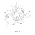
- a dual-bearing reel of a first exemplary embodiment of the present invention is a round dual-bearing reel for bait casting.
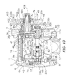
- the dual-bearing reel includes a reel unit 1, a handle 2, a star drag 3 and a spool 12.
- the handle 2 is disposed lateral to the reel unit 1 for rotating the spool 12.
- the star drag 3 is a drag regulation member disposed on the opposite side of the reel unit 1 through the handle 2.
- the spool 12 is rotatably supported by the reel unit 1.
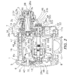
- the handle 2 is of a double-handle type including a plate-shaped handle arm 2a and knobs 2b rotatably attached to the both longitudinal ends of the handle arm 2a. As illustrated in FIG. 2 , the handle arm 2a is disposed on the outer peripheral side of a handle shaft 30 while being disposed closer to the reel unit 1. The handle shaft 30 is herein rotatably attached to the reel unit 1.
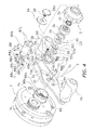
- the handle arm 2a is made of, for instance, light alloy (either aluminum alloy or magnesium alloy). In the first exemplary embodiment, the handle arm 2a is made of aluminum alloy. As illustrated in FIG. 2 , the handle arm 2a is a roughly plate-shaped member including a first surface 2c, a second surface 2d, and a through hole 2e ( FIG. 3 ). The first surface 2c is herein disposed closer to the reel unit 1, whereas the second surface 2d is disposed away from the reel unit 1. As illustrated in FIG. 4 , the handle arm 2a further includes a pair of first engaged recesses 14a and a pair of screw penetrating apertures 14b. The first engaged recesses 14a are outwardly recessed from the inner periphery of the through hole 2e.
- the screw penetrating apertures 14b are positioned radial outwards of the through hole 2e.
- the through hole 2e is positioned in the longitudinal center of the handle arm 2a.
- the handle arm 2a is tapered from the longitudinal center thereof to the longitudinal ends thereof.
- Each first engaged recess 14a is recessed radial outwards from the inner peripheral surface of the through hole 2e in a direction perpendicular to the longitudinal direction of the handle arm 2a.
- the screw penetrating apertures 14b are aligned in the longitudinal direction of the handle arm 2a while interposing the through hole 2e therebetween.
- Each screw penetrating aperture 14b includes a head accommodating portion 14c on the second surface 2d.
- Each head accommodating portion 14c is recessed in a cone shape for accommodating a head portion 15a of a screw member 15 to be described.
- the knobs 2b are rotatably supported by the both tapered longitudinal ends of the handle arm 2a.
- the reel unit 1 is a member made of metal such as aluminum alloy or magnesium alloy. In the first exemplary embodiment, the reel unit 1 is made of aluminum alloy. As illustrated in FIGS. 1 and 2 , the reel unit 1 includes a frame 5, a first side cover 6, and a second side cover 7. The first and second side covers 6 and 7 are attached to the both lateral sides of the frame 5.
- the spool 12 for winding a fishing line is rotatably attached to the inside of the reel unit 1 through a spool shaft 20 (see FIG. 2 ). From the outside in the axial direction of the spool shaft 20, the first side cover 6 has a circular shape whereas the second side cover 7 has a shape formed by a pair of intersecting circles.
- the first side cover 6 is attached to the frame 5 while being openable and closable.
- the first side cover 6 is supported by the frame 5 and pivotable after being axially separated outwards from the frame 5 when being openable and closable.
- the first side cover 6 is openable (or closale) in conjunction with detachment (or attachment) of a screw member (not illustrated in the figures) provided for the second side cover 7.
- the first side cover 6 includes a circular opening 6a for allowing a regulation knob 43 described below to be disposed therein.
- the second side cover 7 is fixed to the frame 5 by screws.
- the second side cover 7 includes a first boss 7a for supporting the handle shaft 30 in a rotatable state. Further, the second side cover 7 includes a second boss 7b for supporting the spool shaft 20 in a rotatable state.
- the second boss 7b is disposed away from the first boss 7a at a predetermined distance.
- the frame 5 includes a first side plate 8, a second side plate 9, a top coupling portion 10a, and a pair of bottom coupling portions 10b.
- the first and second side plates 8 and 9 are configured opposite to each other at a predetermined distance.
- the first and second side plates 8 and 9 are integrally coupled by the top and bottom coupling portions 10a and 10b.
- the first side plate 8 includes a stepped circular opening 8a (see FIG. 2 ) positioned slightly higher than the center part thereof.
- a spool support portion 13, which forms a part of the reel unit 1, is screwed into the opening 8a.
- a brake mechanism 25 is disposed between the spool support portion 13 and the spool 12 for braking the spool 12 in casting.
- the top coupling portion 10a is disposed on a plane including the outer peripheries of the first and second side plates 8 and 9.
- the bottom coupling portions 10b are aligned back and forth while being disposed inwards of the outer peripheries of the first and second side plates 8 and 9.
- a fishing-rod attachment leg 44 is fixed to the bottom coupling portions 10b by rivets.
- the fishing-rod attachment leg 44 is a member elongated back and forth for attaching the reel onto the fishing rod.
- the fishing-rod attachment leg 44 is made of metal such as aluminum alloy.
- the frame 5 accommodates the spool 12, a clutch lever 17 and, a level winding mechanism 18.
- the clutch lever 17 functions as a thumb pad in thumbing the fishing line.
- the level winding mechanism 18 is configured to uniformly wind the fishing line onto the spool 12.
- a rotation transmission mechanism 19 a clutch mechanism 21, a clutch control mechanism 22, a drag mechanism 23 and, a casting control mechanism 24 are disposed in the space between the frame 5 and the second side cover 7.
- the rotation transmission mechanism 19 is configured to transmit rotational force from the handle 2 to the spool 12 and the level winding mechanism 18.
- the clutch mechanism 21 is configured to couple/decouple the handle 2 and the spool 12.
- the clutch control mechanism 22 is configured to control and set the clutch mechanism 21 to be in either a clutch-on state (i.e., a coupled state) or a clutch-off state (i.e., a decoupled state) in response to an operation of the clutch lever 17.
- a clutch-on state i.e., a coupled state
- a clutch-off state i.e., a decoupled state
- the drag mechanism 23 is configured to brake rotation of the spool 12 in the fishing-line releasing direction.
- the casting control mechanism 24 is configured to regulate resistance produced in rotation of the spool 12.
- the spool 12 includes a pair of flanges 12a and a bobbin trunk 12b.
- the flanges 12a are saucer-shaped portions formed on the both axial ends of the spool 12.
- the bobbin trunk 12b is a tubular portion formed between the flanges 12a.
- the outer peripheral surface of the left flange 12a (see FIG. 2 ) is disposed away from the inner peripheral side of the opening 8a through a slight clearance for preventing the fishing line from being stuck.
- the spool 12 is non-rotatably fixed to the spool shaft 20 penetrating through the inner peripheral side of the bobbin trunk 12b by, for instance, serration coupling.
- the method of fixing the spool 12 to the spool shaft 20 is not herein limited to serration coupling.
- a variety of coupling methods e.g., key coupling or spline coupling may be used for coupling the spool 12 to the spool shaft 20.
- the spool shaft 20 is disposed in parallel to the handle shaft 30.
- the spool shaft 20 is made of non-magnetic metal such as SUS304.
- the spool shaft 20 is extended outwards of the second side cover 7 while penetrating the second side plate 9.
- the extended end of the spool shaft 20 is rotatably supported by the second boss 7b through a first bearing 26a.
- the second boss 7b is attached to the second side cover 7 while protruding outwards.
- the other end of the spool shaft 20 is rotatably supported by a second bearing 26b.
- the spool shaft 20 includes a large-diameter portion 20a, a first small-diameter portion 20b, and a second small-diameter portion 20c.
- the large-diameter portion 20a is positioned in the axial center part of the spool shaft 20.
- the first and second small-diameter portions 20b and 20c are formed on the both axial ends of the spool shaft 20.
- the first small-diameter portion 20b is supported by the first bearing 26a, whereas the second small-diameter portion 20c is supported by the second bearing 26b.
- magnets 62 of the brake mechanism 25 are attached onto a portion of the spool shaft 20 positioned between the second small-diameter portion 20c (the left-side one in FIG. 2 ) and the large-diameter portion 20a.
- the portion of the spool shaft 20, which attaches the magnets 62 thereon, has an outer diameter greater than that of the second small-diameter portion 20c but less than that of the large-diameter portion 20a.
- the right end of the large-diameter portion 20a of the spool shaft 20 is disposed in a position where the spool shaft 20 penetrates the second side plate 9.
- An engaging pin 29, which forms a part of the clutch mechanism 21, is fixed to the right end of the large-diameter portion 20a. Specifically, the engaging pin 29 penetrates the large-diameter portion 20a along the diameter of the large-diameter portion 20a. The both ends of the engaging pin 29 are radially protruding from the large-diameter
- the rotation transmission mechanism 19 includes the handle shaft 30, a drive gear 31, a pinion gear 32, a first gear member 36a ( FIG. 2 ), and a second gear member 36b.
- the drive gear 31 is fixed onto the handle shaft 30.
- the pinion gear 32 is a tubular member to be meshed with the drive gear 31.
- the handle shaft 30 is rotatably attached to the second side plate 9 and the second side cover 7 through a bearing 16 and a one-way clutch 86, respectively.
- the handle shaft 30 is prevented from rotating in the fishing-line releasing direction (i.e., prevented from reversely rotating) by the roller-type one-way clutch 86.
- the handle shaft 30 includes a rotational coupling portion 30a on the outer peripheral surface thereof.
- the rotational coupling portion 30a is coupled to a drag washer 51 to be described in a unitarily rotatable state.
- the rotational coupling portion 30a is formed by a pair of parallel flat surfaces formed on the outer peripheral surface of the handle shaft 30.
- the handle shaft 30 includes a male threaded portion 30b on the tip thereof. A nut portion 3b of the star drag 3 to be described is screwed onto the male threaded portion 30b.
- the handle shaft 30 includes a female threaded hole 30c in one of the distal end surfaces thereof.
- the female threaded hole 30c is formed in the center of the distal end surface of the handle shaft 30.
- the handle shaft 30 includes an engaging portion 30d with a small diameter on the outer peripheral surface of the distal end thereof.
- the engaging portion 30d has a shape roughly similar to but smaller than that of the rotational coupling portion 30a.
- the one-way clutch 86 is attached radially between the second side cover 7 and the handle shaft 30.
- the one-way clutch 86 includes an outer race 86a, an inner race 86b and a rocking element 86c.
- the outer race 86 is made of iron-based alloy including stainless alloy, such as SUS440C.
- the outer race 86a is attached onto the first boss 7a in a non-rotatable state.
- the first boss 7a is herein attached to the second side cover 7 while being protruding outwards.
- the inner race 86b is made of iron-based alloy including stainless alloy, such as SUS 440C.
- the inner race 86b is rotatably attached onto the handle shaft 30.
- the rollers 86c are made of iron-based alloy including stainless alloy, such as SUS440C.
- the rollers 86c forming a cylindrical roller unit, are disposed between the outer race 86a and the inner race 86b while being allowed to get stuck therebetween. Anticorrosive performance is enhanced for the surfaces of these members by reformation.
- the inner race may be attached onto the handle shaft 30 in a unitarily rotatable state.
- a retainer section 4 is disposed axially between the inner race 86b and the handle arm 2a for preventing the inner race 86b from being detached from the handle arm 2a.
- the retainer section 4 is fixed to the first surface 2c of the handle arm 2a.
- the retainer section 4 includes a restricting member 88 for restricting movement of the inner race 86b in the axial direction of the handle shaft 30.
- the inner race 86b is interposed between the handle 2 and the drag washer 51 to be described of the drag mechanism 23 while making contact with both of the handle 2 and the drag washer 51.
- the inner race 86b is prevented from being detached from the first surface 2c of the handle arm 2a by the restricting member 88. Accordingly, the inner race 86b is restricted from moving in the axial direction of the handle shaft 30.
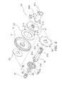
- the inner race 86b includes a tubular portion 87a disposed on the outer peripheral side of the handle shaft 30, a retainer protrusion 87b, a pair of first engaging protrusions 87c, and a pair of second engaging protrusions 87d.
- the retainer protrusion 87b is annularly protruding from the outer peripheral surface of a first end (i.e., a right end in FIG. 3 ) of the tubular portion 87a.
- the end surface of the retainer protrusion 87b makes contact with the first surface 2c of the handle arm 2a.
- the first engaging protrusions 87c are axially protruding towards the handle arm 2a from the axial end of the retainer protrusion 87b.
- the first engaging protrusions 87c are engaged with the first engaged recesses 14a of the handle arm 2a. Accordingly, the inner race 86b and the handle arm 2a are coupled in a unitarily rotatable state.
- the second engaging protrusions 87d are axially protruding towards the drag washer 51 from a second end (i.e., a left end in FIG. 3 ) of the tubular portion 87a.
- the second engaging protrusions 87d are engaged with the drag washer 51 in a unitarily rotatable state.
- the phase of the second engaging protrusions 87d is shifted from that of the first engaging protrusions 87c by an angle of 90 degrees.
- the phase of the second engaging protrusions 87d may be identical to that of the first engaging protrusions 87c.
- the phase of the second engaging protrusions 87d may be shifted from that of the first engaging protrusions 87c by any suitable angle excluding 90 degrees.
- the drag washer 51 is engaged with the handle shaft 30 in a unitarily rotatable state. Therefore, the inner race 86b is coupled to the handle shaft 30 through the drag washer 51 in a unitarily rotatable state. Further, the inner race 86b and the handle arm 2a are directly coupled in a unitarily rotatable state.
- the restricting member 88 is made of, for instance, aluminum alloy. As illustrated in FIGS. 3 and 4 , the restricting member 88 is fixed to the first surface 2c of the handle arm 2a by the screw members 15 for restricting movement of the inner race 86b in the axial direction of the handle shaft 30.
- the screw members 15 are herein inserted from the second surface 2d (i.e., the outer surface) of the handle arm 2a.
- the restricting member 88 includes a restricting portion 88b, a through hole 88c and a pair of fixed portions 88d.
- the restricting portion 88b includes a retainer surface 88a making contact with a surface of the retainer protrusion 87b, i.e., a surface opposite to the axially outward end surface of the retainer protrusion 87b.
- the through hole 88c allows the tubular portion 87a to pass therethrough.
- the fixed portions 88d are fixed to the handle arm 2a.
- the restricting portion 88b includes an annular end surface 88e contactable with the first surface 2c of the handle arm 2a.
- the retainer surface 88a is annularly recessed on the inner peripheral side of the end surface 88e for accommodating the retainer protrusion 87b of the inner race 86b.
- the depth from the end surface 88e to the retainer surface 88a is equal to or slightly less than the thickness of the retainer protrusion 87b.
- the through hole 88c is formed in the inner peripheral surface of the restricting portion 88b.
- Each fixed portion 88d is longitudinally tapered along the outer periphery of the restricting portion 88b.
- Each fixed portion 88d includes a female threaded portion 88f that the screw member 15 is screwed.
- the female threaded portions 88f are configured to be opposite to the screw penetrating apertures 14b.
- the drive gear 31 is rotatably attached onto the handle shaft 30 while being frictionally connected to the handle shaft 30 through the drag mechanism 23.
- the pinion gear 32 is a tubular member that the spool shaft 20 penetrates through the center part thereof.
- the pinion gear 32 is inwardly extended from the outside of the second side plate 9.
- the pinion gear 32 is attached onto the spool shaft 20 while being axially movable. Further, the left end (see FIG. 2 ) of the pinion gear 32 is supported by the second side plate 9 through a bearing 33 while being rotatable and axially movable.
- the pinion gear 32 includes an engaged groove 32a on the left end thereof (see FIG. 2 ).
- the engaged groove 32a is engaged with the engaging pin 29.
- the engaged groove 32a and the engaging pin 29 form the clutch mechanism 21.
- the pinion gear 32 includes a narrowed portion 32b in the axial intermediate part thereof.
- the pinion gear 32 includes a gear portion 32c on the axial right end thereof.
- the gear portion 32c is meshed with the drive gear 31.
- the drag mechanism 23 is configured to regulate drag force in response to an operating position of the star drag 3 attached onto the handle shaft 30.
- the drag mechanism 23 is allowed to regulate and brake rotation of the spool 12 in the fishing-line releasing direction.
- the star drag 3 is attached onto the tip of the handle shaft 30 while interposing the handle 2 together with the inner race 86b.
- the star drag 3 includes an operating part body 3a and the nut portion 3b.
- the operating part body 3a includes convexo-concaves on the outer peripheral surface thereof.
- the nut portion 3b is attached to the operating part body 3a while being unitarily rotatable therewith and axially movable. As described above, the nut portion 3b is screwed onto the male threaded portion 30b. When the operating part body 3a is rotated, the nut portion 3b is movable in the axial direction of the handle shaft 30.
- a coil spring 3c is disposed in a compressed state between the nut portion 3b and the operating part body 3a.
- the coil spring 3c is an urging member for urging the operating part body 3a towards the distal end of the handle shaft 30.
- the operating part body 3a is prevented from being detached from the handle shaft 30 by a fixation bolt 28.
- the fixation bolt 28 is screwed into the female threaded hole 30c formed in the distal end surface of the handle shaft 30.
- the fixation bolt 28 includes a head 28a having an outer diameter greater than that of the distal end of the handle shaft 30.
- the fixation bolt 28 prevents the handle 2 from being detached from the handle shaft 30 through the star drag 3.
- a first washer member 34 is attached axially between the operating part body 3a and the fixation bolt 28.
- the first washer member 34 is attached onto the small-diameter engaging portion 30d formed on the distal end of the handle shaft 30 while being unitarily rotatable therewith.
- the operating part body 3a constantly makes contact with the first washer member 34 while being pressed by the coil spring 3c.
- a second washer member 39 In addition to the nut portion 3b, a second washer member 39, a pair of disc springs 50 and a star drag sound producing mechanism 54 are disposed in the operating part body 3a.
- the second washer member 39 makes contact with the nut portion 3b.
- the disc springs 50 form a part of the drag mechanism 23.
- the second washer member 39 and the disc springs 50 are disposed in the inside of the operating part body 3a.
- the second washer member 39 is disposed for efficiently transmitting pressure of the nut portion 3b to the disc springs 50.
- the star drag sound producing mechanism 54 is configured to produce sounds in accordance with a rotational operation of the star drag 3.
- the star drag sound producing mechanism 54 is disposed between the handle 2 and the star drag 3.
- the star drag sound producing mechanism 54 is disposed between the disc springs 50 and the handle arm 2a.
- the star drag sound producing mechanism 54 includes a transmission washer 55, a sound producing member 56, and a hitting member 57.
- the transmission washer 55 is coupled to the rotational coupling portion 30a of the handle shaft 30 in a unitarily rotatable state.
- the transmission washer 55 is configured to transmit spring force of the disc springs 50 to the handle arm 2a while making contact with the disc spring 50.
- the transmission washer 55 includes a non-circular outer peripheral surface 55a and a non-circular inner peripheral surface 55b to be engaged with the engaging portion 30d.
- the sound producing member 56 is attached to the outer peripheral surface 55a of the transmission washer 55.
- the sound producing member 56 is thus engaged with the transmission washer 55 in a unitarily rotatable state.
- the sound producing member 56 is an annular plate-shaped member.
- the sound producing member 56 includes sound producing recesses 56a on a surface thereof disposed closer to the star drag 3.
- the sound producing recesses 56a are circumferentially aligned at predetermined intervals.
- the sound producing member 56 includes an engaging hole 56b in the inner peripheral surface thereof.
- the engaging hole 56b is a non-circular hole to be engaged with the non-circular outer peripheral surface 55a of the transmission washer 55.
- the hitting member 57 is configured to repeatedly hit the sound producing recesses 56a of the sound producing member 56.
- the hitting member 57 is attached to an attachment recess 3e formed on an end surface of the operating part body 3a (i.e., the end surface closer to the handle 2) while being allowed to be protruding from and retracted to the attachment recess 3e.
- the hitting member 57 is urged towards the sound producing member 56 by a coil spring 58 accommodated in the attachment recess 3e.
- the drag mechanism 23 is disposed about the handle shaft 30. As illustrated in FIGS. 3 , 4 and 5 , the drag mechanism 23 includes the aforementioned two disc springs 50, the drag washer 51, a first drag disc 52 and a second drag disc 53.
- the disc springs 50 are pressed by the nut portion 3b of the star drag 3.
- the first and second drag discs 52 and 53 are disposed while interposing the drive gear 31 therebetween.
- the disc springs 50 are disposed for minutely adjusting pressure by the nut portion 3b. Specifically, the disc springs 50 are disposed between the star drag 3 and the handle 2.
- the disc springs 50 are configured to transmit spring force varying in conjunction with the axial movement of the star drag 3 to the drag washer 51 through the handle 2 and the inner race 86b.
- the disc springs 50 are also disposed for preventing the handle arm 2a from wobbling when the star drag 3 is loosened for moving the operating part body 3a towards the distal end of the handle shaft 30. Therefore, each disc spring 50 is disposed in a more compressed state than in its free state even when the star drag 3 is operated for producing the weakest drag force (i.e., the most compressed state of the coil spring 3c) as illustrated in a part of FIG. 3 above a handle axis X. It should be noted that a part of FIG. 3 below the handle axis X illustrates the disc springs 50 and their periphery under the strongest drag force.
- the drag washer 51 is coupled to the handle shaft 30 in a unitarily rotatable state.
- the drag washer 51 is coupled to the inner race 86b as well as the handle shaft 30 in a unitarily rotatable state.
- the drag washer 51 includes a first coupling portion 51 a and a second coupling portion 51 b.
- the first coupling portion 51 a is coupled to the handle shaft 30 in a unitarily rotatable state
- the second coupling portion 51 b is coupled to the inner race 86b in a unitarily rotatable state.
- the drag washer 51 includes the first coupling portion 51 a in the inner periphery thereof.
- the first coupling portion 51 a includes a pair of straight portions 51 c and a pair of connecting portions 51 d.
- the straight portions 51 c are disposed in parallel to each other.
- One connecting portion 51 d connects one ends of the straight portions 51 c, whereas the other connection portion 51 d connects the other ends of the straight portions 51 c.
- the straight portions 51 c are engaged with the surfaces of the rotational coupling portion 30a of the handle shaft 30 and rotation of the drag washer 51 is thereby transmitted to the handle shaft 30.
- the second coupling portion 51 b includes a pair of second engaged recesses 51 e recessed on the connecting portions 51 d.
- the second engaging protrusions 87d of the inner race 86b are engaged with the second engaged recesses 51 e, and rotation of the inner race 86b is thereby transmitted to the drag washer 51. Further, rotation of the drag washer 51 is transmitted to the handle shaft 30. The handle shaft 30 is thus rotated by rotation of the handle 2.
- rotation of the handle has been configured to be directly transmitted to the handle shaft.
- rotation of the handle 2 is directly transmitted to the inner race 86b and is further transmitted to the handle shaft 30 through the inner race 86b and the drag washer 51.
- the inner race 86b is herein coupled to the handle shaft 30 through the drag washer 51 in a unitarily rotatable state.
- the first drag disc 52 makes contact with the drive gear 31 and the drag washer 51 while being interposed therebetween.
- the second drag disc 53 makes contact with the drive gear 31 and a ratchet wheel 38 while being interposed therebetween.
- the first and second drag discs 52 and 53 are rotatable with respect to the handle shaft 30.
- the ratchet wheel 38 also functions as the drag mechanism 23.
- the ratchet wheel 38 is positioned to make contact with a large-diameter flanged portion 30e formed on the outer peripheral surface of the handle shaft 30.
- the ratchet wheel 38 receives pressure of the star drag 3 through the flanged portion 30e.
- the clutch lever 17 is disposed on the rear part of the interposed space between the first side plate 8 and the second side plate 9. Simultaneously, the clutch lever 17 is disposed rearwards of the spool 12.
- the clutch lever 17 is configured to slide up and down between the first side plate 8 and the second side plate 9.
- the clutch lever 17 includes an engaging shaft 17a on the same side as the handle 2.
- the engaging shaft 17a is integrally formed with the clutch lever 17.
- the engaging shaft 17a penetrates through the second side plate 9. Further, the engaging shaft 17a is engaged with the clutch control mechanism 22.
- the level winding mechanism 18 is disposed forwards of the spool 12 while being disposed between the first side plate 8 and the second side plate 9.
- the level winding mechanism 18 includes a helical shaft 46 and a fishing-line guide portion 47.
- the helical shaft 46 includes intersecting helical grooves 46a on the outer peripheral surface thereof.
- the fishing-line guide portion 47 is configured to reciprocate along the axial direction of the spool shaft 20 in conjunction with rotation of the helical shaft 46 in order to guide the fishing line.
- the first gear member 36a forming a part of the rotation transmission mechanism 19, is attached onto the right end of the helical shaft 46 (see FIG. 2 ).
- the first gear member 36a is meshed with the second gear member 36b attached onto the handle shaft 30 in a unitarily rotatable state.
- the helical shaft 46 is configured to be rotated in conjunction with rotation of the handle shaft 30 in the fishing line-winding direction.
- the fishing-line guide portion 47 is configured to reciprocate along the axial direction of the spool shaft 20.
- the clutch control mechanism 22 includes a clutch yoke 35.
- the clutch yoke 35 is engaged with the narrowed portion 32b of the pinion gear 32 for moving the pinion gear 32 along the axial direction of the spool shaft 20.
- the clutch yoke 35 is configured to be moved in response to a slide position of the clutch lever 17 between a clutch-on position and a clutch-off position that is arranged outwards of the clutch-on position in the axial direction of the spool shaft 20.
- the casting control mechanism 24 includes a plurality of friction plates 48 and a brake cap 49.
- the friction plates 48 are abutted to the both axial ends of the spool shaft 20 from the axial outside of the spool shaft 20.
- the brake cap 49 is configured to regulate abutting pressure of the friction plates 48 against the spool shaft 20.
- the left-side friction plate 48 is attached within the spool support portion 13.
- the brake cap 49 is screwed onto the outer peripheral surface of the second boss 7b of the second side cover 7.
- the brake mechanism 25 includes a spool brake unit 40, a rotation speed sensor (not illustrated in the figures), the regulation knob 43 and a spool control unit (not illustrated in the figure).
- the spool brake unit 40 is mounted on both the spool 12 and the reel unit 1.
- the spool control unit 40 is a microcomputer configured to electrically control the spool brake unit 40 in response to an operational position of the regulation knob 43.
- the spool brake unit 40 is an electrically controllable unit configured to brake the spool 12 by power generation.
- the spool brake unit 40 includes a rotor 61, a plurality of (e.g., four) coils 63 and a switching element (not illustrated in the figures).
- the rotor 61 includes four magnets 62 aligned along the rotational direction of the spool shaft 20.
- the coils 63 are serially connected and configured opposite to each other on the outer peripheral side of the rotor 61.
- the switching element is connected to the both ends of the serially-connected coils 63.
- the rotation speed sensor is disposed for detecting the rotational speed of the spool 12 and computing tension based on the detected rotational speed.
- the spool control unit is embedded with a circuit board 70 fixed to the spool support portion 13.
- the regulation knob 43 is rotatably attached to the spool support portion 13.
- the clutch lever 17 In fishing, the clutch lever 17 is firstly slid and set in the clutch off position for setting the clutch mechanism 21 in the clutch off state.
- the fishing rod is cast under the condition for releasing the fishing line from the spool 12.
- a clutch return mechanism (not illustrated in the figures) is accordingly activated and the clutch mechanism 21 is set in the clutch on state.
- the clutch lever 17 is also herein returned to the clutch on position.
- an angler waits for a fish to be hooked by the terminal tackle.
- the handle 2 is rotated in the fishing-line winding direction for pulling the hooked fish.
- rotation of the handle 2 is transmitted to the inner race 86b and is further transmitted to the handle shaft 30 through the drag washer 51.
- the drive gear 31 frictionally coupled to the handle shaft 30 is rotated by the drag mechanism 23. Rotation of the drive gear 31 is transmitted to the spool shaft 20 through the pinion gear 32 and the clutch mechanism 21. Accordingly, the spool 12 is rotated in the fishing-line winding direction.
- the inner race is affected by looseness (i.e., clearance) between the handle shaft and the drag washer and looseness (i.e., clearance) between the drag washer and the inner race when the drag mechanism 23 is set to have a weak drag force in winding the fishing line.
- looseness i.e., clearance
- looseness i.e., clearance
- clearance looseness between the drag washer and the inner race when the drag mechanism 23 is set to have a weak drag force in winding the fishing line.
- the handle wobbles due to the structure that the handle is slightly rotatable by the clearance in the fishing-line releasing direction.
- rotation of the handle 2 is directly transmitted to the inner race 86b.
- the inner race 86b is coupled to the handle arm 2a in a unitarily rotatable state while axial movement thereof is restricted by the restricting member 88 fixed to the first surface 2c of the handle arm 2a. Therefore, the inner race 86b can be reliably fixed to the handle 2.
- a handle arm 102a of a handle 102 includes a protrusion accommodating portion 114d for accommodating the retainer protrusion 87b of the inner race 86b, as illustrated in FIG. 6 .
- the protrusion accommodating portion 114d is circularly recessed on a first surface 102c of the handle arm 102a while surrounding a through hole 102e.
- the retainer protrusion 87b is accommodated in the protrusion accommodating portion 114d. Therefore, a restricting portion 188b and a pair of fixed portions 188d, included in a restricting member 188 of a retainer section 104, are formed as a plate shaped member.
- the other structures are the same as those of the first exemplary embodiment. Therefore, explanation thereof will be hereinafter omitted.
- the handle arm 102a and the star drag 3 can be disposed closer to the reel unit 1 by the depth of the protrusion accommodating portion 114d. Further, the restricting member 188 is not required to accommodate the retainer protrusion 87b. Therefore, the restricting member 188 can be simply formed.
- screw members 215 are inserted into corresponding components from a first surface 202c side of a handle arm 202a, as illustrated in FIG. 7 . Therefore, a pair of fixed portions 288d of a restricting member 288 of a retainer section 204 includes screw penetrating apertures 288g, instead of female threaded portions, in the same positions as the female threaded portions 88f of the first exemplary embodiment.
- the handle arm 202a of the handle 202 includes female threaded portions 214e in the same positions as the screw penetrating apertures 14b of the first exemplary embodiment. The female threaded portions 214e allow the screw member 215 to be screwed therein.
- the other structures are the same as those of the first exemplary embodiment. Therefore, explanation thereof will be hereinafter omitted.
- the restricting member 288 is fixed to the handle arm 202a by the screw members 215 inserted therein from the first surface 202c side. Therefore, the heads of the screw members 215 are not exposed to a second surface 202d side.
- a restricting member 388 of a retainer section 304 is deformed to a handle arm 302a of a handle 302 without using screw members, as illustrated in FIG. 8 .
- the handle arm 302a include a pair of fix recesses 314f disposed perpendicular to a pair of first engaged recesses 314a in a through hole 302e.
- the first engaged recesses 314a are herein separated away from each other in the longitudinal direction of the handle arm 302a not in a perpendicular direction to the longitudinal direction of the handle arm 302a.
- the fix recesses 314f are disposed perpendicularly to the longitudinal direction of the handle arm 302a.
- An inner race 386b includes a pair of first engaging protrusions 387c disposed perpendicularly to the first engaging protrusions 87c of the first exemplary embodiment.
- the restricting member 388 is made of aluminum alloy.
- the restricting member 388 includes a restricting portion 388b, a through hole 388c and a fixed portion 388d.
- the restricting portion 388b includes a retainer surface 388a making contact with a surface of a retainer protrusion 387b of the inner race 386b, i.e., a surface opposite to the axially outward end surface of the retainer protrusion 387b.
- the through hole 388c allows a tubular portion 387a of the inner race 386b to pass therethrough.
- the fixed portion 388d is fixed to the handle arm 302a.
- the fixed portion 388d includes a pair of fix protrusions 388g to be deformed to the handle arm 302a.
- the fix protrusions 388g are protruding from the end surface of the restricting portion 388b towards the handle arm 302a.
- the inner peripheral part of each fix protrusion 388g is chamfered in a tapered shape for easily deforming each fix protrusion 388g towards the outer peripheral side in deforming.
- the protruding length of each fix protrusion 388g is slightly longer than the thickness of the handle arm 302a. Therefore, the tips of the fix protrusions 388g are protruding out of the second surface 302d of the handle arm 302a.
- the tips of the fix protrusions 388g are radial-outwardly pressed on the second surface 302d of the handle arm 302a by an arbitrary suitable deforming tool.
- the restricting member 388 is thus deformed to the handle arm 302a.
- the inner race 386b is coupled to the handle arm 302a in a unitarily rotatable state while being restricted from axially moving.
- the other structures are the same as those of the first exemplary embodiment. Therefore, explanation thereof will be hereinafter omitted.
- the restricting member 388 is made of easily deformable metal such as aluminum. Therefore, the restricting member 388 can be fixed to the handle arm 302a by deforming without using an additional member for fixation.
- a dual-bearing reel according to a second exemplary embodiment of the present invention is a round dual-bearing reel for bait-casting.
- a handle 402, a star drag 403, a one-way clutch 486 and a rotation transmission mechanism 419 are only differently structured from the corresponding components in the dual-bearing reel of the first exemplary embodiment. Therefore, detailed explanation of the other components will be hereinafter omitted.
- a reference numeral, assigned to a component of the first exemplary embodiment will be also assigned to a component of the second exemplary embodiment if these components are the same.
- the dual-bearing reel includes the reel unit 1, the handle 402, the star drag 403 and the spool 12.
- the handle 402 is disposed lateral to the reel unit 1 for rotating the spool 12.
- the star drag 403 is a drag regulation member disposed on the opposite side of the reel unit 1 through the handle 402.
- the spool 12 is rotatably supported by the reel unit 1.
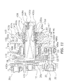
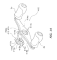
- the handle 402 is of a double-handle type including a plate-shaped handle arm 402a and the knobs 2b rotatably attached to the both longitudinal ends of the handle arm 402a. As illustrated in FIG. 10 , the handle arm 402a is disposed on the outer peripheral side of a handle shaft 430 while being disposed closer to the reel unit 1. The handle shaft 430 is herein rotatably attached to the reel unit 1.
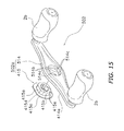
- the handle arm 402a includes a handle body 414 and an inserted member 415 fixed to the handle body 414.
- the handle body 414 is made of, for instance, light alloy (either aluminum alloy or magnesium alloy). In the present exemplary embodiment, the handle body 414 is made of aluminum alloy.
- the handle body 414 includes a non-circular hole 414a on the center part thereof (i.e., a penetrating part allowing the handle shaft 430 to penetrate therethrough).
- the knobs 2 are rotatably supported by the both longitudinal ends of the handle body 414. As illustrated in FIG.
- the non-circular hole 414a of the handle body 414 is a roughly oval hole formed by a pair of opposed straight portions 414b and a pair of circular arc portions 414c.
- One circular arc portion 414c connects one ends of the linear portions 414b while the other circular arc portion 414c connects the other ends of the linear portion2 414b.
- the inserted member 415 is made of, for instance, metal such as brass or zinc alloy.
- the inserted member 415 is disposed for preventing the handle body 414 and an inner race 486b of the one-way clutch 486 to be described from suffering from galvanic corrosion.
- the inserted member 415 includes a tubular portion 415b and a flanged portion 415c.
- the tubular portion 415b includes an outline portion 415a having a non-circular outline.
- the outline portion 415a is engaged with the non-circular hole 414a of the handle body 414 in a unitarily rotatable state.
- the flanged portion 415c has a diameter greater than that of the tubular portion 415b.
- the tubular portion 415b includes a through hole 415d and a pair of first engaged recesses 415e on the inner peripheral surface thereof.
- the through hole 415d is disposed onto the outer peripheral surface of the handle shaft 430 for allowing the tubular portion 415 to be rotatably supported thereon.
- the first engaged recesses 415e are coupled to the inner race 486b for allowing the tubular portion 415d to unitarily rotate therewith.
- the first engaged recesses 415e are formed on the diameter of the through hole 415d.
- the axial length of the tubular portion 415b is greater than the thickness of the handle body 414.
- the tubular portion 415b is protruding from a first surface 414d (i.e., a surface disposed away from the reel unit 1) of the handle body 414.
- the protruding end of the tubular portion 415d is deformed by an arbitrary suitable deforming tool. Accordingly, the inserted member 415 is deformed and fixed to the handle body 414 in a unitarily rotatable state.
- the flanged portion 415c is abutted to a second surface 414e (i.e., a surface disposed closer to the reel unit 1) of the handle body 414.
- the flanged portion 415c is allowed to press the inner race 486b while making contact with the end surface of the inner race 486b.
- the reel unit 1 is a member made of metal such as aluminum alloy or magnesium alloy.
- the reel unit 1 includes the frame 5, the first side cover 6 and the second side cover 7.
- the first and second side covers 6 and 7 are attached to the both lateral sides of the frame 5.
- the spool 12 for winding a fishing line is rotatably attached to the inside of the reel unit 1 through the spool shaft 20 (see FIG. 2 ).
- the frame 5 accommodates the spool 12, the clutch lever 17 and the level winding mechanism 18.
- the clutch lever 17 functions as a thumb pad in thumbing the fishing line.
- the level winding mechanism 18 is configured to uniformly wind the fishing line onto the spool 12.
- the rotation transmission mechanism 419, the clutch mechanism 21, the clutch control mechanism 22, the drag mechanism 23 and the casting control mechanism 24 are disposed in the space between the frame 5 and the second side cover 7.
- the rotation transmission mechanism 419 includes the handle shaft 430, the drive gear 31, the pinion gear 32, the first gear member 36a and the second gear member 36b.
- the drive gear 31 is fixed onto the handle shaft 430.
- the pinion gear 32 is a tubular member meshed with the drive gear 31.
- the handle shaft 430 is rotatably attached to the second side plate 9 and the second side cover 7 through the bearing 16 and the one-way clutch 486, respectively.
- the handle shaft 430 is prevented from rotating in the fishing-line releasing direction (i.e., prevented from reversely rotating) by the roller-type one-way clutch 486.
- the handle shaft 430 includes a rotational coupling portion 430a on the outer peripheral surface thereof.
- the rotational coupling portion 430a is coupled to the drag washer 51 to be described in a unitarily rotatable state.
- the rotational coupling portion 430a is formed by a pair of parallel flat surfaces formed on the outer peripheral surface of the handle shaft 430.
- the handle shaft 430 includes a first male threaded portion 430b on the tip thereof. A nut member 428 to be described is screwed onto the first male threaded portion 430b.
- the handle shaft 430 further includes a second male threaded portion 430c on the outer peripheral surface thereof.
- the second male threaded portion 430c is disposed adjacent to the first male threaded portion 430b, while being disposed closer to the base end of the handle shaft 430 than the first male threaded portion 430b is.
- a nut portion 403c of the star drag 403 to be described is screwed onto the second male threaded portion 430c.
- the second male threaded portion 430c has a diameter greater than that of the first male threaded portion 430b.
- the handle shaft 430 includes a female threaded portion 430d on the axial end surface thereof. The female threaded portion 430d is displaced from the center on the axial end surface of the handle shaft 430.
- the one-way clutch 486 is attached radially between the second side cover 7 and the handle shaft 430.
- the one-way clutch 486 includes an outer race 486a, the inner race 486b and rollers 486c.
- the outer race 486a is made of iron-related alloy including stainless alloy, such as SUS440C.
- the outer race 486a is attached onto the first boss 7a in a non-rotatable state.
- the first boss 7a is herein attached to the second side cover 7 while being protruding outwards.
- the inner race 486b is made of iron-related alloy including stainless alloy, such as SUS404C.
- the inner race 486b is rotatably attached to the handle shaft 430.
- the rollers 486c are made of iron-related alloy including stainless alloy, such as SUS440C.
- the rollers 486c which forms a cylindrical roller unit, are disposed between the outer race 486a and the inner race 486b while being allowed to get stuck therebetween. Anticorrosive performance is enhanced for the surfaces of these members by reformation.
- the inner race 486b is interposed between the handle 402 (specifically, the inserted member 415) and the drag washer 51 to be described of the drag mechanism 23 while making contact with both of the handle 402 and the drag washer 51.
- the inner race 486b includes a pair of first engaging protrusions 486d on a first end (i.e.. a right end in FIG. 11 ) closer to the handle 402.
- the first engaging protrusions 486d are axially protruding and engaged with the first engaged recesses 415e.
- the inner race 486b includes a pair of second engaging protrusions 486e on a second end (i.e., a left end in FIG. 11 ) opposite to the first end.
- the second engaging protrusions 486e are axially protruding and engaged with the drag washer 51 in a unitarily rotatable state.
- the drag washer 51 is engaged with the handle shaft 430 in a unitarily rotatable state. Therefore, the inner race 486b is coupled to the handle shaft 430 through the drag washer 51 in a unitarily rotatable state.
- the inner race 486b and the handle 402 are directly coupled in a unitarily rotatable state. In the present exemplary embodiment, however, the inner race 486b is not prevented from being detached from the handle 402.
- the first engaging protrusions 486d may be deformed to the first engaged recesses 415e, for instance, for preventing the inner race 486b from being detached form the handle arm 402a through the first engaging protrusions 486d and the first engaged recesses 415e.
- the retainer section 411 may be formed by the deforming structure.
- the drive gear 31 is rotatably attached onto the handle shaft 430 while being frictionally connected to the handle shaft 430 through the drag mechanism 23.
- the pinion gear 32 is a tubular member that the spool shaft 20 penetrates through the center part thereof.
- the pinion gear 32 is inwardly extended from the outside of the second side plate 9.
- the pinion gear 32 is attached onto the spool shaft 20 while being axially movable. Further, the left end (see FIG. 10 ) of the pinion gear 32 is supported by the second side plate 9 through the bearing 33 while being rotatable and axially movable.
- the pinion gear 32 includes the engaged groove 32a on the left end thereof (see FIG. 10 ).
- the engaged groove 32a is engaged with the engaging pin 29.
- the engaged groove 32a and the engaging pin 29 form the clutch mechanism 21.
- the pinion gear 32 includes the narrowed portion 32b in the axial intermediate part thereof.
- the pinion gear 32 includes the gear portion 32c on the axial right end thereof.
- the gear portion 32c is meshed with the drive gear 31.
- the drag mechanism 23 is configured to regulate drag force in response to an operating position of the star drag 403.
- the drag mechanism 23 is allowed to regulate and brake rotation of the spool 12 in the fishing-line releasing direction.
- the star drag 403 includes an operating part body 403a and the nut portion 403c.
- the operating part body 403a includes a plurality of radially extended operating arms 403b.
- the nut portion 403c is attached to the operating part body 403a while being unitarily rotatable therewith and axially movable. As described above, the nut portion 403c is screwed onto the second male threaded portion 430c. When the operating part body 403a is rotated, the nut portion 403c is movable in the axial direction of the handle shaft 430.
- the star drag 403 is attached onto the tip of the handle shaft 430 while interposing the handle 402 together with the inner race 486b.
- the star drag 403 is prevented from being detached from the handle shaft 430 by the nut member 428 screwed onto the first male threaded portion 430b.
- the nut member 428 prevents the handle 402 from being detached from the handle shaft 430 through the star drag 403.
- the nut member 428 includes a penetrating aperture 428a allowing an anti-rotation screw 441 to axially penetrate therethrough.
- the nut member 428 is prevented from rotating by the anti-rotation screw 441.
- the anti-rotation screw 441 is screwed into the female threaded portion 430d formed on the axial end surface of the handle shaft 430 while penetrating through the penetrating aperture 428a.
- the drag mechanism 23 is disposed about the handle shaft 430. As illustrated in FIGS. 11 , 12 and 13 , the drag mechanism 23 includes a single or plurality of (e.g., two) disc springs 50, the drag washer 51, the first drag disc 52 and the second drag disc 53.
- the disc springs 50 are pressed by the nut portion 403c of the star drag 403.
- the first and second drag discs 52 and 53 are disposed while interposing the drive gear 31 therebetween.
- the disc springs 50 are disposed between the star drag 403 and the handle 402.
- the drag springs 50 are configured to transmit spring force varying in conjunction with the axial movement of the star drag 403 to the drag washer 51 through the handle 402 and the inner race 486b.
- the drag washer 51 is coupled to the handle shaft 430 in a unitarily rotatable state.
- the drag washer 51 is coupled to the handle shaft 430 and the inner race 486b in a unitarily rotatable state. As illustrated in FIG. 13 , the drag washer 51 includes the first coupling portion 51 a and the second coupling portion 51 b. The first coupling portion 51 a is coupled to the handle shaft 430 in a unitarily rotatable state, whereas the second coupling portion 51 b is coupled to the inner race 486b in a unitarily rotatable state. More specifically, the drag washer 51 includes the first coupling portion 51a in the inner periphery thereof. The first coupling portion 51 a includes a pair of the straight portions 51 c and a pair of the connecting portions 51 d. The straight portions 51 c are disposed in parallel to each other.
- One connecting portion 51 d connects one ends of the straight portions 51 c, whereas the other connecting portion 51 d connects the other ends of the straight portions 51 c.
- the straight portions 51 c are engaged with the surfaces of the rotation coupling portion 430a of the handle shaft 430 and rotation of the drag washer 51 is thereby transmitted to the handle shaft 430.
- the second coupling portion 51 b includes a pair of the second engaged recesses 51 e recessed on the connecting portions 51 d.
- the second engaging portions 486e of the inner race 486b are engaged with the second engaged recesses 51 e, and rotation of the inner race 486b is thereby transmitted to the drag washer 51. Further, rotation of the drag washer 51 is transmitted to the handle shaft 430.
- the handle shaft 430 is thus rotated by rotation of the handle 402.
- rotation of the handle has been configured to be directly transmitted to the handle shaft.
- rotation of the handle 402 is directly transmitted to the inner race 486b and is further transmitted to the handle shaft 430 through the inner race 486b and the drag washer 51.
- the first drag disc 52 makes contact with the drive gear 31 and the drag washer 51 while being interposed therebetween.
- the second drag disc 53 makes contact with the drive gear 31 and the ratchet wheel 38 while being interposed therebetween.
- the first and second drag discs 52 and 53 are rotatable with respect to the handle shaft 430.
- the ratchet wheel 38 also functions as the drag mechanism 23.
- the ratchet wheel 38 is disposed to make contact with a large-diameter flanged portion 430e formed on the outer peripheral surface of the handle shaft 430.
- the ratchet wheel 38 receives pressure of the star drag 403 through the flanged portion 430e.
- rotation of the handle 402 is directly transmitted to the inner race 486b in the second exemplary embodiment thus structured. Therefore, looseness between the handle 402 and the inner race 486b is reduced. This prevents the handle 402 from easily rotating in the fishing-line releasing direction and prevents the handle 402 from easily wobbling.
- the handle body 414 is made of iron-related alloy such as stainless alloy.
- the material of the handle body 41 is not limited to the above.
- a reference numeral, assigned to a component of the second exemplary embodiment will be also assigned to a component of a modification 1 of the second exemplary embodiment if these components are the same.
- a reference numeral obtained by adding 100 to that of the corresponding component of the second exemplary embodiment will be given to the component of the modification 1 of the second exemplary embodiment.
- a handle body 514 of a handle arm 502a of a handle 502 is made of carbon fiber reinforced resin.
- the longitudinal center part of the handle body 514 is axial-outwardly bulged compared to the peripheral part thereof for maintaining strength of the handle body 514 made of carbon fiber reinforced resin.
- the handle body 514 When the handle body 514 is sectioned along a perpendicular direction to its longitudinal direction, the center part of the handle body 514 is axial-outwardly protruding compared to the peripheral part thereof.
- the handle body 514 includes a non-circular hole 514a, straight portions 514b and circular arc portions 514c on the center part thereof.
- the handle body 514 thus made of carbon fiber reinforced resin, is prevented from being easily cracked in deforming the inserted member 415 thereto.
- the aforementioned exemplary embodiment can be expressed as follows.
- the reference numeral of the component in the first exemplary embodiment will be used in the following explanation.
- the dual-bearing reel includes the reel unit 1, the handle shaft 30, the one-way clutch 86, the drag mechanism 23, the star drag 3, the handle 2, the spool 12 and the rotation transmission mechanism 19.
- the handle shaft 30 is rotatably supported by the reel unit 1.
- the one-way clutch 86 includes the outer race 86a, the inner race 86b and the rollers 86c.
- the outer race 86a is non-rotatably attached the reel unit 1.
- the inner race 86b is coupled to the handle shaft 30 in a unitarily rotatable state.
- the rollers 86c are disposed between the outer race 86a and the inner race 86b.
- the drag mechanism 23 includes the drag washer 51.
- the drag washer 51 is coupled to the handle shaft 30 in a unitarily rotatable state.
- the star drag 3 is a member attached to the handle shaft 30 for regulating drag force of the drag mechanism 23.
- the handle 2 is disposed between the star drag 3 and the reel unit 1.
- the handle arm 2a of the handle 2 includes the through hole 2e allowing the handle shaft 30 to penetrate therethrough.
- the handle 2 is coupled to the inner race 86 in a unitarily rotatable state while being disposed about the through hole 2e.
- the spool 12 is rotatably attached to the reel unit 1.
- the rotation transmission mechanism 19 is configured to transmit rotation of the handle 2 to the spool 12.
- the handle 2 and the inner race 86b of the one-way clutch 86 are coupled in a unitarily rotatable state while being disposed about the through hole 2e.
- rotation of the handle 2 is therefore transmitted to the inner race 86b of the one-way clutch 86 and is further transmitted from the inner race 86b to the handle shaft 30 through the drag washer 51.
- Rotation of the handle 2 is herein directly transmitted to the inner race 86b of the one-way clutch 86. Therefore, wobbling of the handle 2 can be inhibited.
- the star drag 3 is disposed axially outwards of the handle 2. Therefore, the axial length of the inner race 86b can be reduced. Yet further, the handle 2 is disposed closer to the spool 12. This can reduce moment about the fishing rod. Accordingly, the handle 2 can be smoothly rotated and this enhances fishing-line winding efficiency.
- the inner race 86b includes the first engaging protrusions 87c axially protruding from the first end thereof disposed closer to the handle 2.
- the handle 2 includes the first engaged recesses 14a in the through hole 2e for allowing the first engaging protrusions 87c to be engaged therewith.
- the handle 2 and the inner race 86b are unitarily rotated while the first engaging protrusions 87c formed on the inner race 86b are engaged with the first engaged recesses 14a formed in the through hole 2e of the handle 2. Therefore, the handle 2 and the inner race 86b can be unitarily rotated with a simple engaging structure.
- the dual-bearing reel further includes the retainer section 4 for prevented the inner race 86b from being detached from the handle 2.
- the inner race 86b is prevented from being detached from the handle 2. Therefore, axial movement of the inner race 86b is inhibited.
- the handle arm 2a of the handle 2 includes the first surface 2c disposed closer to the reel unit 1 and the second surface 2d disposed away from the reel unit 1.
- the retainer section 4 includes the restricting member 88 fixed to the first surface 2c of the handle arm 2a for restricting movement of the inner race 86b in the axial direction of the handle shaft 30.
- axial movement of the inner race 86b is restricted by the restricting member 88 fixed to the first surface 2c of the handle arm 2a. Therefore, axial movement of the inner race 86b is restricted by the restricting member 88 fixed to the first surface 2c of the handle arm 2a when rotation of the handle 2 is transmitted from the inner race 86b to the handle shaft 30.
- the inner race 86b and the handle 2 are herein coupled in a unitarily rotatable state, while the restricting member 88 fixed to the handle 2 restricts movement of the inner race 86b in the axial direction of the handle shaft 30. Therefore, wobbling of the handle 2 is inhibited while the handle 2 and the inner race 86b can be reliably coupled to each other.
- the inner race 86b includes the tubular portion 87a and the retainer protrusion 87b.
- the tubular portion 87a is disposed on the outer peripheral side of the handle shaft 30.
- the retainer protrusion 87b is radially protruding from the outer peripheral surface of the tubular portion 87a on the first end side.
- the retainer protrusion 87b is retained by the restricting member 88.
- the retainer protrusion 87b is engaged with the restricting member 88 fixed to the handle 2. Accordingly, axial movement of the inner race 86b can be restricted, and the handle 2 and the inner race 86b can be further reliably coupled to each other.
- the retainer protrusion 87b is annularly formed on the outer peripheral surface of the tubular portion 87a.
- the inner race 86b can be uniformly retained by the restricting member 88 in the circumferential direction due to the annularly formed retainer protrusion 87b.
- the handle arm 102a of the handle 102 includes the protrusion accommodating portion 114d formed on the first surface 102c thereof for accommodating the retainer protrusion 87b.
- the retainer protrusion 87b is accommodated in the protrusion accommodating portion 114d. Therefore, the axial length of the handle 102 and its periphery can be reduced and the handle 102 can be disposed further closer to the reel unit 1. Further, the restricting member 188 is not required to accommodate the retainer protrusion 87b. Therefore, the restricting member 188 can be formed in a simple shape.
- the restricting member 88 includes the retainer surface 88a making contact with the retainer protrusion 87b.
- the restricting member 88 further includes the through hole 88c and the fixed portions 88d.
- the through hole 88c allows the tubular portion 87a of the inner race 86b to penetrate therethrough.
- the fixed portions 88d are disposed radial outwards of the retainer surface 88a.
- the fixed portions 88d are fixed to the handle arm 2a of the handle 2.
- the retainer surface 88a is formed radial outwards of the through hole 88c.
- the inner race 86b is retained radial outwards of the through hole 88c, and the restricting member 88 is fixed to the handle arm 2a using the fixed portions 88d disposed radial outwards of the inner race 86b. Therefore, the fixing position and the retained position can be closer. Further, movement of the inner race 86b can be herein restricted.
- a pair of the fixed portions 288d includes a plurality of the screw penetrating apertures 288g allowing a plurality of the screw members 215 for fixation to penetrate therethrough.
- the handle arm 202a of the handle 202 includes a plurality of the female threaded portions 214e for allowing the screw member 215 to be screwed therein.
- the screw members 215 are inserted into the screw penetrating apertures 288g and further the female threaded portions 214e from the first surface 202c side.
- the restricting member 288 is fixed to the handle 202 by the screw members 215 inserted into the screw penetrating apertures 288g and further the female threaded portions 214e from the first surface 202c side. Therefore, the heads of the screw members 215 are not exposed to the outside of the second surface 202d.
- the fixed portions 88d include a plurality of the female threaded portions 88f for allowing a plurality of the screw members 15 for fixation to be screwed therein.
- the handle arm 2a of the handle 2 includes a plurality of the screw penetrating apertures 14b allowing the screw members 15 to penetrate therethrough.
- the head accommodating portions 14c are formed on the second surface 2d of the handle arm 2a while being disposed in the surrounding of the respective screw penetrating apertures 14b.
- the head accommodating portions 14c can accommodate the head portions 15a of the screw members 15.
- the screw members 15 are inserted into the screw penetrating apertures 14b from the same side as the second surface 2d of the handle arm 2a.
- the restricting member 88 is fixed to the handle 2 by the screw members 15 inserted into the screw penetrating apertures 14b from the second surface 2d side. Therefore, the head portions o15a of the screw members 15 are exposed to the outside. However, the head portions 15a are herein accommodated in the head accommodating portions 14c. Therefore, the head portions 15a are not protruding from the second surface 2d. Further, the screw members 15 can be inserted into the screw penetrating apertures 14b from the same side as the second surface 2d positioned on the outer surface of the dual-bearing reel. Consequently, the inner race 86b and the handle 2 can be easily assembled.
- the fixed portion 388d includes a pair of the fix protrusions388g deformed to the handle arm 302a of the handle 302.
- the handle arm 302a of the handle 302 includes a pair of the fix recesses 314f for allowing the fix protrusions 388g to penetrate through the through hole 302e.
- the restricting member 388 is made of easily deformable metal such as aluminum. Therefore, the restricting member 388 can be fixed to the handle arm 302a of the handle 302 by deforming without additionally using separate members for fixation.
- the inner race 486b is prevented from being detached from the handle 402 by the retainer section 411, more specifically, by deforming the engaging protrusions 486d to the handle 402 through the first engaged recesses 415e.
- the engaging protrusions 486d formed in the inner race 486b are deformed to the handle 402 through the first engaged recesses 415e. Accordingly, the inner race 486b can prevented from being detached from the handle 402 while being unitarily rotatable with the handle 402. Consequently, with a simple structure, the inner race 486b can prevented from being detached from the handle 402 while being unitarily rotatable with the handle 402.
- the handle arm 402a of the handle 402 includes the handle body 414 and the inserted member 415.
- the handle body 414 includes the non-circular hole 414a formed in a part thereof for allowing the handle shaft 430 to penetrate therethrough.
- the inserted member 415 is unitarily rotatable with the handle body 414.
- the inserted member 415 includes the outline portion 415a to be engaged with the non-circular hole 414a.
- the inserted member 415 further includes the first engaged recesses 415e and the through hole 415d in the inner periphery thereof.
- the handle 402 includes the handle body 414 and the inserted member 415 to be engaged with the inner race 486b. Therefore, the handle body 414 can be prevented from making contact with the inner race 486b through the inserted member 415. Even when the handle body 414 is made of material such as aluminum alloy or magnesium alloy, which is lightweight but easily suffered from galvanic corrosion, the handle body 414 can be prevented from galvanic corroding while being produced at a lightweight. It should be noted that the inserted member 415 can be fixed to the handle body 414 by, for instance, an arbitrary fixation method such as abrasion or deforming.
- the inner race 486b is made of iron-related metal including stainless alloy.
- the handle body 414 is made of light alloy (either aluminum alloy or magnesium alloy). In this case, galvanic corrosion can be prevented due to contact between the handle body 414 and the inner race 486b.
- the handle body 514 is made of carbon graphite. In this case, the handle body 514 can be produced at a lightweight. When the inserted member 415 is deformed to the handle body 514, the handle body 514 is herein prevented from being cracked due to deforming.
- the inner race 86b includes at least one second engaging protrusion 87d.
- the second engaging protrusion/protrusions 87d is/are axially protruding from the second end (opposite to the first end) of the tubular portion 87a.
- the second engaging protrusion/protrusions 87d is/are coupled to the drag washer 51 in a unitarily rotatable state.
- the inner race 86b and the drag washer 51 can be coupled in a unitarily rotatable state by a simple engaging structure of convexo-concaves.
- the dual-bearing reel further includes the nut member 428 and the anti-rotation screw 441.
- the nut member 428 is screwed onto the tip of the handle shaft 430 for preventing the handle 402 from being detached from the handle shaft 430.
- the anti-rotation screw 441 is screwed into the female threaded portion 430d formed in the tip end of the handle shaft 430 while penetrating through the nut member 428.
- the nut member 428 is prevented from rotating by directly screwing the anti-rotation screw 441 penetrating through the nut member 428 into the handle shaft 430. Therefore, the nut member 428 can be reliably prevented from rotating in a small space.
- the dual-bearing reel of the double handle type including two knobs on the both axial ends of the handle arm has been exemplified as the dual-bearing reel of the present invention.
- the dual-bearing reel may not be limited to the above.
- the dual-bearing reel may be of a single handle type that the handle arm includes an inner race engaged with the base end thereof in a unitarily rotatable state while including a knob disposed on the front end thereof.
- the retainer protrusion is annularly formed.
- the shape of the retainer protrusion may not be limited to the above.
- at least one retainer protrusion may be protruding from the outer peripheral surface of the inner race. In this case, it is preferable to provide a plurality of retainer protrusions for enhancing rotational balance and retaining effect.
- the inner race 86b is coupled to the drag washer 51 in a unitarily rotatable state while being coupled to the handle shaft 30 through the drag washer 51 in a unitarily rotatable state.
- the coupling structure of the inner race may not be limited to the above.
- the inner race may be directly coupled to the handle shaft in a unitarily rotatable state without being coupled to the drag washer.
- a pair of (i.e., two) the first engaging protrusions 87c and a pair of (i.e., two) the first engaged recesses 14a are provided.
- the number of the first engaged recesses may be less than that of the first engaging protrusions.
Landscapes
- Life Sciences & Earth Sciences (AREA)
- Environmental Sciences (AREA)
- Animal Husbandry (AREA)
- Biodiversity & Conservation Biology (AREA)
Description
- The present invention relates to a fishing reel, and particularly to a dual-bearing reel configured to reel out a fishing line in conjunction with rotation of a spool winding the fishing line thereon.
- Such a dual-bearing reel is known from
JP S49 75887 JP-A-H09-168354 - The handle shaft includes a rotational coupling portion including two parallel surfaces on the outer peripheral surface thereof. On the other hand, the drag washer includes a first coupling portion and a second coupling portion in the center thereof. The first coupling portion is a non-circular portion to be engaged with the rotational coupling portion, whereas the second coupling portion is engaged with the inner race. The inner race includes a pair of engaging protrusions on one of the distal ends thereof. The engaging protrusions are axially extended and coupled to the second coupling portion. The second coupling portion includes a pair of engaged recesses. The engaged recesses are formed between the parallel parts (to be engaged with the rotational coupling portion) of the first coupling portion. The engaged recesses are engaged with the engaging protrusions.
- In the aforementioned well-known structure, rotation of the handle is transmitted to the inner race of the one-way clutch through the handle shaft and the drag washer. A slight clearance exists between the handle shaft and the engaged portion of the drag washer. Likewise, a slight clearance exists between the drag washer and the engaging portion of the inner race of the one-way clutch. The clearances are indispensible for assembling and disassembling the aforementioned components. Due to the clearances, the handle is allowed to be slightly rotated in the fishing-line releasing direction as well as in the fishing-line winding direction. Therefore, the handle may wobble when being operated for moving a terminal tackle by rotating and stopping rotating the spool in the fishing-line winding direction under a low drag force.
- The present invention addresses a need to produce a dual-bearing reel for inhibiting handle wobbling.
- A dual-bearing reel according to a first aspect of the present invention includes a reel unit, a handle shaft, a one-way clutch, a drag mechanism, a drag regulation member, a handle, a pool, and a rotation transmission mechanism. The handle shaft is rotatably supported by the reel unit. The one-way clutch includes an outer race being attached to the reel unit, where the outer race is not rotatable to the reel unit, an inner race unitarily and rotatably coupled to the handle shaft, and rollers disposed between the outer race and the inner race. The drag mechanism includes a drag washer unitarily and rotatably coupled to the handle shaft. The drag regulation member is attached to the handle shaft to regulate drag force of the drag mechanism. The handle is disposed between the drag regulation member and the reel unit. The handle includes a through hole. The handle shaft penetrates in the through hole. The handle is unitarily and rotatably coupled to the inner race around the through hole. The spool is rotatably attached to the reel unit. The rotation transmission mechanism is configured to transmit rotation of the handle to the spool.
- According to the dual-bearing reel of the first aspect of the present invention, the handle and the inner race of the one-way clutch are coupled in a unitarily rotatable state while being disposed about the through hole. When the handle is rotated, rotation of the handle is transmitted to the inner race of the one-way clutch and is further transmitted from the inner race to the handle shaft. Rotation of the handle is herein directly transmitted to the inner race of the one-way clutch. Therefore, looseness of the handle is less produced in the fishing-line releasing direction. In other words, wobble of the handle can be inhibited.
- Further, the drag regulation member is disposed axially outwards of the handle. Therefore, the axial length of the inner race can be reduced. Yet further, the handle is disposed closer to the spool. Moment about the fishing rod can be thereby reduced. Accordingly, the handle can be smoothly rotated and winding efficiency can be enhanced.
- In the dual-bearing reel, the inner race includes a first engaging protrusion axial outwardly protruded from a first end thereof disposed closer to the handle. Further, the handle includes a first engaged recess in the through hole for allowing the first engaging protrusion to be engaged therewith.
- According to the dual-bearing reel of the first aspect of the present invention, the handle and the inner race are unitarily rotated while the first engaging protrusion formed in the inner race is engaged with the first engaged recess formed in the through hole of the handle. Therefore, the handle and the inner race can be unitarily rotated with a simple engaging structure.
- The dual-bearing reel according to a second and third aspect of the present invention relates to the dual-bearing reel according to the first aspect of the present invention. The dual-bearing reel further includes a retainer section preventing the inner race from being detached from the handle.
- According to the dual-bearing reel of the second and third aspect of the present invention, the inner race is prevented from being detached from the handle. Therefore, the inner race is prevented from easily axially moving.
- The dual-bearing reel according to a fourth aspect of the present invention relates to the dual-bearing reel according to the third aspect of the present invention. In the dual-bearing reel, the handle includes a first surface disposed closer to the reel unit and a second surface disposed away from the reel unit. Further, the retainer section includes a restricting member fixed to the first surface of the handle for restricting movement of the inner race in an axial direction of the handle shaft.
- According to the dual-bearing reel of the fourth aspect of the present invention, axial movement of the inner race is restricted by the restricting member fixed to the first surface of the handle. Specifically, when rotation of the handle is transmitted to the handle shaft through the inner race, axial movement of the inner race is restricted by the restricting member fixed to the first surface of the handle. The inner race and the handle are herein coupled in a unitarily rotatable state. Simultaneously, movement of the inner race in the axial direction of the handle shaft is restricted by the restricting member fixed to the handle. Therefore, the handle and the inner race can be reliably coupled to each other while wobble of the handle is inhibited.
- The dual-bearing reel according to a fifth aspect of the present invention relates to the dual-bearing reel according to the fourth aspect of the present invention. In the dual-bearing reel, the inner race includes a tubular portion and a retainer protrusion. The tubular portion is disposed on an outer peripheral side of the handle shaft. The retainer protrusion is radially protruded from an outer peripheral surface of a first-end side part of the tubular portion. The retainer protrusion is retained by the restricting member.
- According to the dual-bearing reel of the fifth aspect of the present invention, the retainer protrusion is engaged with the restricting member fixed to the handle. Accordingly, the handle and the inner race can be further reliably coupled to each other while axial movement of the inner race can be restricted.
- The dual-bearing reel according to a sixth aspect of the present invention relates to the dual-bearing reel according to the fifth aspect of the present invention. In the dual-bearing reel, the retainer protrusion is annularly formed on the outer peripheral surface of the tubular portion.
- According to the dual-bearing reel of the sixth aspect of the present invention, the retainer protrusion is annularly formed. Therefore, the inner race can be uniformly retained by the restricting member in the circumferential direction.
- The dual-bearing reel according to a seventh aspect of the present invention relates to the dual-bearing reel according to one of the fifth and sixth aspects of the present invention. In the dual-bearing reel, the handle includes a protrusion accommodating portion on the first surface for accommodating the retainer protrusion.
- According to the dual-bearing reel of the seventh aspect of the present invention, the retainer protrusion is accommodated in the protrusion accommodating portion. Therefore, the axial length of the handle and its periphery can be reduced and the handle can be thereby disposed further closer to the reel unit. Further, the restricting member is not required to accommodate the retainer protrusion. Therefore, the restricting member can be formed in a simple shape.
- The dual-bearing reel according to an eighth aspect of the present invention relates to the dual-bearing reel according to one of the fifth to seventh aspects of the present invention. In the dual-bearing reel, the restricting member includes a retainer surface making contact with the retainer protrusion.
- According to the dual-bearing reel of the eighth aspect of the present invention, axial movement of the handle and the inner race can be restricted with a simple structure of the retainer protrusion and the retainer surface.
- The dual-bearing reel according to a ninth aspect of the present invention relates to the dual-bearing reel according to the eighth aspect of the present invention. In the dual-bearing reel, the restricting member further includes a through hole and a fixed portion. The through hole allows the tubular member to penetrate therethrough. The fixed portion is fixed to the handle and disposed radial outwards of the retainer surface. Further, the retainer surface is formed radial outwards of the through hole.
- According to the dual-bearing reel of the ninth aspect of the present invention, the retained position of the inner race is radial outwards of the through hole and the fixed position of the restricting member is further radial outwards of the inner race. Therefore, the fixed position and the retained position get closer and this can further reliably restrict movement of the inner race.
- The dual-bearing reel according to a tenth aspect of the present invention relates to the dual-bearing reel according to the ninth aspect of the present invention. In the dual-bearing reel, the fixation portion includes a plurality of screw penetrating apertures allowing a plurality of screw members for fixation to penetrate therethrough. The handle includes a plurality of female threaded portions allowing the screw members to be screwed therein. Further, the screw members are inserted and screwed into the female threaded portions of the handle from a first surface side.
- According to the dual-bearing reel of the tenth aspect of the present invention, the restricting member is fixed to the handle by means of the screw members inserted from the first surface side. Therefore, the head portions of the screw members are not exposed to the second surface side.
- The dual-bearing reel according to an eleventh aspect of the present invention relates to the dual-bearing reel according to the ninth aspect of the present invention. In the dual-bearing reel, the fixation portion includes a plurality of female threaded portions allowing a plurality of screw members for fixation to be screwed therein. The handle includes a plurality of screw penetrating apertures allowing the screw members to penetrate therethrough. The handle includes a plurality of head accommodating portions on the second surface thereof for accommodating the head portions of the screw members. The head accommodating portions surround the screw penetrating apertures on a one-to-one basis. Further, the screw members are inserted into screw penetrating apertures of the handle from a second surface side.
- According to the dual-bearing reel of the eleventh aspect of the present invention, the restricting member is fixed to the handle by means of the screw members inserted from the second surface side. Therefore, the head portions of the screw members are exposed to the outside. However, the head portions are accommodated in the head accommodating portions. The head portions are not thereby protruded from the second surface. Further, the screw members can be inserted into the screw penetrating apertures from the second surface positioned on the outer surface of the reel. Therefore, the inner race and the handle can be easily assembled.
- The dual-bearing reel according to a twelfth aspect of the present invention relates to the dual-bearing reel according to the ninth aspect of the present invention. In the dual-bearing reel, the retainer section includes a fix protrusion disposed on the fixed portion. The fix protrusion is fixed to the handle by means of deforming. Further, the handle includes a fix recess in the through hole for allowing the fix protrusion to penetrate therethrough.
- According to the dual-bearing reel of the twelfth aspect of the present invention, the restricting member is made of easily deformable metal such as aluminum. Accordingly, the restricting member can be fixed to and prevented from being detached from the handle by means of deforming without additionally using a member for fixation.
- The dual-bearing reel according to a thirteenth aspect of the present invention relates to the dual-bearing reel according to the third aspect of the present invention. In the dual-bearing reel, the retainer section is configured to prevent the inner race from being detached from the handle by fixing the first engaging protrusion to the first engaged recess of the handle by means of deforming.
- According to the dual-bearing reel of the thirteenth aspect of the present invention, the first engaging protrusion formed on the inner race is fixed to the first engaged recess of the handle by means of deforming. Accordingly, the inner race can be prevented from being detached from the handle while being unitarily rotatable with the handle. With a simple structure, the inner race can be thus prevented from being detached from the handle while being unitarily rotatable with the handle.
- The dual-bearing reel according to a fourteenth aspect of the present invention relates to the dual-bearing reel according to the thirteenth aspect of the present invention. In the dual-bearing reel, the handle includes a handle body and an inserted member. The handle body has a non-circular hole in the handle shaft penetrating part of the handle. The inserted member has an outline portion to be engaged with the non-circular hole. The inserted member includes the first engaged recess and the through hole in an inner periphery thereof. The inserted member is allowed to unitarily rotate with the handle body.
- According to the dual-bearing reel of the fourteenth aspect of the present invention, the handle includes the handle body and the inserted member to be engaged with the inner race. Contact between the handle body and the inner race can be thereby avoided through the inserted member. Even when the handle body is made of metal (e.g., aluminum alloy or magnesium alloy) that is lightweight but easily suffered from galvanic corrosion, galvanic corrosion of the handle shaft can be prevented while the handle shaft can be formed at a lightweight. It should be noted that the inserted member can be fixed to the handle body by means of an arbitrary fixation method such as bonding or deforming.
- The dual-bearing reel according to a fifteenth aspect of the present invention relates to the dual-bearing reel according to the fourteenth aspect of the present invention. In the dual-bearing reel, the inner race is made of iron-related alloy including stainless alloy. Further, the handle body is a light alloy member made of either aluminum alloy or magnesium alloy.
- According to the dual-bearing reel of the fifteenth aspect of the present invention, it is possible to prevent galvanic corrosion due to contact between the handle body and the inner race.
- The dual-bearing reel according to a sixteenth aspect of the present invention relates to the dual-bearing reel according to the fifteenth aspect of the present invention. In the dual-bearing reel, the handle body is made of carbon graphite.
- According to the dual-bearing reel of the sixteenth aspect of the present invention, the handle body can be formed at a lightweight. Further when the inserted member is deformed to the handle body, it is possible to prevent the handle body from being cracked due to the deforming.
- The dual-bearing reel according to a seventeenth aspect of the present invention relates to the dual-bearing reel according to one of the second to sixteenth aspects of the present invention. In the dual-bearing reel, the inner race includes at least a second engaging protrusion axially protruded from a second end thereof opposite to the first end thereof. The second engaging protrusion is coupled to the drag washer in a unitarily rotatable state.
- According to the dual-bearing reel of the seventeenth aspect of the present invention, the inner race and the drag washer can be coupled in a unitarily rotatable state by means of a simple engaging structure of convexo-concaves.
- The dual-bearing reel according to an eighteenth aspect of the present invention relates to the dual-bearing reel according to one of the first to seventeenth aspects of the present invention. The dual-bearing reel further includes a nut member and an anti-rotation screw. The nut member is screwed onto a tip of the handle shaft for preventing the handle from being detached from the handle shaft. The anti-rotation screw is screwed into a female threaded portion formed on an axial end surface of the handle shaft while penetrating through the nut member.
- According to the dual-bearing reel of the eighteenth aspect of the present invention, the anti-rotation screw, penetrating through the nut member, is directly screwed into the handle shaft for preventing rotation of the nut member. Therefore, rotation of the nut member can be reliably prevented in a small space.
- Overall, according to the present invention, rotation of the handle is directly transmitted to the inner race of the one-way clutch. The handle and the inner race can be thereby prevented from easily wobbling. In other words, wobble of the handle can be inhibited.
- Referring now to the attached drawings which form a part of this original disclosure:
-
FIG. 1 is a perspective view of a dual-bearing reel according to a first exemplary embodiment of the present invention; -
FIG. 2 is a horizontal cross-sectional view of the dual-bearing reel; -
FIG. 3 is an enlarged cross-sectional view of a drag mechanism and its periphery of the dual-bearing reel illustrated inFIG. 2 ; -
FIG. 4 is an exploded perspective view of the drag mechanism on a handle side; -
FIG. 5 is an exploded perspective view of the drag mechanism on a reel unit side; -
FIG. 6 is a diagram similar toFIG. 3 but according to amodification 1 of the first exemplary embodiment; -
FIG. 7 is an exploded perspective view of a handle of a dual-bearing reel according to amodification 2 of the first exemplary embodiment; -
FIG. 8 is a diagram similar toFIG. 7 but according to amodification 3 of the first exemplary embodiment; -
FIG. 9 is a perspective view of a dual-bearing reel according to a second exemplary embodiment of the present invention; -
FIG. 10 is a horizontal cross-sectional view of the dual-bearing reel according to the second exemplary embodiment; -
FIG. 11 is an enlarged cross-sectional view of a drag mechanism and its periphery of the dual-bearing reel illustrated inFIG. 10 ; -
FIG. 12 is an exploded perspective view of the drag mechanism on a handle side according to the second exemplary embodiment; -
FIG. 13 is an exploded perspective view of the drag mechanism on a reel unit side according to the second exemplary embodiment; -
FIG. 14 is an exploded perspective view of a handle according to the second exemplary embodiment; and -
FIG. 15 is a diagram similar toFIG. 14 but according to amodification 1 of the second exemplary embodiment. - As illustrated in
FIGS. 1 and2 , a dual-bearing reel of a first exemplary embodiment of the present invention is a round dual-bearing reel for bait casting. The dual-bearing reel includes areel unit 1, ahandle 2, astar drag 3 and aspool 12. Thehandle 2 is disposed lateral to thereel unit 1 for rotating thespool 12. Thestar drag 3 is a drag regulation member disposed on the opposite side of thereel unit 1 through thehandle 2. Thespool 12 is rotatably supported by thereel unit 1. - The
handle 2 is of a double-handle type including a plate-shapedhandle arm 2a andknobs 2b rotatably attached to the both longitudinal ends of thehandle arm 2a. As illustrated inFIG. 2 , thehandle arm 2a is disposed on the outer peripheral side of ahandle shaft 30 while being disposed closer to thereel unit 1. Thehandle shaft 30 is herein rotatably attached to thereel unit 1. - The
handle arm 2a is made of, for instance, light alloy (either aluminum alloy or magnesium alloy). In the first exemplary embodiment, thehandle arm 2a is made of aluminum alloy. As illustrated inFIG. 2 , thehandle arm 2a is a roughly plate-shaped member including afirst surface 2c, asecond surface 2d, and a throughhole 2e (FIG. 3 ). Thefirst surface 2c is herein disposed closer to thereel unit 1, whereas thesecond surface 2d is disposed away from thereel unit 1. As illustrated inFIG. 4 , thehandle arm 2a further includes a pair of firstengaged recesses 14a and a pair ofscrew penetrating apertures 14b. The firstengaged recesses 14a are outwardly recessed from the inner periphery of the throughhole 2e. - The
screw penetrating apertures 14b are positioned radial outwards of the throughhole 2e. The throughhole 2e is positioned in the longitudinal center of thehandle arm 2a. Thehandle arm 2a is tapered from the longitudinal center thereof to the longitudinal ends thereof. Each first engagedrecess 14a is recessed radial outwards from the inner peripheral surface of the throughhole 2e in a direction perpendicular to the longitudinal direction of thehandle arm 2a. Thescrew penetrating apertures 14b are aligned in the longitudinal direction of thehandle arm 2a while interposing the throughhole 2e therebetween. Eachscrew penetrating aperture 14b includes ahead accommodating portion 14c on thesecond surface 2d. Eachhead accommodating portion 14c is recessed in a cone shape for accommodating a head portion 15a of ascrew member 15 to be described. Theknobs 2b are rotatably supported by the both tapered longitudinal ends of thehandle arm 2a. - The
reel unit 1 is a member made of metal such as aluminum alloy or magnesium alloy. In the first exemplary embodiment, thereel unit 1 is made of aluminum alloy. As illustrated inFIGS. 1 and2 , thereel unit 1 includes aframe 5, afirst side cover 6, and asecond side cover 7. The first and second side covers 6 and 7 are attached to the both lateral sides of theframe 5. Thespool 12 for winding a fishing line is rotatably attached to the inside of thereel unit 1 through a spool shaft 20 (seeFIG. 2 ). From the outside in the axial direction of thespool shaft 20, thefirst side cover 6 has a circular shape whereas thesecond side cover 7 has a shape formed by a pair of intersecting circles. - The
first side cover 6 is attached to theframe 5 while being openable and closable. Thefirst side cover 6 is supported by theframe 5 and pivotable after being axially separated outwards from theframe 5 when being openable and closable. Thefirst side cover 6 is openable (or closale) in conjunction with detachment (or attachment) of a screw member (not illustrated in the figures) provided for thesecond side cover 7. Thefirst side cover 6 includes acircular opening 6a for allowing aregulation knob 43 described below to be disposed therein. - The
second side cover 7 is fixed to theframe 5 by screws. Thesecond side cover 7 includes afirst boss 7a for supporting thehandle shaft 30 in a rotatable state. Further, thesecond side cover 7 includes asecond boss 7b for supporting thespool shaft 20 in a rotatable state. Thesecond boss 7b is disposed away from thefirst boss 7a at a predetermined distance. - As illustrated in
FIG. 1 , theframe 5 includes afirst side plate 8, asecond side plate 9, atop coupling portion 10a, and a pair ofbottom coupling portions 10b. The first andsecond side plates second side plates bottom coupling portions first side plate 8 includes a steppedcircular opening 8a (seeFIG. 2 ) positioned slightly higher than the center part thereof. Aspool support portion 13, which forms a part of thereel unit 1, is screwed into theopening 8a. Abrake mechanism 25 is disposed between thespool support portion 13 and thespool 12 for braking thespool 12 in casting. - As illustrated in
FIG. 1 , thetop coupling portion 10a is disposed on a plane including the outer peripheries of the first andsecond side plates bottom coupling portions 10b are aligned back and forth while being disposed inwards of the outer peripheries of the first andsecond side plates rod attachment leg 44 is fixed to thebottom coupling portions 10b by rivets. The fishing-rod attachment leg 44 is a member elongated back and forth for attaching the reel onto the fishing rod. The fishing-rod attachment leg 44 is made of metal such as aluminum alloy. - As illustrated in
FIG. 2 , theframe 5 accommodates thespool 12, aclutch lever 17 and, alevel winding mechanism 18. Theclutch lever 17 functions as a thumb pad in thumbing the fishing line. Thelevel winding mechanism 18 is configured to uniformly wind the fishing line onto thespool 12. As illustrated inFIG. 2 , arotation transmission mechanism 19, aclutch mechanism 21, aclutch control mechanism 22, adrag mechanism 23 and, acasting control mechanism 24 are disposed in the space between theframe 5 and thesecond side cover 7. - The
rotation transmission mechanism 19 is configured to transmit rotational force from thehandle 2 to thespool 12 and thelevel winding mechanism 18. Theclutch mechanism 21 is configured to couple/decouple thehandle 2 and thespool 12. Theclutch control mechanism 22 is configured to control and set theclutch mechanism 21 to be in either a clutch-on state (i.e., a coupled state) or a clutch-off state (i.e., a decoupled state) in response to an operation of theclutch lever 17. When theclutch mechanism 21 is set to be in the clutch-off state, thespool 12 is freely rotatable. Thedrag mechanism 23 is configured to brake rotation of thespool 12 in the fishing-line releasing direction. Thecasting control mechanism 24 is configured to regulate resistance produced in rotation of thespool 12. - As illustrated in
FIG. 2 , thespool 12 includes a pair offlanges 12a and a bobbin trunk 12b. Theflanges 12a are saucer-shaped portions formed on the both axial ends of thespool 12. The bobbin trunk 12b is a tubular portion formed between theflanges 12a. The outer peripheral surface of theleft flange 12a (seeFIG. 2 ) is disposed away from the inner peripheral side of theopening 8a through a slight clearance for preventing the fishing line from being stuck. Thespool 12 is non-rotatably fixed to thespool shaft 20 penetrating through the inner peripheral side of the bobbin trunk 12b by, for instance, serration coupling. The method of fixing thespool 12 to thespool shaft 20 is not herein limited to serration coupling. For example, a variety of coupling methods (e.g., key coupling or spline coupling) may be used for coupling thespool 12 to thespool shaft 20. - As illustrated in
FIG. 2 , thespool shaft 20 is disposed in parallel to thehandle shaft 30. Thespool shaft 20 is made of non-magnetic metal such as SUS304. Thespool shaft 20 is extended outwards of thesecond side cover 7 while penetrating thesecond side plate 9. The extended end of thespool shaft 20 is rotatably supported by thesecond boss 7b through afirst bearing 26a. Thesecond boss 7b is attached to thesecond side cover 7 while protruding outwards. On the other hand, the other end of thespool shaft 20 is rotatably supported by asecond bearing 26b. Thespool shaft 20 includes a large-diameter portion 20a, a first small-diameter portion 20b, and a second small-diameter portion 20c. The large-diameter portion 20a is positioned in the axial center part of thespool shaft 20. The first and second small-diameter portions spool shaft 20. The first small-diameter portion 20b is supported by thefirst bearing 26a, whereas the second small-diameter portion 20c is supported by thesecond bearing 26b. - Further,
magnets 62 of thebrake mechanism 25 are attached onto a portion of thespool shaft 20 positioned between the second small-diameter portion 20c (the left-side one inFIG. 2 ) and the large-diameter portion 20a. The portion of thespool shaft 20, which attaches themagnets 62 thereon, has an outer diameter greater than that of the second small-diameter portion 20c but less than that of the large-diameter portion 20a. The right end of the large-diameter portion 20a of thespool shaft 20 is disposed in a position where thespool shaft 20 penetrates thesecond side plate 9. An engagingpin 29, which forms a part of theclutch mechanism 21, is fixed to the right end of the large-diameter portion 20a. Specifically, the engagingpin 29 penetrates the large-diameter portion 20a along the diameter of the large-diameter portion 20a. The both ends of the engagingpin 29 are radially protruding from the large-diameter portion 20a. - As illustrated in
FIG. 2 , therotation transmission mechanism 19 includes thehandle shaft 30, adrive gear 31, apinion gear 32, afirst gear member 36a (FIG. 2 ), and asecond gear member 36b. Thedrive gear 31 is fixed onto thehandle shaft 30. Thepinion gear 32 is a tubular member to be meshed with thedrive gear 31. Thehandle shaft 30 is rotatably attached to thesecond side plate 9 and thesecond side cover 7 through abearing 16 and a one-way clutch 86, respectively. - The
handle shaft 30 is prevented from rotating in the fishing-line releasing direction (i.e., prevented from reversely rotating) by the roller-type one-way clutch 86. Thehandle shaft 30 includes arotational coupling portion 30a on the outer peripheral surface thereof. Therotational coupling portion 30a is coupled to adrag washer 51 to be described in a unitarily rotatable state. Therotational coupling portion 30a is formed by a pair of parallel flat surfaces formed on the outer peripheral surface of thehandle shaft 30. Thehandle shaft 30 includes a male threadedportion 30b on the tip thereof. Anut portion 3b of thestar drag 3 to be described is screwed onto the male threadedportion 30b. Thehandle shaft 30 includes a female threadedhole 30c in one of the distal end surfaces thereof. The female threadedhole 30c is formed in the center of the distal end surface of thehandle shaft 30. Thehandle shaft 30 includes an engagingportion 30d with a small diameter on the outer peripheral surface of the distal end thereof. The engagingportion 30d has a shape roughly similar to but smaller than that of therotational coupling portion 30a. - As illustrated in
FIG. 3 , the one-way clutch 86 is attached radially between thesecond side cover 7 and thehandle shaft 30. The one-way clutch 86 includes anouter race 86a, aninner race 86b and a rockingelement 86c. Theouter race 86 is made of iron-based alloy including stainless alloy, such as SUS440C. Theouter race 86a is attached onto thefirst boss 7a in a non-rotatable state. Thefirst boss 7a is herein attached to thesecond side cover 7 while being protruding outwards. - The
inner race 86b is made of iron-based alloy including stainless alloy, such as SUS 440C. Theinner race 86b is rotatably attached onto thehandle shaft 30. Therollers 86c are made of iron-based alloy including stainless alloy, such as SUS440C. Therollers 86c, forming a cylindrical roller unit, are disposed between theouter race 86a and theinner race 86b while being allowed to get stuck therebetween. Anticorrosive performance is enhanced for the surfaces of these members by reformation. It should be noted that the inner race may be attached onto thehandle shaft 30 in a unitarily rotatable state. Aretainer section 4 is disposed axially between theinner race 86b and thehandle arm 2a for preventing theinner race 86b from being detached from thehandle arm 2a. Theretainer section 4 is fixed to thefirst surface 2c of thehandle arm 2a. Theretainer section 4 includes a restrictingmember 88 for restricting movement of theinner race 86b in the axial direction of thehandle shaft 30. - The
inner race 86b is interposed between thehandle 2 and thedrag washer 51 to be described of thedrag mechanism 23 while making contact with both of thehandle 2 and thedrag washer 51. Theinner race 86b is prevented from being detached from thefirst surface 2c of thehandle arm 2a by the restrictingmember 88. Accordingly, theinner race 86b is restricted from moving in the axial direction of thehandle shaft 30. Theinner race 86b includes atubular portion 87a disposed on the outer peripheral side of thehandle shaft 30, aretainer protrusion 87b, a pair of first engagingprotrusions 87c, and a pair of secondengaging protrusions 87d. Theretainer protrusion 87b is annularly protruding from the outer peripheral surface of a first end (i.e., a right end inFIG. 3 ) of thetubular portion 87a. The end surface of theretainer protrusion 87b makes contact with thefirst surface 2c of thehandle arm 2a. - The first
engaging protrusions 87c are axially protruding towards thehandle arm 2a from the axial end of theretainer protrusion 87b. The firstengaging protrusions 87c are engaged with the firstengaged recesses 14a of thehandle arm 2a. Accordingly, theinner race 86b and thehandle arm 2a are coupled in a unitarily rotatable state. The secondengaging protrusions 87d are axially protruding towards thedrag washer 51 from a second end (i.e., a left end inFIG. 3 ) of thetubular portion 87a. The secondengaging protrusions 87d are engaged with thedrag washer 51 in a unitarily rotatable state. In the first exemplary embodiment, the phase of the secondengaging protrusions 87d is shifted from that of the first engagingprotrusions 87c by an angle of 90 degrees. However, the phase of the secondengaging protrusions 87d may be identical to that of the first engagingprotrusions 87c. Alternatively, the phase of the secondengaging protrusions 87d may be shifted from that of the first engagingprotrusions 87c by any suitable angle excluding 90 degrees. As described below, thedrag washer 51 is engaged with thehandle shaft 30 in a unitarily rotatable state. Therefore, theinner race 86b is coupled to thehandle shaft 30 through thedrag washer 51 in a unitarily rotatable state. Further, theinner race 86b and thehandle arm 2a are directly coupled in a unitarily rotatable state. - The restricting
member 88 is made of, for instance, aluminum alloy. As illustrated inFIGS. 3 and4 , the restrictingmember 88 is fixed to thefirst surface 2c of thehandle arm 2a by thescrew members 15 for restricting movement of theinner race 86b in the axial direction of thehandle shaft 30. Thescrew members 15 are herein inserted from thesecond surface 2d (i.e., the outer surface) of thehandle arm 2a. The restrictingmember 88 includes a restrictingportion 88b, a throughhole 88c and a pair of fixedportions 88d. The restrictingportion 88b includes aretainer surface 88a making contact with a surface of theretainer protrusion 87b, i.e., a surface opposite to the axially outward end surface of theretainer protrusion 87b. The throughhole 88c allows thetubular portion 87a to pass therethrough. The fixedportions 88d are fixed to thehandle arm 2a. - The restricting
portion 88b includes anannular end surface 88e contactable with thefirst surface 2c of thehandle arm 2a. Theretainer surface 88a is annularly recessed on the inner peripheral side of theend surface 88e for accommodating theretainer protrusion 87b of theinner race 86b. The depth from theend surface 88e to theretainer surface 88a is equal to or slightly less than the thickness of theretainer protrusion 87b. The throughhole 88c is formed in the inner peripheral surface of the restrictingportion 88b. Each fixedportion 88d is longitudinally tapered along the outer periphery of the restrictingportion 88b. Each fixedportion 88d includes a female threadedportion 88f that thescrew member 15 is screwed. The female threadedportions 88f are configured to be opposite to thescrew penetrating apertures 14b. - The
drive gear 31 is rotatably attached onto thehandle shaft 30 while being frictionally connected to thehandle shaft 30 through thedrag mechanism 23. - The
pinion gear 32 is a tubular member that thespool shaft 20 penetrates through the center part thereof. Thepinion gear 32 is inwardly extended from the outside of thesecond side plate 9. Thepinion gear 32 is attached onto thespool shaft 20 while being axially movable. Further, the left end (seeFIG. 2 ) of thepinion gear 32 is supported by thesecond side plate 9 through abearing 33 while being rotatable and axially movable. Thepinion gear 32 includes an engaged groove 32a on the left end thereof (seeFIG. 2 ). The engaged groove 32a is engaged with the engagingpin 29. The engaged groove 32a and the engagingpin 29 form theclutch mechanism 21. Further, thepinion gear 32 includes a narrowedportion 32b in the axial intermediate part thereof. Yet further, thepinion gear 32 includes agear portion 32c on the axial right end thereof. Thegear portion 32c is meshed with thedrive gear 31. - As illustrated in
FIGS. 3 ,4 and5 , thedrag mechanism 23 is configured to regulate drag force in response to an operating position of thestar drag 3 attached onto thehandle shaft 30. Thedrag mechanism 23 is allowed to regulate and brake rotation of thespool 12 in the fishing-line releasing direction. - The
star drag 3 is attached onto the tip of thehandle shaft 30 while interposing thehandle 2 together with theinner race 86b. As illustrated inFIGS. 3 and4 , thestar drag 3 includes an operating part body 3a and thenut portion 3b. The operating part body 3a includes convexo-concaves on the outer peripheral surface thereof. Thenut portion 3b is attached to the operating part body 3a while being unitarily rotatable therewith and axially movable. As described above, thenut portion 3b is screwed onto the male threadedportion 30b. When the operating part body 3a is rotated, thenut portion 3b is movable in the axial direction of thehandle shaft 30. Acoil spring 3c is disposed in a compressed state between thenut portion 3b and the operating part body 3a. Thecoil spring 3c is an urging member for urging the operating part body 3a towards the distal end of thehandle shaft 30. The operating part body 3a is prevented from being detached from thehandle shaft 30 by afixation bolt 28. Thefixation bolt 28 is screwed into the female threadedhole 30c formed in the distal end surface of thehandle shaft 30. Thefixation bolt 28 includes ahead 28a having an outer diameter greater than that of the distal end of thehandle shaft 30. Thefixation bolt 28 prevents thehandle 2 from being detached from thehandle shaft 30 through thestar drag 3. Afirst washer member 34 is attached axially between the operating part body 3a and thefixation bolt 28. Thefirst washer member 34 is attached onto the small-diameter engaging portion 30d formed on the distal end of thehandle shaft 30 while being unitarily rotatable therewith. The operating part body 3a constantly makes contact with thefirst washer member 34 while being pressed by thecoil spring 3c. - In addition to the
nut portion 3b, asecond washer member 39, a pair of disc springs 50 and a star dragsound producing mechanism 54 are disposed in the operating part body 3a. Thesecond washer member 39 makes contact with thenut portion 3b. The disc springs 50 form a part of thedrag mechanism 23. Thesecond washer member 39 and the disc springs 50 are disposed in the inside of the operating part body 3a. Thesecond washer member 39 is disposed for efficiently transmitting pressure of thenut portion 3b to the disc springs 50. - The star drag
sound producing mechanism 54 is configured to produce sounds in accordance with a rotational operation of thestar drag 3. The star dragsound producing mechanism 54 is disposed between thehandle 2 and thestar drag 3. Specifically, the star dragsound producing mechanism 54 is disposed between the disc springs 50 and thehandle arm 2a. The star dragsound producing mechanism 54 includes atransmission washer 55, asound producing member 56, and a hittingmember 57. Thetransmission washer 55 is coupled to therotational coupling portion 30a of thehandle shaft 30 in a unitarily rotatable state. Thetransmission washer 55 is configured to transmit spring force of the disc springs 50 to thehandle arm 2a while making contact with thedisc spring 50. Thetransmission washer 55 includes a non-circular outerperipheral surface 55a and a non-circular innerperipheral surface 55b to be engaged with the engagingportion 30d. - The
sound producing member 56 is attached to the outerperipheral surface 55a of thetransmission washer 55. Thesound producing member 56 is thus engaged with thetransmission washer 55 in a unitarily rotatable state. Specifically, thesound producing member 56 is an annular plate-shaped member. Thesound producing member 56 includessound producing recesses 56a on a surface thereof disposed closer to thestar drag 3. Thesound producing recesses 56a are circumferentially aligned at predetermined intervals. Thesound producing member 56 includes anengaging hole 56b in the inner peripheral surface thereof. The engaginghole 56b is a non-circular hole to be engaged with the non-circular outerperipheral surface 55a of thetransmission washer 55. - The hitting
member 57 is configured to repeatedly hit thesound producing recesses 56a of thesound producing member 56. The hittingmember 57 is attached to anattachment recess 3e formed on an end surface of the operating part body 3a (i.e., the end surface closer to the handle 2) while being allowed to be protruding from and retracted to theattachment recess 3e. The hittingmember 57 is urged towards thesound producing member 56 by acoil spring 58 accommodated in theattachment recess 3e. - The
drag mechanism 23 is disposed about thehandle shaft 30. As illustrated inFIGS. 3 ,4 and5 , thedrag mechanism 23 includes the aforementioned two disc springs 50, thedrag washer 51, afirst drag disc 52 and asecond drag disc 53. The disc springs 50 are pressed by thenut portion 3b of thestar drag 3. The first andsecond drag discs drive gear 31 therebetween. As described above, the disc springs 50 are disposed for minutely adjusting pressure by thenut portion 3b. Specifically, the disc springs 50 are disposed between thestar drag 3 and thehandle 2. The disc springs 50 are configured to transmit spring force varying in conjunction with the axial movement of thestar drag 3 to thedrag washer 51 through thehandle 2 and theinner race 86b. The disc springs 50 are also disposed for preventing thehandle arm 2a from wobbling when thestar drag 3 is loosened for moving the operating part body 3a towards the distal end of thehandle shaft 30. Therefore, eachdisc spring 50 is disposed in a more compressed state than in its free state even when thestar drag 3 is operated for producing the weakest drag force (i.e., the most compressed state of thecoil spring 3c) as illustrated in a part ofFIG. 3 above a handle axis X. It should be noted that a part ofFIG. 3 below the handle axis X illustrates the disc springs 50 and their periphery under the strongest drag force. - The
drag washer 51 is coupled to thehandle shaft 30 in a unitarily rotatable state. Thedrag washer 51 is coupled to theinner race 86b as well as thehandle shaft 30 in a unitarily rotatable state. As illustrated inFIG. 5 , thedrag washer 51 includes afirst coupling portion 51 a and asecond coupling portion 51 b. Thefirst coupling portion 51 a is coupled to thehandle shaft 30 in a unitarily rotatable state, whereas thesecond coupling portion 51 b is coupled to theinner race 86b in a unitarily rotatable state. More specifically, thedrag washer 51 includes thefirst coupling portion 51 a in the inner periphery thereof. Thefirst coupling portion 51 a includes a pair ofstraight portions 51 c and a pair of connectingportions 51 d. Thestraight portions 51 c are disposed in parallel to each other. One connectingportion 51 d connects one ends of thestraight portions 51 c, whereas theother connection portion 51 d connects the other ends of thestraight portions 51 c. Thestraight portions 51 c are engaged with the surfaces of therotational coupling portion 30a of thehandle shaft 30 and rotation of thedrag washer 51 is thereby transmitted to thehandle shaft 30. Thesecond coupling portion 51 b includes a pair of second engaged recesses 51 e recessed on the connectingportions 51 d. The secondengaging protrusions 87d of theinner race 86b are engaged with the second engaged recesses 51 e, and rotation of theinner race 86b is thereby transmitted to thedrag washer 51. Further, rotation of thedrag washer 51 is transmitted to thehandle shaft 30. Thehandle shaft 30 is thus rotated by rotation of thehandle 2. In the well-known structure, rotation of the handle has been configured to be directly transmitted to the handle shaft. In the present exemplary embodiment, by contrast, rotation of thehandle 2 is directly transmitted to theinner race 86b and is further transmitted to thehandle shaft 30 through theinner race 86b and thedrag washer 51. Theinner race 86b is herein coupled to thehandle shaft 30 through thedrag washer 51 in a unitarily rotatable state. - The
first drag disc 52 makes contact with thedrive gear 31 and thedrag washer 51 while being interposed therebetween. Thesecond drag disc 53 makes contact with thedrive gear 31 and aratchet wheel 38 while being interposed therebetween. The first andsecond drag discs handle shaft 30. Theratchet wheel 38 also functions as thedrag mechanism 23. Theratchet wheel 38 is positioned to make contact with a large-diameterflanged portion 30e formed on the outer peripheral surface of thehandle shaft 30. Theratchet wheel 38 receives pressure of thestar drag 3 through theflanged portion 30e. - The
clutch lever 17 is disposed on the rear part of the interposed space between thefirst side plate 8 and thesecond side plate 9. Simultaneously, theclutch lever 17 is disposed rearwards of thespool 12. Theclutch lever 17 is configured to slide up and down between thefirst side plate 8 and thesecond side plate 9. Theclutch lever 17 includes an engagingshaft 17a on the same side as thehandle 2. The engagingshaft 17a is integrally formed with theclutch lever 17. The engagingshaft 17a penetrates through thesecond side plate 9. Further, the engagingshaft 17a is engaged with theclutch control mechanism 22. - As illustrated in
FIG. 2 , thelevel winding mechanism 18 is disposed forwards of thespool 12 while being disposed between thefirst side plate 8 and thesecond side plate 9. Thelevel winding mechanism 18 includes ahelical shaft 46 and a fishing-line guide portion 47. Thehelical shaft 46 includes intersecting helical grooves 46a on the outer peripheral surface thereof. The fishing-line guide portion 47 is configured to reciprocate along the axial direction of thespool shaft 20 in conjunction with rotation of thehelical shaft 46 in order to guide the fishing line. Thefirst gear member 36a, forming a part of therotation transmission mechanism 19, is attached onto the right end of the helical shaft 46 (seeFIG. 2 ). Thefirst gear member 36a is meshed with thesecond gear member 36b attached onto thehandle shaft 30 in a unitarily rotatable state. With the aforementioned structure, thehelical shaft 46 is configured to be rotated in conjunction with rotation of thehandle shaft 30 in the fishing line-winding direction. In conjunction with rotation of thehelical shaft 46, the fishing-line guide portion 47 is configured to reciprocate along the axial direction of thespool shaft 20. - As illustrated in
FIG. 2 , theclutch control mechanism 22 includes aclutch yoke 35. Theclutch yoke 35 is engaged with the narrowedportion 32b of thepinion gear 32 for moving thepinion gear 32 along the axial direction of thespool shaft 20. Theclutch yoke 35 is configured to be moved in response to a slide position of theclutch lever 17 between a clutch-on position and a clutch-off position that is arranged outwards of the clutch-on position in the axial direction of thespool shaft 20. - As illustrated in
FIG. 2 , thecasting control mechanism 24 includes a plurality offriction plates 48 and abrake cap 49. Thefriction plates 48 are abutted to the both axial ends of thespool shaft 20 from the axial outside of thespool shaft 20. Thebrake cap 49 is configured to regulate abutting pressure of thefriction plates 48 against thespool shaft 20. The left-side friction plate 48 is attached within thespool support portion 13. Thebrake cap 49 is screwed onto the outer peripheral surface of thesecond boss 7b of thesecond side cover 7. - As illustrated in
FIG. 2 , thebrake mechanism 25 includes aspool brake unit 40, a rotation speed sensor (not illustrated in the figures), theregulation knob 43 and a spool control unit (not illustrated in the figure). Thespool brake unit 40 is mounted on both thespool 12 and thereel unit 1. Thespool control unit 40 is a microcomputer configured to electrically control thespool brake unit 40 in response to an operational position of theregulation knob 43. Thespool brake unit 40 is an electrically controllable unit configured to brake thespool 12 by power generation. Thespool brake unit 40 includes arotor 61, a plurality of (e.g., four) coils 63 and a switching element (not illustrated in the figures). Therotor 61 includes fourmagnets 62 aligned along the rotational direction of thespool shaft 20. Thecoils 63 are serially connected and configured opposite to each other on the outer peripheral side of therotor 61. The switching element is connected to the both ends of the serially-connectedcoils 63. The rotation speed sensor is disposed for detecting the rotational speed of thespool 12 and computing tension based on the detected rotational speed. The spool control unit is embedded with acircuit board 70 fixed to thespool support portion 13. Theregulation knob 43 is rotatably attached to thespool support portion 13. - In fishing, the
clutch lever 17 is firstly slid and set in the clutch off position for setting theclutch mechanism 21 in the clutch off state. The fishing rod is cast under the condition for releasing the fishing line from thespool 12. When a terminal tackle lands in water, thehandle 2 is slightly rotated in the fishing-line winding direction. A clutch return mechanism (not illustrated in the figures) is accordingly activated and theclutch mechanism 21 is set in the clutch on state. Theclutch lever 17 is also herein returned to the clutch on position. - Under the condition, an angler waits for a fish to be hooked by the terminal tackle. When a fish is hooked by the terminal tackle, the
handle 2 is rotated in the fishing-line winding direction for pulling the hooked fish. When thehandle 2 is rotated in the fishing-line winding direction, rotation of thehandle 2 is transmitted to theinner race 86b and is further transmitted to thehandle shaft 30 through thedrag washer 51. When thehandle shaft 30 is rotated, thedrive gear 31 frictionally coupled to thehandle shaft 30 is rotated by thedrag mechanism 23. Rotation of thedrive gear 31 is transmitted to thespool shaft 20 through thepinion gear 32 and theclutch mechanism 21. Accordingly, thespool 12 is rotated in the fishing-line winding direction. - In the well-known structure that rotation of the handle is directly transmitted to the handle shaft, the inner race is affected by looseness (i.e., clearance) between the handle shaft and the drag washer and looseness (i.e., clearance) between the drag washer and the inner race when the
drag mechanism 23 is set to have a weak drag force in winding the fishing line. When an operation of moving a terminal tackle (e.g., jigging) by rotating and stopping rotating the handle in the fishing-line winding direction, the handle wobbles due to the structure that the handle is slightly rotatable by the clearance in the fishing-line releasing direction. In the present exemplary embodiment, by contrast, rotation of thehandle 2 is directly transmitted to theinner race 86b. Therefore, a clearance is reduced between thehandle 2 and theinner race 86b. This prevents thehandle 2 from easily rotating in the fishing-line releasing direction. Consequently, thehandle 2 is prevented from easily wobbling. Further, theinner race 86b is coupled to thehandle arm 2a in a unitarily rotatable state while axial movement thereof is restricted by the restrictingmember 88 fixed to thefirst surface 2c of thehandle arm 2a. Therefore, theinner race 86b can be reliably fixed to thehandle 2. - Only the difference from the first exemplary embodiment will be hereinafter explained without explaining the same components as those in the first exemplary embodiment.
- In a
modification 1 of the first exemplary embodiment, a handle arm 102a of ahandle 102 includes aprotrusion accommodating portion 114d for accommodating theretainer protrusion 87b of theinner race 86b, as illustrated inFIG. 6 . The protrusionaccommodating portion 114d is circularly recessed on afirst surface 102c of the handle arm 102a while surrounding a through hole 102e. In themodification 1, theretainer protrusion 87b is accommodated in theprotrusion accommodating portion 114d. Therefore, a restrictingportion 188b and a pair of fixedportions 188d, included in a restrictingmember 188 of aretainer section 104, are formed as a plate shaped member. Therefore, the entire end surface of the restricting portion 118b, faced to the handle arm 102a, functions as aretainer surface 188a. Further, the restrictingportion 188b includes a throughhole 188c as the inner peripheral surface thereof. The other structures are the same as those of the first exemplary embodiment. Therefore, explanation thereof will be hereinafter omitted. - When the
inner race 86b, used in themodification 1 thus structure, has the same shape as that of the first exemplary embodiment, the handle arm 102a and thestar drag 3 can be disposed closer to thereel unit 1 by the depth of theprotrusion accommodating portion 114d. Further, the restrictingmember 188 is not required to accommodate theretainer protrusion 87b. Therefore, the restrictingmember 188 can be simply formed. - In a
modification 2 of the first exemplary embodiment,screw members 215 are inserted into corresponding components from afirst surface 202c side of ahandle arm 202a, as illustrated inFIG. 7 . Therefore, a pair of fixedportions 288d of a restrictingmember 288 of aretainer section 204 includesscrew penetrating apertures 288g, instead of female threaded portions, in the same positions as the female threadedportions 88f of the first exemplary embodiment. On the other hand, thehandle arm 202a of thehandle 202 includes female threadedportions 214e in the same positions as thescrew penetrating apertures 14b of the first exemplary embodiment. The female threadedportions 214e allow thescrew member 215 to be screwed therein. The other structures are the same as those of the first exemplary embodiment. Therefore, explanation thereof will be hereinafter omitted. - According to the
modification 2 thus structured, the restrictingmember 288 is fixed to thehandle arm 202a by thescrew members 215 inserted therein from thefirst surface 202c side. Therefore, the heads of thescrew members 215 are not exposed to asecond surface 202d side. - In a
modification 3 of the first exemplary embodiment, a restrictingmember 388 of aretainer section 304 is deformed to ahandle arm 302a of ahandle 302 without using screw members, as illustrated inFIG. 8 . Therefore, thehandle arm 302a include a pair of fix recesses 314f disposed perpendicular to a pair of firstengaged recesses 314a in a throughhole 302e. Unlike the first exemplary embodiment, the firstengaged recesses 314a are herein separated away from each other in the longitudinal direction of thehandle arm 302a not in a perpendicular direction to the longitudinal direction of thehandle arm 302a. In other words, the fix recesses 314f are disposed perpendicularly to the longitudinal direction of thehandle arm 302a. - An
inner race 386b includes a pair of first engaging protrusions 387c disposed perpendicularly to the first engagingprotrusions 87c of the first exemplary embodiment. - For example, the restricting
member 388 is made of aluminum alloy. The restrictingmember 388 includes a restrictingportion 388b, a throughhole 388c and a fixedportion 388d. The restrictingportion 388b includes aretainer surface 388a making contact with a surface of aretainer protrusion 387b of theinner race 386b, i.e., a surface opposite to the axially outward end surface of theretainer protrusion 387b. The throughhole 388c allows atubular portion 387a of theinner race 386b to pass therethrough. The fixedportion 388d is fixed to thehandle arm 302a. - The fixed
portion 388d includes a pair offix protrusions 388g to be deformed to thehandle arm 302a. The fix protrusions 388g are protruding from the end surface of the restrictingportion 388b towards thehandle arm 302a. The inner peripheral part of eachfix protrusion 388g is chamfered in a tapered shape for easily deforming eachfix protrusion 388g towards the outer peripheral side in deforming. The protruding length of eachfix protrusion 388g is slightly longer than the thickness of thehandle arm 302a. Therefore, the tips of thefix protrusions 388g are protruding out of thesecond surface 302d of thehandle arm 302a. The tips of thefix protrusions 388g are radial-outwardly pressed on thesecond surface 302d of thehandle arm 302a by an arbitrary suitable deforming tool. The restrictingmember 388 is thus deformed to thehandle arm 302a. Accordingly, theinner race 386b is coupled to thehandle arm 302a in a unitarily rotatable state while being restricted from axially moving. The other structures are the same as those of the first exemplary embodiment. Therefore, explanation thereof will be hereinafter omitted. - According to the
modification 3 thus structured, the restrictingmember 388 is made of easily deformable metal such as aluminum. Therefore, the restrictingmember 388 can be fixed to thehandle arm 302a by deforming without using an additional member for fixation. - As illustrated in
FIGS. 9 and10 , a dual-bearing reel according to a second exemplary embodiment of the present invention is a round dual-bearing reel for bait-casting. In the dual-bearing reel of the second exemplary embodiment, ahandle 402, astar drag 403, a one-way clutch 486 and arotation transmission mechanism 419 are only differently structured from the corresponding components in the dual-bearing reel of the first exemplary embodiment. Therefore, detailed explanation of the other components will be hereinafter omitted. InFIG. 9 and thereafter, a reference numeral, assigned to a component of the first exemplary embodiment, will be also assigned to a component of the second exemplary embodiment if these components are the same. - The dual-bearing reel includes the
reel unit 1, thehandle 402, thestar drag 403 and thespool 12. Thehandle 402 is disposed lateral to thereel unit 1 for rotating thespool 12. Thestar drag 403 is a drag regulation member disposed on the opposite side of thereel unit 1 through thehandle 402. Thespool 12 is rotatably supported by thereel unit 1. - The
handle 402 is of a double-handle type including a plate-shapedhandle arm 402a and theknobs 2b rotatably attached to the both longitudinal ends of thehandle arm 402a. As illustrated inFIG. 10 , thehandle arm 402a is disposed on the outer peripheral side of ahandle shaft 430 while being disposed closer to thereel unit 1. Thehandle shaft 430 is herein rotatably attached to thereel unit 1. - As illustrated in
FIGS. 11 ,12 and14 , thehandle arm 402a includes ahandle body 414 and an insertedmember 415 fixed to thehandle body 414. Thehandle body 414 is made of, for instance, light alloy (either aluminum alloy or magnesium alloy). In the present exemplary embodiment, thehandle body 414 is made of aluminum alloy. As illustrated inFIG. 14 , thehandle body 414 includes anon-circular hole 414a on the center part thereof (i.e., a penetrating part allowing thehandle shaft 430 to penetrate therethrough). Theknobs 2 are rotatably supported by the both longitudinal ends of thehandle body 414. As illustrated inFIG. 14 , thenon-circular hole 414a of thehandle body 414 is a roughly oval hole formed by a pair of opposedstraight portions 414b and a pair ofcircular arc portions 414c. Onecircular arc portion 414c connects one ends of thelinear portions 414b while the othercircular arc portion 414c connects the other ends of thelinear portion2 414b. - The inserted
member 415 is made of, for instance, metal such as brass or zinc alloy. The insertedmember 415 is disposed for preventing thehandle body 414 and aninner race 486b of the one-way clutch 486 to be described from suffering from galvanic corrosion. The insertedmember 415 includes atubular portion 415b and aflanged portion 415c. Thetubular portion 415b includes anoutline portion 415a having a non-circular outline. Theoutline portion 415a is engaged with thenon-circular hole 414a of thehandle body 414 in a unitarily rotatable state. Theflanged portion 415c has a diameter greater than that of thetubular portion 415b. Thetubular portion 415b includes a throughhole 415d and a pair of firstengaged recesses 415e on the inner peripheral surface thereof. The throughhole 415d is disposed onto the outer peripheral surface of thehandle shaft 430 for allowing thetubular portion 415 to be rotatably supported thereon. The firstengaged recesses 415e are coupled to theinner race 486b for allowing thetubular portion 415d to unitarily rotate therewith. The firstengaged recesses 415e are formed on the diameter of the throughhole 415d. The axial length of thetubular portion 415b is greater than the thickness of thehandle body 414. Therefore, thetubular portion 415b is protruding from afirst surface 414d (i.e., a surface disposed away from the reel unit 1) of thehandle body 414. The protruding end of thetubular portion 415d is deformed by an arbitrary suitable deforming tool. Accordingly, the insertedmember 415 is deformed and fixed to thehandle body 414 in a unitarily rotatable state. - The
flanged portion 415c is abutted to asecond surface 414e (i.e., a surface disposed closer to the reel unit 1) of thehandle body 414. Theflanged portion 415c is allowed to press theinner race 486b while making contact with the end surface of theinner race 486b. - The
reel unit 1 is a member made of metal such as aluminum alloy or magnesium alloy. Thereel unit 1 includes theframe 5, thefirst side cover 6 and thesecond side cover 7. The first and second side covers 6 and 7 are attached to the both lateral sides of theframe 5. Thespool 12 for winding a fishing line is rotatably attached to the inside of thereel unit 1 through the spool shaft 20 (seeFIG. 2 ). - As illustrated in
FIG. 10 , theframe 5 accommodates thespool 12, theclutch lever 17 and thelevel winding mechanism 18. Theclutch lever 17 functions as a thumb pad in thumbing the fishing line. Thelevel winding mechanism 18 is configured to uniformly wind the fishing line onto thespool 12. Further as illustrated inFIGS. 10 and11 , therotation transmission mechanism 419, theclutch mechanism 21, theclutch control mechanism 22, thedrag mechanism 23 and thecasting control mechanism 24 are disposed in the space between theframe 5 and thesecond side cover 7. - The
rotation transmission mechanism 419 includes thehandle shaft 430, thedrive gear 31, thepinion gear 32, thefirst gear member 36a and thesecond gear member 36b. Thedrive gear 31 is fixed onto thehandle shaft 430. Thepinion gear 32 is a tubular member meshed with thedrive gear 31. Thehandle shaft 430 is rotatably attached to thesecond side plate 9 and thesecond side cover 7 through thebearing 16 and the one-way clutch 486, respectively. - The
handle shaft 430 is prevented from rotating in the fishing-line releasing direction (i.e., prevented from reversely rotating) by the roller-type one-way clutch 486. Thehandle shaft 430 includes arotational coupling portion 430a on the outer peripheral surface thereof. Therotational coupling portion 430a is coupled to thedrag washer 51 to be described in a unitarily rotatable state. Therotational coupling portion 430a is formed by a pair of parallel flat surfaces formed on the outer peripheral surface of thehandle shaft 430. Thehandle shaft 430 includes a first male threadedportion 430b on the tip thereof. Anut member 428 to be described is screwed onto the first male threadedportion 430b. Thehandle shaft 430 further includes a second male threadedportion 430c on the outer peripheral surface thereof. The second male threadedportion 430c is disposed adjacent to the first male threadedportion 430b, while being disposed closer to the base end of thehandle shaft 430 than the first male threadedportion 430b is. Anut portion 403c of thestar drag 403 to be described is screwed onto the second male threadedportion 430c. The second male threadedportion 430c has a diameter greater than that of the first male threadedportion 430b. Further, thehandle shaft 430 includes a female threadedportion 430d on the axial end surface thereof. The female threadedportion 430d is displaced from the center on the axial end surface of thehandle shaft 430. - As illustrated in
FIG. 11 , the one-way clutch 486 is attached radially between thesecond side cover 7 and thehandle shaft 430. The one-way clutch 486 includes anouter race 486a, theinner race 486b androllers 486c. Theouter race 486a is made of iron-related alloy including stainless alloy, such as SUS440C. Theouter race 486a is attached onto thefirst boss 7a in a non-rotatable state. Thefirst boss 7a is herein attached to thesecond side cover 7 while being protruding outwards. Theinner race 486b is made of iron-related alloy including stainless alloy, such as SUS404C. Theinner race 486b is rotatably attached to thehandle shaft 430. Therollers 486c are made of iron-related alloy including stainless alloy, such as SUS440C. Therollers 486c, which forms a cylindrical roller unit, are disposed between theouter race 486a and theinner race 486b while being allowed to get stuck therebetween. Anticorrosive performance is enhanced for the surfaces of these members by reformation. - The
inner race 486b is interposed between the handle 402 (specifically, the inserted member 415) and thedrag washer 51 to be described of thedrag mechanism 23 while making contact with both of thehandle 402 and thedrag washer 51. Theinner race 486b includes a pair of first engagingprotrusions 486d on a first end (i.e.. a right end inFIG. 11 ) closer to thehandle 402. The firstengaging protrusions 486d are axially protruding and engaged with the firstengaged recesses 415e. Further, theinner race 486b includes a pair of secondengaging protrusions 486e on a second end (i.e., a left end inFIG. 11 ) opposite to the first end. The secondengaging protrusions 486e are axially protruding and engaged with thedrag washer 51 in a unitarily rotatable state. Thedrag washer 51 is engaged with thehandle shaft 430 in a unitarily rotatable state. Therefore, theinner race 486b is coupled to thehandle shaft 430 through thedrag washer 51 in a unitarily rotatable state. In the present exemplary embodiment, theinner race 486b and thehandle 402 are directly coupled in a unitarily rotatable state. In the present exemplary embodiment, however, theinner race 486b is not prevented from being detached from thehandle 402. Alternatively, the first engagingprotrusions 486d may be deformed to the firstengaged recesses 415e, for instance, for preventing theinner race 486b from being detached form thehandle arm 402a through the first engagingprotrusions 486d and the firstengaged recesses 415e. Thus, theretainer section 411 may be formed by the deforming structure. - The
drive gear 31 is rotatably attached onto thehandle shaft 430 while being frictionally connected to thehandle shaft 430 through thedrag mechanism 23. - The
pinion gear 32 is a tubular member that thespool shaft 20 penetrates through the center part thereof. Thepinion gear 32 is inwardly extended from the outside of thesecond side plate 9. Thepinion gear 32 is attached onto thespool shaft 20 while being axially movable. Further, the left end (seeFIG. 10 ) of thepinion gear 32 is supported by thesecond side plate 9 through the bearing 33 while being rotatable and axially movable. Thepinion gear 32 includes the engaged groove 32a on the left end thereof (seeFIG. 10 ). The engaged groove 32a is engaged with the engagingpin 29. The engaged groove 32a and the engagingpin 29 form theclutch mechanism 21. Further, thepinion gear 32 includes the narrowedportion 32b in the axial intermediate part thereof. Yet further, thepinion gear 32 includes thegear portion 32c on the axial right end thereof. Thegear portion 32c is meshed with thedrive gear 31. - As illustrated in
FIG. 10 , thedrag mechanism 23 is configured to regulate drag force in response to an operating position of thestar drag 403. Thedrag mechanism 23 is allowed to regulate and brake rotation of thespool 12 in the fishing-line releasing direction. Thestar drag 403 includes anoperating part body 403a and thenut portion 403c. The operatingpart body 403a includes a plurality of radially extended operatingarms 403b. Thenut portion 403c is attached to theoperating part body 403a while being unitarily rotatable therewith and axially movable. As described above, thenut portion 403c is screwed onto the second male threadedportion 430c. When the operatingpart body 403a is rotated, thenut portion 403c is movable in the axial direction of thehandle shaft 430. - The
star drag 403 is attached onto the tip of thehandle shaft 430 while interposing thehandle 402 together with theinner race 486b. Thestar drag 403 is prevented from being detached from thehandle shaft 430 by thenut member 428 screwed onto the first male threadedportion 430b. Further, thenut member 428 prevents thehandle 402 from being detached from thehandle shaft 430 through thestar drag 403. Thenut member 428 includes a penetratingaperture 428a allowing ananti-rotation screw 441 to axially penetrate therethrough. Thenut member 428 is prevented from rotating by theanti-rotation screw 441. Theanti-rotation screw 441 is screwed into the female threadedportion 430d formed on the axial end surface of thehandle shaft 430 while penetrating through the penetratingaperture 428a. - The
drag mechanism 23 is disposed about thehandle shaft 430. As illustrated inFIGS. 11 ,12 and13 , thedrag mechanism 23 includes a single or plurality of (e.g., two) disc springs 50, thedrag washer 51, thefirst drag disc 52 and thesecond drag disc 53. The disc springs 50 are pressed by thenut portion 403c of thestar drag 403. The first andsecond drag discs drive gear 31 therebetween. The disc springs 50 are disposed between thestar drag 403 and thehandle 402. The drag springs 50 are configured to transmit spring force varying in conjunction with the axial movement of thestar drag 403 to thedrag washer 51 through thehandle 402 and theinner race 486b. Thedrag washer 51 is coupled to thehandle shaft 430 in a unitarily rotatable state. - The
drag washer 51 is coupled to thehandle shaft 430 and theinner race 486b in a unitarily rotatable state. As illustrated inFIG. 13 , thedrag washer 51 includes thefirst coupling portion 51 a and thesecond coupling portion 51 b. Thefirst coupling portion 51 a is coupled to thehandle shaft 430 in a unitarily rotatable state, whereas thesecond coupling portion 51 b is coupled to theinner race 486b in a unitarily rotatable state. More specifically, thedrag washer 51 includes thefirst coupling portion 51a in the inner periphery thereof. Thefirst coupling portion 51 a includes a pair of thestraight portions 51 c and a pair of the connectingportions 51 d. Thestraight portions 51 c are disposed in parallel to each other. One connectingportion 51 d connects one ends of thestraight portions 51 c, whereas the other connectingportion 51 d connects the other ends of thestraight portions 51 c. Thestraight portions 51 c are engaged with the surfaces of therotation coupling portion 430a of thehandle shaft 430 and rotation of thedrag washer 51 is thereby transmitted to thehandle shaft 430. Thesecond coupling portion 51 b includes a pair of the second engaged recesses 51 e recessed on the connectingportions 51 d. The secondengaging portions 486e of theinner race 486b are engaged with the second engaged recesses 51 e, and rotation of theinner race 486b is thereby transmitted to thedrag washer 51. Further, rotation of thedrag washer 51 is transmitted to thehandle shaft 430. Thehandle shaft 430 is thus rotated by rotation of thehandle 402. In the well-known structure, rotation of the handle has been configured to be directly transmitted to the handle shaft. In the second exemplary embodiment, by contrast, rotation of thehandle 402 is directly transmitted to theinner race 486b and is further transmitted to thehandle shaft 430 through theinner race 486b and thedrag washer 51. - The
first drag disc 52 makes contact with thedrive gear 31 and thedrag washer 51 while being interposed therebetween. Thesecond drag disc 53 makes contact with thedrive gear 31 and theratchet wheel 38 while being interposed therebetween. The first andsecond drag discs handle shaft 430. Theratchet wheel 38 also functions as thedrag mechanism 23. Theratchet wheel 38 is disposed to make contact with a large-diameter flanged portion 430e formed on the outer peripheral surface of thehandle shaft 430. Theratchet wheel 38 receives pressure of thestar drag 403 through theflanged portion 430e. - Similarly to the first exemplary embodiment, rotation of the
handle 402 is directly transmitted to theinner race 486b in the second exemplary embodiment thus structured. Therefore, looseness between thehandle 402 and theinner race 486b is reduced. This prevents thehandle 402 from easily rotating in the fishing-line releasing direction and prevents thehandle 402 from easily wobbling. - In the second exemplary embodiment, the
handle body 414 is made of iron-related alloy such as stainless alloy. In the present invention, however, the material of the handle body 41 is not limited to the above. It should be noted that a reference numeral, assigned to a component of the second exemplary embodiment, will be also assigned to a component of amodification 1 of the second exemplary embodiment if these components are the same. On the other hand, when a component of themodification 1 of the second exemplary embodiment has the same function as a corresponding component of the second exemplary embodiment but is made of material different from that of the corresponding component of the second exemplary embodiment, a reference numeral obtained by adding 100 to that of the corresponding component of the second exemplary embodiment will be given to the component of themodification 1 of the second exemplary embodiment. - In
FIG. 15 , ahandle body 514 of ahandle arm 502a of ahandle 502 is made of carbon fiber reinforced resin. In themodification 1 of the second exemplary embodiment, the longitudinal center part of thehandle body 514 is axial-outwardly bulged compared to the peripheral part thereof for maintaining strength of thehandle body 514 made of carbon fiber reinforced resin. - When the
handle body 514 is sectioned along a perpendicular direction to its longitudinal direction, the center part of thehandle body 514 is axial-outwardly protruding compared to the peripheral part thereof. Similarly to the second exemplary embodiment, thehandle body 514 includes anon-circular hole 514a,straight portions 514b andcircular arc portions 514c on the center part thereof. - The
handle body 514, thus made of carbon fiber reinforced resin, is prevented from being easily cracked in deforming the insertedmember 415 thereto. - The aforementioned exemplary embodiment can be expressed as follows. When a component is mutually used in the first and second exemplary embodiments, the reference numeral of the component in the first exemplary embodiment will be used in the following explanation.
- (A) The dual-bearing reel includes the
reel unit 1, thehandle shaft 30, the one-way clutch 86, thedrag mechanism 23, thestar drag 3, thehandle 2, thespool 12 and therotation transmission mechanism 19. Thehandle shaft 30 is rotatably supported by thereel unit 1. The one-way clutch 86 includes theouter race 86a, theinner race 86b and therollers 86c. Theouter race 86a is non-rotatably attached thereel unit 1. Theinner race 86b is coupled to thehandle shaft 30 in a unitarily rotatable state. Therollers 86c are disposed between theouter race 86a and theinner race 86b. Thedrag mechanism 23 includes thedrag washer 51. Thedrag washer 51 is coupled to thehandle shaft 30 in a unitarily rotatable state. Thestar drag 3 is a member attached to thehandle shaft 30 for regulating drag force of thedrag mechanism 23. Thehandle 2 is disposed between thestar drag 3 and thereel unit 1. Thehandle arm 2a of thehandle 2 includes the throughhole 2e allowing thehandle shaft 30 to penetrate therethrough. Thehandle 2 is coupled to theinner race 86 in a unitarily rotatable state while being disposed about the throughhole 2e. Thespool 12 is rotatably attached to thereel unit 1. Therotation transmission mechanism 19 is configured to transmit rotation of thehandle 2 to thespool 12. - In the dual-bearing reel, the
handle 2 and theinner race 86b of the one-way clutch 86 are coupled in a unitarily rotatable state while being disposed about the throughhole 2e. When thehandle 2 is rotated, rotation of thehandle 2 is therefore transmitted to theinner race 86b of the one-way clutch 86 and is further transmitted from theinner race 86b to thehandle shaft 30 through thedrag washer 51. Rotation of thehandle 2 is herein directly transmitted to theinner race 86b of the one-way clutch 86. Therefore, wobbling of thehandle 2 can be inhibited. - Further, the
star drag 3 is disposed axially outwards of thehandle 2. Therefore, the axial length of theinner race 86b can be reduced. Yet further, thehandle 2 is disposed closer to thespool 12. This can reduce moment about the fishing rod. Accordingly, thehandle 2 can be smoothly rotated and this enhances fishing-line winding efficiency. - (B) In the dual-bearing reel, the
inner race 86b includes the first engagingprotrusions 87c axially protruding from the first end thereof disposed closer to thehandle 2. Thehandle 2 includes the firstengaged recesses 14a in the throughhole 2e for allowing the first engagingprotrusions 87c to be engaged therewith. - In this case, the
handle 2 and theinner race 86b are unitarily rotated while the first engagingprotrusions 87c formed on theinner race 86b are engaged with the firstengaged recesses 14a formed in the throughhole 2e of thehandle 2. Therefore, thehandle 2 and theinner race 86b can be unitarily rotated with a simple engaging structure. - (C) The dual-bearing reel further includes the
retainer section 4 for prevented theinner race 86b from being detached from thehandle 2. In this case, theinner race 86b is prevented from being detached from thehandle 2. Therefore, axial movement of theinner race 86b is inhibited. - (D) In the dual-bearing reel, the
handle arm 2a of thehandle 2 includes thefirst surface 2c disposed closer to thereel unit 1 and thesecond surface 2d disposed away from thereel unit 1. Theretainer section 4 includes the restrictingmember 88 fixed to thefirst surface 2c of thehandle arm 2a for restricting movement of theinner race 86b in the axial direction of thehandle shaft 30. - In this case, axial movement of the
inner race 86b is restricted by the restrictingmember 88 fixed to thefirst surface 2c of thehandle arm 2a. Therefore, axial movement of theinner race 86b is restricted by the restrictingmember 88 fixed to thefirst surface 2c of thehandle arm 2a when rotation of thehandle 2 is transmitted from theinner race 86b to thehandle shaft 30. Theinner race 86b and thehandle 2 are herein coupled in a unitarily rotatable state, while the restrictingmember 88 fixed to thehandle 2 restricts movement of theinner race 86b in the axial direction of thehandle shaft 30. Therefore, wobbling of thehandle 2 is inhibited while thehandle 2 and theinner race 86b can be reliably coupled to each other. - (E) In the dual-bearing reel, the
inner race 86b includes thetubular portion 87a and theretainer protrusion 87b. Thetubular portion 87a is disposed on the outer peripheral side of thehandle shaft 30. Theretainer protrusion 87b is radially protruding from the outer peripheral surface of thetubular portion 87a on the first end side. Theretainer protrusion 87b is retained by the restrictingmember 88. - In this case, the
retainer protrusion 87b is engaged with the restrictingmember 88 fixed to thehandle 2. Accordingly, axial movement of theinner race 86b can be restricted, and thehandle 2 and theinner race 86b can be further reliably coupled to each other. - (F) In the dual-bearing reel, the
retainer protrusion 87b is annularly formed on the outer peripheral surface of thetubular portion 87a. In this case, theinner race 86b can be uniformly retained by the restrictingmember 88 in the circumferential direction due to the annularly formedretainer protrusion 87b. - (G) In the dual-bearing reel, the handle arm 102a of the
handle 102 includes theprotrusion accommodating portion 114d formed on thefirst surface 102c thereof for accommodating theretainer protrusion 87b. - In this case, the
retainer protrusion 87b is accommodated in theprotrusion accommodating portion 114d. Therefore, the axial length of thehandle 102 and its periphery can be reduced and thehandle 102 can be disposed further closer to thereel unit 1. Further, the restrictingmember 188 is not required to accommodate theretainer protrusion 87b. Therefore, the restrictingmember 188 can be formed in a simple shape. - (H) In the dual-bearing reel, the restricting
member 88 includes theretainer surface 88a making contact with theretainer protrusion 87b. - In this case, axial movement of the
handle 2 and theinner race 86b can be restricted by the simple structure of theretainer protrusion 87b and theretainer surface 88a. - (I) In the dual-bearing reel, the restricting
member 88 further includes the throughhole 88c and the fixedportions 88d. The throughhole 88c allows thetubular portion 87a of theinner race 86b to penetrate therethrough. The fixedportions 88d are disposed radial outwards of theretainer surface 88a. The fixedportions 88d are fixed to thehandle arm 2a of thehandle 2. Theretainer surface 88a is formed radial outwards of the throughhole 88c. - In this case, the
inner race 86b is retained radial outwards of the throughhole 88c, and the restrictingmember 88 is fixed to thehandle arm 2a using the fixedportions 88d disposed radial outwards of theinner race 86b. Therefore, the fixing position and the retained position can be closer. Further, movement of theinner race 86b can be herein restricted. - (J) In the dual-bearing reel, a pair of the fixed
portions 288d includes a plurality of thescrew penetrating apertures 288g allowing a plurality of thescrew members 215 for fixation to penetrate therethrough. Thehandle arm 202a of thehandle 202 includes a plurality of the female threadedportions 214e for allowing thescrew member 215 to be screwed therein. Thescrew members 215 are inserted into thescrew penetrating apertures 288g and further the female threadedportions 214e from thefirst surface 202c side. - In this case, the restricting
member 288 is fixed to thehandle 202 by thescrew members 215 inserted into thescrew penetrating apertures 288g and further the female threadedportions 214e from thefirst surface 202c side. Therefore, the heads of thescrew members 215 are not exposed to the outside of thesecond surface 202d. - (K) In the dual-bearing reel, the fixed
portions 88d include a plurality of the female threadedportions 88f for allowing a plurality of thescrew members 15 for fixation to be screwed therein. Thehandle arm 2a of thehandle 2 includes a plurality of thescrew penetrating apertures 14b allowing thescrew members 15 to penetrate therethrough. Thehead accommodating portions 14c are formed on thesecond surface 2d of thehandle arm 2a while being disposed in the surrounding of the respectivescrew penetrating apertures 14b. Thehead accommodating portions 14c can accommodate the head portions 15a of thescrew members 15. Thescrew members 15 are inserted into thescrew penetrating apertures 14b from the same side as thesecond surface 2d of thehandle arm 2a. - In this case, the restricting
member 88 is fixed to thehandle 2 by thescrew members 15 inserted into thescrew penetrating apertures 14b from thesecond surface 2d side. Therefore, the head portions o15a of thescrew members 15 are exposed to the outside. However, the head portions 15a are herein accommodated in thehead accommodating portions 14c. Therefore, the head portions 15a are not protruding from thesecond surface 2d. Further, thescrew members 15 can be inserted into thescrew penetrating apertures 14b from the same side as thesecond surface 2d positioned on the outer surface of the dual-bearing reel. Consequently, theinner race 86b and thehandle 2 can be easily assembled. - (L) In the dual-bearing reel, the fixed
portion 388d includes a pair of the fix protrusions388g deformed to thehandle arm 302a of thehandle 302. Thehandle arm 302a of thehandle 302 includes a pair of the fix recesses 314f for allowing thefix protrusions 388g to penetrate through the throughhole 302e. - In this case, the restricting
member 388 is made of easily deformable metal such as aluminum. Therefore, the restrictingmember 388 can be fixed to thehandle arm 302a of thehandle 302 by deforming without additionally using separate members for fixation. - (M) In the dual-bearing reel, the
inner race 486b is prevented from being detached from thehandle 402 by theretainer section 411, more specifically, by deforming the engagingprotrusions 486d to thehandle 402 through the firstengaged recesses 415e. - In this case, the engaging
protrusions 486d formed in theinner race 486b are deformed to thehandle 402 through the firstengaged recesses 415e. Accordingly, theinner race 486b can prevented from being detached from thehandle 402 while being unitarily rotatable with thehandle 402. Consequently, with a simple structure, theinner race 486b can prevented from being detached from thehandle 402 while being unitarily rotatable with thehandle 402. - (N) In the dual-bearing reel, the
handle arm 402a of thehandle 402 includes thehandle body 414 and the insertedmember 415. Thehandle body 414 includes thenon-circular hole 414a formed in a part thereof for allowing thehandle shaft 430 to penetrate therethrough. The insertedmember 415 is unitarily rotatable with thehandle body 414. The insertedmember 415 includes theoutline portion 415a to be engaged with thenon-circular hole 414a. The insertedmember 415 further includes the firstengaged recesses 415e and the throughhole 415d in the inner periphery thereof. - In this case, the
handle 402 includes thehandle body 414 and the insertedmember 415 to be engaged with theinner race 486b. Therefore, thehandle body 414 can be prevented from making contact with theinner race 486b through the insertedmember 415. Even when thehandle body 414 is made of material such as aluminum alloy or magnesium alloy, which is lightweight but easily suffered from galvanic corrosion, thehandle body 414 can be prevented from galvanic corroding while being produced at a lightweight. It should be noted that the insertedmember 415 can be fixed to thehandle body 414 by, for instance, an arbitrary fixation method such as abrasion or deforming. - (O) In the dual-bearing reel, the
inner race 486b is made of iron-related metal including stainless alloy. Thehandle body 414 is made of light alloy (either aluminum alloy or magnesium alloy). In this case, galvanic corrosion can be prevented due to contact between thehandle body 414 and theinner race 486b. - (P) In the dual-bearing reel, the
handle body 514 is made of carbon graphite. In this case, thehandle body 514 can be produced at a lightweight. When the insertedmember 415 is deformed to thehandle body 514, thehandle body 514 is herein prevented from being cracked due to deforming. - (Q) In the dual-bearing reel, the
inner race 86b includes at least one secondengaging protrusion 87d. The second engaging protrusion/protrusions 87d is/are axially protruding from the second end (opposite to the first end) of thetubular portion 87a. The second engaging protrusion/protrusions 87d is/are coupled to thedrag washer 51 in a unitarily rotatable state. - In this case, the
inner race 86b and thedrag washer 51 can be coupled in a unitarily rotatable state by a simple engaging structure of convexo-concaves. - (R) The dual-bearing reel further includes the
nut member 428 and theanti-rotation screw 441. Thenut member 428 is screwed onto the tip of thehandle shaft 430 for preventing thehandle 402 from being detached from thehandle shaft 430. Theanti-rotation screw 441 is screwed into the female threadedportion 430d formed in the tip end of thehandle shaft 430 while penetrating through thenut member 428. - In this case, the
nut member 428 is prevented from rotating by directly screwing theanti-rotation screw 441 penetrating through thenut member 428 into thehandle shaft 430. Therefore, thenut member 428 can be reliably prevented from rotating in a small space. - Exemplary embodiments and modifications of the present invention have been explained above. However, the present invention is not limited to the aforementioned exemplary embodiments and modifications. A variety of changes can be herein made without departing from the scope of the present invention. Especially, the exemplary embodiments and the modifications described in the present specification can be arbitrarily combined as necessity.
- (a) In the aforementioned exemplary embodiments, the dual-bearing reel of the double handle type including two knobs on the both axial ends of the handle arm has been exemplified as the dual-bearing reel of the present invention. In the present invention, however, the dual-bearing reel may not be limited to the above. For example, the dual-bearing reel may be of a single handle type that the handle arm includes an inner race engaged with the base end thereof in a unitarily rotatable state while including a knob disposed on the front end thereof.
- (b) In the aforementioned exemplary embodiments and modifications, the retainer protrusion is annularly formed. In the present invention, however, the shape of the retainer protrusion may not be limited to the above. For example, at least one retainer protrusion may be protruding from the outer peripheral surface of the inner race. In this case, it is preferable to provide a plurality of retainer protrusions for enhancing rotational balance and retaining effect.
- (c) In the aforementioned exemplary embodiments and modifications, the
inner race 86b is coupled to thedrag washer 51 in a unitarily rotatable state while being coupled to thehandle shaft 30 through thedrag washer 51 in a unitarily rotatable state. In the present invention, however, the coupling structure of the inner race may not be limited to the above. For example, the inner race may be directly coupled to the handle shaft in a unitarily rotatable state without being coupled to the drag washer. - (d) In the aforementioned exemplary embodiments and modifications, a pair of (i.e., two) the first engaging
protrusions 87c and a pair of (i.e., two) the firstengaged recesses 14a are provided. However, it is herein required to provide at least one first engagingprotrusion 87c and at least one firstengaged recess 14a. Further, the number of the first engaged recesses may be less than that of the first engaging protrusions.
Claims (17)
- A dual-bearing reel, comprising:a reel unit (1);a handle shaft (30) rotatably supported by the reel unit (1);a one-way clutch (86) including
an outer race (86a) being attached to the reel unit (1), the outer race (86a) being not rotatable to the reel unit (1),
an inner race (86b) unitarily and rotatably coupled to the handle shaft (30), and
rollers (86c) disposed between the outer race (86a) and the inner race (86b);a drag mechanism (23) including a drag washer (51) unitarily and rotatably coupled to the handle shaft (30);a drag regulation member (3) attached to the handle shaft (30) to regulate drag force of the drag mechanism (23);a handle (2) disposed between the drag regulation member (3) and the reel unit (1), the handle (2) including a through hole (2e), the handle shaft (30) penetrating in the through hole (2e);a spool (12) rotatably attached to the reel unit (1); anda rotation transmission mechanism (19) configured to transmit rotation of the handle (2) to the spool (12),characterised in that the handle (2) is unitarily and rotatably coupled to the inner race (86a) around the through hole (2e),the inner race (86b) includes a first engaging protrusion (87c) axial outwardly protruding from a first end thereof towards the handle (2),the handle (2) including a first engaged recess (87c) in the through hole (2e), andthe first engaging protrusion (87c) is engaged with the first engaged recess (87c). - The dual-bearing reel according to claim 1, further comprising
a retainer section (4) configured to prevent the inner race (86b) from being detached from the handle (2). - The dual-bearing reel according to claim 2, wherein
the handle (2) includes a first surface (2c) disposed closer to the reel unit (1) than to a handle knob (2b) and a second surface (2d) opposite to the first surface (2c), and
the retainer section (4) includes a restricting member (88) fixed to the first surface (2c) of the handle (2) to restrict movement of the inner race (86b) in an axial direction of the handle shaft (30). - The dual-bearing reel according to claim 3, wherein
the inner race (86b) includes a tubular portion (87a) disposed on an outer peripheral side of the handle shaft (30), and a retainer protrusion (87b) radially protruding from an outer peripheral surface of a first end of the tubular portion (87a), and
the restricting member (88) is configured to retain the retainer protrusion (87b). - The dual-bearing reel according to claim 4, wherein
the retainer protrusion (87b) is annularly formed on the outer peripheral surface of the tubular portion (87a). - The dual-bearing reel according to claim 4 or claim 5, wherein
the handle (2) includes a protrusion accommodating portion (114d) on the first surface (2c) for accommodating the retainer protrusion (87b). - The dual-bearing reel according to one of claims 4 to 6, wherein
the restricting member (88) includes a retainer surface (88a) making contact with the retainer protrusion (87b). - The dual-bearing reel according to claim 7, wherein
the restricting member (88) further includes a through hole (88c) to which the tubular member (87a) penetrates, and a fixed portion (88d) fixed to the handle (2) and disposed radial outwards of the retainer surface (88a), and
the retainer surface (88a) is formed radialy outwards of the through hole (88c). - The dual-bearing reel according to claim 8, wherein
the fixed portion (288d) includes a plurality of screw penetrating apertures (288g) to which a plurality of screw members (215) penetrate,
the handle 202 includes a plurality of female threaded portions (214e) in which the screw members (215) are screwed,
the screw members (215) are inserted and screwed into the female threaded portions (214e) of the handle (202) from a side of the first surface (202c). - The dual-bearing reel according to claim 8, wherein
the fixed portion (88d) includes a plurality of female threaded portions (88f) in which a plurality of screw members (15) are screwed,
the handle (2) includes a plurality of screw penetrating apertures (14b) to which the screw members (15) penetrate,
the handle (2) includes a plurality of head accommodating portions (14c) on the second surface (2d) around the screw penetrating apertures (14b) for accommodating head portions (15a) of the screw members (15), and
the screw members (15) are inserted into the screw penetrating apertures (14b) of the handle (2) from a side of the second surface (2d). - The dual-bearing reel according to claim 8, wherein
the retainer section (4) includes a fix protrusion (388g) disposed on the fixed portion (388),
the fix protrusion (388g) is fixed to the handle (302) by deforming, and
the handle (302) includes a fix recess (314f) in the through hole (302e) in which the fix protrusion (388g) penetrates. - The dual-bearing reel according to claim 2, wherein
the retainer section (304) is configured to prevent the inner race (386b) from being detached from the handle (302) by fixing the first engaging protrusion (387c) to the first engaged recess (314a) of the handle (302) by deforming. - The dual-bearing reel according to claim 12, wherein
the handle (402) includes
a handle body (414) having a non-circular hole (414a) formed in the handle shaft penetrating part of the handle (402), and
an inserted member (415) having an outline portion (415a) to be engaged with the non-circular hole (414a),
the inserted member (415) includes the first engaged recess (415e) and the through hole (415d) in an inner periphery thereof, and
the inserted member (415) configured to rotate unitarily with the handle body (414). - The dual-bearing reel according to claim 13, wherein
the inner race (486b) is made of iron alloy including stainless alloy, and
the handle body (414) is a light alloy member made of either aluminum alloy or magnesium alloy. - The dual-bearing reel according to claim 14, wherein
the handle body (414) is made of carbon graphite. - The dual-bearing reel according to one of claims 1 to 15, wherein
the inner race (86b) includes at least a second engaging protrusion (87d) axially protruding from a second end opposite to the first end, and
the second engaging protrusion (87d) is unitarily and rotatably coupled to the drag washer (51). - The dual-bearing reel according to one of claims 1 to 16, further comprising
a nut member (428) screwed configured on a tip of the handle shaft (430) to prevent the handle (402) from being detached from the handle shaft (430), and
an anti-rotation screw (441) penetrating through the nut member (428), the anti-rotation screw (441) screwed into a female threaded portion (430d) formed on an axial end surface of the handle shaft (430).
Applications Claiming Priority (1)
| Application Number | Priority Date | Filing Date | Title |
|---|---|---|---|
| JP2010196826A JP5536594B2 (en) | 2010-09-02 | 2010-09-02 | Double bearing reel |
Publications (3)
| Publication Number | Publication Date |
|---|---|
| EP2425713A2 EP2425713A2 (en) | 2012-03-07 |
| EP2425713A3 EP2425713A3 (en) | 2013-11-27 |
| EP2425713B1 true EP2425713B1 (en) | 2015-03-11 |
Family
ID=45317274
Family Applications (1)
| Application Number | Title | Priority Date | Filing Date |
|---|---|---|---|
| EP11176748.9A Active EP2425713B1 (en) | 2010-09-02 | 2011-08-05 | Dual-bearing reel |
Country Status (2)
| Country | Link |
|---|---|
| EP (1) | EP2425713B1 (en) |
| JP (1) | JP5536594B2 (en) |
Families Citing this family (6)
| Publication number | Priority date | Publication date | Assignee | Title |
|---|---|---|---|---|
| US8807471B2 (en) | 2012-02-03 | 2014-08-19 | Pure Fishing, Inc. | IAR drag release |
| CN103039414A (en) * | 2012-12-21 | 2013-04-17 | 宁波海宝渔具有限公司 | Fly winding wheel capable of regularly arranging lines |
| JP6488098B2 (en) * | 2014-10-10 | 2019-03-20 | 株式会社シマノ | Double bearing reel |
| JP6542567B2 (en) * | 2015-04-09 | 2019-07-10 | シマノコンポネンツ マレーシア エスディーエヌ.ビーエッチディー. | Fishing reel washer |
| JP6684093B2 (en) * | 2016-01-19 | 2020-04-22 | 株式会社シマノ | Double bearing reel spool |
| JP6832258B2 (en) * | 2017-08-24 | 2021-02-24 | グローブライド株式会社 | Spinning reel for fishing and its braking force adjustment member |
Family Cites Families (15)
| Publication number | Priority date | Publication date | Assignee | Title |
|---|---|---|---|---|
| JPS5112391Y2 (en) * | 1972-10-13 | 1976-04-03 | ||
| JPS59166666U (en) * | 1983-04-20 | 1984-11-08 | 株式会社シマノ | fishing reel |
| US4966335A (en) * | 1988-05-13 | 1990-10-30 | Daiwa Seiko Inc. | Speed changer for fishing reels |
| JPH0811027B2 (en) * | 1988-07-07 | 1996-02-07 | ダイワ精工株式会社 | Fishing reel transmission |
| JPH0729826Y2 (en) * | 1989-02-10 | 1995-07-12 | ダイワ精工株式会社 | Drag device for fishing reel |
| JP2502891Y2 (en) * | 1990-06-13 | 1996-06-26 | 株式会社シマノ | Fishing reel |
| JP3325754B2 (en) * | 1995-12-21 | 2002-09-17 | 株式会社シマノ | Fishing reel |
| JP3325779B2 (en) * | 1996-08-28 | 2002-09-17 | 株式会社シマノ | Dual bearing reel handle mounting structure |
| JP3882019B2 (en) * | 1998-07-30 | 2007-02-14 | 株式会社シマノ | Fishing reel drag mechanism |
| JP2001269097A (en) * | 2000-03-27 | 2001-10-02 | Daiwa Seiko Inc | Reel for fishing |
| JP2003079289A (en) * | 2001-09-10 | 2003-03-18 | Shimano Inc | One-way clutch of fishing reel |
| JP2004298066A (en) * | 2003-03-31 | 2004-10-28 | Daiwa Seiko Inc | Handle for fishing reel |
| JP4328686B2 (en) * | 2004-07-21 | 2009-09-09 | ダイワ精工株式会社 | Fishing reel |
| JP2010004791A (en) * | 2008-06-26 | 2010-01-14 | Globeride Inc | Fishing reel |
| JP5001929B2 (en) * | 2008-11-20 | 2012-08-15 | グローブライド株式会社 | Fishing reel |
-
2010
- 2010-09-02 JP JP2010196826A patent/JP5536594B2/en active Active
-
2011
- 2011-08-05 EP EP11176748.9A patent/EP2425713B1/en active Active
Also Published As
| Publication number | Publication date |
|---|---|
| JP5536594B2 (en) | 2014-07-02 |
| JP2012050398A (en) | 2012-03-15 |
| EP2425713A2 (en) | 2012-03-07 |
| EP2425713A3 (en) | 2013-11-27 |
Similar Documents
| Publication | Publication Date | Title |
|---|---|---|
| US8523096B2 (en) | Dual-bearing reel | |
| EP2425713B1 (en) | Dual-bearing reel | |
| US8678308B2 (en) | Dual-bearing reel drag sound producing device | |
| US9854791B2 (en) | Dual-bearing reel and reel unit for same | |
| US8490909B2 (en) | Dual-bearing reel drag sound producing device | |
| KR102018219B1 (en) | Dual-bearing reel | |
| US8550392B2 (en) | Dual-bearing reel clutch control device | |
| US9439408B2 (en) | Dual-bearing reel | |
| JP5755044B2 (en) | Double-bearing reel drag mechanism | |
| JP6376740B2 (en) | Double bearing reel | |
| JP5291904B2 (en) | Double bearing reel cast control mechanism | |
| EP2594131B1 (en) | Dual-bearing reel with handle assembly | |
| US9210922B2 (en) | Dual-bearing reel | |
| JP2015065961A5 (en) | ||
| JP2013000085A5 (en) | ||
| US7762489B2 (en) | Spool for spinning reel | |
| US10070636B2 (en) | Spool brake device for dual-bearing reel | |
| JP6267874B2 (en) | Spool braking device for double-bearing reel | |
| JP5581233B2 (en) | Double bearing reel | |
| JP2012143202A5 (en) |
Legal Events
| Date | Code | Title | Description |
|---|---|---|---|
| AK | Designated contracting states |
Kind code of ref document: A2 Designated state(s): AL AT BE BG CH CY CZ DE DK EE ES FI FR GB GR HR HU IE IS IT LI LT LU LV MC MK MT NL NO PL PT RO RS SE SI SK SM TR |
|
| AX | Request for extension of the european patent |
Extension state: BA ME |
|
| PUAI | Public reference made under article 153(3) epc to a published international application that has entered the european phase |
Free format text: ORIGINAL CODE: 0009012 |
|
| PUAL | Search report despatched |
Free format text: ORIGINAL CODE: 0009013 |
|
| AK | Designated contracting states |
Kind code of ref document: A3 Designated state(s): AL AT BE BG CH CY CZ DE DK EE ES FI FR GB GR HR HU IE IS IT LI LT LU LV MC MK MT NL NO PL PT RO RS SE SI SK SM TR |
|
| AX | Request for extension of the european patent |
Extension state: BA ME |
|
| RIC1 | Information provided on ipc code assigned before grant |
Ipc: A01K 89/015 20060101AFI20131023BHEP Ipc: A01K 89/033 20060101ALI20131023BHEP |
|
| 17P | Request for examination filed |
Effective date: 20131122 |
|
| GRAP | Despatch of communication of intention to grant a patent |
Free format text: ORIGINAL CODE: EPIDOSNIGR1 |
|
| INTG | Intention to grant announced |
Effective date: 20141008 |
|
| GRAS | Grant fee paid |
Free format text: ORIGINAL CODE: EPIDOSNIGR3 |
|
| GRAA | (expected) grant |
Free format text: ORIGINAL CODE: 0009210 |
|
| AK | Designated contracting states |
Kind code of ref document: B1 Designated state(s): AL AT BE BG CH CY CZ DE DK EE ES FI FR GB GR HR HU IE IS IT LI LT LU LV MC MK MT NL NO PL PT RO RS SE SI SK SM TR |
|
| REG | Reference to a national code |
Ref country code: GB Ref legal event code: FG4D |
|
| REG | Reference to a national code |
Ref country code: CH Ref legal event code: EP |
|
| REG | Reference to a national code |
Ref country code: IE Ref legal event code: FG4D |
|
| REG | Reference to a national code |
Ref country code: AT Ref legal event code: REF Ref document number: 714805 Country of ref document: AT Kind code of ref document: T Effective date: 20150415 |
|
| REG | Reference to a national code |
Ref country code: DE Ref legal event code: R096 Ref document number: 602011014535 Country of ref document: DE Effective date: 20150423 |
|
| REG | Reference to a national code |
Ref country code: NL Ref legal event code: VDEP Effective date: 20150311 |
|
| REG | Reference to a national code |
Ref country code: NL Ref legal event code: VDEP Effective date: 20150311 |
|
| PG25 | Lapsed in a contracting state [announced via postgrant information from national office to epo] |
Ref country code: HR Free format text: LAPSE BECAUSE OF FAILURE TO SUBMIT A TRANSLATION OF THE DESCRIPTION OR TO PAY THE FEE WITHIN THE PRESCRIBED TIME-LIMIT Effective date: 20150311 Ref country code: NO Free format text: LAPSE BECAUSE OF FAILURE TO SUBMIT A TRANSLATION OF THE DESCRIPTION OR TO PAY THE FEE WITHIN THE PRESCRIBED TIME-LIMIT Effective date: 20150611 Ref country code: FI Free format text: LAPSE BECAUSE OF FAILURE TO SUBMIT A TRANSLATION OF THE DESCRIPTION OR TO PAY THE FEE WITHIN THE PRESCRIBED TIME-LIMIT Effective date: 20150311 Ref country code: ES Free format text: LAPSE BECAUSE OF FAILURE TO SUBMIT A TRANSLATION OF THE DESCRIPTION OR TO PAY THE FEE WITHIN THE PRESCRIBED TIME-LIMIT Effective date: 20150311 Ref country code: LT Free format text: LAPSE BECAUSE OF FAILURE TO SUBMIT A TRANSLATION OF THE DESCRIPTION OR TO PAY THE FEE WITHIN THE PRESCRIBED TIME-LIMIT Effective date: 20150311 Ref country code: SE Free format text: LAPSE BECAUSE OF FAILURE TO SUBMIT A TRANSLATION OF THE DESCRIPTION OR TO PAY THE FEE WITHIN THE PRESCRIBED TIME-LIMIT Effective date: 20150311 |
|
| REG | Reference to a national code |
Ref country code: AT Ref legal event code: MK05 Ref document number: 714805 Country of ref document: AT Kind code of ref document: T Effective date: 20150311 |
|
| REG | Reference to a national code |
Ref country code: LT Ref legal event code: MG4D |
|
| PG25 | Lapsed in a contracting state [announced via postgrant information from national office to epo] |
Ref country code: RS Free format text: LAPSE BECAUSE OF FAILURE TO SUBMIT A TRANSLATION OF THE DESCRIPTION OR TO PAY THE FEE WITHIN THE PRESCRIBED TIME-LIMIT Effective date: 20150311 Ref country code: GR Free format text: LAPSE BECAUSE OF FAILURE TO SUBMIT A TRANSLATION OF THE DESCRIPTION OR TO PAY THE FEE WITHIN THE PRESCRIBED TIME-LIMIT Effective date: 20150612 Ref country code: LV Free format text: LAPSE BECAUSE OF FAILURE TO SUBMIT A TRANSLATION OF THE DESCRIPTION OR TO PAY THE FEE WITHIN THE PRESCRIBED TIME-LIMIT Effective date: 20150311 |
|
| PG25 | Lapsed in a contracting state [announced via postgrant information from national office to epo] |
Ref country code: NL Free format text: LAPSE BECAUSE OF FAILURE TO SUBMIT A TRANSLATION OF THE DESCRIPTION OR TO PAY THE FEE WITHIN THE PRESCRIBED TIME-LIMIT Effective date: 20150311 |
|
| PG25 | Lapsed in a contracting state [announced via postgrant information from national office to epo] |
Ref country code: PT Free format text: LAPSE BECAUSE OF FAILURE TO SUBMIT A TRANSLATION OF THE DESCRIPTION OR TO PAY THE FEE WITHIN THE PRESCRIBED TIME-LIMIT Effective date: 20150713 Ref country code: RO Free format text: LAPSE BECAUSE OF FAILURE TO SUBMIT A TRANSLATION OF THE DESCRIPTION OR TO PAY THE FEE WITHIN THE PRESCRIBED TIME-LIMIT Effective date: 20150311 Ref country code: CZ Free format text: LAPSE BECAUSE OF FAILURE TO SUBMIT A TRANSLATION OF THE DESCRIPTION OR TO PAY THE FEE WITHIN THE PRESCRIBED TIME-LIMIT Effective date: 20150311 Ref country code: EE Free format text: LAPSE BECAUSE OF FAILURE TO SUBMIT A TRANSLATION OF THE DESCRIPTION OR TO PAY THE FEE WITHIN THE PRESCRIBED TIME-LIMIT Effective date: 20150311 Ref country code: SK Free format text: LAPSE BECAUSE OF FAILURE TO SUBMIT A TRANSLATION OF THE DESCRIPTION OR TO PAY THE FEE WITHIN THE PRESCRIBED TIME-LIMIT Effective date: 20150311 |
|
| PG25 | Lapsed in a contracting state [announced via postgrant information from national office to epo] |
Ref country code: PL Free format text: LAPSE BECAUSE OF FAILURE TO SUBMIT A TRANSLATION OF THE DESCRIPTION OR TO PAY THE FEE WITHIN THE PRESCRIBED TIME-LIMIT Effective date: 20150311 Ref country code: AT Free format text: LAPSE BECAUSE OF FAILURE TO SUBMIT A TRANSLATION OF THE DESCRIPTION OR TO PAY THE FEE WITHIN THE PRESCRIBED TIME-LIMIT Effective date: 20150311 Ref country code: IS Free format text: LAPSE BECAUSE OF FAILURE TO SUBMIT A TRANSLATION OF THE DESCRIPTION OR TO PAY THE FEE WITHIN THE PRESCRIBED TIME-LIMIT Effective date: 20150711 |
|
| REG | Reference to a national code |
Ref country code: DE Ref legal event code: R097 Ref document number: 602011014535 Country of ref document: DE |
|
| PG25 | Lapsed in a contracting state [announced via postgrant information from national office to epo] |
Ref country code: IT Free format text: LAPSE BECAUSE OF FAILURE TO SUBMIT A TRANSLATION OF THE DESCRIPTION OR TO PAY THE FEE WITHIN THE PRESCRIBED TIME-LIMIT Effective date: 20150311 |
|
| PLBE | No opposition filed within time limit |
Free format text: ORIGINAL CODE: 0009261 |
|
| STAA | Information on the status of an ep patent application or granted ep patent |
Free format text: STATUS: NO OPPOSITION FILED WITHIN TIME LIMIT |
|
| PG25 | Lapsed in a contracting state [announced via postgrant information from national office to epo] |
Ref country code: DK Free format text: LAPSE BECAUSE OF FAILURE TO SUBMIT A TRANSLATION OF THE DESCRIPTION OR TO PAY THE FEE WITHIN THE PRESCRIBED TIME-LIMIT Effective date: 20150311 |
|
| 26N | No opposition filed |
Effective date: 20151214 |
|
| PG25 | Lapsed in a contracting state [announced via postgrant information from national office to epo] |
Ref country code: SI Free format text: LAPSE BECAUSE OF FAILURE TO SUBMIT A TRANSLATION OF THE DESCRIPTION OR TO PAY THE FEE WITHIN THE PRESCRIBED TIME-LIMIT Effective date: 20150311 |
|
| PG25 | Lapsed in a contracting state [announced via postgrant information from national office to epo] |
Ref country code: MC Free format text: LAPSE BECAUSE OF FAILURE TO SUBMIT A TRANSLATION OF THE DESCRIPTION OR TO PAY THE FEE WITHIN THE PRESCRIBED TIME-LIMIT Effective date: 20150311 |
|
| REG | Reference to a national code |
Ref country code: CH Ref legal event code: PL |
|
| PG25 | Lapsed in a contracting state [announced via postgrant information from national office to epo] |
Ref country code: LI Free format text: LAPSE BECAUSE OF NON-PAYMENT OF DUE FEES Effective date: 20150831 Ref country code: CH Free format text: LAPSE BECAUSE OF NON-PAYMENT OF DUE FEES Effective date: 20150831 |
|
| REG | Reference to a national code |
Ref country code: IE Ref legal event code: MM4A |
|
| REG | Reference to a national code |
Ref country code: FR Ref legal event code: PLFP Year of fee payment: 6 |
|
| PG25 | Lapsed in a contracting state [announced via postgrant information from national office to epo] |
Ref country code: IE Free format text: LAPSE BECAUSE OF NON-PAYMENT OF DUE FEES Effective date: 20150805 |
|
| PG25 | Lapsed in a contracting state [announced via postgrant information from national office to epo] |
Ref country code: BE Free format text: LAPSE BECAUSE OF FAILURE TO SUBMIT A TRANSLATION OF THE DESCRIPTION OR TO PAY THE FEE WITHIN THE PRESCRIBED TIME-LIMIT Effective date: 20150311 |
|
| PGFP | Annual fee paid to national office [announced via postgrant information from national office to epo] |
Ref country code: LU Payment date: 20160801 Year of fee payment: 6 |
|
| PG25 | Lapsed in a contracting state [announced via postgrant information from national office to epo] |
Ref country code: MT Free format text: LAPSE BECAUSE OF FAILURE TO SUBMIT A TRANSLATION OF THE DESCRIPTION OR TO PAY THE FEE WITHIN THE PRESCRIBED TIME-LIMIT Effective date: 20150311 |
|
| PG25 | Lapsed in a contracting state [announced via postgrant information from national office to epo] |
Ref country code: HU Free format text: LAPSE BECAUSE OF FAILURE TO SUBMIT A TRANSLATION OF THE DESCRIPTION OR TO PAY THE FEE WITHIN THE PRESCRIBED TIME-LIMIT; INVALID AB INITIO Effective date: 20110805 Ref country code: SM Free format text: LAPSE BECAUSE OF FAILURE TO SUBMIT A TRANSLATION OF THE DESCRIPTION OR TO PAY THE FEE WITHIN THE PRESCRIBED TIME-LIMIT Effective date: 20150311 Ref country code: BG Free format text: LAPSE BECAUSE OF FAILURE TO SUBMIT A TRANSLATION OF THE DESCRIPTION OR TO PAY THE FEE WITHIN THE PRESCRIBED TIME-LIMIT Effective date: 20150311 |
|
| PG25 | Lapsed in a contracting state [announced via postgrant information from national office to epo] |
Ref country code: CY Free format text: LAPSE BECAUSE OF FAILURE TO SUBMIT A TRANSLATION OF THE DESCRIPTION OR TO PAY THE FEE WITHIN THE PRESCRIBED TIME-LIMIT Effective date: 20150311 |
|
| REG | Reference to a national code |
Ref country code: FR Ref legal event code: PLFP Year of fee payment: 7 |
|
| PG25 | Lapsed in a contracting state [announced via postgrant information from national office to epo] |
Ref country code: TR Free format text: LAPSE BECAUSE OF FAILURE TO SUBMIT A TRANSLATION OF THE DESCRIPTION OR TO PAY THE FEE WITHIN THE PRESCRIBED TIME-LIMIT Effective date: 20150311 |
|
| PG25 | Lapsed in a contracting state [announced via postgrant information from national office to epo] |
Ref country code: LU Free format text: LAPSE BECAUSE OF NON-PAYMENT OF DUE FEES Effective date: 20170805 Ref country code: MK Free format text: LAPSE BECAUSE OF FAILURE TO SUBMIT A TRANSLATION OF THE DESCRIPTION OR TO PAY THE FEE WITHIN THE PRESCRIBED TIME-LIMIT Effective date: 20150311 |
|
| REG | Reference to a national code |
Ref country code: FR Ref legal event code: PLFP Year of fee payment: 8 |
|
| PG25 | Lapsed in a contracting state [announced via postgrant information from national office to epo] |
Ref country code: AL Free format text: LAPSE BECAUSE OF FAILURE TO SUBMIT A TRANSLATION OF THE DESCRIPTION OR TO PAY THE FEE WITHIN THE PRESCRIBED TIME-LIMIT Effective date: 20150311 |
|
| PGFP | Annual fee paid to national office [announced via postgrant information from national office to epo] |
Ref country code: GB Payment date: 20200729 Year of fee payment: 10 |
|
| GBPC | Gb: european patent ceased through non-payment of renewal fee |
Effective date: 20210805 |
|
| PG25 | Lapsed in a contracting state [announced via postgrant information from national office to epo] |
Ref country code: GB Free format text: LAPSE BECAUSE OF NON-PAYMENT OF DUE FEES Effective date: 20210805 |
|
| P01 | Opt-out of the competence of the unified patent court (upc) registered |
Effective date: 20230428 |
|
| PGFP | Annual fee paid to national office [announced via postgrant information from national office to epo] |
Ref country code: FR Payment date: 20230703 Year of fee payment: 13 Ref country code: DE Payment date: 20230627 Year of fee payment: 13 |