JP6542567B2 - Fishing reel washer - Google Patents
Fishing reel washer Download PDFInfo
- Publication number
- JP6542567B2 JP6542567B2 JP2015079950A JP2015079950A JP6542567B2 JP 6542567 B2 JP6542567 B2 JP 6542567B2 JP 2015079950 A JP2015079950 A JP 2015079950A JP 2015079950 A JP2015079950 A JP 2015079950A JP 6542567 B2 JP6542567 B2 JP 6542567B2
- Authority
- JP
- Japan
- Prior art keywords
- washer
- drag
- cut
- flat surface
- raised portion
- Prior art date
- Legal status (The legal status is an assumption and is not a legal conclusion. Google has not performed a legal analysis and makes no representation as to the accuracy of the status listed.)
- Active
Links
- 230000005540 biological transmission Effects 0.000 description 5
- 230000009977 dual effect Effects 0.000 description 5
- 230000004048 modification Effects 0.000 description 3
- 238000012986 modification Methods 0.000 description 3
- 230000002093 peripheral effect Effects 0.000 description 3
- 238000009987 spinning Methods 0.000 description 2
- 230000002265 prevention Effects 0.000 description 1
Images


Classifications
-
- A—HUMAN NECESSITIES
- A01—AGRICULTURE; FORESTRY; ANIMAL HUSBANDRY; HUNTING; TRAPPING; FISHING
- A01K—ANIMAL HUSBANDRY; AVICULTURE; APICULTURE; PISCICULTURE; FISHING; REARING OR BREEDING ANIMALS, NOT OTHERWISE PROVIDED FOR; NEW BREEDS OF ANIMALS
- A01K89/00—Reels
- A01K89/015—Reels with a rotary drum, i.e. with a rotating spool
- A01K89/0183—Drive mechanism details
- A01K89/0186—Drive mechanism details with disengageable positive drive components, e.g. a clutch
-
- A—HUMAN NECESSITIES
- A01—AGRICULTURE; FORESTRY; ANIMAL HUSBANDRY; HUNTING; TRAPPING; FISHING
- A01K—ANIMAL HUSBANDRY; AVICULTURE; APICULTURE; PISCICULTURE; FISHING; REARING OR BREEDING ANIMALS, NOT OTHERWISE PROVIDED FOR; NEW BREEDS OF ANIMALS
- A01K89/00—Reels
- A01K89/02—Brake devices for reels
- A01K89/033—Brake devices for reels with a rotary drum, i.e. for reels with a rotating spool
-
- A—HUMAN NECESSITIES
- A01—AGRICULTURE; FORESTRY; ANIMAL HUSBANDRY; HUNTING; TRAPPING; FISHING
- A01K—ANIMAL HUSBANDRY; AVICULTURE; APICULTURE; PISCICULTURE; FISHING; REARING OR BREEDING ANIMALS, NOT OTHERWISE PROVIDED FOR; NEW BREEDS OF ANIMALS
- A01K89/00—Reels
- A01K89/015—Reels with a rotary drum, i.e. with a rotating spool
- A01K89/0183—Drive mechanism details
-
- A—HUMAN NECESSITIES
- A01—AGRICULTURE; FORESTRY; ANIMAL HUSBANDRY; HUNTING; TRAPPING; FISHING
- A01K—ANIMAL HUSBANDRY; AVICULTURE; APICULTURE; PISCICULTURE; FISHING; REARING OR BREEDING ANIMALS, NOT OTHERWISE PROVIDED FOR; NEW BREEDS OF ANIMALS
- A01K89/00—Reels
- A01K89/02—Brake devices for reels
- A01K89/033—Brake devices for reels with a rotary drum, i.e. for reels with a rotating spool
- A01K89/057—Axially engaged
- A01K89/059—Axially engaged on adjustable lever
-
- F—MECHANICAL ENGINEERING; LIGHTING; HEATING; WEAPONS; BLASTING
- F16—ENGINEERING ELEMENTS AND UNITS; GENERAL MEASURES FOR PRODUCING AND MAINTAINING EFFECTIVE FUNCTIONING OF MACHINES OR INSTALLATIONS; THERMAL INSULATION IN GENERAL
- F16B—DEVICES FOR FASTENING OR SECURING CONSTRUCTIONAL ELEMENTS OR MACHINE PARTS TOGETHER, e.g. NAILS, BOLTS, CIRCLIPS, CLAMPS, CLIPS OR WEDGES; JOINTS OR JOINTING
- F16B43/00—Washers or equivalent devices; Other devices for supporting bolt-heads or nuts
Landscapes
- Life Sciences & Earth Sciences (AREA)
- Environmental Sciences (AREA)
- Animal Husbandry (AREA)
- Biodiversity & Conservation Biology (AREA)
- Engineering & Computer Science (AREA)
- General Engineering & Computer Science (AREA)
- Mechanical Engineering (AREA)
Description
本発明は、釣り用リールのワッシャに関するものである。 The present invention relates to a washer for fishing reels.
両軸受リール及びスピニングリールは、一般的に、回転軸と一体的に回転するように回転軸に取り付けられたワッシャを有している。例えば、特許文献1に記載の両軸受リールは、ハンドル軸(回転軸の一例)と一体的に回転するワッシャを有している。このワッシャの貫通孔にハンドル軸が嵌合することによって、ワッシャはハンドル軸と一体的に回転する。具体的には、ワッシャの貫通孔を画定する内壁面が、ハンドル軸の係合面と係合することによって、ワッシャとハンドル軸とが一体的に回転する。 Dual bearing reels and spinning reels generally have a washer attached to the rotating shaft so as to rotate integrally with the rotating shaft. For example, the dual bearing reel described in Patent Document 1 includes a washer that rotates integrally with a handle shaft (an example of a rotating shaft). By fitting the handle shaft to the through hole of the washer, the washer rotates integrally with the handle shaft. Specifically, when the inner wall surface defining the through hole of the washer engages with the engaging surface of the handle shaft, the washer and the handle shaft integrally rotate.
上記ワッシャは、貫通孔を画定する内壁面を介して、ハンドル軸からのトルクが伝達される。ここで、部品の軽量化及びプレス加工による部品の精度を向上させる観点から、ワッシャの厚さは薄い方が望ましい。しかし、ワッシャの厚さを薄くすると、ハンドル軸から伝達されるトルクによってワッシャの内壁面が変形してしまう問題が生じる。 The washer transmits torque from the handle shaft via an inner wall surface defining a through hole. Here, from the viewpoint of reducing the weight of the component and improving the accuracy of the component by press working, it is desirable that the thickness of the washer be small. However, if the thickness of the washer is reduced, there arises a problem that the inner wall surface of the washer is deformed by the torque transmitted from the handle shaft.
本発明の課題は、変形することなく回転軸からのトルクを受けることのできるワッシャを提供することにある。 An object of the present invention is to provide a washer that can receive torque from the rotation shaft without deformation.
本発明のある側面に係るワッシャは、回転軸と一体的に回転するように取り付けられる釣り用リールのワッシャである。ワッシャは、ワッシャ本体と、第1切り起こし部とを備えている。ワッシャ本体は、貫通孔を中央部に有する。貫通孔は、第1平坦面を有する内壁面によって画定されている。第1切り起こし部は、第1平坦面を有する。 The washer according to an aspect of the present invention is a washer for a fishing reel mounted so as to rotate integrally with the rotation shaft. The washer includes a washer body and a first cut and raised portion. The washer body has a through hole at the center. The through hole is defined by an inner wall surface having a first flat surface. The first cut-and-raised portion to have a first flat surface.
上記ワッシャを回転軸に取り付けたとき、第1切り起こし部が回転軸と当接する。このため、第1切り起こし部が形成されていないワッシャに比べて、本発明に係るワッシャの方が、回転軸と接触する面積を、増やすことができる。この結果、ワッシャを薄くした場合であって、回転軸からのトルクを十分に受けることができる。 When the washer is attached to the rotation shaft, the first cut-and-raised portion abuts on the rotation shaft. For this reason, compared with the washer in which the first cut-and-raised part is not formed, the washer according to the present invention can increase the area in contact with the rotation shaft. As a result, when the washer is made thin, torque from the rotation shaft can be sufficiently received.
好ましくは、第1切り起こし部は、貫通孔が開口する方向に延びている。 Preferably, the first cut-and-raised portion extends in the direction in which the through hole opens.
好ましくは、ワッシャは、第2切り起こし部をさらに備える。内壁面は、第2平坦面を有する。第2切り起こし部は、第2平坦面を有する。この構成によれば、第1切り起こし部と第2切り起こし部とによって、回転軸からのトルクを受けることができるため、ワッシャをより薄くしても変形することがない。 Preferably, the washer further includes a second cut and raised portion. The inner wall surface has a second flat surface. The second cut and raised portion has a second flat surface . According to this configuration, by the first cut-and-raised portion and the second cut-and-raised portion, it is possible to receive a torque from the rotating shaft, it is not possible to deform even when a thinner washers.
好ましくは、第2切り起こし部は、第1切り起こし部と同じ方向に延びている。 Preferably, the second cut and raised portion extends in the same direction as the first cut and raised portion.
好ましくは、第2平坦面は、第1平坦面と平行に延びる。 Preferably, the second flat surface extends parallel to the first flat surface.
好ましくは、ワッシャ本体は、円錐台形状である。 Preferably, the washer body is frusto-conical in shape.
本発明に係るワッシャによれば、変形することなく回転軸からのトルクを受けることができる。 The washer according to the present invention can receive torque from the rotating shaft without deformation.
以下、本発明に係るワッシャを用いた両軸受リールの実施形態について図面を参照しつつ説明する。 Hereinafter, an embodiment of a dual bearing reel using a washer according to the present invention will be described with reference to the drawings.
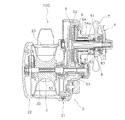
図1及び図2に示すように、両軸受リール100は、リール本体2、スプール3、ハンドル4、回転伝達機構5、及びドラグ機構6を備えている。
As shown in FIGS. 1 and 2, the dual-bearing
図2に示すように、リール本体2は、第1リール本体部21と第2リール本体部22とを有している。第1リール本体部21と第2リール本体部22とは、回転軸方向に互いに間隔をあけて配置されている。詳細には、第1リール本体部21はスプール3の第1端部側に配置され、第2リール本体部22はスプール3の第2端部側に配置される。第1リール本体部21と第2リール本体部22とは、互いに連結部23を介して連結されている。
As shown in FIG. 2, the
スプール3は、第1リール本体部21と第2リール本体部22との間に配置されている。スプール3の外周面には、釣糸が巻き付けられる。スプール3は、スプール軸30に固定され、スプール軸30と一体的に回転する。なお、スプール軸30は、第1リール本体部21と第2リール本体部22との間を延びている。スプール軸30は、軸受部材などを介して、第1及び第2リール本体部21,22に回転可能に支持されている。
The spool 3 is disposed between the
ハンドル4は、第1リール本体部21に回転可能に装着されている。詳細には、ハンドル4は、第1リール本体部21から突出した駆動軸51の第3回り止め部51c(図3参照)に取り付けられている。ハンドル4の回転は、回転伝達機構5を介してスプール3に伝達される。
The
回転伝達機構5は、ハンドル4の回転をスプール3に伝達する機構である。回転伝達機構5は、第1リール本体部21の内部空間内に配置されている。詳細には、回転伝達機構5は、駆動軸51、駆動ギア52、及びピニオンギア53を有する。
The rotation transmission mechanism 5 is a mechanism for transmitting the rotation of the
駆動軸51は、ハンドル4と連結されており、ハンドル4と一体的に回転する。なお、駆動軸51は、ワンウェイクラッチ54によって、釣糸繰り出し方向への回転が禁止される。図3に示すように、駆動軸51は、第1〜第3回り止め部51a〜51cを有している。各回り止め部51a〜51cは、互いに平行に延びる一対の平坦面によって構成されている。
The
図2に示すように、駆動ギア52は、駆動軸51に装着され、駆動軸51と一体的に回転する。ピニオンギア53は、駆動ギア52にかみ合う。なお、ピニオンギア53は筒状である。ピニオンギア53は、クラッチ機構55を介してスプール軸30と連結されている。クラッチ機構55がオン状態のとき、ピニオンギア53とスプール軸30は一体的に回転し、クラッチ機構55がオフ状態のときはピニオンギア53とスプール軸30とは相対回転可能となる。例えば、クラッチ機構55は、スプール軸30を径方向に貫通する係合ピンと、ピニオンギア53に形成された係合凹部とによって構成される。ピニオンギア53が軸方向に移動することによって、クラッチ機構55のオン状態とオフ状態とを切り替える。
As shown in FIG. 2, the
ドラグ機構6は、スプール3の釣糸繰り出し方向の回転を制動する機構である。図3に示すように、ドラグ機構6は、複数のドラグワッシャ61〜64、及び複数のライニング材65〜67を有している。ドラグワッシャ61〜64と、ライニング材65〜67とは、交互に配置されている。すなわち、各ドラグワッシャ61〜64の間にライニング材65〜67が配置されている。
The
各ドラグワッシャ61〜64は、駆動軸51の周囲に設けられている。駆動ギア52に向かって、第1ドラグワッシャ61、第2ドラグワッシャ62、第3ドラグワッシャ63、第4ドラグワッシャ64の順で配置されている。第1及び第3ドラグワッシャ61,63は、駆動軸51に係合し、駆動軸51と一体的に回転する。第2及び第4ドラグワッシャ62,64は、駆動ギア52に係合し、駆動ギア52と一体的に回転する。
The
各ドラグワッシャ61〜64、及び各ライニング材65〜67は、軸方向に移動可能である。押圧機構8によってドラグ機構6は駆動ギア52に向かって押圧されている。この押圧力によって、各ドラグワッシャ61〜64がライニング材65〜67を介して互いに摩擦係合している。この結果、駆動軸51からのトルクがドラグ機構6を介して駆動ギア52に伝達される。
Each
第1ドラグワッシャ61(本発明のワッシャの一例)は、駆動軸51(本発明の回転軸の一例)と係合して、駆動軸51と一体的に回転する。詳細には、第1ドラグワッシャ61は、駆動軸51の第1回り止め部51aと係合することによって、駆動軸51と一体的に回転する。また、第1ドラグワッシャ61は、駆動ギア52に対して相対回転する。
The first drag washer 61 (an example of the washer of the present invention) engages with the drive shaft 51 (an example of the rotary shaft of the present invention) and rotates integrally with the
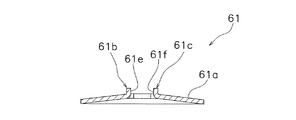
図4から図6に示すように、第1ドラグワッシャ61は、ワッシャ本体61aと、第1切り起こし部61b、第2切り起こし部61cとを有している。ワッシャ本体61aは、円板形状であって、中央部に貫通孔61dを有している。貫通孔61dを画定する内壁面は、第1平坦面61e及び第2平坦面61fを有している。貫通孔61dは、平面視において、非円形状である。具体的には、貫通孔61dは、略十字形状である。また、ワッシャ本体61aは、円錐台形状である。
As shown in FIGS. 4 to 6, the
第1及び第2切り起こし部61b、61cは、ワッシャ本体61aの内縁部の一部を切り起こして形成されている。第1及び第2切り起こし部61b、61cは、貫通孔61dが開口する方向(図5の上下方向)に延びている。すなわち、第1及び第2切り起こし部61b、61cは、ワッシャ本体61aから実質的に垂直に延びている。第1及び第2切り起こし部61b、61cは、互いに同じ方向に延びている。この第1切り起こし部61bは、第1平坦面61eを有している。また、第2切り起こし部61cは、第2平坦面61fを有している。
The first and second cut and raised
第1切り起こし部61bと、第2切り起こし部61cとは、対向するように配置されている。詳細には、第1切り起こし部61bの第1平坦面61eと、第2切り起こし部61cの第2平坦面61fとが、互いに向き合うように構成されている。詳細には、第1平坦面61eと第2平坦面61fとは、互いに平行に延びている。この第1平坦面61e及び第2平坦面61fが、駆動軸51の第1回り止め部51aと係合する。第1平坦面61e及び第2平坦面61fの高さhは、ワッシャ本体61aの厚さよりも大きい。なお、第1平坦面61e及び第2平坦面61fの高さhとは、貫通孔61dが開口する方向の寸法を意味し、具体的には、図7に示すように、ワッシャ本体61aの底面からの高さhを意味する。このように構成することによって、第1ドラグワッシャ61と第1回り止め部51aとが接触する面積を大きくすることができる。
The first cut and raised
また、第1ドラグワッシャ61は、ワンウェイクラッチ54の内輪54aと一体回転する。具体的には、図4に示すように、第1ドラグワッシャ61の貫通孔61dは、一対の係合凹部61gを有している、一対の係合凹部61gは、互いに向き合うように配置されている。この各係合凹部61gに、ワンウェイクラッチ54の内輪54aの係合凸部54bが係合する。この結果、第1ドラグワッシャ61は、ワンウェイクラッチ54の内輪54aと一体回転する。
The
図3に示すように、第3ドラグワッシャ63は、駆動軸51と係合して、駆動軸51と一体的に回転する。詳細には、第3ドラグワッシャ63は、駆動軸51の第2回り止め部51bと係合して、駆動軸51と一体的に回転する。また、第3ドラグワッシャ63は、駆動ギア52に対して相対回転する。
As shown in FIG. 3, the
第2及び第4ドラグワッシャ62、64は、駆動ギア52と一体的に回転する。また、第2及び第4ドラグワッシャ62,64は、駆動軸51に対して相対回転する。詳細には、第2ドラグワッシャ62は、一対の係合凸部62aを外周縁部に有している。各係合凸部62aは、駆動ギア52の係合凹部52aと係合する。これにより、第2ドラグワッシャ62は、駆動ギア52と一体的に回転する。第4ドラグワッシャ64は、一対の係合凸部64aを外周縁部に有している。第4ドラグワッシャ64の各係合凸部64aも、駆動ギア52の係合凹部52aと係合する。これにより、第4ドラグワッシャ64は、駆動ギア52と一体的に回転する。
The second and
スタードラグ7は、ドラグ機構6のドラグ力を調節するためのものである。図2に示すように、スタードラグ7は、押圧機構8を介して、ドラグ機構6のドラグ力を調節する。なお、押圧機構8は、具体的には、ワンウェイクラッチ54の内輪54a、軸受部材81、皿バネ82、及びコイルスプリング83などを有している。スタードラグ7は、駆動軸51の雄ネジ部51dと螺合している。スタードラグ7を回転させると、スタードラグ7は、軸方向において移動する。このスタードラグ7の移動によって、ドラグ機構6に対する押圧機構8の押圧力が変化し、この結果、ドラグ機構6のドラグ力が調節される。
The star drag 7 is for adjusting the drag force of the
上記実施形態に係る第1ドラグワッシャ61によれば、第1切り起こし部61bが駆動軸51と当接する。このため、貫通孔61dの内壁面が駆動軸51と当接する場合に比べて、駆動軸51と接触する面積を増やすことができる。この結果、第1ドラグワッシャ61を薄くした場合であって、変形することなく駆動軸51からのトルクを十分に受けることができる。
According to the
[変形例]
以上、本発明の実施形態について説明したが、本発明はこれらに限定されるものではなく、本発明の趣旨を逸脱しない限りにおいて種々の変更が可能である。
[Modification]
As mentioned above, although embodiment of this invention was described, this invention is not limited to these, A various change is possible unless it deviates from the meaning of this invention.
変形例1
上記実施形態では、第1ドラグワッシャ61に、本発明を適用したが、第3ドラグワッシャ63に本発明を適用することができる。すなわち、第3ドラグワッシャ63のワッシャ本体の内縁部を切り起こして、少なくとも1つの切り起こし部を形成してもよい。
Modification 1
Although the present invention is applied to the
変形例2
上記実施形態では、両軸受リール100の第1ドラグワッシャ61に本発明を適用したが、スピニングリールのドラグワッシャに本発明を適用することもできる。
Although the present invention is applied to the
61 第1ドラグワッシャ
61a ワッシャ本体
61b 第1切り起こし部
61c 第2切り起こし部
61d 貫通孔
61e 第1平坦面
61f 第2平坦面
61
Claims (6)
第1平坦面を有する内壁面によって画定される貫通孔を中央部に有するワッシャ本体と、
前記第1平坦面を有する第1切り起こし部と、
を備える、ドラグワッシャ。
A drag washer for use in a drag mechanism of a fishing reel mounted so as to rotate integrally with a rotating shaft, abutting on the lining material on one side and engaging the inner ring of the one-way clutch on the other side ,
A washer body having at its center a through hole defined by an inner wall surface having a first flat surface;
A first cut-and-raised portion having the first flat surface;
Equipped with a drag washer.
請求項1に記載のドラグワッシャ。
The first cut-and-raised portion extends in a direction in which the through hole opens.
The drag washer according to claim 1.
前記内壁面は、第2平坦面を有し、
前記第2切り起こし部は、前記第2平坦面を有する、
請求項1又は2に記載のドラグワッシャ。
It is further equipped with a second raising part,
The inner wall surface has a second flat surface,
The second cut and raised portion has the second flat surface,
A drag washer according to claim 1 or 2.
請求項3に記載のドラグワッシャ。
The second cut and raised portion extends in the same direction as the first cut and raised portion.
A drag washer according to claim 3.
請求項3又は4に記載のドラグワッシャ。
The second flat surface extends parallel to the first flat surface,
The drag washer according to claim 3 or 4.
請求項1から5のいずれかに記載のドラグワッシャ。 The washer body is frusto-conical in shape,
The drag washer according to any one of claims 1 to 5.
Priority Applications (5)
| Application Number | Priority Date | Filing Date | Title |
|---|---|---|---|
| JP2015079950A JP6542567B2 (en) | 2015-04-09 | 2015-04-09 | Fishing reel washer |
| US15/057,564 US10045519B2 (en) | 2015-04-09 | 2016-03-01 | Washer for fishing reel |
| TW105107198A TWI667957B (en) | 2015-04-09 | 2016-03-09 | Drag washer for fishing reel |
| KR1020160036820A KR102573716B1 (en) | 2015-04-09 | 2016-03-28 | Washer for fishing reel |
| CN201610202576.5A CN106050885B (en) | 2015-04-09 | 2016-04-01 | Washer of fishing reel |
Applications Claiming Priority (1)
| Application Number | Priority Date | Filing Date | Title |
|---|---|---|---|
| JP2015079950A JP6542567B2 (en) | 2015-04-09 | 2015-04-09 | Fishing reel washer |
Publications (3)
| Publication Number | Publication Date |
|---|---|
| JP2016198032A JP2016198032A (en) | 2016-12-01 |
| JP2016198032A5 JP2016198032A5 (en) | 2018-04-26 |
| JP6542567B2 true JP6542567B2 (en) | 2019-07-10 |
Family
ID=57111175
Family Applications (1)
| Application Number | Title | Priority Date | Filing Date |
|---|---|---|---|
| JP2015079950A Active JP6542567B2 (en) | 2015-04-09 | 2015-04-09 | Fishing reel washer |
Country Status (5)
| Country | Link |
|---|---|
| US (1) | US10045519B2 (en) |
| JP (1) | JP6542567B2 (en) |
| KR (1) | KR102573716B1 (en) |
| CN (1) | CN106050885B (en) |
| TW (1) | TWI667957B (en) |
Families Citing this family (2)
| Publication number | Priority date | Publication date | Assignee | Title |
|---|---|---|---|---|
| US11278015B2 (en) | 2020-01-22 | 2022-03-22 | DQC International Corp. | Fishing reel drag system |
| JP2022174810A (en) * | 2021-05-12 | 2022-11-25 | 株式会社シマノ | Double bearing reel |
Family Cites Families (32)
| Publication number | Priority date | Publication date | Assignee | Title |
|---|---|---|---|---|
| US2071474A (en) * | 1935-02-04 | 1937-02-23 | Bronson Reel Company | Fishing reel |
| US3892031A (en) * | 1972-04-05 | 1975-07-01 | Southco | Method of capturing screw fastener |
| JPS56101214U (en) * | 1979-07-02 | 1981-08-08 | ||
| US4402469A (en) * | 1981-07-31 | 1983-09-06 | Brunswick Corporation | Self-aligning drag drive for fishing reels |
| JPS5982032A (en) * | 1982-11-02 | 1984-05-11 | 大丸興業株式会社 | Drag mechanism of fishing reel |
| JPH0569411U (en) * | 1992-02-27 | 1993-09-21 | 株式会社三ツ葉電機製作所 | Lock nut lock washer |
| JP3672330B2 (en) * | 1993-04-05 | 2005-07-20 | トヨタ自動車株式会社 | Damping structure |
| JP3005412B2 (en) | 1994-01-21 | 2000-01-31 | 三洋電機株式会社 | Facsimile machine |
| JP3005412U (en) * | 1994-06-20 | 1994-12-20 | ダイワ精工株式会社 | Fishing reel |
| US5915902A (en) * | 1997-09-19 | 1999-06-29 | Illinois Tool Works Inc. | Undeformed lock nut with slot |
| JP2002238421A (en) * | 2001-02-16 | 2002-08-27 | Daiwa Seiko Inc | Lining material for fishing reel and method for producing the same |
| JP2003023934A (en) | 2001-07-19 | 2003-01-28 | Daiwa Seiko Inc | Double bearing reel for fishing |
| US6669419B1 (en) * | 2002-01-25 | 2003-12-30 | Radio Systems Corporation | Probe locking washer |
| KR100466532B1 (en) * | 2003-01-16 | 2005-01-15 | 주식회사 바낙스 | fly reel |
| US7326017B2 (en) * | 2004-03-17 | 2008-02-05 | Metallwarenfabrik Hermann Winker Gmbh & Co.Kg | Fastening element, washer and fastening means therefrom |
| US8092129B2 (en) * | 2006-04-21 | 2012-01-10 | Hubbell Incorporated | Bonding washer |
| US8534583B2 (en) * | 2006-08-04 | 2013-09-17 | Accurate Fishing Products | Drag mechanism for a fishing reel |
| US7654483B1 (en) * | 2007-04-12 | 2010-02-02 | Penn Fishing Tackle Manufacturing Co. | Disengagable adjustable drag system for a fishing reel |
| US7552886B2 (en) * | 2007-07-10 | 2009-06-30 | W.C. Bradley/Zebco Holdings, Inc. | Double drag, pre-set adjust and unitary end assembly for trolling reel |
| ES2293860B1 (en) * | 2007-10-01 | 2009-02-01 | Hierros Y Aplanaciones, S.A. (Hiasa) | DIRECT FUSE ANCHOR SYSTEM FOR SUPPORT POST OF A SAFETY OR PRETIL BARRIER ON A RIGID GROUND. |
| JP4717055B2 (en) * | 2007-12-18 | 2011-07-06 | 神鋼ボルト株式会社 | Washer |
| JP5198083B2 (en) * | 2008-02-05 | 2013-05-15 | ミネベアモータ株式会社 | Brushless motor |
| JP4903181B2 (en) * | 2008-06-20 | 2012-03-28 | グローブライド株式会社 | Fishing reel |
| JP5292152B2 (en) * | 2009-03-26 | 2013-09-18 | 株式会社シマノ | Fishing reel handle arm mounting structure |
| TWM391262U (en) * | 2010-05-24 | 2010-10-21 | Hon Hai Prec Ind Co Ltd | Hinge and interference member of the same |
| JP5507374B2 (en) * | 2010-07-26 | 2014-05-28 | 株式会社シマノ | Drag bearing device for dual-bearing reel |
| JP5536594B2 (en) * | 2010-09-02 | 2014-07-02 | 株式会社シマノ | Double bearing reel |
| US20120206852A1 (en) * | 2011-02-10 | 2012-08-16 | Honda Motor Co., Ltd. | Notched washer to improve surface area for grounding of conductive plastics |
| US9133869B2 (en) * | 2011-08-01 | 2015-09-15 | Elringklinger Ag | Shielding device with a shielding element and at least one temperature and oscillation-decoupled fastening device |
| KR101380666B1 (en) * | 2012-02-22 | 2014-04-04 | 주식회사 도요엔지니어링 | Fishing reel equipped with fine tuning means for drag power |
| US9689411B2 (en) * | 2012-07-05 | 2017-06-27 | Ironridge, Inc. | Assembly for clamping and grounding objects |
| US8888431B2 (en) * | 2013-03-15 | 2014-11-18 | Hubbell Incorporated | Adjustable bonding washer |
-
2015
- 2015-04-09 JP JP2015079950A patent/JP6542567B2/en active Active
-
2016
- 2016-03-01 US US15/057,564 patent/US10045519B2/en active Active
- 2016-03-09 TW TW105107198A patent/TWI667957B/en active
- 2016-03-28 KR KR1020160036820A patent/KR102573716B1/en active IP Right Grant
- 2016-04-01 CN CN201610202576.5A patent/CN106050885B/en active Active
Also Published As
| Publication number | Publication date |
|---|---|
| US10045519B2 (en) | 2018-08-14 |
| KR102573716B1 (en) | 2023-09-04 |
| CN106050885B (en) | 2021-12-17 |
| CN106050885A (en) | 2016-10-26 |
| TWI667957B (en) | 2019-08-11 |
| JP2016198032A (en) | 2016-12-01 |
| TW201700009A (en) | 2017-01-01 |
| US20160295845A1 (en) | 2016-10-13 |
| KR20160121403A (en) | 2016-10-19 |
Similar Documents
| Publication | Publication Date | Title |
|---|---|---|
| US10514080B2 (en) | Torsional vibration reducing device | |
| JP6560903B2 (en) | Double bearing reel | |
| EP2245926B1 (en) | Spool for dual-bearing reel | |
| KR102442021B1 (en) | Dual bearing reel | |
| JP6649801B2 (en) | Double bearing reel | |
| TWI377909B (en) | Dual bearing reel | |
| JP6542567B2 (en) | Fishing reel washer | |
| US9545088B2 (en) | Fishing reel | |
| KR102491582B1 (en) | Dual-bearing reel | |
| KR102562262B1 (en) | Dual-bearing reel | |
| JP5204631B2 (en) | Fishing reel | |
| JP2016198032A5 (en) | ||
| US10883553B2 (en) | One-way clutch | |
| JP6965124B2 (en) | Double bearing reel | |
| JP6971612B2 (en) | Double bearing reel | |
| KR102505157B1 (en) | Dual-bearing reel | |
| JP2013226055A (en) | Reel body of dual-bearing reel and dual-bearing reel | |
| JP2010148459A (en) | Spinning reel | |
| US11997996B2 (en) | Spool braking device for dual bearing reel | |
| JP7345348B2 (en) | double bearing reel | |
| JP2008051167A (en) | Torque limiter | |
| JP6987612B2 (en) | Roller clutch for fishing reel | |
| EP1977132B1 (en) | Support piece for braking element |
Legal Events
| Date | Code | Title | Description |
|---|---|---|---|
| A521 | Request for written amendment filed |
Free format text: JAPANESE INTERMEDIATE CODE: A523 Effective date: 20180316 |
|
| A621 | Written request for application examination |
Free format text: JAPANESE INTERMEDIATE CODE: A621 Effective date: 20180316 |
|
| A977 | Report on retrieval |
Free format text: JAPANESE INTERMEDIATE CODE: A971007 Effective date: 20181226 |
|
| A131 | Notification of reasons for refusal |
Free format text: JAPANESE INTERMEDIATE CODE: A131 Effective date: 20190129 |
|
| A521 | Request for written amendment filed |
Free format text: JAPANESE INTERMEDIATE CODE: A523 Effective date: 20190219 |
|
| TRDD | Decision of grant or rejection written | ||
| A01 | Written decision to grant a patent or to grant a registration (utility model) |
Free format text: JAPANESE INTERMEDIATE CODE: A01 Effective date: 20190604 |
|
| A61 | First payment of annual fees (during grant procedure) |
Free format text: JAPANESE INTERMEDIATE CODE: A61 Effective date: 20190613 |
|
| R150 | Certificate of patent or registration of utility model |
Ref document number: 6542567 Country of ref document: JP Free format text: JAPANESE INTERMEDIATE CODE: R150 |
|
| R250 | Receipt of annual fees |
Free format text: JAPANESE INTERMEDIATE CODE: R250 |
|
| S111 | Request for change of ownership or part of ownership |
Free format text: JAPANESE INTERMEDIATE CODE: R313113 |
|
| R350 | Written notification of registration of transfer |
Free format text: JAPANESE INTERMEDIATE CODE: R350 |
|
| R250 | Receipt of annual fees |
Free format text: JAPANESE INTERMEDIATE CODE: R250 |
|
| R250 | Receipt of annual fees |
Free format text: JAPANESE INTERMEDIATE CODE: R250 |