EP2783166B1 - Dispositif pour ajuster un débit d'air s'écoulant dans un conduit aéraulique - Google Patents
Dispositif pour ajuster un débit d'air s'écoulant dans un conduit aéraulique Download PDFInfo
- Publication number
- EP2783166B1 EP2783166B1 EP12795545.8A EP12795545A EP2783166B1 EP 2783166 B1 EP2783166 B1 EP 2783166B1 EP 12795545 A EP12795545 A EP 12795545A EP 2783166 B1 EP2783166 B1 EP 2783166B1
- Authority
- EP
- European Patent Office
- Prior art keywords
- ring
- drive means
- flap
- male
- axis
- Prior art date
- Legal status (The legal status is an assumption and is not a legal conclusion. Google has not performed a legal analysis and makes no representation as to the accuracy of the status listed.)
- Active
Links
Images


Classifications
-
- F—MECHANICAL ENGINEERING; LIGHTING; HEATING; WEAPONS; BLASTING
- F15—FLUID-PRESSURE ACTUATORS; HYDRAULICS OR PNEUMATICS IN GENERAL
- F15D—FLUID DYNAMICS, i.e. METHODS OR MEANS FOR INFLUENCING THE FLOW OF GASES OR LIQUIDS
- F15D1/00—Influencing flow of fluids
- F15D1/02—Influencing flow of fluids in pipes or conduits
- F15D1/025—Influencing flow of fluids in pipes or conduits by means of orifice or throttle elements
-
- F—MECHANICAL ENGINEERING; LIGHTING; HEATING; WEAPONS; BLASTING
- F24—HEATING; RANGES; VENTILATING
- F24F—AIR-CONDITIONING; AIR-HUMIDIFICATION; VENTILATION; USE OF AIR CURRENTS FOR SCREENING
- F24F13/00—Details common to, or for air-conditioning, air-humidification, ventilation or use of air currents for screening
- F24F13/08—Air-flow control members, e.g. louvres, grilles, flaps or guide plates
- F24F13/10—Air-flow control members, e.g. louvres, grilles, flaps or guide plates movable, e.g. dampers
- F24F13/14—Air-flow control members, e.g. louvres, grilles, flaps or guide plates movable, e.g. dampers built up of tilting members, e.g. louvre
-
- G—PHYSICS
- G05—CONTROLLING; REGULATING
- G05D—SYSTEMS FOR CONTROLLING OR REGULATING NON-ELECTRIC VARIABLES
- G05D7/00—Control of flow
- G05D7/03—Control of flow with auxiliary non-electric power
-
- F—MECHANICAL ENGINEERING; LIGHTING; HEATING; WEAPONS; BLASTING
- F24—HEATING; RANGES; VENTILATING
- F24F—AIR-CONDITIONING; AIR-HUMIDIFICATION; VENTILATION; USE OF AIR CURRENTS FOR SCREENING
- F24F13/00—Details common to, or for air-conditioning, air-humidification, ventilation or use of air currents for screening
- F24F13/08—Air-flow control members, e.g. louvres, grilles, flaps or guide plates
- F24F13/10—Air-flow control members, e.g. louvres, grilles, flaps or guide plates movable, e.g. dampers
- F24F13/14—Air-flow control members, e.g. louvres, grilles, flaps or guide plates movable, e.g. dampers built up of tilting members, e.g. louvre
- F24F13/1426—Air-flow control members, e.g. louvres, grilles, flaps or guide plates movable, e.g. dampers built up of tilting members, e.g. louvre characterised by actuating means
- F24F2013/1473—Air-flow control members, e.g. louvres, grilles, flaps or guide plates movable, e.g. dampers built up of tilting members, e.g. louvre characterised by actuating means with cams or levers
Definitions
- the present invention relates to a device for adjusting a flow of air flowing in a ventilation duct.
- This device finds particular application for the equipment of a mechanical ventilation system (VMC) or air conditioning of a room.
- VMC mechanical ventilation system
- FIG. figure 1 A device 1 for adjusting a flow rate of air flowing in a ventilation duct, known from the state of the art, is represented in FIG. figure 1 .
- This device 1 comprises a tubular body 2 designed to be engaged entirely within the air duct.
- the device 1 comprises a seal 4 mounted on the body 2 to seal between the body 2 and the air duct.
- the device 1 comprises flaps 6 provided to occupy a plurality of positions within the body 2 corresponding to a plurality of air passage sections.
- the body 2 comprises grooves 8 and the flaps 6 comprise ribs of complementary shapes arranged to slide in said grooves 8.
- the device 1 finally comprises a flexible chamber 10 adapted to inflate or deflate according to the pressure difference between upstream and downstream end portions of the body 2.
- the invention aims to remedy this drawback.
- each flap is provided with the male drive means, and the ring is provided with the female drive means.
- axis transverse to the axis of the body an axis belonging to a plane transverse to the axis of the body.
- the installer When an installer wishes to preset or adjust the air flow flowing in an air duct equipped with the device according to the invention, the installer simply drives the ring in rotation relative to the body.
- the male and female drive means cooperate and move each flap inside the body so as to reduce or increase the air passage section.
- each flap extends at an upstream end portion of the body, in the air flow direction, and the male and female drive means are arranged at the a downstream end portion.
- the male drive means comprises a finger
- the female drive means comprises a tab extending in a plane transverse to the axis of the body and through which is formed a C-shaped light adapted to receive the finger .
- Such an arrangement makes it possible to convert the pivoting of the ring relative to the body about the axis of this body into a pivoting of the flap inside the body around its pivot axis.
- the light has two end portions shaped to receive and immobilize the finger.
- each flap is molded with the body, and each flap has a thinning material defining the pivot axis of the flap.
- each shutter and the body is carried out jointly by molding.
- the number of elements constituting the device is limited and the assembly method of the device is facilitated.
- the body is provided with a male detent member and the ring is provided with a female detent member, or vice versa, the male and female detent members being adapted to prohibit the axial translation of the detent. ring on the body, and allow the ring to pivot on the body.
- the ring has a fluted outer face.
- the ring has an outer diameter substantially equal to the outer diameter of the body, and preferably an inner diameter substantially equal to the inner diameter of the body.
- the device can then be engaged in its entirety inside an air duct whose inner diameter is substantially equal to the outer diameter of the body and the ring.
- the device comprises a flexible chamber arranged to inflate or deflate, as a function of the pressure difference between the upstream and downstream end portions of the body.
- Such a flexible chamber makes it possible to regulate the flow rate of air flowing in the air duct around a setpoint value, whatever the airflow disturbances to which the duct is subjected.
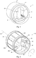
- the device 20 comprises a tubular body 22 extending along an axis 24.
- the body 22 is intended to be fluidly connected to said air duct.
- the body 22 is for example engaged in part or entirely in the air duct.
- the body 22 has an upstream end portion 22a and a downstream end portion 22b.
- the body 22 is provided with a male detent member 26 (shown in FIGS. figures 3 and 9 ) provided on the downstream end portion 22b.
- the male detent member 26 here takes the form of an annular projection.
- the shutters 28 are molded with the body 22 and have material thinning (shown in FIG. figure 9 ) defining the axes 30. These axes 30 extend at the upstream end portion 22a of the body 22 and are transverse to the axis 24.
- the flaps 28 are provided with fingers 32 forming male drive means.
- the fingers 32 are arranged at the level of the downstream end portion 22b.
- the device 20 comprises a ring 34 pivotally mounted on the downstream end portion 22b of the body 22 about the axis 24.
- the ring 34 has an outer diameter substantially equal to the outer diameter of the body 22 and an inner diameter substantially equal to the inner diameter of the body 22.
- the ring 34 has a fluted outer face
- the ring 34 is provided with tabs 36 in which are formed C-shaped openings 38 forming female drive means.
- the tabs 36 extend at the level of the downstream end portion 22a, in a plane transverse to the axis 24.
- the lights 38 are adapted to receive the fingers 32. More specifically, the lights 38 have a width slightly greater than the width of the fingers 32. Thus, the sliding of the fingers 32 in the slots 38, when the flaps 28 pivot about the pins 30 , is made possible.
- the lights 38 have two end portions 38a and 38b (shown in FIGS. Figures 4 to 6 ) shaped to accommodate and immobilize the fingers 32.
- the ring 34 is provided with a female detent 40 (shown in FIG. figure 9 ).
- the female latching member 40 here takes the form of an annular groove.
- the male and female ratching members 40 are designed to prevent the axial translation of the ring 34 on the body 22, and to allow the ring 34 to pivot on the body 22.
- the device 20 finally comprises a regulating member 42 adapted to regulate the flow of air flowing in the body 22 around a set value.
- the regulator 42 (shown in FIG. figure 11 ) comprises a flexible chamber 44 arranged to inflate, or to deflate, depending on the pressure difference between the upstream end portion 22a and the downstream portion 22b of the body 22.
- the flexible chamber 44 is mounted on a base 46.
- the regulating member 42 comprises a support 48 on which is fixed a reinforcement 50 engaged inside the flexible chamber 44.
- the regulator member 42 finally comprises a cover 52 having an opening 54 inside which the flexible chamber 44 is engaged.
- the cover 52 and the support 48 enclose the base 46.
- the cover 52, the support 48 and the base 46 are engaged in a housing 54 (shown in FIG. figure 10 ) formed inside the body 22, so that the flexible chamber 44 extends radially inside the body 22 between the flaps 28.
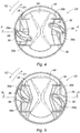
- the ring 34 is mounted on the body 22 (as shown in FIG. figure 4 ).
- the fingers 32 are received and immobilized by the end portions 38a of the slots 38.
- the flaps 28 are in the separated position.
- the fingers 32 are then released by the end portions 38a and slide inside the slots 38 until they are received and immobilized by the end portions 38b.
- the flaps 28 pivot about the axes 30 so as to successively occupy their intermediate position (represented in FIG. figure 5 ) then their close position (represented in figure 6 ).
- the installer When the installer wishes to increase the air passage section, and consequently the flow of air flowing in the air duct, it causes the ring 34 to rotate about the axis 24 in a direction opposite S2 in the sense S1.
- the fingers 32 are then released by the end portions 38b and slide inside the lumens 38 until they are received and immobilized by the end portions 38b.
- the flaps 28 pivot about the axes 30 so as to successively occupy their intermediate position (represented in FIG. figure 5 ) then their close position (represented in figure 6 ).
- the invention is not limited to the sole embodiment of the device described above by way of example, it encompasses all the variants.
- the ring may be provided with a male drive member and each flap may be provided with a female drive member.
- These male and female drive means are arranged such that in response to a pivoting of the ring on the body, the male drive means cooperates with the female drive means to change the position of each flap, and as a result the air passage section.
- the ring and the body have complementary indexing means adapted to receive and immobilize the ring in three predetermined positions relative to the body, corresponding to the spaced apart, intermediate and close positions of the flaps.
- the indexing means comprise a plurality of notches formed on an inner face of the ring. These notches are arranged to cooperate with at least one boss formed on the body.
Landscapes
- Engineering & Computer Science (AREA)
- Mechanical Engineering (AREA)
- General Engineering & Computer Science (AREA)
- Physics & Mathematics (AREA)
- Chemical & Material Sciences (AREA)
- Combustion & Propulsion (AREA)
- Power Engineering (AREA)
- General Physics & Mathematics (AREA)
- Automation & Control Theory (AREA)
- Fluid Mechanics (AREA)
- Air-Flow Control Members (AREA)
Priority Applications (1)
| Application Number | Priority Date | Filing Date | Title |
|---|---|---|---|
| PL12795545T PL2783166T3 (pl) | 2011-11-23 | 2012-11-14 | Urządzenie do dostosowywania natężenia przepływu powietrza płynącego w kanale wentylacyjnym |
Applications Claiming Priority (2)
| Application Number | Priority Date | Filing Date | Title |
|---|---|---|---|
| FR1160687A FR2982934B1 (fr) | 2011-11-23 | 2011-11-23 | Dispositif pour ajuster un debit d'air s'ecoulant dans un conduit aeraulique |
| PCT/FR2012/052625 WO2013076404A1 (fr) | 2011-11-23 | 2012-11-14 | Dispositif pour ajuster un débit d'air s'écoulant dans un conduit aéraulique |
Publications (2)
| Publication Number | Publication Date |
|---|---|
| EP2783166A1 EP2783166A1 (fr) | 2014-10-01 |
| EP2783166B1 true EP2783166B1 (fr) | 2018-04-25 |
Family
ID=47291139
Family Applications (1)
| Application Number | Title | Priority Date | Filing Date |
|---|---|---|---|
| EP12795545.8A Active EP2783166B1 (fr) | 2011-11-23 | 2012-11-14 | Dispositif pour ajuster un débit d'air s'écoulant dans un conduit aéraulique |
Country Status (11)
| Country | Link |
|---|---|
| US (1) | US9631649B2 (pl) |
| EP (1) | EP2783166B1 (pl) |
| CN (1) | CN103988028B (pl) |
| AU (1) | AU2012342295B2 (pl) |
| CA (1) | CA2851582C (pl) |
| DK (1) | DK2783166T3 (pl) |
| ES (1) | ES2678206T3 (pl) |
| FR (1) | FR2982934B1 (pl) |
| PL (1) | PL2783166T3 (pl) |
| RU (1) | RU2597538C2 (pl) |
| WO (1) | WO2013076404A1 (pl) |
Cited By (1)
| Publication number | Priority date | Publication date | Assignee | Title |
|---|---|---|---|---|
| WO2022101056A1 (de) | 2020-11-13 | 2022-05-19 | Viessmann Climate Solutions Se | Einrichtung zum einstellen eines luftvolumenstroms |
Families Citing this family (1)
| Publication number | Priority date | Publication date | Assignee | Title |
|---|---|---|---|---|
| CN113062767B (zh) * | 2021-04-12 | 2021-11-19 | 徐州中国矿大岩土工程新技术发展有限公司 | 一种自加压的水泥浆液泵送管系统 |
Family Cites Families (21)
| Publication number | Priority date | Publication date | Assignee | Title |
|---|---|---|---|---|
| US2895610A (en) * | 1956-06-04 | 1959-07-21 | Post Office | Segregating apparatus |
| US2934892A (en) * | 1957-01-31 | 1960-05-03 | Westinghouse Electric Corp | Variable area propulsion nozzle |
| DE1214548B (de) * | 1963-06-01 | 1966-04-14 | Fichtel & Sachs Ag | Vorrichtung zur Verringerung der Betaetigungskraefte von Kupplungen, insbesondere Kraftfahrzeugkupplungen |
| DE1604121A1 (de) * | 1965-07-08 | 1970-09-10 | Aaberg C | Anlage zur Bewerkstelligung von Lufterneuerung in Raeumen,insbesondere Staellen |
| BE794240A (fr) * | 1972-01-21 | 1973-05-16 | Trox Gmbh Geb | Dispositif pour le reglage de fluides en ecoulement, en particulier d'air dans des installations d'aeration ou de climatisation |
| US3997132A (en) * | 1974-12-11 | 1976-12-14 | The Garrett Corporation | Method and apparatus for controlling tip vortices |
| US4018159A (en) * | 1975-09-04 | 1977-04-19 | General Motors Corporation | Air flow guide mechanism |
| US4094492A (en) * | 1977-01-18 | 1978-06-13 | The United States Of America As Represented By The United States Department Of Energy | Variable orifice using an iris shutter |
| SU659844A1 (ru) * | 1977-08-17 | 1979-04-30 | А. И. Лисицын и В. А. Мангасар н | Вентил ционный клапан |
| FR2466715B1 (fr) * | 1979-10-05 | 1986-08-14 | Serva Soc | Stabilisateur de debit pour conduit de ventilation |
| JPS6115443U (ja) * | 1984-06-30 | 1986-01-29 | 東プレ株式会社 | 空気調和用定風量装置 |
| FR2595453B1 (fr) * | 1986-03-05 | 1988-05-13 | Aldes Atel Lyonnais Emboutissa | Bouche de ventilation a debit variable |
| SU1809657A1 (ru) * | 1988-04-11 | 1997-01-10 | В.П. Лапшин | Воздушный клапан |
| CN1090739C (zh) * | 1997-09-25 | 2002-09-11 | 煜丰企业有限公司 | 可依空调能量大小调节出风口截面积的控制装置 |
| US6231438B1 (en) * | 2000-04-21 | 2001-05-15 | Gebruder Trox Gmbh | Manually adjustable underfloor airflow damper assembly |
| GB2425971B (en) * | 2005-05-11 | 2010-06-30 | Gaim Ltd | A Flow Distributor |
| CN2861848Y (zh) * | 2005-12-13 | 2007-01-24 | 妥思空调设备(苏州)有限公司 | 风量调节器 |
| DE102008005699B4 (de) * | 2008-01-23 | 2019-05-16 | Emz-Hanauer Gmbh & Co. Kgaa | Luftklappenvorrichtung für ein Kühl- oder/und Gefriergerät für Küchenausstattung |
| KR101150658B1 (ko) * | 2008-08-29 | 2012-05-29 | 이근상 | 조리개식 가변밸브 |
| US8220496B2 (en) * | 2009-06-04 | 2012-07-17 | National Oilwell Varco, L.P. | Apparatus for reducing turbulence in a fluid stream |
| JP6094366B2 (ja) * | 2013-02-21 | 2017-03-15 | 豊田合成株式会社 | ダンパ開閉装置 |
-
2011
- 2011-11-23 FR FR1160687A patent/FR2982934B1/fr not_active Expired - Fee Related
-
2012
- 2012-11-14 CA CA2851582A patent/CA2851582C/fr active Active
- 2012-11-14 AU AU2012342295A patent/AU2012342295B2/en not_active Ceased
- 2012-11-14 PL PL12795545T patent/PL2783166T3/pl unknown
- 2012-11-14 DK DK12795545.8T patent/DK2783166T3/en active
- 2012-11-14 EP EP12795545.8A patent/EP2783166B1/fr active Active
- 2012-11-14 WO PCT/FR2012/052625 patent/WO2013076404A1/fr not_active Ceased
- 2012-11-14 RU RU2014119834/12A patent/RU2597538C2/ru active
- 2012-11-14 CN CN201280057362.3A patent/CN103988028B/zh active Active
- 2012-11-14 ES ES12795545.8T patent/ES2678206T3/es active Active
- 2012-11-14 US US14/359,800 patent/US9631649B2/en active Active
Non-Patent Citations (1)
| Title |
|---|
| None * |
Cited By (2)
| Publication number | Priority date | Publication date | Assignee | Title |
|---|---|---|---|---|
| WO2022101056A1 (de) | 2020-11-13 | 2022-05-19 | Viessmann Climate Solutions Se | Einrichtung zum einstellen eines luftvolumenstroms |
| EP4001793A1 (de) | 2020-11-13 | 2022-05-25 | Viessmann Climate Solutions SE | Einrichtung zum einstellen eines luftvolumenstroms |
Also Published As
| Publication number | Publication date |
|---|---|
| CA2851582A1 (fr) | 2013-05-30 |
| FR2982934A1 (fr) | 2013-05-24 |
| US20140305528A1 (en) | 2014-10-16 |
| RU2597538C2 (ru) | 2016-09-10 |
| FR2982934B1 (fr) | 2013-11-29 |
| RU2014119834A (ru) | 2015-12-27 |
| WO2013076404A1 (fr) | 2013-05-30 |
| PL2783166T3 (pl) | 2018-10-31 |
| CA2851582C (fr) | 2019-08-27 |
| US9631649B2 (en) | 2017-04-25 |
| ES2678206T3 (es) | 2018-08-09 |
| AU2012342295B2 (en) | 2017-07-13 |
| EP2783166A1 (fr) | 2014-10-01 |
| AU2012342295A1 (en) | 2014-05-15 |
| DK2783166T3 (en) | 2018-08-06 |
| CN103988028B (zh) | 2017-03-08 |
| CN103988028A (zh) | 2014-08-13 |
Similar Documents
| Publication | Publication Date | Title |
|---|---|---|
| FR2606845A1 (fr) | Palier a fluide | |
| EP2783166B1 (fr) | Dispositif pour ajuster un débit d'air s'écoulant dans un conduit aéraulique | |
| EP1048997A1 (fr) | Cartouche de robinet mitigeur à limitation de température | |
| WO2020109685A1 (fr) | Aerateur mince a effet coanda pour vehicule automobile | |
| EP2452130B1 (fr) | Conduit de section générale circulaire, équipé d'un dispositif de régulation du débit d'air | |
| EP3599403B1 (fr) | Dispositif de réglage réglable depuis une première extrémité et une seconde extrémité du dispositif de réglage | |
| EP0087989B1 (fr) | Stabilisateur de débit pour conduit de ventilation | |
| FR2792256A1 (fr) | Aerateur, notamment pour habitacle de vehicule automobile | |
| EP3077291B1 (fr) | Suspension réglable d'un moteur pour le positionner par rapport à son support | |
| EP0634613A1 (fr) | Régulateur automatique de débit pour installations de ventilation et de conditionnement d'air | |
| EP2018502B1 (fr) | Bouche de ventilation auto-réglable à débits multiples | |
| CA3098947C (en) | Valve housing assembly | |
| EP3442817A1 (fr) | Dispositif de diffusion d'air a fuites reduites en configuration de fermeture | |
| EP1926191A1 (fr) | Boîtier d'appareillage électrique, à face inclinée comportant une entrée de conduit oblongue permettant le pivotement du conduit | |
| EP3604924B1 (fr) | Moderateur de tirage | |
| EP1938006A1 (fr) | Dispositif d'obturation d'une conduite de circulation de fluide, telle qu'une conduite d'air ou une bouche de ventilation | |
| WO2017182412A1 (fr) | Unité de mélange et robinet mitigeur comprenant une telle unité de mélange | |
| WO2025237576A1 (fr) | Vanne de regulation d'un flux d'air comprenant un organe d'obturation a volet radial | |
| FR2827664A1 (fr) | Regulateur de debit pour installation de ventilation |
Legal Events
| Date | Code | Title | Description |
|---|---|---|---|
| PUAI | Public reference made under article 153(3) epc to a published international application that has entered the european phase |
Free format text: ORIGINAL CODE: 0009012 |
|
| 17P | Request for examination filed |
Effective date: 20140423 |
|
| AK | Designated contracting states |
Kind code of ref document: A1 Designated state(s): AL AT BE BG CH CY CZ DE DK EE ES FI FR GB GR HR HU IE IS IT LI LT LU LV MC MK MT NL NO PL PT RO RS SE SI SK SM TR |
|
| DAX | Request for extension of the european patent (deleted) | ||
| 17Q | First examination report despatched |
Effective date: 20150922 |
|
| REG | Reference to a national code |
Ref country code: DE Ref legal event code: R079 Ref document number: 602012045684 Country of ref document: DE Free format text: PREVIOUS MAIN CLASS: F24F0013140000 Ipc: F15D0001020000 |
|
| GRAP | Despatch of communication of intention to grant a patent |
Free format text: ORIGINAL CODE: EPIDOSNIGR1 |
|
| RIC1 | Information provided on ipc code assigned before grant |
Ipc: G05D 7/03 20060101ALI20171023BHEP Ipc: F16K 31/528 20060101ALI20171023BHEP Ipc: F16K 31/44 20060101ALI20171023BHEP Ipc: F24F 13/14 20060101ALI20171023BHEP Ipc: F16K 1/16 20060101ALI20171023BHEP Ipc: F15D 1/02 20060101AFI20171023BHEP |
|
| INTG | Intention to grant announced |
Effective date: 20171116 |
|
| GRAA | (expected) grant |
Free format text: ORIGINAL CODE: 0009210 |
|
| GRAS | Grant fee paid |
Free format text: ORIGINAL CODE: EPIDOSNIGR3 |
|
| AK | Designated contracting states |
Kind code of ref document: B1 Designated state(s): AL AT BE BG CH CY CZ DE DK EE ES FI FR GB GR HR HU IE IS IT LI LT LU LV MC MK MT NL NO PL PT RO RS SE SI SK SM TR |
|
| REG | Reference to a national code |
Ref country code: GB Ref legal event code: FG4D Free format text: NOT ENGLISH |
|
| REG | Reference to a national code |
Ref country code: CH Ref legal event code: EP |
|
| REG | Reference to a national code |
Ref country code: AT Ref legal event code: REF Ref document number: 993225 Country of ref document: AT Kind code of ref document: T Effective date: 20180515 |
|
| REG | Reference to a national code |
Ref country code: IE Ref legal event code: FG4D Free format text: LANGUAGE OF EP DOCUMENT: FRENCH |
|
| REG | Reference to a national code |
Ref country code: DE Ref legal event code: R096 Ref document number: 602012045684 Country of ref document: DE |
|
| REG | Reference to a national code |
Ref country code: CH Ref legal event code: NV Representative=s name: CABINET GERMAIN AND MAUREAU, CH |
|
| REG | Reference to a national code |
Ref country code: DK Ref legal event code: T3 Effective date: 20180730 |
|
| REG | Reference to a national code |
Ref country code: ES Ref legal event code: FG2A Ref document number: 2678206 Country of ref document: ES Kind code of ref document: T3 Effective date: 20180809 |
|
| REG | Reference to a national code |
Ref country code: SE Ref legal event code: TRGR |
|
| REG | Reference to a national code |
Ref country code: NL Ref legal event code: FP |
|
| REG | Reference to a national code |
Ref country code: LT Ref legal event code: MG4D |
|
| REG | Reference to a national code |
Ref country code: FR Ref legal event code: PLFP Year of fee payment: 7 |
|
| REG | Reference to a national code |
Ref country code: NO Ref legal event code: T2 Effective date: 20180425 |
|
| PG25 | Lapsed in a contracting state [announced via postgrant information from national office to epo] |
Ref country code: BG Free format text: LAPSE BECAUSE OF FAILURE TO SUBMIT A TRANSLATION OF THE DESCRIPTION OR TO PAY THE FEE WITHIN THE PRESCRIBED TIME-LIMIT Effective date: 20180725 Ref country code: LT Free format text: LAPSE BECAUSE OF FAILURE TO SUBMIT A TRANSLATION OF THE DESCRIPTION OR TO PAY THE FEE WITHIN THE PRESCRIBED TIME-LIMIT Effective date: 20180425 Ref country code: FI Free format text: LAPSE BECAUSE OF FAILURE TO SUBMIT A TRANSLATION OF THE DESCRIPTION OR TO PAY THE FEE WITHIN THE PRESCRIBED TIME-LIMIT Effective date: 20180425 |
|
| PG25 | Lapsed in a contracting state [announced via postgrant information from national office to epo] |
Ref country code: LV Free format text: LAPSE BECAUSE OF FAILURE TO SUBMIT A TRANSLATION OF THE DESCRIPTION OR TO PAY THE FEE WITHIN THE PRESCRIBED TIME-LIMIT Effective date: 20180425 Ref country code: RS Free format text: LAPSE BECAUSE OF FAILURE TO SUBMIT A TRANSLATION OF THE DESCRIPTION OR TO PAY THE FEE WITHIN THE PRESCRIBED TIME-LIMIT Effective date: 20180425 Ref country code: GR Free format text: LAPSE BECAUSE OF FAILURE TO SUBMIT A TRANSLATION OF THE DESCRIPTION OR TO PAY THE FEE WITHIN THE PRESCRIBED TIME-LIMIT Effective date: 20180726 Ref country code: HR Free format text: LAPSE BECAUSE OF FAILURE TO SUBMIT A TRANSLATION OF THE DESCRIPTION OR TO PAY THE FEE WITHIN THE PRESCRIBED TIME-LIMIT Effective date: 20180425 |
|
| PG25 | Lapsed in a contracting state [announced via postgrant information from national office to epo] |
Ref country code: PT Free format text: LAPSE BECAUSE OF FAILURE TO SUBMIT A TRANSLATION OF THE DESCRIPTION OR TO PAY THE FEE WITHIN THE PRESCRIBED TIME-LIMIT Effective date: 20180827 |
|
| REG | Reference to a national code |
Ref country code: DE Ref legal event code: R097 Ref document number: 602012045684 Country of ref document: DE |
|
| PG25 | Lapsed in a contracting state [announced via postgrant information from national office to epo] |
Ref country code: EE Free format text: LAPSE BECAUSE OF FAILURE TO SUBMIT A TRANSLATION OF THE DESCRIPTION OR TO PAY THE FEE WITHIN THE PRESCRIBED TIME-LIMIT Effective date: 20180425 Ref country code: SK Free format text: LAPSE BECAUSE OF FAILURE TO SUBMIT A TRANSLATION OF THE DESCRIPTION OR TO PAY THE FEE WITHIN THE PRESCRIBED TIME-LIMIT Effective date: 20180425 Ref country code: CZ Free format text: LAPSE BECAUSE OF FAILURE TO SUBMIT A TRANSLATION OF THE DESCRIPTION OR TO PAY THE FEE WITHIN THE PRESCRIBED TIME-LIMIT Effective date: 20180425 Ref country code: RO Free format text: LAPSE BECAUSE OF FAILURE TO SUBMIT A TRANSLATION OF THE DESCRIPTION OR TO PAY THE FEE WITHIN THE PRESCRIBED TIME-LIMIT Effective date: 20180425 |
|
| PG25 | Lapsed in a contracting state [announced via postgrant information from national office to epo] |
Ref country code: SM Free format text: LAPSE BECAUSE OF FAILURE TO SUBMIT A TRANSLATION OF THE DESCRIPTION OR TO PAY THE FEE WITHIN THE PRESCRIBED TIME-LIMIT Effective date: 20180425 |
|
| PLBE | No opposition filed within time limit |
Free format text: ORIGINAL CODE: 0009261 |
|
| STAA | Information on the status of an ep patent application or granted ep patent |
Free format text: STATUS: NO OPPOSITION FILED WITHIN TIME LIMIT |
|
| 26N | No opposition filed |
Effective date: 20190128 |
|
| PG25 | Lapsed in a contracting state [announced via postgrant information from national office to epo] |
Ref country code: SI Free format text: LAPSE BECAUSE OF FAILURE TO SUBMIT A TRANSLATION OF THE DESCRIPTION OR TO PAY THE FEE WITHIN THE PRESCRIBED TIME-LIMIT Effective date: 20180425 |
|
| GBPC | Gb: european patent ceased through non-payment of renewal fee |
Effective date: 20181114 |
|
| PG25 | Lapsed in a contracting state [announced via postgrant information from national office to epo] |
Ref country code: MC Free format text: LAPSE BECAUSE OF FAILURE TO SUBMIT A TRANSLATION OF THE DESCRIPTION OR TO PAY THE FEE WITHIN THE PRESCRIBED TIME-LIMIT Effective date: 20180425 Ref country code: LU Free format text: LAPSE BECAUSE OF NON-PAYMENT OF DUE FEES Effective date: 20181114 |
|
| REG | Reference to a national code |
Ref country code: IE Ref legal event code: MM4A |
|
| PG25 | Lapsed in a contracting state [announced via postgrant information from national office to epo] |
Ref country code: IE Free format text: LAPSE BECAUSE OF NON-PAYMENT OF DUE FEES Effective date: 20181114 |
|
| PG25 | Lapsed in a contracting state [announced via postgrant information from national office to epo] |
Ref country code: AL Free format text: LAPSE BECAUSE OF FAILURE TO SUBMIT A TRANSLATION OF THE DESCRIPTION OR TO PAY THE FEE WITHIN THE PRESCRIBED TIME-LIMIT Effective date: 20180425 |
|
| PG25 | Lapsed in a contracting state [announced via postgrant information from national office to epo] |
Ref country code: GB Free format text: LAPSE BECAUSE OF NON-PAYMENT OF DUE FEES Effective date: 20181114 |
|
| PG25 | Lapsed in a contracting state [announced via postgrant information from national office to epo] |
Ref country code: MT Free format text: LAPSE BECAUSE OF FAILURE TO SUBMIT A TRANSLATION OF THE DESCRIPTION OR TO PAY THE FEE WITHIN THE PRESCRIBED TIME-LIMIT Effective date: 20180425 |
|
| PG25 | Lapsed in a contracting state [announced via postgrant information from national office to epo] |
Ref country code: TR Free format text: LAPSE BECAUSE OF FAILURE TO SUBMIT A TRANSLATION OF THE DESCRIPTION OR TO PAY THE FEE WITHIN THE PRESCRIBED TIME-LIMIT Effective date: 20180425 |
|
| PG25 | Lapsed in a contracting state [announced via postgrant information from national office to epo] |
Ref country code: MK Free format text: LAPSE BECAUSE OF NON-PAYMENT OF DUE FEES Effective date: 20180425 Ref country code: HU Free format text: LAPSE BECAUSE OF FAILURE TO SUBMIT A TRANSLATION OF THE DESCRIPTION OR TO PAY THE FEE WITHIN THE PRESCRIBED TIME-LIMIT; INVALID AB INITIO Effective date: 20121114 Ref country code: CY Free format text: LAPSE BECAUSE OF FAILURE TO SUBMIT A TRANSLATION OF THE DESCRIPTION OR TO PAY THE FEE WITHIN THE PRESCRIBED TIME-LIMIT Effective date: 20180425 |
|
| PG25 | Lapsed in a contracting state [announced via postgrant information from national office to epo] |
Ref country code: IS Free format text: LAPSE BECAUSE OF FAILURE TO SUBMIT A TRANSLATION OF THE DESCRIPTION OR TO PAY THE FEE WITHIN THE PRESCRIBED TIME-LIMIT Effective date: 20180825 |
|
| REG | Reference to a national code |
Ref country code: AT Ref legal event code: UEP Ref document number: 993225 Country of ref document: AT Kind code of ref document: T Effective date: 20180425 |
|
| P01 | Opt-out of the competence of the unified patent court (upc) registered |
Effective date: 20230526 |
|
| PGFP | Annual fee paid to national office [announced via postgrant information from national office to epo] |
Ref country code: NO Payment date: 20241119 Year of fee payment: 13 |
|
| PGFP | Annual fee paid to national office [announced via postgrant information from national office to epo] |
Ref country code: DK Payment date: 20241118 Year of fee payment: 13 |
|
| PGFP | Annual fee paid to national office [announced via postgrant information from national office to epo] |
Ref country code: AT Payment date: 20241119 Year of fee payment: 13 |
|
| PGFP | Annual fee paid to national office [announced via postgrant information from national office to epo] |
Ref country code: SE Payment date: 20241118 Year of fee payment: 13 |
|
| PGFP | Annual fee paid to national office [announced via postgrant information from national office to epo] |
Ref country code: ES Payment date: 20250210 Year of fee payment: 13 |
|
| PGFP | Annual fee paid to national office [announced via postgrant information from national office to epo] |
Ref country code: FR Payment date: 20250929 Year of fee payment: 14 |
|
| PGFP | Annual fee paid to national office [announced via postgrant information from national office to epo] |
Ref country code: NL Payment date: 20250929 Year of fee payment: 14 |
|
| REG | Reference to a national code |
Ref country code: CH Ref legal event code: U11 Free format text: ST27 STATUS EVENT CODE: U-0-0-U10-U11 (AS PROVIDED BY THE NATIONAL OFFICE) Effective date: 20251201 |
|
| PGFP | Annual fee paid to national office [announced via postgrant information from national office to epo] |
Ref country code: DE Payment date: 20250929 Year of fee payment: 14 |
|
| PGFP | Annual fee paid to national office [announced via postgrant information from national office to epo] |
Ref country code: IT Payment date: 20251112 Year of fee payment: 14 |
|
| PGFP | Annual fee paid to national office [announced via postgrant information from national office to epo] |
Ref country code: BE Payment date: 20251121 Year of fee payment: 14 |
|
| PGFP | Annual fee paid to national office [announced via postgrant information from national office to epo] |
Ref country code: CH Payment date: 20251201 Year of fee payment: 14 |
|
| PGFP | Annual fee paid to national office [announced via postgrant information from national office to epo] |
Ref country code: PL Payment date: 20251028 Year of fee payment: 14 |